EP2849159A1 - Schließeinrichtung eines Büro- oder Wohnraums und Verfahren zum Betrieb einer solchen Schließeinrichtung - Google Patents
Schließeinrichtung eines Büro- oder Wohnraums und Verfahren zum Betrieb einer solchen Schließeinrichtung Download PDFInfo
- Publication number
- EP2849159A1 EP2849159A1 EP14181878.1A EP14181878A EP2849159A1 EP 2849159 A1 EP2849159 A1 EP 2849159A1 EP 14181878 A EP14181878 A EP 14181878A EP 2849159 A1 EP2849159 A1 EP 2849159A1
- Authority
- EP
- European Patent Office
- Prior art keywords
- key
- closing
- unit
- closing unit
- locking
- Prior art date
- Legal status (The legal status is an assumption and is not a legal conclusion. Google has not performed a legal analysis and makes no representation as to the accuracy of the status listed.)
- Granted
Links
Images

Classifications
-
- G—PHYSICS
- G07—CHECKING-DEVICES
- G07C—TIME OR ATTENDANCE REGISTERS; REGISTERING OR INDICATING THE WORKING OF MACHINES; GENERATING RANDOM NUMBERS; VOTING OR LOTTERY APPARATUS; ARRANGEMENTS, SYSTEMS OR APPARATUS FOR CHECKING NOT PROVIDED FOR ELSEWHERE
- G07C9/00—Individual registration on entry or exit
- G07C9/00174—Electronically operated locks; Circuits therefor; Nonmechanical keys therefor, e.g. passive or active electrical keys or other data carriers without mechanical keys
- G07C9/00309—Electronically operated locks; Circuits therefor; Nonmechanical keys therefor, e.g. passive or active electrical keys or other data carriers without mechanical keys operated with bidirectional data transmission between data carrier and locks
-
- G—PHYSICS
- G07—CHECKING-DEVICES
- G07C—TIME OR ATTENDANCE REGISTERS; REGISTERING OR INDICATING THE WORKING OF MACHINES; GENERATING RANDOM NUMBERS; VOTING OR LOTTERY APPARATUS; ARRANGEMENTS, SYSTEMS OR APPARATUS FOR CHECKING NOT PROVIDED FOR ELSEWHERE
- G07C2209/00—Indexing scheme relating to groups G07C9/00 - G07C9/38
- G07C2209/60—Indexing scheme relating to groups G07C9/00174 - G07C9/00944
- G07C2209/63—Comprising locating means for detecting the position of the data carrier, i.e. within the vehicle or within a certain distance from the vehicle
Definitions
- the invention relates to a locking device of an office or living room with an electronic locking unit and at least one key to close the locking unit, with a wireless interface to the locking unit and the key to exchange signals with an electronic locking mechanism for locking or unlocking the locking unit in response from the signals transmitted between key and lock unit. Furthermore, the invention relates to a method for operating such a closing device.
- Closing devices for office or living rooms, in which a code of a key for closing a closing unit is read, are well known in the art.
- the closing unit may be a lock cylinder or an electronic fitting.
- Such a closing device is for example from the WO 2011/109005 A1 known.
- this locking device is detected whether a key is within the range of a fixed sensor and read the code of the key. Based on the signals of the key, a control of the closing unit or the control is omitted.
- the closing unit For residential and office space, it is quite cumbersome for the authorized users to close, the closing unit to lock when he leaves the room. In addition, with a plurality of keys authorized to close, the locking of the locking unit can be forgotten if the last user authorized to close leaves the room.
- the invention is based on the problem of designing a locking device of the type mentioned above so that it is particularly comfortable to use. Furthermore, a particularly comfortable method for operating such a wear device is to be created.
- the first problem is solved according to the invention by means for detecting a spatial area in which the at least one key is located and for controlling the locking mechanism in a locked position when leaving a designated spatial area of the last key.
- the clamping unit has two interfaces.
- the key is read out via a first interface, and the spatial area in which the key is or is not located is detected via a second interface.
- the locking device according to the invention enables the generation of two operating options, namely the individual release of the closing unit as in the prior art by reading the key and in addition a permanent release, as long as one of the keys is located in the intended spatial area. If all users leave with keys but the intended spatial area, the closing unit is controlled and automatically locked. This is particularly advantageous in office space, as the authorized person to close with the key from the room and so that it can be removed from the closing unit and the room is automatically closed when the permanent release is activated, if the person is outside the intended spatial area.
- the intended spatial area may be the room to be closed itself and the area immediately in front of the door.
- the structural complexity for detecting the removal of the key from the clamping unit can be easily kept low according to another advantageous embodiment of the invention, when the means for detecting the spatial area in which the key is a radio module with over the distance decreasing transmission power.
- the position and thus the removal of the key from the clamping unit can be determined particularly accurately according to another advantageous development of the invention if the means for detecting the distance have at least two mutually spaced radio modules.
- This determination of the position of the key can be easily determined thanks to the invention by the method of triangulation.
- the wireless radio module is particularly simple according to another advantageous embodiment of the invention, if the radio module is designed as a Bluetooth interface.
- the range information of the well-known Bluetooth transmission system can be used.
- the signal strength of the Bluetooth transmission decreases with the removal of the key from the locking unit and can therefore be used as a measure of the distance.
- the Bluetooth transmission can also be used to transmit the locking or unlocking of Locking mechanism to use required signals.
- the use of two spaced-apart Bluetooth interfaces for determining the position of the key is possible by the method of triangulation.
- the closing unit can be selectively activated for a single access or permanently switched to an unlocked position if the key has a manually actuated push-button for activating a permanent release of the closing unit as a function of the detected distance and / or the spatial Position of the key.
- a manually actuated push-button for activating a permanent release of the closing unit as a function of the detected distance and / or the spatial Position of the key.
- the locking unit allows a particularly versatile programming when the key and the locking unit each have a memory, a radio module and an interface for exchanging data.
- the at least one key is an active component of the closing unit. Closing authorizations can be stored in the key or in the clamping unit. The closing unit can then only be closed if there is a temporal and spatial authorization. Of course, events such as closing and closing attempts can be stored both in the key and in the closing unit.
- the second-mentioned problem namely the creation of a particularly convenient method for operating such a locking device is inventively achieved in that a single release of the closing unit by reading a code of the at least one key and that a permanent release of the closing unit takes place when the at least one key is located within a designated spatial area and that the locking unit is locked when all closing authorized keys are removed from the intended spatial area.
- the lock unit is automatically locked when there is no lock-authorized key within the designated area. In this way, it can not be forgotten to complete the equipped with the locking device living or office space when leaving. However, if a user with the key authorized to close is located within the intended spatial area, usually within the residential or office space to be closed, or immediately in front of it, the closing unit is in the unlocked position. The living or office space can therefore be entered without being unlocked again.
- the user of the locking device according to another advantageous embodiment of the invention, the freedom of choice, whether he wants a single release or a permanent release of the clamping unit when the permanent release of the clamping unit is activated by manual operation of a button on the key.
- the closing unit can be according to another advantageous embodiment of the invention at any time activate manually if the closing unit is activated by manual actuation of a button when the permanent enable is activated.
- the closing unit can be closed to lock the room when, for example, a confidential conversation takes place.
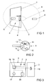
- FIG. 1 shows a door 1 of a living or office space with a closing device 2.
- the closing device 2 has a arranged on the door 1 closing unit 3 with an electronic control unit 4 and two active electronic keys 5, 5 '.
- One of the keys 5 is located close to the control unit 4 within a schematically illustrated receiving area 6 of a so-called and FIG. 3 represented RF interface 7.
- the data of the one key 5 can be read and dependent on the closing unit 3 are controlled.
- the other of the keys 5 ' is located outside the reception area 6 of the RF interface 7 of the control unit 4. Thus, the data of the other key 5 'can not be read out from the RF interface 7.
- FIG. 1 a spatial region 8 is shown, which of an in FIG. 3 illustrated radio module 9, for example, a Bluetooth interface, the control unit 4 is detected.
- This spatial area 8 is an area that is provided for monitoring by the radio module 9.
- This spatial area 8 can easily be limited via a signal strength or an antenna orientation and, in the simplest case, learned. It can be seen here that both keys 5, 5 'are located within the spatial area 8 covered by the radio module.
- FIG. 2 schematically shows a key 5 of the locking device FIG. 1 ,
- the key 5 has an energy storage 10 for supplying a key control 11 with electric current.
- the key controller 11 has a data memory, not shown.
- the key controller 11 is connected to an RF interface 12 and to the radio module 13.
- the key 5 has a push-button 14 and a signal means 15, preferably a multi-color LED for visualizing states of the closing device 2.
- FIG. 3 shows the electronic control unit 4 with the closing unit 3 from FIG. 1 , It can be seen here that the closing unit 3 has an electronic locking mechanism 16.
- the electronic control unit 4 has an energy storage 17 for supplying a control 18 with electric current.
- the controller 18 has a data memory, not shown.
- the controller 18 is connected to the in FIG. 1 said RF interface 7 and connected to the radio module 9. To increase the detected spatial area 8, the controller 18 can also be connected to further wireless modules 9, not shown.
- the controller 18 has a sensor unit 19 for detecting a located within the receiving area 6 or the spatial area 8 key 5 and for detecting the actuation of the key 14 of the key 5.
- the controller 18 is connected to a buzzer 20 which, for example, when closing the Closing unit 3 emits an acoustic signal.
- Such buzzer 20 may for example have a piezoelectric element.
- FIG. 4 shows a flowchart of a method for operating the locking device 2 FIG. 1 with the key 5 off FIG. 2 and the electronic control unit 4 with the closing unit 3 FIG. 3 ,
- the controller 18 of the control unit 4 communicates with the key controller 11 via the RF interfaces 7, 12.
- the code of the key 5 is read out and the closing unit 3 is activated and the electronic locking mechanism 16 is unlocked or locked. This corresponds to an individual release of the closing unit 3.
- the closing device 2 allows a permanent release of the closing unit 3.
- the continuous release is switched off while it is switched on in the activated state Z2.
- the closing unit 3 of the key 5 located in the ground state Z1 is presented and the button 14 is pressed, the continuous release in the state Z2 is activated in step S1.
- the release and the establishment of the connection via the radio modules 9, 13 between the keys 5 and 5 take place in the state Z3 Control unit 4.
- the locking device changes to the state Z4.
- state Z4 the connection is maintained at intervals of, for example, 2 seconds. In these intervals, it is checked whether the key 5 is still within the reception area 8. If it is determined in a step S4 that the key 5 has left the intended area, the controller 18 switches to the state Z2 and locks the closing unit 3.
- the closing unit 3 then has to be controlled again by presenting a key 5 that is authorized to close in step S2 ,
- control unit 4 can also be controlled manually by pressing the button 14 on the key 5 in step S6, so that in the state Z5, the closing unit 3 is locked, although the key 5 within the spatial area 8 of the radio module 9 of Control unit 4 is located. By pressing the button 14 again, the closing unit 3 can be controlled and unlocked again in step S5.
- the removal of the key 5 is also monitored in the state Z5, so that if the key 5 moves away from the spatial area 8 of the radio module 9 in step S7, the control unit 4 enters the state Z2 and locks the closing unit 3.
- the continuous release can then be deactivated again in step S8, when the control unit 4, the key 5 is presented and the button 14 is pressed.
- the button 14 is pressed for a certain duration of, for example, three seconds.
Landscapes
- Engineering & Computer Science (AREA)
- Computer Networks & Wireless Communication (AREA)
- Physics & Mathematics (AREA)
- General Physics & Mathematics (AREA)
- Lock And Its Accessories (AREA)
Abstract
Description
- Die Erfindung betrifft eine Schließeinrichtung eines Büro- oder Wohnraums mit einer elektronischen Schließeinheit und mit zumindest einem Schlüssel zum Schließen der Schließeinheit, mit einer drahtlosen Schnittstelle an der Schließeinheit und am Schlüssel zum Austausch von Signalen mit einem elektronischen Sperrmechanismus zur Verriegelung oder Entriegelung der Schließeinheit in Abhängigkeit von den zwischen Schlüssel und Schließeinheit übertragenen Signalen. Weiterhin betrifft die Erfindung ein Verfahren zum Betrieb einer solchen Schließeinrichtung.
- Schließeinrichtungen für Büro- oder Wohnräume, bei denen ein Code eines Schlüssels zum Schließen einer Schließeinheit ausgelesen wird, sind aus der Praxis allgemein bekannt. Bei der Schließeinheit kann es sich einen Schließzylinder oder einen elektronischen Beschlag handeln.
- Eine solche Schließeinrichtung ist beispielsweise aus der
WO 2011/109005 A1 bekannt. Bei dieser Schließeinrichtung wird erfasst, ob sich ein Schlüssel innerhalb der Reichweite eines feststehenden Sensors befindet und der Code des Schlüssels ausgelesen. Anhand der Signale des Schlüssels erfolgt eine Ansteuerung der Schließeinheit oder die Ansteuerung unterbleibt. - Bei Wohn- und Büroräumen ist es für den zum Schließen berechtigten Nutzer recht umständlich, die Schließeinheit zu verriegeln, wenn er den Raum verlässt. Bei einer Vielzahl zum Schließen berechtigten Schlüsseln kann zudem das Verriegeln der Schließeinheit vergessen werden, wenn der letzte zum Schließen berechtigte Nutzer den Raum verlässt.
- Der Erfindung liegt das Problem zugrunde, eine Schließeinrichtung der eingangs genannten Art so zu gestalten, dass sie besonders komfortabel zu bedienen ist. Weiterhin soll ein besonders komfortables Verfahren zum Betrieb einer solchen Schleißeinrichtung geschaffen werden.
- Das erstgenannte Problem wird erfindungsgemäß gelöst durch Mittel zur Erfassung eines räumlichen Bereiches, in dem sich der zumindest eine Schlüssel befindet und zur Ansteuerung des Sperrmechanismus in eine verriegelte Stellung bei Verlassen eines vorgesehenen räumlichen Bereiches des letzten Schlüssels.
- Durch diese Gestaltung weist die Schließeinheit zwei Schnittstellen auf. Über eine erste Schnittstelle wird der Schlüssel ausgelesen und über eine zweite Schnittstelle wird der räumliche Bereich erfasst, in dem sich der Schlüssel befindet oder nicht befindet. Damit ermöglicht die erfindungsgemäße Schließeinrichtung die Erzeugung zweier Betriebsmöglichkeiten, nämlich die Einzelfreigabe der Schließeinheit wie beim Stand der Technik durch Auslesen des Schlüssels und zusätzlich eine Dauerfreigabe, solange sich einer der Schlüssel in dem vorgesehenen räumlichen Bereichs befindet. Verlassen alle Nutzer mit Schlüsseln jedoch den vorgesehenen räumlichen Bereich wird die Schließeinheit angesteuert und automatisch verriegelt. Dies ist insbesondere bei Büroräumen von Vorteil, da sich die zum Schließen berechtigte Person mit dem Schlüssel aus dem Raum und damit von der Schließeinheit entfernen kann und der Raum bei aktivierter Dauerfreigabe automatisch geschlossen wird, wenn sich die Person außerhalb des vorgesehenen räumlichen Bereichs aufhält. Bei dem vorgesehenen räumlichen Bereich kann es sich um den zu schließenden Raum selbst und den Bereich unmittelbar vor dessen Tür handeln.
- Der bauliche Aufwand zur Erfassung der Entfernung des Schlüssels von der Schließeinheit lässt sich gemäß einer anderen vorteilhaften Weiterbildung der Erfindung einfach gering halten, wenn die Mittel zur Erfassung des räumlichen Bereiches, in dem sich der Schlüssel befindet ein Funkmodul mit über die Entfernung abfallender Sendeleistung aufweisen.
- Die Position und damit die Entfernung des Schlüssels von der Schließeinheit lässt sich gemäß einer anderen vorteilhaften Weiterbildung der Erfindung besonders genau bestimmen, wenn die Mittel zur Erfassung der Entfernung zumindest zwei voneinander beabstandete Funkmodule aufweisen. Diese Bestimmung der Position des Schlüssels lässt sich dank der Erfindung nach dem Verfahren der Triangulation einfach bestimmen.
- Das drahtlose Funkmodul gestaltet sich gemäß einer anderen vorteilhaften Weiterbildung der Erfindung besonders einfach, wenn das Funkmodul als Bluetooth Schnittstelle ausgebildet ist. Durch diese Gestaltung kann die Reichweiteninformation des allgemein bekannten Bluetooth Übertragungssystems genutzt werden. Die Signalstärke der Bluetooth Übertragung sinkt mit der Entfernung des Schlüssels von der Schließeinheit und lässt sich daher als Maß für die Entfernung nutzen. Weiterhin lässt sich die Bluetooth Übertragung auch zur Übertragung der zur Verriegelung oder Entriegelung des Sperrmechanismus erforderlichen Signale nutzen. Ebenso ist auch die Nutzung zweier voneinander beabstandeter Bluetooth Schnittstellen zur Bestimmung der Position des Schlüssels nach dem Verfahren der Triangulation möglich.
- Die Schließeinheit lässt sich gemäß einer anderen vorteilhaften Weiterbildung der Erfindung wahlweise für einen einzelnen Zugang ansteuern oder dauerhaft in eine entriegelte Stellung schalten, wenn der Schlüssel einen manuell zu betätigenden Taster zur Aktivierung einer Dauerfreigabe der Schließeinheit in Abhängigkeit von der erfassten Entfernung und/oder der räumlichen Position des Schlüssels. Durch diese Gestaltung ist es dem Nutzer überlassen, ob er den Taster zur Aktivierung der Dauerfreigabe betätigt. Wenn der Nutzer des mit Dauerfreigabe aktivierten Schlüssels den vorgesehenen räumlichen Bereich verlässt wird die Schließeinheit verriegelt und nach einer erneuten Rückkehr in den vorgesehenen räumlichen Bereich wieder entriegelt.
- Die Schließeinheit ermöglicht gemäß einer anderen vorteilhaften Weiterbildung der Erfindung eine besonders vielseitige Programmierung, wenn der Schlüssel und die Schließeinheit jeweils einen Speicher, ein Funkmodul und eine Schnittstelle zum Austausch von Daten aufweisen. Durch diese Gestaltung ist der zumindest eine Schlüssel ein aktives Bauteil der Schließeinheit. Berechtigungen zum Schließen können in dem Schlüssel oder in der Schließeinheit abgelegt werden. Die Schließeinheit kann dann nur geschlossen werden, wenn eine zeitliche und räumliche Berechtigung vorliegt. Selbstverständlich können sowohl im Schlüssel als auch in der Schließeinheit Ereignisse wie beispielsweise Schließvorgänge und Schließversuche abgelegt werden.
- Das zweitgenannte Problem, nämlich die Schaffung eines besonders komfortablen Verfahrens zum Betrieb einer solchen Schließeinrichtung, wird erfindungsgemäß dadurch gelöst, dass eine Einzelfreigabe der Schließeinheit durch Auslesen eines Codes des zumindest einen Schlüssels erfolgt und dass eine Dauerfreigabe der Schließeinheit erfolgt, wenn sich der zumindest eine Schlüssel innerhalb eines vorgesehenen räumlichen Bereichs befindet und dass die Schließeinheit verriegelt wird, wenn sämtliche zum Schließen berechtigte Schlüssel aus dem vorgesehenen räumlichen Bereich entfernt werden.
- Durch diese Gestaltung wird die Schließeinheit automatisch verriegelt, wenn sich kein zum Schließen berechtigter Schlüssel innerhalb des vorgesehenen räumlichen Bereichs befindet. Hierdurch kann nicht vergessen werden, den mit der Schließeinrichtung ausgestatteten Wohn- oder Büroraum beim Verlassen abzuschließen. Befindet sich jedoch ein Nutzer mit dem zum Schließen berechtigten Schlüssel innerhalb des vorgesehenen räumlichen Bereichs, meist innerhalb des zu schließenden Wohn- oder Büroraums oder unmittelbar davor, befindet sich die Schließeinheit in der entriegelten Stellung. Der Wohn- oder Büroraum kann daher ohne ständig erneut entriegelt zu werden betreten werden.
- Der Nutzer der Schließeinrichtung hat gemäß einer anderen vorteilhaften Weiterbildung der Erfindung die Wahlfreiheit, ob er eine Einzelfreigabe oder eine Dauerfreigabe der Schließeinheit wünscht, wenn die Dauerfreigabe der Schließeinheit durch manuelle Betätigung eines Tasters auf dem Schlüssel aktiviert wird.
- Die Schließeinheit lässt sich gemäß einer anderen vorteilhaften Weiterbildung der Erfindung jederzeit manuell ansteuern, wenn bei aktivierter Dauerfreigabe die Schließeinheit durch manuelle Betätigung eines Tasters angesteuert wird. Durch diese Gestaltung kann beispielsweise die Schließeinheit geschlossen werden, um den Raum zu verriegeln, wenn beispielsweise ein vertrauliches Gespräch stattfindet.
- Die Erfindung lässt zahlreiche Ausführungsformen zu. Zur weiteren Verdeutlichung ihres Grundprinzips ist eine davon in der Zeichnung dargestellt und wird nachfolgend beschrieben. Diese zeigt in
- Fig. 1
- schematisch eine Schließeinrichtung einer Wohnungs- oder Bürotür,
- Fig. 2
- schematisch einen Schlüssel der Schließeinrichtung aus
Figur 1 , - Fig. 3
- schematisch eine Schließeinheit der Schließeinrichtung aus
Figur 1 , - Fig. 4
- ein Flussdiagramm eines Verfahrens zum Betrieb der Schließeinrichtung aus
Figur 1 . -
Figur 1 zeigt eine Tür 1 eines Wohn- oder Büroraums mit einer Schließeinrichtung 2. Die Schließeinrichtung 2 hat eine an der Tür 1 angeordnete Schließeinheit 3 mit einer elektronischen Steuereinheit 4 und zwei aktiven elektronischen Schlüsseln 5, 5'. Einer der Schlüssel 5 befindet sich nahe an der Steuereinheit 4 innerhalb eines schematisch dargestellten Empfangsbereichs 6 einer sogenannten und inFigur 3 dargestellten RF-Schnittstelle 7. Die Daten des einen Schlüssels 5 können ausgelesen werden und in dessen Abhängigkeit die Schließeinheit 3 angesteuert werden. Der andere der Schlüssel 5' befindet sich außerhalb des Empfangsbereichs 6 der RF-Schnittstelle 7 der Steuereinheit 4. Damit können die Daten des anderen Schlüssels 5' nicht von der RF-Schnittstelle 7 ausgelesen werden. - Weiterhin ist in
Figur 1 ein räumlicher Bereich 8 dargestellt, welcher von einem inFigur 3 dargestellten Funkmodul 9, beispielsweise einer Bluetooth Schnittstelle, der Steuereinheit 4 erfasst wird. Bei diesem räumlichen Bereich 8 handelt es sich um einen Bereich, der zur Überwachung durch das Funkmodul 9 vorgesehen ist. Dieser räumliche Bereich 8 lässt sich über eine Signalstärke oder eine Antennenausrichtung einfach begrenzen und im einfachsten Fall einlernen. Hier ist ersichtlich, dass sich beide Schlüssel 5, 5' innerhalb des von dem Funkmodul erfassten räumlichen Bereichs 8 befinden. -
Figur 2 zeigt schematisch einen Schlüssel 5 der Schließeinrichtung ausFigur 1 . Der Schlüssel 5 hat einen Energiespeicher 10 zur Versorgung einer Schlüsselsteuerung 11 mit elektrischem Strom. Die Schlüsselsteuerung 11 weist einen nicht näher dargestellten Datenspeicher auf. Die Schlüsselsteuerung 11 ist mit einer RF-Schnittstelle 12 und mit dem Funkmodul 13 verbunden. Weiterhin hat der Schlüssel 5 einen Taster 14 und ein Signalmittel 15, vorzugsweise eine Mehrfarb-LED zur Visualisierung von Zuständen der Schließeinrichtung 2. -
Figur 3 zeigt die elektronische Steuereinheit 4 mit der Schließeinheit 3 ausFigur 1 . Hierbei ist zu erkennen, dass die Schließeinheit 3 einen elektronischen Sperrmechanismus 16 hat. Die elektronische Steuereinheit 4 hat einen Energiespeicher 17 zur Versorgung einer Steuerung 18 mit elektrischem Strom. Die Steuerung 18 weist einen nicht näher dargestellten Datenspeicher auf. - Die Steuerung 18 ist mit der in
Figur 1 genannten RF-Schnittstelle 7 und mit dem Funkmodul 9 verbunden. Die Steuerung 18 kann zur Vergrößerung des erfassten räumlichen Bereichs 8 auch mit weiteren, nicht dargestellten Funkmodulen 9 verbunden sein. Die Steuerung 18 hat eine Sensoreinheit 19 zur Erfassung eines innerhalb des Empfangsbereichs 6 oder des räumlichen Bereichs 8 befindlichen Schlüssels 5 sowie zur Erfassung der Betätigung des Tasters 14 des Schlüssels 5. Weiterhin ist die Steuerung 18 mit einem Summer 20 verbunden, welcher beispielsweise beim Schließen der Schließeinheit 3 ein akustisches Signal abgibt. Solche Summer 20 können beispielsweise ein Piezoelement aufweisen. -
Figur 4 zeigt ein Flussdiagramm eines Verfahrens zum Betrieb der Schließeinrichtung 2 ausFigur 1 mit dem Schlüssel 5 ausFigur 2 und der elektronischen Steuereinheit 4 mit der Schließeinheit 3 ausFigur 3 . Im Normalbetrieb kommuniziert die Steuerung 18 der Steuereinheit 4 mit der Schlüsselsteuerung 11 über die RF-Schnittstellen 7, 12. Dabei wird der Code des Schlüssels 5 ausgelesen und die Schließeinheit 3 angesteuert und der elektronische Sperrmechanismus 16 entriegelt oder verriegelt. Dies entspricht einer Einzelfreigabe der Schließeinheit 3. - Die Schließeinrichtung 2 ermöglicht eine Dauerfreigabe der Schließeinheit 3. Im Grundzustand Z1 ist die Dauerfreigabe ausgeschaltet, während sie im aktivierten Zustand Z2 eingeschaltet ist. Wird der im Grundzustand Z1 befindlichen Schließeinheit 3 der Schlüssel 5 präsentiert und der Taster 14 gedrückt, wird im Schritt S1 die Dauerfreigabe im Zustand Z2 aktiviert. Bei einem im Schritt S2 zum Schließen berechtigten Schlüssel 5 erfolgt im Zustand Z3 die Freigabe und der Verbindungsaufbau über die Funkmodule 9, 13 zwischen Schlüssel 5 und Steuereinheit 4. Sind im Schritt S3 die Funkmodule miteinander verbunden, wechselt die Schließeinrichtung in den Zustand Z4. Im Zustand Z4 wird die Verbindung in Intervallen von beispielsweise 2 Sekunden aufrechterhalten. In diesen Intervallen wird überprüft, ob sich der Schlüssel 5 noch innerhalb des Empfangsbereichs 8 befindet. Wird in einem Schritt S4 festgestellt, dass der Schlüssel 5 den vorgesehenen Bereich verlassen hat, schaltet die Steuerung 18 in den Zustand Z2 und sperrt die Schließeinheit 3. Die Schließeinheit 3 muss dann erneut durch Präsentation eines zum Schließen berechtigten Schlüssels 5 im Schritt S2 angesteuert werden.
- Ausgehend vom Zustand Z4 kann auch durch Drücken des Tasters 14 am Schlüssel 5 im Schritt S6 die Steuereinheit 4 auch manuell angesteuert werden, so dass im Zustand Z5 die Schließeinheit 3 verriegelt ist, obwohl sich der Schlüssel 5 innerhalb des räumlichen Bereichs 8 des Funkmoduls 9 der Steuereinheit 4 befindet. Durch erneuten Druck auf den Taster 14 kann im Schritt S5 die Schließeinheit 3 erneut angesteuert und entriegelt werden.
- Die Entfernung des Schlüssels 5 wird auch im Zustand Z5 überwacht, so dass, falls sich der Schlüssel 5 im Schritt S7 aus dem räumlichen Bereich 8 des Funkmoduls 9 entfernt, die Steuereinheit 4 in den Zustand Z2 gelangt und die Schließeinheit 3 verriegelt. Die Dauerfreigabe lässt sich anschließend im Schritt S8 wieder deaktivieren, wenn der Steuereinheit 4 der Schlüssel 5 präsentiert wird und der Taster 14 gedrückt wird. Um ein versehentliches Schalten zwischen den Zuständen Z1 und Z2 zu vermeiden, kann vorgesehen sein, dass der Taster 14 für eine bestimmte Dauer von beispielsweise drei Sekunden gedrückt wird.
Claims (9)
- Schließeinrichtung (2) eines Büro- oder Wohnraums mit einer elektronischen Schließeinheit (3) und mit zumindest einem Schlüssel (5, 5') zum Schließen der Schließeinheit (3), mit einer drahtlosen Schnittstelle (7) an der Schließeinheit (3) und am Schlüssel (5, 5') zum Austausch von Signalen mit einem elektronischen Sperrmechanismus (16) zur Verriegelung oder Entriegelung der Schließeinheit (3) in Abhängigkeit von den zwischen Schlüssel (5, 5') und Schließeinheit (3) übertragenen Signalen, gekennzeichnet durch Mittel zur Erfassung eines räumlichen Bereiches, in dem sich der zumindest eine Schlüssel (5) befindet, und zur Ansteuerung des Sperrmechanismus (16) in eine verriegelte Stellung bei Verlassen eines vorgesehenen räumlichen Bereiches des letzten Schlüssels (5).
- Schließeinrichtung nach Anspruch 1, dadurch gekennzeichnet, dass die Mittel zur Erfassung des räumlichen Bereiches, in dem sich der Schlüssel (5) befindet, ein Funkmodul (9, 13) mit über die Entfernung abfallender Sendeleistung aufweisen.
- Schließeinrichtung nach Anspruch 2, dadurch gekennzeichnet, dass die Mittel zur Erfassung der Entfernung zumindest zwei voneinander beabstandete Funkmodule (9, 13) aufweisen.
- Schließeinrichtung nach Anspruch 2 oder 3, dadurch gekennzeichnet, dass das Funkmodul (9, 13) als Bluetooth Schnittstelle ausgebildet ist.
- Schließeinrichtung nach einem der Ansprüche 1 bis 4, dadurch gekennzeichnet, dass der Schlüssel (5) einen manuell zu betätigenden Taster (14) zur Aktivierung einer Dauerfreigabe der Schließeinheit (3) in Abhängigkeit von der erfassten Entfernung und/oder der räumlichen Position des Schlüssels (5) aufweist.
- Schließeinrichtung nach einem der Ansprüche 1 bis 5, dadurch gekennzeichnet, dass der Schlüssel (5) und die Schließeinheit (3) jeweils einen Speicher, ein Funkmodul (9, 13) und eine Schnittstelle (7, 12) zum Austausch von Daten aufweisen.
- Verfahren zum Betrieb einer Schließeinrichtung (2) nach einem der vorhergehenden Ansprüche, dadurch gekennzeichnet, dass eine Einzelfreigabe der Schließeinheit (3) durch Auslesen eines Codes des zumindest einen Schlüssels (5, 5') erfolgt und dass eine Dauerfreigabe der Schließeinheit (3) erfolgt, wenn sich der zumindest eine Schlüssel (5, 5') innerhalb eines vorgesehenen räumlichen Bereichs (8) befindet und dass die Schließeinheit (3) verriegelt wird, wenn sämtliche zum Schließen berechtigte Schlüssel (5, 5') aus dem vorgesehenen räumlichen Bereich (8) entfernt werden.
- Verfahren nach Anspruch 7, dadurch gekennzeichnet, dass die Dauerfreigabe der Schließeinheit (3) durch manuelle Betätigung eines Tasters (14) auf dem Schlüssel aktiviert wird.
- Verfahren nach Anspruch 7 oder 8, dadurch gekennzeichnet, dass bei aktivierter Dauerfreigabe die Schließeinheit (3) durch manuelle Betätigung eines Tasters (14) angesteuert wird.
Priority Applications (2)
| Application Number | Priority Date | Filing Date | Title |
|---|---|---|---|
| PL14181878T PL2849159T3 (pl) | 2013-09-11 | 2014-08-22 | Układ zamykania pomieszczenia biurowego lub mieszkalnego i sposób użytkowania takiego układu zamykania |
| SI201431793T SI2849159T1 (sl) | 2013-09-11 | 2014-08-22 | Naprava za zaklepanje pisarne ali bivalnega prostora in postopek za delovanje takšne naprave za zaklepanje |
Applications Claiming Priority (1)
| Application Number | Priority Date | Filing Date | Title |
|---|---|---|---|
| DE102013218215.5A DE102013218215A1 (de) | 2013-09-11 | 2013-09-11 | Schließeinrichtung eines Büro- oder Wohnraums und Verfahren zum Betrieb einer solchen Schließeinrichtung |
Publications (2)
| Publication Number | Publication Date |
|---|---|
| EP2849159A1 true EP2849159A1 (de) | 2015-03-18 |
| EP2849159B1 EP2849159B1 (de) | 2021-02-24 |
Family
ID=51518523
Family Applications (1)
| Application Number | Title | Priority Date | Filing Date |
|---|---|---|---|
| EP14181878.1A Active EP2849159B1 (de) | 2013-09-11 | 2014-08-22 | Schließeinrichtung eines Büro- oder Wohnraums und Verfahren zum Betrieb einer solchen Schließeinrichtung |
Country Status (5)
| Country | Link |
|---|---|
| EP (1) | EP2849159B1 (de) |
| DE (1) | DE102013218215A1 (de) |
| ES (1) | ES2859600T3 (de) |
| PL (1) | PL2849159T3 (de) |
| SI (1) | SI2849159T1 (de) |
Citations (3)
| Publication number | Priority date | Publication date | Assignee | Title |
|---|---|---|---|---|
| EP1039075A2 (de) * | 1999-03-19 | 2000-09-27 | DaimlerChrysler AG | Elektronische Schliessanlage, insbesondere Fahrzeugschliessanlage |
| US20030029579A1 (en) * | 2001-07-10 | 2003-02-13 | Overhead Door Corporation | Automatic barrier operator system |
| WO2011109005A1 (en) | 2010-03-02 | 2011-09-09 | Utc Fire & Security Corporation | Seamless authentication system |
-
2013
- 2013-09-11 DE DE102013218215.5A patent/DE102013218215A1/de not_active Withdrawn
-
2014
- 2014-08-22 ES ES14181878T patent/ES2859600T3/es active Active
- 2014-08-22 EP EP14181878.1A patent/EP2849159B1/de active Active
- 2014-08-22 SI SI201431793T patent/SI2849159T1/sl unknown
- 2014-08-22 PL PL14181878T patent/PL2849159T3/pl unknown
Patent Citations (3)
| Publication number | Priority date | Publication date | Assignee | Title |
|---|---|---|---|---|
| EP1039075A2 (de) * | 1999-03-19 | 2000-09-27 | DaimlerChrysler AG | Elektronische Schliessanlage, insbesondere Fahrzeugschliessanlage |
| US20030029579A1 (en) * | 2001-07-10 | 2003-02-13 | Overhead Door Corporation | Automatic barrier operator system |
| WO2011109005A1 (en) | 2010-03-02 | 2011-09-09 | Utc Fire & Security Corporation | Seamless authentication system |
Also Published As
| Publication number | Publication date |
|---|---|
| SI2849159T1 (sl) | 2021-04-30 |
| ES2859600T3 (es) | 2021-10-04 |
| PL2849159T3 (pl) | 2021-07-12 |
| EP2849159B1 (de) | 2021-02-24 |
| DE102013218215A1 (de) | 2015-03-12 |
Similar Documents
| Publication | Publication Date | Title |
|---|---|---|
| EP3077997B1 (de) | Verfahren zum bewirken einer änderung eines betriebsmodus | |
| EP3542350B1 (de) | Zugangskontrollsystem mit automatischer statusaktualisierung | |
| DE4402853C1 (de) | Handsender zur Fernbedienung verschiedener Fahrzeugsysteme | |
| DE112016004525T5 (de) | Elektronische Tastatursperre und elektronische Verriegelungssystem für Möbel, Schränke oder Schliessfächer | |
| DE102006053964A1 (de) | Fahrzeugausstattungssteuersystem | |
| DE102009016185A1 (de) | Passives Entriegelungssystem und -verfahren | |
| DE102012221016A1 (de) | Schließeinheit, Schließvorrichtung und Verfahren zum Entriegeln und/oder Verriegeln eines Schlosses | |
| DE102007035069A1 (de) | Verfahren und Vorrichtung zum Nutzen eines Senders mit einer Bereichsbegrenzung, um eine bewegliche Barrierenbedienvorrichtung zu steuern | |
| EP3479362B1 (de) | Schliessanordnung für einen schaltschrank und ein entsprechendes verfahren | |
| DE102016106799A1 (de) | Bewegungsbasiertes kapazitives Sensorsystem | |
| DE102007060810A1 (de) | Anordnung, System und Verfahren zur drahtlosen Steuerung eines Gerätes | |
| EP2551427A2 (de) | Schlossvorrichtung für Gepäck- und/oder Möbelstücke | |
| DE10114214A1 (de) | Kontrollvorrichtung zur Zugangs-oder Bediennungsberechtigung für Türen oder Fenster | |
| DE102018131371A1 (de) | Identifikationsgeber | |
| EP3362997B1 (de) | Abschliessbares behältnis | |
| EP3096297A1 (de) | Schliessanlage für eine gebäudetür | |
| EP2849159B1 (de) | Schließeinrichtung eines Büro- oder Wohnraums und Verfahren zum Betrieb einer solchen Schließeinrichtung | |
| EP3027827B1 (de) | Elektromagnetisch sperrbarer fenstergriff | |
| DE202015008986U1 (de) | Fenster- oder Türgriff mit einer Vorrichtung zur Erfassung der Griffposition | |
| EP3481680B1 (de) | Verfahren zum betreiben eines passiven zugangssystems für ein kraftfahrzeug mit einem id-geber | |
| AT10186U1 (de) | Authentifizierungsvorrichtung und -system | |
| EP4303839A1 (de) | Elektronische schliesszustandsüberwachung eines utility-schliesssystems | |
| EP3382317B1 (de) | Freigabesteuervorrichtung und verfahren | |
| EP2955701A2 (de) | Funkgesteuertes elektromechanisches Schließsystem und Verfahren zum Betrieb eines funkgesteuerten elektromechanischen Schließsystems | |
| EP2998462B1 (de) | Fluchtwegsicherungseinrichtung |
Legal Events
| Date | Code | Title | Description |
|---|---|---|---|
| PUAI | Public reference made under article 153(3) epc to a published international application that has entered the european phase |
Free format text: ORIGINAL CODE: 0009012 |
|
| 17P | Request for examination filed |
Effective date: 20140822 |
|
| AK | Designated contracting states |
Kind code of ref document: A1 Designated state(s): AL AT BE BG CH CY CZ DE DK EE ES FI FR GB GR HR HU IE IS IT LI LT LU LV MC MK MT NL NO PL PT RO RS SE SI SK SM TR |
|
| AX | Request for extension of the european patent |
Extension state: BA ME |
|
| R17P | Request for examination filed (corrected) |
Effective date: 20150730 |
|
| RBV | Designated contracting states (corrected) |
Designated state(s): AL AT BE BG CH CY CZ DE DK EE ES FI FR GB GR HR HU IE IS IT LI LT LU LV MC MK MT NL NO PL PT RO RS SE SI SK SM TR |
|
| 17Q | First examination report despatched |
Effective date: 20160224 |
|
| STAA | Information on the status of an ep patent application or granted ep patent |
Free format text: STATUS: EXAMINATION IS IN PROGRESS |
|
| GRAP | Despatch of communication of intention to grant a patent |
Free format text: ORIGINAL CODE: EPIDOSNIGR1 |
|
| STAA | Information on the status of an ep patent application or granted ep patent |
Free format text: STATUS: GRANT OF PATENT IS INTENDED |
|
| INTG | Intention to grant announced |
Effective date: 20201002 |
|
| GRAS | Grant fee paid |
Free format text: ORIGINAL CODE: EPIDOSNIGR3 |
|
| GRAA | (expected) grant |
Free format text: ORIGINAL CODE: 0009210 |
|
| STAA | Information on the status of an ep patent application or granted ep patent |
Free format text: STATUS: THE PATENT HAS BEEN GRANTED |
|
| AK | Designated contracting states |
Kind code of ref document: B1 Designated state(s): AL AT BE BG CH CY CZ DE DK EE ES FI FR GB GR HR HU IE IS IT LI LT LU LV MC MK MT NL NO PL PT RO RS SE SI SK SM TR |
|
| REG | Reference to a national code |
Ref country code: GB Ref legal event code: FG4D Free format text: NOT ENGLISH |
|
| REG | Reference to a national code |
Ref country code: CH Ref legal event code: EP |
|
| REG | Reference to a national code |
Ref country code: DE Ref legal event code: R096 Ref document number: 502014015288 Country of ref document: DE |
|
| REG | Reference to a national code |
Ref country code: AT Ref legal event code: REF Ref document number: 1365458 Country of ref document: AT Kind code of ref document: T Effective date: 20210315 Ref country code: CH Ref legal event code: NV Representative=s name: VALIPAT S.A. C/O BOVARD SA NEUCHATEL, CH |
|
| REG | Reference to a national code |
Ref country code: IE Ref legal event code: FG4D Free format text: LANGUAGE OF EP DOCUMENT: GERMAN |
|
| REG | Reference to a national code |
Ref country code: RO Ref legal event code: EPE |
|
| REG | Reference to a national code |
Ref country code: NL Ref legal event code: FP |
|
| REG | Reference to a national code |
Ref country code: GR Ref legal event code: EP Ref document number: 20210400791 Country of ref document: GR Effective date: 20210519 |
|
| REG | Reference to a national code |
Ref country code: LT Ref legal event code: MG9D |
|
| PG25 | Lapsed in a contracting state [announced via postgrant information from national office to epo] |
Ref country code: HR Free format text: LAPSE BECAUSE OF FAILURE TO SUBMIT A TRANSLATION OF THE DESCRIPTION OR TO PAY THE FEE WITHIN THE PRESCRIBED TIME-LIMIT Effective date: 20210224 Ref country code: FI Free format text: LAPSE BECAUSE OF FAILURE TO SUBMIT A TRANSLATION OF THE DESCRIPTION OR TO PAY THE FEE WITHIN THE PRESCRIBED TIME-LIMIT Effective date: 20210224 Ref country code: PT Free format text: LAPSE BECAUSE OF FAILURE TO SUBMIT A TRANSLATION OF THE DESCRIPTION OR TO PAY THE FEE WITHIN THE PRESCRIBED TIME-LIMIT Effective date: 20210624 Ref country code: LT Free format text: LAPSE BECAUSE OF FAILURE TO SUBMIT A TRANSLATION OF THE DESCRIPTION OR TO PAY THE FEE WITHIN THE PRESCRIBED TIME-LIMIT Effective date: 20210224 Ref country code: BG Free format text: LAPSE BECAUSE OF FAILURE TO SUBMIT A TRANSLATION OF THE DESCRIPTION OR TO PAY THE FEE WITHIN THE PRESCRIBED TIME-LIMIT Effective date: 20210524 Ref country code: NO Free format text: LAPSE BECAUSE OF FAILURE TO SUBMIT A TRANSLATION OF THE DESCRIPTION OR TO PAY THE FEE WITHIN THE PRESCRIBED TIME-LIMIT Effective date: 20210524 |
|
| PG25 | Lapsed in a contracting state [announced via postgrant information from national office to epo] |
Ref country code: SE Free format text: LAPSE BECAUSE OF FAILURE TO SUBMIT A TRANSLATION OF THE DESCRIPTION OR TO PAY THE FEE WITHIN THE PRESCRIBED TIME-LIMIT Effective date: 20210224 Ref country code: RS Free format text: LAPSE BECAUSE OF FAILURE TO SUBMIT A TRANSLATION OF THE DESCRIPTION OR TO PAY THE FEE WITHIN THE PRESCRIBED TIME-LIMIT Effective date: 20210224 Ref country code: LV Free format text: LAPSE BECAUSE OF FAILURE TO SUBMIT A TRANSLATION OF THE DESCRIPTION OR TO PAY THE FEE WITHIN THE PRESCRIBED TIME-LIMIT Effective date: 20210224 |
|
| PG25 | Lapsed in a contracting state [announced via postgrant information from national office to epo] |
Ref country code: IS Free format text: LAPSE BECAUSE OF FAILURE TO SUBMIT A TRANSLATION OF THE DESCRIPTION OR TO PAY THE FEE WITHIN THE PRESCRIBED TIME-LIMIT Effective date: 20210624 |
|
| REG | Reference to a national code |
Ref country code: ES Ref legal event code: FG2A Ref document number: 2859600 Country of ref document: ES Kind code of ref document: T3 Effective date: 20211004 |
|
| PG25 | Lapsed in a contracting state [announced via postgrant information from national office to epo] |
Ref country code: SM Free format text: LAPSE BECAUSE OF FAILURE TO SUBMIT A TRANSLATION OF THE DESCRIPTION OR TO PAY THE FEE WITHIN THE PRESCRIBED TIME-LIMIT Effective date: 20210224 Ref country code: EE Free format text: LAPSE BECAUSE OF FAILURE TO SUBMIT A TRANSLATION OF THE DESCRIPTION OR TO PAY THE FEE WITHIN THE PRESCRIBED TIME-LIMIT Effective date: 20210224 |
|
| REG | Reference to a national code |
Ref country code: DE Ref legal event code: R097 Ref document number: 502014015288 Country of ref document: DE |
|
| PG25 | Lapsed in a contracting state [announced via postgrant information from national office to epo] |
Ref country code: SK Free format text: LAPSE BECAUSE OF FAILURE TO SUBMIT A TRANSLATION OF THE DESCRIPTION OR TO PAY THE FEE WITHIN THE PRESCRIBED TIME-LIMIT Effective date: 20210224 Ref country code: DK Free format text: LAPSE BECAUSE OF FAILURE TO SUBMIT A TRANSLATION OF THE DESCRIPTION OR TO PAY THE FEE WITHIN THE PRESCRIBED TIME-LIMIT Effective date: 20210224 |
|
| PLBE | No opposition filed within time limit |
Free format text: ORIGINAL CODE: 0009261 |
|
| STAA | Information on the status of an ep patent application or granted ep patent |
Free format text: STATUS: NO OPPOSITION FILED WITHIN TIME LIMIT |
|
| PG25 | Lapsed in a contracting state [announced via postgrant information from national office to epo] |
Ref country code: AL Free format text: LAPSE BECAUSE OF FAILURE TO SUBMIT A TRANSLATION OF THE DESCRIPTION OR TO PAY THE FEE WITHIN THE PRESCRIBED TIME-LIMIT Effective date: 20210224 |
|
| 26N | No opposition filed |
Effective date: 20211125 |
|
| PG25 | Lapsed in a contracting state [announced via postgrant information from national office to epo] |
Ref country code: MC Free format text: LAPSE BECAUSE OF FAILURE TO SUBMIT A TRANSLATION OF THE DESCRIPTION OR TO PAY THE FEE WITHIN THE PRESCRIBED TIME-LIMIT Effective date: 20210224 |
|
| PG25 | Lapsed in a contracting state [announced via postgrant information from national office to epo] |
Ref country code: IS Free format text: LAPSE BECAUSE OF FAILURE TO SUBMIT A TRANSLATION OF THE DESCRIPTION OR TO PAY THE FEE WITHIN THE PRESCRIBED TIME-LIMIT Effective date: 20210624 Ref country code: LU Free format text: LAPSE BECAUSE OF NON-PAYMENT OF DUE FEES Effective date: 20210822 |
|
| PG25 | Lapsed in a contracting state [announced via postgrant information from national office to epo] |
Ref country code: IE Free format text: LAPSE BECAUSE OF NON-PAYMENT OF DUE FEES Effective date: 20210822 |
|
| PG25 | Lapsed in a contracting state [announced via postgrant information from national office to epo] |
Ref country code: HU Free format text: LAPSE BECAUSE OF FAILURE TO SUBMIT A TRANSLATION OF THE DESCRIPTION OR TO PAY THE FEE WITHIN THE PRESCRIBED TIME-LIMIT; INVALID AB INITIO Effective date: 20140822 |
|
| P01 | Opt-out of the competence of the unified patent court (upc) registered |
Effective date: 20230515 |
|
| PG25 | Lapsed in a contracting state [announced via postgrant information from national office to epo] |
Ref country code: CY Free format text: LAPSE BECAUSE OF FAILURE TO SUBMIT A TRANSLATION OF THE DESCRIPTION OR TO PAY THE FEE WITHIN THE PRESCRIBED TIME-LIMIT Effective date: 20210224 |
|
| PG25 | Lapsed in a contracting state [announced via postgrant information from national office to epo] |
Ref country code: MK Free format text: LAPSE BECAUSE OF FAILURE TO SUBMIT A TRANSLATION OF THE DESCRIPTION OR TO PAY THE FEE WITHIN THE PRESCRIBED TIME-LIMIT Effective date: 20210224 |
|
| PG25 | Lapsed in a contracting state [announced via postgrant information from national office to epo] |
Ref country code: MT Free format text: LAPSE BECAUSE OF FAILURE TO SUBMIT A TRANSLATION OF THE DESCRIPTION OR TO PAY THE FEE WITHIN THE PRESCRIBED TIME-LIMIT Effective date: 20210224 |
|
| PGFP | Annual fee paid to national office [announced via postgrant information from national office to epo] |
Ref country code: GR Payment date: 20240819 Year of fee payment: 11 |
|
| PGFP | Annual fee paid to national office [announced via postgrant information from national office to epo] |
Ref country code: CH Payment date: 20240901 Year of fee payment: 11 |
|
| PGFP | Annual fee paid to national office [announced via postgrant information from national office to epo] |
Ref country code: CZ Payment date: 20240809 Year of fee payment: 11 |
|
| PGFP | Annual fee paid to national office [announced via postgrant information from national office to epo] |
Ref country code: PL Payment date: 20240813 Year of fee payment: 11 |
|
| PGFP | Annual fee paid to national office [announced via postgrant information from national office to epo] |
Ref country code: SI Payment date: 20240812 Year of fee payment: 11 |
|
| PGFP | Annual fee paid to national office [announced via postgrant information from national office to epo] |
Ref country code: RO Payment date: 20240820 Year of fee payment: 11 |
|
| REG | Reference to a national code |
Ref country code: DE Ref legal event code: R081 Ref document number: 502014015288 Country of ref document: DE Owner name: AUG. WINKHAUS SE & CO. KG, DE Free format text: FORMER OWNER: AUG. WINKHAUS GMBH & CO. KG, 48291 TELGTE, DE Ref country code: DE Ref legal event code: R081 Ref document number: 502014015288 Country of ref document: DE Owner name: AUG. WINKHAUS SE, DE Free format text: FORMER OWNER: AUG. WINKHAUS GMBH & CO. KG, 48291 TELGTE, DE |
|
| REG | Reference to a national code |
Ref country code: DE Ref legal event code: R081 Ref document number: 502014015288 Country of ref document: DE Owner name: AUG. WINKHAUS SE, DE Free format text: FORMER OWNER: AUG. WINKHAUS SE & CO. KG, 48291 TELGTE, DE |
|
| PGFP | Annual fee paid to national office [announced via postgrant information from national office to epo] |
Ref country code: NL Payment date: 20250821 Year of fee payment: 12 |
|
| PGFP | Annual fee paid to national office [announced via postgrant information from national office to epo] |
Ref country code: ES Payment date: 20250917 Year of fee payment: 12 |
|
| PGFP | Annual fee paid to national office [announced via postgrant information from national office to epo] |
Ref country code: DE Payment date: 20250819 Year of fee payment: 12 |
|
| PGFP | Annual fee paid to national office [announced via postgrant information from national office to epo] |
Ref country code: IT Payment date: 20250829 Year of fee payment: 12 |
|
| PGFP | Annual fee paid to national office [announced via postgrant information from national office to epo] |
Ref country code: BE Payment date: 20250820 Year of fee payment: 12 Ref country code: GB Payment date: 20250822 Year of fee payment: 12 |
|
| PGFP | Annual fee paid to national office [announced via postgrant information from national office to epo] |
Ref country code: AT Payment date: 20250819 Year of fee payment: 12 Ref country code: FR Payment date: 20250821 Year of fee payment: 12 |
|
| PG25 | Lapsed in a contracting state [announced via postgrant information from national office to epo] |
Ref country code: TR Free format text: LAPSE BECAUSE OF FAILURE TO SUBMIT A TRANSLATION OF THE DESCRIPTION OR TO PAY THE FEE WITHIN THE PRESCRIBED TIME-LIMIT Effective date: 20210224 |
|
| REG | Reference to a national code |
Ref country code: CH Ref legal event code: H13 Free format text: ST27 STATUS EVENT CODE: U-0-0-H10-H13 (AS PROVIDED BY THE NATIONAL OFFICE) Effective date: 20260324 |
|
| PG25 | Lapsed in a contracting state [announced via postgrant information from national office to epo] |
Ref country code: RO Free format text: LAPSE BECAUSE OF NON-PAYMENT OF DUE FEES Effective date: 20250822 |
|
| PG25 | Lapsed in a contracting state [announced via postgrant information from national office to epo] |
Ref country code: CH Free format text: LAPSE BECAUSE OF NON-PAYMENT OF DUE FEES Effective date: 20250831 Ref country code: CZ Free format text: LAPSE BECAUSE OF NON-PAYMENT OF DUE FEES Effective date: 20250822 |
|
| PG25 | Lapsed in a contracting state [announced via postgrant information from national office to epo] |
Ref country code: GR Free format text: LAPSE BECAUSE OF NON-PAYMENT OF DUE FEES Effective date: 20260309 |