EP2848358B1 - Palette zum Transport von zu bearbeitenden Werkstücken - Google Patents
Palette zum Transport von zu bearbeitenden Werkstücken Download PDFInfo
- Publication number
- EP2848358B1 EP2848358B1 EP14184595.8A EP14184595A EP2848358B1 EP 2848358 B1 EP2848358 B1 EP 2848358B1 EP 14184595 A EP14184595 A EP 14184595A EP 2848358 B1 EP2848358 B1 EP 2848358B1
- Authority
- EP
- European Patent Office
- Prior art keywords
- pallet
- base frame
- assembly
- pallet according
- substructure
- Prior art date
- Legal status (The legal status is an assumption and is not a legal conclusion. Google has not performed a legal analysis and makes no representation as to the accuracy of the status listed.)
- Active
Links
Images


Classifications
-
- B—PERFORMING OPERATIONS; TRANSPORTING
- B23—MACHINE TOOLS; METAL-WORKING NOT OTHERWISE PROVIDED FOR
- B23Q—DETAILS, COMPONENTS, OR ACCESSORIES FOR MACHINE TOOLS, e.g. ARRANGEMENTS FOR COPYING OR CONTROLLING; MACHINE TOOLS IN GENERAL CHARACTERISED BY THE CONSTRUCTION OF PARTICULAR DETAILS OR COMPONENTS; COMBINATIONS OR ASSOCIATIONS OF METAL-WORKING MACHINES, NOT DIRECTED TO A PARTICULAR RESULT
- B23Q1/00—Members which are comprised in the general build-up of a form of machine, particularly relatively large fixed members
- B23Q1/25—Movable or adjustable work or tool supports
- B23Q1/44—Movable or adjustable work or tool supports using particular mechanisms
- B23Q1/48—Movable or adjustable work or tool supports using particular mechanisms with sliding pairs and rotating pairs
- B23Q1/4852—Movable or adjustable work or tool supports using particular mechanisms with sliding pairs and rotating pairs a single sliding pair followed perpendicularly by a single rotating pair
-
- B—PERFORMING OPERATIONS; TRANSPORTING
- B23—MACHINE TOOLS; METAL-WORKING NOT OTHERWISE PROVIDED FOR
- B23Q—DETAILS, COMPONENTS, OR ACCESSORIES FOR MACHINE TOOLS, e.g. ARRANGEMENTS FOR COPYING OR CONTROLLING; MACHINE TOOLS IN GENERAL CHARACTERISED BY THE CONSTRUCTION OF PARTICULAR DETAILS OR COMPONENTS; COMBINATIONS OR ASSOCIATIONS OF METAL-WORKING MACHINES, NOT DIRECTED TO A PARTICULAR RESULT
- B23Q1/00—Members which are comprised in the general build-up of a form of machine, particularly relatively large fixed members
- B23Q1/25—Movable or adjustable work or tool supports
- B23Q1/44—Movable or adjustable work or tool supports using particular mechanisms
- B23Q1/50—Movable or adjustable work or tool supports using particular mechanisms with rotating pairs only, the rotating pairs being the first two elements of the mechanism
- B23Q1/52—Movable or adjustable work or tool supports using particular mechanisms with rotating pairs only, the rotating pairs being the first two elements of the mechanism a single rotating pair
- B23Q1/522—Movable or adjustable work or tool supports using particular mechanisms with rotating pairs only, the rotating pairs being the first two elements of the mechanism a single rotating pair which is perpendicular to the working surface
-
- B—PERFORMING OPERATIONS; TRANSPORTING
- B23—MACHINE TOOLS; METAL-WORKING NOT OTHERWISE PROVIDED FOR
- B23Q—DETAILS, COMPONENTS, OR ACCESSORIES FOR MACHINE TOOLS, e.g. ARRANGEMENTS FOR COPYING OR CONTROLLING; MACHINE TOOLS IN GENERAL CHARACTERISED BY THE CONSTRUCTION OF PARTICULAR DETAILS OR COMPONENTS; COMBINATIONS OR ASSOCIATIONS OF METAL-WORKING MACHINES, NOT DIRECTED TO A PARTICULAR RESULT
- B23Q1/00—Members which are comprised in the general build-up of a form of machine, particularly relatively large fixed members
- B23Q1/25—Movable or adjustable work or tool supports
- B23Q1/64—Movable or adjustable work or tool supports characterised by the purpose of the movement
- B23Q1/66—Worktables interchangeably movable into operating positions
-
- B—PERFORMING OPERATIONS; TRANSPORTING
- B23—MACHINE TOOLS; METAL-WORKING NOT OTHERWISE PROVIDED FOR
- B23Q—DETAILS, COMPONENTS, OR ACCESSORIES FOR MACHINE TOOLS, e.g. ARRANGEMENTS FOR COPYING OR CONTROLLING; MACHINE TOOLS IN GENERAL CHARACTERISED BY THE CONSTRUCTION OF PARTICULAR DETAILS OR COMPONENTS; COMBINATIONS OR ASSOCIATIONS OF METAL-WORKING MACHINES, NOT DIRECTED TO A PARTICULAR RESULT
- B23Q16/00—Equipment for precise positioning of tool or work into particular locations not otherwise provided for
- B23Q16/008—Cushioning the abutting movement
-
- B—PERFORMING OPERATIONS; TRANSPORTING
- B23—MACHINE TOOLS; METAL-WORKING NOT OTHERWISE PROVIDED FOR
- B23Q—DETAILS, COMPONENTS, OR ACCESSORIES FOR MACHINE TOOLS, e.g. ARRANGEMENTS FOR COPYING OR CONTROLLING; MACHINE TOOLS IN GENERAL CHARACTERISED BY THE CONSTRUCTION OF PARTICULAR DETAILS OR COMPONENTS; COMBINATIONS OR ASSOCIATIONS OF METAL-WORKING MACHINES, NOT DIRECTED TO A PARTICULAR RESULT
- B23Q3/00—Devices holding, supporting, or positioning work or tools, of a kind normally removable from the machine
- B23Q3/02—Devices holding, supporting, or positioning work or tools, of a kind normally removable from the machine for mounting on a work-table, tool-slide, or analogous part
- B23Q3/06—Work-clamping means
-
- B—PERFORMING OPERATIONS; TRANSPORTING
- B23—MACHINE TOOLS; METAL-WORKING NOT OTHERWISE PROVIDED FOR
- B23Q—DETAILS, COMPONENTS, OR ACCESSORIES FOR MACHINE TOOLS, e.g. ARRANGEMENTS FOR COPYING OR CONTROLLING; MACHINE TOOLS IN GENERAL CHARACTERISED BY THE CONSTRUCTION OF PARTICULAR DETAILS OR COMPONENTS; COMBINATIONS OR ASSOCIATIONS OF METAL-WORKING MACHINES, NOT DIRECTED TO A PARTICULAR RESULT
- B23Q3/00—Devices holding, supporting, or positioning work or tools, of a kind normally removable from the machine
- B23Q3/02—Devices holding, supporting, or positioning work or tools, of a kind normally removable from the machine for mounting on a work-table, tool-slide, or analogous part
- B23Q3/10—Auxiliary devices, e.g. bolsters, extension members
- B23Q3/103—Constructional elements used for constructing work holders
-
- B—PERFORMING OPERATIONS; TRANSPORTING
- B23—MACHINE TOOLS; METAL-WORKING NOT OTHERWISE PROVIDED FOR
- B23Q—DETAILS, COMPONENTS, OR ACCESSORIES FOR MACHINE TOOLS, e.g. ARRANGEMENTS FOR COPYING OR CONTROLLING; MACHINE TOOLS IN GENERAL CHARACTERISED BY THE CONSTRUCTION OF PARTICULAR DETAILS OR COMPONENTS; COMBINATIONS OR ASSOCIATIONS OF METAL-WORKING MACHINES, NOT DIRECTED TO A PARTICULAR RESULT
- B23Q7/00—Arrangements for handling work specially combined with or arranged in, or specially adapted for use in connection with, machine tools, e.g. for conveying, loading, positioning, discharging, sorting
- B23Q7/02—Arrangements for handling work specially combined with or arranged in, or specially adapted for use in connection with, machine tools, e.g. for conveying, loading, positioning, discharging, sorting by means of drums or rotating tables or discs
-
- B—PERFORMING OPERATIONS; TRANSPORTING
- B23—MACHINE TOOLS; METAL-WORKING NOT OTHERWISE PROVIDED FOR
- B23Q—DETAILS, COMPONENTS, OR ACCESSORIES FOR MACHINE TOOLS, e.g. ARRANGEMENTS FOR COPYING OR CONTROLLING; MACHINE TOOLS IN GENERAL CHARACTERISED BY THE CONSTRUCTION OF PARTICULAR DETAILS OR COMPONENTS; COMBINATIONS OR ASSOCIATIONS OF METAL-WORKING MACHINES, NOT DIRECTED TO A PARTICULAR RESULT
- B23Q7/00—Arrangements for handling work specially combined with or arranged in, or specially adapted for use in connection with, machine tools, e.g. for conveying, loading, positioning, discharging, sorting
- B23Q7/14—Arrangements for handling work specially combined with or arranged in, or specially adapted for use in connection with, machine tools, e.g. for conveying, loading, positioning, discharging, sorting co-ordinated in production lines
- B23Q7/1426—Arrangements for handling work specially combined with or arranged in, or specially adapted for use in connection with, machine tools, e.g. for conveying, loading, positioning, discharging, sorting co-ordinated in production lines with work holders not rigidly fixed to the transport devices
Definitions
- the invention relates to a pallet according to the preamble of claim 1.
- a device of the type mentioned is, for example, from the EP 1 391 262 A1 known.
- pallets are used, which serve to transport the workpiece to and from one or more workstation (s) in which a processing of the workpiece takes place.
- the workpiece is fixedly mounted in the known pallets and in its position relative to the pallet not good or not changeable. This leads, especially in the production of workpieces with a complex shape to strong restrictions - especially with regard to a full automation of the required processing steps. It is therefore an object of the invention to overcome the above-mentioned disadvantages of the prior art.
- the substructure and the structure each have a toothing in the region of a connection point, which teeth engage one another in a position of the structure fixed relative to the substructure. Due to the toothing can parallel to a dividing plane of the substructure and construction of the pallet a positive connection are created, which can be a very good security against unwanted twisting of the structure relative to the substructure prevent.
- the gearing also gives a better accuracy in the positioning of the body.
- a frictional connection although the position of the structure relative to the base can be adjusted continuously, but for a possibly used for twisting actuator must be controlled very accurately.
- a tolerance of approximately half the pitch of the toothing can be accepted. This is therefore correspondingly inexpensive to produce, with the required accuracy depending on the pallet and can be adjusted during assembly.
- a twisting of the structure relative to the substructure is facilitated by the fact that the toothings are each arranged along at least one section of a circular line or arc line.
- the substructure can have guide elements, in particular guide jaws or guide rails, for rails on an end region facing away from the structure.
- At least one of the guide elements can have at least one groove extending in the longitudinal direction of the guide element.
- the cover may be formed higher at one end than at the other end so that the higher end of the cover of a first pallet may engage over the lower end of an adjacent pallet to ensure a good seal. Furthermore, the covers can each have at least one labyrinth seal at their cooperating ends.
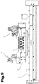
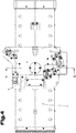
- FIGS. 1 to 4 has a pallet 1 according to the invention for the transport of workpieces to be machined, a substructure 2 and a structure 3.
- a clamping device 4 On the structure of a clamping device 4 is arranged with a plurality of clamping means. About media connections 5, the clamping device can be operated in a conventional manner. So can the clamping device 4 are closed hydraulically or pneumatically after clamping the workpiece in a conventional manner via the media connections.
- the structure 3 can be rotated together with the clamping device 4 for setting a predeterminable position relative to the base 2 about a rotation axis a.
- the axis of rotation a is preferably normal to a dividing plane of substructure 2 and philosophical.3. After setting the desired position of the structure 3 can be fixed against rotation against unintentional rotation about the axis of rotation a relative to the base 2.
- the structure 3 may, for example, be non-positively and / or frictionally connected to the substructure 2.
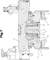
- the base 2 and the structure 3 in the region of a connection point each have a toothing 6, 7, which are in a fixed relative to the base 2 position of the structure 3 with each other.
- the teeth 6 and 7 can be a rotation of the structure 2 according to a defined by the distance of the teeth of the respective toothing 6, 7 perform increment.
- the toothings 6 and 7 are preferably congruent and concentric with one another and are arranged along a circular line or a section of the same or a curved line.
- the structure 3 may be connected to a piston-shaped member 9.
- the component 9 engages in a receptacle 8 of the substructure 2.
- the piston-shaped component 9 is arranged captive in the substructure 2 and has at least in its region which is arranged in the receptacle 8, a T-shaped cross section.
- the piston-shaped component 9 can be mounted parallel to the axis of rotation a displaceable in the substructure 2.
- the structure 2 in turn can be rotatably mounted on the piston-shaped component 9 about the axis of rotation a, wherein the structure 2 in the direction of the axis of rotation of the component 9 can not be solved, but this a certain displaceability of the structure 2 relative to the component 9 along the axis of rotation a does not exclude.
- a pressure-generating means 10 is arranged in the receptacle 8 of the base 2.
- a coil spring for example, with a rectangular cross-section, for use, but instead of a coil spring, other springs, such as (rubber) laminated springs, pneumatic, hydraulic, hydropneumatic or (electro) mechanical actuators for pressure generation can be used.
- the helical spring is arranged concentrically with a shank of the component 9 and is supported at one end on a projection 11 of the component 9 on the one hand and on a cover of the spring opposite the at least one projection 11 in the direction of the structure 3 on the other hand.
- the cover of the spring is in Fig. 6 provided with the reference numeral 12 and also closes the receptacle 8, wherein the cover 12 may be connected to the base 2, for example by means of bolts or screws.
- the helical spring with its projection 11 opposite, free end can also be supported on an inner projection or a wall of the receptacle 8.
- the piston-shaped member 9 can be acted upon by a force acting in the direction of the structure 3 force. This can be done for example in a processing station of the system in which the pallet 1 is used by an actuator acting on the projection 11, which presses the component 9 in the direction of the structure 3 and so connected to the component 9 Structure 3 of the substructure 3 separates or the teeth 6 and 7 disengages.
- the actuator used to lift the component 9 may be, for example, a hydropneumatic, hydraulic, pneumatic, mechanical or electromechanical actuator.
- the structure can be realigned according to the requirements, ie rotated in accordance with the axis of rotation a accordingly.
- the teeth 6 and 7 can interengage again and the substructure is by the force of the pressure-generating Held back in position by 10.
- the pressure-generating means 10 could also be arranged between the projection 11 and a bottom of the receptacle 8 traction means in the form of a suitable actuator to generate the necessary force to fix the structure 3 relative to the substructure 2.
- at least one of the guide elements 13, 14 may have a running L-shaped groove 15.
- the base 2 may each have at least one outwardly projecting buffer 16 at its front ends, which cooperates with buffers of the immediately adjacent pallets 1 in a processing plant.
- cover plates 17 may be provided, which cover the respective associated buffer 16 and extend over the width of the respective end face.
- the cover plates 17 may in this case be designed so that overlap the cover plates of two adjacent pallets 1 in a processing plant such as roof tiles to form a well sealed surface and to avoid contamination of the rails.
- the overlapping cover plates 17 of two pallets 1 can form a labyrinth seal.
- An advance of the pallets 1 along rails in a processing plant can be effected by a slide, for example a pneumatically, hydraulically, hydro-pneumatically, mechanically or electromechanically operated push rod.
- a slide closest to the pallet 1 a series of close-fitting pallets 1 and the series of plates 1 along the rails are advanced by a predetermined distance, whereupon the slide retracts to an initial position and in the resulting space between slide and the last pallet 1 of the series of plates a new pallet 1 is used.
Landscapes
- Engineering & Computer Science (AREA)
- Mechanical Engineering (AREA)
- Jigs For Machine Tools (AREA)
- Automatic Assembly (AREA)
Priority Applications (1)
| Application Number | Priority Date | Filing Date | Title |
|---|---|---|---|
| PL14184595T PL2848358T3 (pl) | 2013-09-13 | 2014-09-12 | Paleta do transportowania przedmiotów obrabianych, które mają być obrabiane |
Applications Claiming Priority (1)
| Application Number | Priority Date | Filing Date | Title |
|---|---|---|---|
| ATA50584/2013A AT514952B1 (de) | 2013-09-13 | 2013-09-13 | Palette zum Transport von zu bearbeitenden Werkstücken |
Publications (3)
| Publication Number | Publication Date |
|---|---|
| EP2848358A2 EP2848358A2 (de) | 2015-03-18 |
| EP2848358A3 EP2848358A3 (de) | 2016-03-02 |
| EP2848358B1 true EP2848358B1 (de) | 2018-08-08 |
Family
ID=51584940
Family Applications (1)
| Application Number | Title | Priority Date | Filing Date |
|---|---|---|---|
| EP14184595.8A Active EP2848358B1 (de) | 2013-09-13 | 2014-09-12 | Palette zum Transport von zu bearbeitenden Werkstücken |
Country Status (4)
| Country | Link |
|---|---|
| EP (1) | EP2848358B1 (pl) |
| AT (1) | AT514952B1 (pl) |
| HU (1) | HUE040441T2 (pl) |
| PL (1) | PL2848358T3 (pl) |
Families Citing this family (2)
| Publication number | Priority date | Publication date | Assignee | Title |
|---|---|---|---|---|
| CN106975947B (zh) * | 2017-05-31 | 2019-01-29 | 宿州学院 | 一种夹具装置 |
| WO2026027032A1 (en) * | 2024-07-29 | 2026-02-05 | Mikron Switzerland AG, Zweigniederlassung Agno, Machining | Piece-holding module, and feeding apparatus comprising the piece-holding module, for feeding a plurality of machining stations |
Family Cites Families (9)
| Publication number | Priority date | Publication date | Assignee | Title |
|---|---|---|---|---|
| AT350470B (de) * | 1977-12-15 | 1979-06-11 | Sticht Walter | Fertigungsanlage fuer in zwei oder mehreren schritten herzustellende bauteile |
| US4482043A (en) * | 1981-08-04 | 1984-11-13 | White-Sundstrand Machine Tool Co. | Pallet changing system for a machining center |
| IT8254037U1 (it) * | 1982-12-07 | 1984-06-07 | Comau Spa | Dispositivo di riferimento e bloccaggio di un attrezzatura portapezzo in lavorazione sull'attrezzo fisso di una macchina utensile. |
| CH661233A5 (de) * | 1983-02-28 | 1987-07-15 | Agie Ag Ind Elektronik | Werkstueckpalette an werkzeugmaschinen. |
| DE3338423A1 (de) * | 1983-10-22 | 1985-05-02 | Herbert 7250 Leonberg Hess | Wechselpalette |
| JPH0661672B2 (ja) * | 1987-08-18 | 1994-08-17 | 日立精機株式会社 | 割出し装置を備えたパレット |
| DE4406368C1 (de) * | 1994-02-26 | 1995-06-29 | Abb Patent Gmbh | Transportsystem mit mehreren Transportgutträgern |
| US6619895B1 (en) * | 2000-06-06 | 2003-09-16 | David L. Durfee, Jr. | Machine spindle actuating indexing unit |
| JP2002331431A (ja) * | 2001-05-08 | 2002-11-19 | Pascal Corp | ワークパレット |
-
2013
- 2013-09-13 AT ATA50584/2013A patent/AT514952B1/de active
-
2014
- 2014-09-12 PL PL14184595T patent/PL2848358T3/pl unknown
- 2014-09-12 EP EP14184595.8A patent/EP2848358B1/de active Active
- 2014-09-12 HU HUE14184595A patent/HUE040441T2/hu unknown
Non-Patent Citations (1)
| Title |
|---|
| None * |
Also Published As
| Publication number | Publication date |
|---|---|
| AT514952B1 (de) | 2015-05-15 |
| HUE040441T2 (hu) | 2019-03-28 |
| PL2848358T3 (pl) | 2019-02-28 |
| EP2848358A3 (de) | 2016-03-02 |
| EP2848358A2 (de) | 2015-03-18 |
| AT514952A4 (de) | 2015-05-15 |
Similar Documents
| Publication | Publication Date | Title |
|---|---|---|
| EP3197639B1 (de) | Bearbeitungsvorrichtung | |
| EP2498928B1 (de) | Fertigungsanlage, insbesondere für das freiformbiegen mit einem integrierten werkstück- und werkzeugmanipulator | |
| EP3180138B1 (de) | Biegewerkzeug und greifvorrichtung zum manipulieren des biegewerkzeuges | |
| DE102009057726A1 (de) | Radialpresse | |
| EP3052256B1 (de) | Biegepresse und biegeverfahren | |
| AT509980A4 (de) | Fertigungsanlage mit werkzeugspeicher | |
| EP2428452B1 (de) | Verfahren und Umreifungsvorrichtung zum Anlegen von Umreifungsbändern um Packstücke | |
| EP2481492B1 (de) | Biegewerkzeug für das Freiformbiegen von Blechen | |
| DE102013020138A1 (de) | Werkzeug, insbesondere für einen Roboter | |
| EP2848358B1 (de) | Palette zum Transport von zu bearbeitenden Werkstücken | |
| WO2016071351A1 (de) | Spannvorrichtung | |
| DE102013209111B4 (de) | Einspannvorrichtung, insbesondere zur Aufnahme und zum Einspannen eines Bauteils, sowie Einspannsystem mit einer solchen Einspannvorrichtung | |
| EP2537628B1 (de) | Bearbeitungsmaschine | |
| EP4497515A1 (de) | Biegemaschine zum biegen von flachmaterial und verfahren zum zubiegen eines stehfalzes an einem flachtmaterial unter verwendung der biegemaschine | |
| EP2915618A1 (de) | Zange oder Schere | |
| AT517319B1 (de) | Biegewerkzeug für eine Biegepresse | |
| DE102019125205B4 (de) | Spindelpresse | |
| EP3592482B1 (de) | Fertigungsanlage mit einer schutzeinheit | |
| DE102010014376A1 (de) | Profilbearbeitungseinrichtung | |
| DE102014226330B4 (de) | Stoppereinrichtung und Arbeitsstation mit einer solchen | |
| EP3302842B1 (de) | Verfahren zum verstellen eines formabschnittes eines biegewerkzeuges, biegewerkezeug mit einem solchen formabschnitt und verwendung eines solchen biegewerkzeugs | |
| EP3052265B1 (de) | Thermische entgratanlage mit beweglicher tragbaugruppe | |
| DE20013672U1 (de) | Möbelantrieb | |
| DE102010009074A1 (de) | Schwenkbiegemaschine | |
| DD289878A7 (de) | Vorrichtung zum spannen eines werkstuecktraegers |
Legal Events
| Date | Code | Title | Description |
|---|---|---|---|
| PUAI | Public reference made under article 153(3) epc to a published international application that has entered the european phase |
Free format text: ORIGINAL CODE: 0009012 |
|
| 17P | Request for examination filed |
Effective date: 20140912 |
|
| AK | Designated contracting states |
Kind code of ref document: A2 Designated state(s): AL AT BE BG CH CY CZ DE DK EE ES FI FR GB GR HR HU IE IS IT LI LT LU LV MC MK MT NL NO PL PT RO RS SE SI SK SM TR |
|
| AX | Request for extension of the european patent |
Extension state: BA ME |
|
| PUAL | Search report despatched |
Free format text: ORIGINAL CODE: 0009013 |
|
| AK | Designated contracting states |
Kind code of ref document: A3 Designated state(s): AL AT BE BG CH CY CZ DE DK EE ES FI FR GB GR HR HU IE IS IT LI LT LU LV MC MK MT NL NO PL PT RO RS SE SI SK SM TR |
|
| AX | Request for extension of the european patent |
Extension state: BA ME |
|
| RIC1 | Information provided on ipc code assigned before grant |
Ipc: B23Q 1/48 20060101AFI20160125BHEP Ipc: B23Q 7/14 20060101ALI20160125BHEP Ipc: B23Q 3/06 20060101ALI20160125BHEP Ipc: B23Q 16/00 20060101ALI20160125BHEP |
|
| R17P | Request for examination filed (corrected) |
Effective date: 20160901 |
|
| RBV | Designated contracting states (corrected) |
Designated state(s): AL AT BE BG CH CY CZ DE DK EE ES FI FR GB GR HR HU IE IS IT LI LT LU LV MC MK MT NL NO PL PT RO RS SE SI SK SM TR |
|
| GRAP | Despatch of communication of intention to grant a patent |
Free format text: ORIGINAL CODE: EPIDOSNIGR1 |
|
| RIC1 | Information provided on ipc code assigned before grant |
Ipc: B23Q 1/48 20060101AFI20180323BHEP Ipc: B23Q 3/06 20060101ALI20180323BHEP Ipc: B23Q 7/14 20060101ALI20180323BHEP Ipc: B23Q 16/00 20060101ALI20180323BHEP |
|
| INTG | Intention to grant announced |
Effective date: 20180419 |
|
| GRAS | Grant fee paid |
Free format text: ORIGINAL CODE: EPIDOSNIGR3 |
|
| GRAA | (expected) grant |
Free format text: ORIGINAL CODE: 0009210 |
|
| AK | Designated contracting states |
Kind code of ref document: B1 Designated state(s): AL AT BE BG CH CY CZ DE DK EE ES FI FR GB GR HR HU IE IS IT LI LT LU LV MC MK MT NL NO PL PT RO RS SE SI SK SM TR |
|
| REG | Reference to a national code |
Ref country code: GB Ref legal event code: FG4D Free format text: NOT ENGLISH |
|
| REG | Reference to a national code |
Ref country code: CH Ref legal event code: EP Ref country code: AT Ref legal event code: REF Ref document number: 1026445 Country of ref document: AT Kind code of ref document: T Effective date: 20180815 |
|
| REG | Reference to a national code |
Ref country code: IE Ref legal event code: FG4D Free format text: LANGUAGE OF EP DOCUMENT: GERMAN |
|
| REG | Reference to a national code |
Ref country code: DE Ref legal event code: R096 Ref document number: 502014009118 Country of ref document: DE |
|
| REG | Reference to a national code |
Ref country code: DE Ref legal event code: R082 Ref document number: 502014009118 Country of ref document: DE Representative=s name: ABP BURGER RECHTSANWALTSGESELLSCHAFT MBH, DE |
|
| REG | Reference to a national code |
Ref country code: NL Ref legal event code: MP Effective date: 20180808 |
|
| REG | Reference to a national code |
Ref country code: LT Ref legal event code: MG4D |
|
| PG25 | Lapsed in a contracting state [announced via postgrant information from national office to epo] |
Ref country code: FI Free format text: LAPSE BECAUSE OF FAILURE TO SUBMIT A TRANSLATION OF THE DESCRIPTION OR TO PAY THE FEE WITHIN THE PRESCRIBED TIME-LIMIT Effective date: 20180808 Ref country code: IS Free format text: LAPSE BECAUSE OF FAILURE TO SUBMIT A TRANSLATION OF THE DESCRIPTION OR TO PAY THE FEE WITHIN THE PRESCRIBED TIME-LIMIT Effective date: 20181208 Ref country code: SE Free format text: LAPSE BECAUSE OF FAILURE TO SUBMIT A TRANSLATION OF THE DESCRIPTION OR TO PAY THE FEE WITHIN THE PRESCRIBED TIME-LIMIT Effective date: 20180808 Ref country code: NL Free format text: LAPSE BECAUSE OF FAILURE TO SUBMIT A TRANSLATION OF THE DESCRIPTION OR TO PAY THE FEE WITHIN THE PRESCRIBED TIME-LIMIT Effective date: 20180808 Ref country code: BG Free format text: LAPSE BECAUSE OF FAILURE TO SUBMIT A TRANSLATION OF THE DESCRIPTION OR TO PAY THE FEE WITHIN THE PRESCRIBED TIME-LIMIT Effective date: 20181108 Ref country code: NO Free format text: LAPSE BECAUSE OF FAILURE TO SUBMIT A TRANSLATION OF THE DESCRIPTION OR TO PAY THE FEE WITHIN THE PRESCRIBED TIME-LIMIT Effective date: 20181108 Ref country code: GR Free format text: LAPSE BECAUSE OF FAILURE TO SUBMIT A TRANSLATION OF THE DESCRIPTION OR TO PAY THE FEE WITHIN THE PRESCRIBED TIME-LIMIT Effective date: 20181109 Ref country code: RS Free format text: LAPSE BECAUSE OF FAILURE TO SUBMIT A TRANSLATION OF THE DESCRIPTION OR TO PAY THE FEE WITHIN THE PRESCRIBED TIME-LIMIT Effective date: 20180808 Ref country code: LT Free format text: LAPSE BECAUSE OF FAILURE TO SUBMIT A TRANSLATION OF THE DESCRIPTION OR TO PAY THE FEE WITHIN THE PRESCRIBED TIME-LIMIT Effective date: 20180808 |
|
| PG25 | Lapsed in a contracting state [announced via postgrant information from national office to epo] |
Ref country code: LV Free format text: LAPSE BECAUSE OF FAILURE TO SUBMIT A TRANSLATION OF THE DESCRIPTION OR TO PAY THE FEE WITHIN THE PRESCRIBED TIME-LIMIT Effective date: 20180808 Ref country code: AL Free format text: LAPSE BECAUSE OF FAILURE TO SUBMIT A TRANSLATION OF THE DESCRIPTION OR TO PAY THE FEE WITHIN THE PRESCRIBED TIME-LIMIT Effective date: 20180808 Ref country code: HR Free format text: LAPSE BECAUSE OF FAILURE TO SUBMIT A TRANSLATION OF THE DESCRIPTION OR TO PAY THE FEE WITHIN THE PRESCRIBED TIME-LIMIT Effective date: 20180808 |
|
| REG | Reference to a national code |
Ref country code: HU Ref legal event code: AG4A Ref document number: E040441 Country of ref document: HU |
|
| PG25 | Lapsed in a contracting state [announced via postgrant information from national office to epo] |
Ref country code: ES Free format text: LAPSE BECAUSE OF FAILURE TO SUBMIT A TRANSLATION OF THE DESCRIPTION OR TO PAY THE FEE WITHIN THE PRESCRIBED TIME-LIMIT Effective date: 20180808 Ref country code: IT Free format text: LAPSE BECAUSE OF FAILURE TO SUBMIT A TRANSLATION OF THE DESCRIPTION OR TO PAY THE FEE WITHIN THE PRESCRIBED TIME-LIMIT Effective date: 20180808 Ref country code: CZ Free format text: LAPSE BECAUSE OF FAILURE TO SUBMIT A TRANSLATION OF THE DESCRIPTION OR TO PAY THE FEE WITHIN THE PRESCRIBED TIME-LIMIT Effective date: 20180808 Ref country code: EE Free format text: LAPSE BECAUSE OF FAILURE TO SUBMIT A TRANSLATION OF THE DESCRIPTION OR TO PAY THE FEE WITHIN THE PRESCRIBED TIME-LIMIT Effective date: 20180808 Ref country code: RO Free format text: LAPSE BECAUSE OF FAILURE TO SUBMIT A TRANSLATION OF THE DESCRIPTION OR TO PAY THE FEE WITHIN THE PRESCRIBED TIME-LIMIT Effective date: 20180808 |
|
| REG | Reference to a national code |
Ref country code: CH Ref legal event code: PL |
|
| REG | Reference to a national code |
Ref country code: DE Ref legal event code: R097 Ref document number: 502014009118 Country of ref document: DE |
|
| PG25 | Lapsed in a contracting state [announced via postgrant information from national office to epo] |
Ref country code: SM Free format text: LAPSE BECAUSE OF FAILURE TO SUBMIT A TRANSLATION OF THE DESCRIPTION OR TO PAY THE FEE WITHIN THE PRESCRIBED TIME-LIMIT Effective date: 20180808 Ref country code: DK Free format text: LAPSE BECAUSE OF FAILURE TO SUBMIT A TRANSLATION OF THE DESCRIPTION OR TO PAY THE FEE WITHIN THE PRESCRIBED TIME-LIMIT Effective date: 20180808 Ref country code: SK Free format text: LAPSE BECAUSE OF FAILURE TO SUBMIT A TRANSLATION OF THE DESCRIPTION OR TO PAY THE FEE WITHIN THE PRESCRIBED TIME-LIMIT Effective date: 20180808 |
|
| REG | Reference to a national code |
Ref country code: BE Ref legal event code: MM Effective date: 20180930 |
|
| PLBE | No opposition filed within time limit |
Free format text: ORIGINAL CODE: 0009261 |
|
| STAA | Information on the status of an ep patent application or granted ep patent |
Free format text: STATUS: NO OPPOSITION FILED WITHIN TIME LIMIT |
|
| REG | Reference to a national code |
Ref country code: IE Ref legal event code: MM4A |
|
| PG25 | Lapsed in a contracting state [announced via postgrant information from national office to epo] |
Ref country code: LU Free format text: LAPSE BECAUSE OF NON-PAYMENT OF DUE FEES Effective date: 20180912 Ref country code: MC Free format text: LAPSE BECAUSE OF FAILURE TO SUBMIT A TRANSLATION OF THE DESCRIPTION OR TO PAY THE FEE WITHIN THE PRESCRIBED TIME-LIMIT Effective date: 20180808 |
|
| 26N | No opposition filed |
Effective date: 20190509 |
|
| GBPC | Gb: european patent ceased through non-payment of renewal fee |
Effective date: 20181108 |
|
| PG25 | Lapsed in a contracting state [announced via postgrant information from national office to epo] |
Ref country code: IE Free format text: LAPSE BECAUSE OF NON-PAYMENT OF DUE FEES Effective date: 20180912 |
|
| PG25 | Lapsed in a contracting state [announced via postgrant information from national office to epo] |
Ref country code: BE Free format text: LAPSE BECAUSE OF NON-PAYMENT OF DUE FEES Effective date: 20180930 Ref country code: SI Free format text: LAPSE BECAUSE OF FAILURE TO SUBMIT A TRANSLATION OF THE DESCRIPTION OR TO PAY THE FEE WITHIN THE PRESCRIBED TIME-LIMIT Effective date: 20180808 Ref country code: FR Free format text: LAPSE BECAUSE OF NON-PAYMENT OF DUE FEES Effective date: 20181008 Ref country code: LI Free format text: LAPSE BECAUSE OF NON-PAYMENT OF DUE FEES Effective date: 20180930 Ref country code: CH Free format text: LAPSE BECAUSE OF NON-PAYMENT OF DUE FEES Effective date: 20180930 |
|
| PG25 | Lapsed in a contracting state [announced via postgrant information from national office to epo] |
Ref country code: GB Free format text: LAPSE BECAUSE OF NON-PAYMENT OF DUE FEES Effective date: 20181108 |
|
| PG25 | Lapsed in a contracting state [announced via postgrant information from national office to epo] |
Ref country code: MT Free format text: LAPSE BECAUSE OF FAILURE TO SUBMIT A TRANSLATION OF THE DESCRIPTION OR TO PAY THE FEE WITHIN THE PRESCRIBED TIME-LIMIT Effective date: 20180808 |
|
| PG25 | Lapsed in a contracting state [announced via postgrant information from national office to epo] |
Ref country code: TR Free format text: LAPSE BECAUSE OF FAILURE TO SUBMIT A TRANSLATION OF THE DESCRIPTION OR TO PAY THE FEE WITHIN THE PRESCRIBED TIME-LIMIT Effective date: 20180808 |
|
| PG25 | Lapsed in a contracting state [announced via postgrant information from national office to epo] |
Ref country code: PT Free format text: LAPSE BECAUSE OF FAILURE TO SUBMIT A TRANSLATION OF THE DESCRIPTION OR TO PAY THE FEE WITHIN THE PRESCRIBED TIME-LIMIT Effective date: 20180808 |
|
| PG25 | Lapsed in a contracting state [announced via postgrant information from national office to epo] |
Ref country code: CY Free format text: LAPSE BECAUSE OF FAILURE TO SUBMIT A TRANSLATION OF THE DESCRIPTION OR TO PAY THE FEE WITHIN THE PRESCRIBED TIME-LIMIT Effective date: 20180808 Ref country code: MK Free format text: LAPSE BECAUSE OF NON-PAYMENT OF DUE FEES Effective date: 20180808 |
|
| REG | Reference to a national code |
Ref country code: AT Ref legal event code: MM01 Ref document number: 1026445 Country of ref document: AT Kind code of ref document: T Effective date: 20190912 |
|
| PG25 | Lapsed in a contracting state [announced via postgrant information from national office to epo] |
Ref country code: AT Free format text: LAPSE BECAUSE OF NON-PAYMENT OF DUE FEES Effective date: 20190912 |
|
| PGFP | Annual fee paid to national office [announced via postgrant information from national office to epo] |
Ref country code: DE Payment date: 20250917 Year of fee payment: 12 |
|
| PGFP | Annual fee paid to national office [announced via postgrant information from national office to epo] |
Ref country code: PL Payment date: 20250818 Year of fee payment: 12 |
|
| PGFP | Annual fee paid to national office [announced via postgrant information from national office to epo] |
Ref country code: HU Payment date: 20250829 Year of fee payment: 12 |