EP2847784B1 - Polierkissen mit lichtstabiler lichtdurchlässiger region - Google Patents
Polierkissen mit lichtstabiler lichtdurchlässiger region Download PDFInfo
- Publication number
- EP2847784B1 EP2847784B1 EP13775723.3A EP13775723A EP2847784B1 EP 2847784 B1 EP2847784 B1 EP 2847784B1 EP 13775723 A EP13775723 A EP 13775723A EP 2847784 B1 EP2847784 B1 EP 2847784B1
- Authority
- EP
- European Patent Office
- Prior art keywords
- light
- less
- transmitting region
- polishing pad
- kpa
- Prior art date
- Legal status (The legal status is an assumption and is not a legal conclusion. Google has not performed a legal analysis and makes no representation as to the accuracy of the status listed.)
- Active
Links
Images


Classifications
-
- B—PERFORMING OPERATIONS; TRANSPORTING
- B24—GRINDING; POLISHING
- B24B—MACHINES, DEVICES, OR PROCESSES FOR GRINDING OR POLISHING; DRESSING OR CONDITIONING OF ABRADING SURFACES; FEEDING OF GRINDING, POLISHING, OR LAPPING AGENTS
- B24B37/00—Lapping machines or devices; Accessories
- B24B37/11—Lapping tools
- B24B37/20—Lapping pads for working plane surfaces
- B24B37/205—Lapping pads for working plane surfaces provided with a window for inspecting the surface of the work being lapped
-
- B—PERFORMING OPERATIONS; TRANSPORTING
- B24—GRINDING; POLISHING
- B24B—MACHINES, DEVICES, OR PROCESSES FOR GRINDING OR POLISHING; DRESSING OR CONDITIONING OF ABRADING SURFACES; FEEDING OF GRINDING, POLISHING, OR LAPPING AGENTS
- B24B37/00—Lapping machines or devices; Accessories
- B24B37/11—Lapping tools
- B24B37/20—Lapping pads for working plane surfaces
- B24B37/24—Lapping pads for working plane surfaces characterised by the composition or properties of the pad materials
Definitions
- CMP Chemical-mechanical polishing
- the manufacture of semiconductor devices generally involves the formation of various process layers, selective removal or patterning of portions of those layers, and deposition of yet additional process layers above the surface of a semiconducting substrate to form a semiconductor wafer.
- the process layers can include, by way of example, insulation layers, gate oxide layers, conductive layers, layers of metal or glass, etc.
- the uppermost surface of the process layers are desirable planar, i,e., flat, for the deposition of subsequent layers.
- CMP is used to planarize process layers wherein a deposited material, such as a conductive or insulating material, is polished to planarize the wafer for subsequent process steps.
- a wafer is mounted upside down on a carrier in a CMP tool.
- a force pushes the carrier and the wafer downward toward a polishing pad.
- the carrier and the wafer are rotated above the rotating polishing pad on the CMP tool's polishing table.
- a polishing composition (also referred to as a polishing slurry) generally is introduced between the rotating wafer and the rotating polishing pad during the polishing process.
- the polishing composition typically contains one or more chemicals that interact with or dissolve portions of the uppermost wafer layer(s) and one or more abrasive materials that physically remove portions of the layer(s).
- the wafer and the polishing pad can be rotated in the same direction or in opposite directions, whichever is desirable for the particular polishing process being carried out.
- the carrier also can oscillate across the polishing pad on the polishing table.
- an end-point detection (EPD) system In polishing the surface of a wafer, it is often advantageous to monitor the polishing process in situ with an end-point detection (EPD) system, e.g., to determine when a desired degree of planarization has been attained.
- EPD end-point detection
- One method of monitoring the polishing process in situ involves the use of a polishing pad having a light-transmitting region, such as an aperture or window, having translucency to light. This light-transmitting region provides a portal through which light can pass to allow the inspection of the wafer surface during the polishing process.
- the light-transmitting region must have sufficient light transmittance at one or more wavelengths in order for light to pass through the light-transmitting region and be detected by the EPD system.
- Polishing pads having light-transmitting regions are known and have been used to polish substrates, such as the surfaces of semiconductor devices.
- U.S. Patent 7,614,933 discloses a polishing pad comprising a window that can be made of a rigid crystalline material, such as quartz or glass, or a softer polymeric (plastic) material, such as polyurethane.
- a polishing pad comprising a window that can be made of a rigid crystalline material, such as quartz or glass, or a softer polymeric (plastic) material, such as polyurethane.
- polymeric material are especially preferred so as to prevent problem that could occur when a harder window material (e.g., glass) contacts the substrate, such as, e.g., scratching of the substrate and/or light-transmitting region.
- the polishing pad typically is made of a polymeric material that can be the same or different from the polymeric material comprising the light-transmitting region.
- US 2012/077418 A1 discloses a polishing pad comprising at least one light-transmitting region, wherein the light-transmitting region is composed of a material comprising (a) a polymeric resin and (b) at least one light-absorbing compound, and wherein the light-transmitting region has a total light transmittance of 15% or more at a wavelength of 380 nm.
- EPD electronic photodeficiency detector
- Conventional EPD systems typically utilize light having a wavelength in the range of 400-690 nm, roughly corresponding to light in the visible spectrum.
- Newer EPD systems boast higher accuracy by employing white light comprised of both ultraviolet and visible components (e.g., 300 nm to 800 nm), such as the FULLVISION in situ endpoint detection (EPD) system available from Applied Materials, Inc.
- EPD FULLVISION in situ endpoint detection
- conventional soft polymeric materials typically used in CMP polishing pads have poor light transmitting properties in the ultraviolet range.
- these conventional materials also are highly susceptible to degradation by ultraviolet light, such that yellowing and/or brittleness can occur over time.
- a polishing pad comprised of a conventional polyurethane when exposed to ultraviolet light, the polyurethane will gradually degrade and crosslink, causing the polyurethane to yellow. Even ambient light can be sufficient to cause yellowing of these materials, such that special precautions must be observed when handling and/or storing polishing pads comprising conventional polymeric materials. Yellowing of the polymeric material that comprise the light-transmitting region of a polishing pad can be especially detrimental to the functioning of EPD systems that utilise light, since these EPD systems rely on precisely monitoring changes in the wavelength and or intensity of light passing through the light-transmitting region.
- any yellowing or color change of the light-transmitting region can complicate accurate analysis of the detected light, thereby requiring, for example, frequent recalibration of the EPD system and/or replacement of the degraded polishing pad with a new polishing pad, thereby adding to the overall production time and costs.
- polishing pads for use in EPD systems, which polishing pads comprise, inter alia, a polymeric light-transmitting region having sufficient white (i.e., ultraviolet and visible) light-transmittance and improved stability to ultraviolet light.
- the invention provides a polishing pad comprising at least one light-transmitting region, wherein the light-transmitting region is composed of a material comprising, consisting of, or consisting essentially of (a) a polymeric resin and (b) at least one light-absorbing compound, wherein the light-transmitting region has a total right transmittance of 25% or more at one or more wavelengths in a range of 250 nm to 395 nm, wherein the light-transmitting region is discolored 45% or less at one or more wavelengths in a range of 395 nm to 800 nm upon ultraviolet light irradiation, as measured according to ASTM D1148-95.
- the invention also provides a method of polishing a a workpiece comprising the steps of (a) providing a workpiece to be polished, (b) contacting the workpiece with the aforementioned polishing pad and a chemical-mechanical polishing composition, and (c) moving the workpiece relative to the polishing pad so as to abrade at least a portion of the surface of the workpiece to polish the workpiece.
- the invention provides a polishing pad comprising at least one light-transmitting region, wherein the light-transmitting region is composed of a material comprising (a) a polymeric resin and (b) at least one light-absorbing compound, and wherein the light-transmitting region has a totale light transmittance of 25% or more at one or more wavelengths in a range of 250 nm to 395 nm.
- the polishing pad can consist of the light-transmitting region, i.e., the entire polishing pad can be the light-transmitting region
- the polishing pad typically comprises a polishing pad body and at least one light-transmitting region, i.e., a portion that is not the light-transmitting region in addition to the at least one light-transmitting region.
- the region can have a sufficient total light transmittance at one or more wavelengths in a range of 250 nm to 395 nm to be suitably observed and processed by an in situ end-point detection (EPD) system.
- the total light transmittance of the light-transmitting region is 25% or more, e.g., 30% or more, 35% or more, 40% or more, 45% or more, 50% or more, 55% or more, 60%) or more, 65% or more, 70% of more, 75%) or more, 80% or more, 85% or more, 90% or more, 95%; or more, or 100%), at one or more wavelengths in a range of 250 nm to 395 nm.
- the total light transmittance of the light-transmitting region recited herein for the range of 250 nm to 395 nm is applicable to any one or more wavelengths within the range of 250 nm to 395 nm, e.g., 250 nm, 260 nm, 270 nm, 280 nm, 290 nm, 300 nm, 310nm, 320 nm, 330 nm, 340 nm, 350 nm, 360 nm, 370 nm, 380 nm, 390 nm, or 395 nm, and ranges of wavelengths within the range of 250 nm to 395 nm.
- the total light transmittance of the light-transmitting region as recited herein can be within the range of 250 nm or more, e.g., 255 nm or more, 260 nm or more, 265 nm or more, 270 nm or more, 275 nm or more, 280 nm or more, 285 nm or more, 290 nm or more, 295 nm or more, 300 nm or more, 305 nm or more, 310 nm or more, 315 nm or more, 320 nm or more, 325 nm or more, 330 nm or more, 335 nm or more, 340 nm or more, 345 nm or more, 350 nm or more, 355 nm or more, 360 nm or more, 365 nm or more, 370 nm or more, 375 nm or more, 380 nm or more, 385 nm or more,
- the total light transmittance of the light-transmitting region as recited herein can be within the range of 395 nm or less, e.g., 390 nm or less, 385 nm or less, 380 nm or less, 375 nm or less, 370 nm or less, 365 nm or less, 360 nm or less, 355 nm or less, 350 nm or less, 345 nm or less, 340 nm or less, 335 nm or less, 330 nm or less, 325 nm or less, 320 nm or less, 315 nm or less, 310 nm or less, 305 nm or less, 300 nm or less, 295 nm or less, 290 nm or less, 285 nm or less, 280 nm or less, 275 nm or less, 270 nm or less, 265 nm or less, 260
- the total light transmittance of the light-transmitting region as recited herein with respect to the overall range of 250 nm to 395 nm can be within the wavelength range bounded by any two of the foregoing endpoints.
- the total light transmittance of the light-transmitting region can be 25% or more within the range of 360 nm to 380 nm, 75% or more within the range of 300 nm to 355 nm, or 100% within the range of 275 nm to 310 nm.
- any of the individual wavelengths can be combined with any of the wavelength ranges when describing the total light transmittance of the light-transmitting region.
- the light-transmitting region has a total light transmittance 25% or more within the range of 360 nm to 375 nm.
- the light-transmitting region also can have a total light transmittance at one or more wavelengths is the range of 395 nm to 35,000 nm to be suitably observed and processed by an in situ end-point detection (EPD) system.
- the total light transmittance of the light-transmitting region can be 25% or more. e.g., 30% or more, 35% or more, 40% or more, 45% or more, 50% or more, 55% or more, 60% or more, 65% or more, 70% or more, 75% or more, 80% or more, 85% or more, 90% or more, 95% or more, or 100% at one or more wavelengths within a range of 395 nm to 35,000 nm.
- the total light transmittance of the light-transmitting region recited herein for the range of 395 nm to 35,000 nm is applicable to any one or more wavelengths within the range of 395 nm to 35,000 nm, e.g., 395 nm, 400 nm, 500 nm, 600 nm, 700 nm, 800 nm, 900 nm, 1,000 nm, 5,000 nm, 10,000 nm, or 35,000 nm, and ranges of wavelengths within the range of 395 nm to 35,000 nm.
- the total light transmittance of the light-transmitting region as recited herein can be within the range of 395 nm or more, e.g., 400 nm or more, 425 nm or more, 450 nm or more, 475 nm or more, 500 nm or more, 525 nm or more, 550 nm or more, 575 nm or more, 600 nm or more, 625 nm or more, 650 nm or more, 675 nm or more, 700 nm or more, 725 nm or more, 750 nm or more, 775 nm or more, 800 nm or more, 825 nm or more, 850 nm or more, 875 nm or more, 800 nm or more, 825 nm or more, 850 nmor more, 875 nm or more, 900 nm or more, 925 nm or more, 950 nm or more, 975 nm
- the total light transmittance of the light-transmitting region as recited herein can be within the range of 35,000 nm or less, e.g., 30,000 nm or less, 25,000 nm or less, 20,000 nm or less, 15,000 nm or less, 10,000 nm or less, 9,000 nm or less, 8,000 nm or less, 7,000 nm or less, 6,000 nm or less, 5,000 nm or less, 4,000 nm or less, 3,000 nm or less, 2,000 nm or less, 1,000 nm or less, 975 nm or less, 950 nm or less, 925 nm or less, 900 nm or less 875 nm or less, 850 nm or less, 825 nm or less, 800 nm or less, 775 nm or less, 750 nm or less, 725 nm or less, 700 nm or less, 675 nm
- the total light transmittance of the light-transmitting region as recited above with respect to the overall range of 395 nm to 35,000 nm can be within the wavelength range bounded by any two of the foregoing endpoints.
- the total light transmittance of the light-transmitting region can be 30% or more within the range of 495 nm to 10,000 nm, 55% or more within the range of 800 nm to 2,000 nm, or 70% or more within the range of 750 nm to 850 nm.
- the light-transmitting region has a total light transmittance of 25% or more at one or more wavelengths in a range of 400 nm to 800 nm.
- any of the individual wavelengths can be combined with any of the wavelength ranges when describing the total light transmittance of the light-transmitting region.
- the light-transmitting region can have a total light transmittance of 25% or more in a wavelength range of 260 nm to 315 nm and a total light transmittance of 35% or more in a wavelength range of 370 nm to 395 nm.
- the light-transmitting region can have a total light transmittance of 25% or more in a wavelength range of 350 nm to 395 nm, a total light transmittance of 40% or more in a wavelength range of 265 nm to 285 nm, and a total light transmittance of 35% or more in a wavelength range of 295 nm to 335 nm.
- the light-transmitting region can have a total light transmittance of 25% or more in a wavelength range of 350 nm to 395 nm and a total light transmittance of 25% or more in a wavelength range of 400 nm to 800 nm.
- any of the individual wavelengths can be combined with any of the wavelength ranges when describing the total light transmittance of the light-transmitting region.
- the total light transmittance of the light-transmitting region prior to ultraviolet light irradiation can differ from the total light transmittance of the light-transmitting region after ultraviolet light irradiation (sometimes referred to hereinafter as "totale light transmittance difference") by 30% or less at one or more wavelengths in a range or 250 nm to 395 nm and/or 395 nm to 35,000 nm (or any of the component individual wavelengths or ranges contained therein as recited herein), in which the ultraviolet light irradiation comprises irradiating the light-transmitting region with a 100 watt mercury vapor lamp at an intensity of at least 1,000 mW/cm 2 for a duration of four minutes.
- the total light transmittance difference can be 30% or less, e.g., 28% or less, 26% or less, 24% or less, 22% or less, 20% or less, 18% or less, 16% or less, 14% or less, 12% or less, 10% or less, 8% or less, 6% or less, 5% or less, 4% or less, 2% or less, or 0% at one or more wavelengths in a range of 250 nm to 395 nm and/or 395 nm to 35,000 nm (or any of the component individual wavelengths and wavelength ranges contained therein as described herein).
- the light-transmitting region has a total light transmittance of 25% or more at one or more wavelengths in a range of 250 nm to 395 nm and/or 395 nm to 35,000 nm (or any of the individual component wavelengths or ranges as disclosed herein) after the light-transmitting region has been exposed to ultraviolet light irradiation, in which the ultraviolet light irradiation comprises irradiating the light-transmitting region with a 100 watt mercury vapor lamp at an intensity of at least 1,000 mW/cm 2 for a duration of four minutes.
- the total light transmittance of the light-transmitting region can be 25% or more, e.g., 30% or more, 35% or more, 40% or more, 45% or more, 50% or more, 55% or more, 60% or more, 65% or more, 70% or more, 75% or more, 80% or more, 85% or more, 90% or more, 95% or more, or 100% at one or more wavelengths in a range of 250 nm to 395 nm and/or 395 nm to 35,000 nm (or any of the component ranges as disclosed herein) after ultraviolet light irradiation under the conditions disclosed herein.
- Irradiating the light-transmitting region with a 100 watt mercury vapor lamp at an intensity of at least 1,000 mW/cm 2 for a duration of four minutes simulates 5-10 million light flashes that typically would be used in a white light endpoint detection system (e.g., the FullVision system available from Advanced Materials) during a typical production run of polishing 1000 wafers.
- the simulated light irradiation can be performed, e.g., using equipment available from UVEXS, which equipment provides high intensity ultraviolet and visible light energy.
- the 100 wait mercury vapor lamp used in the UVEXS system is capable of producing high intensity light (typically in excess of 1,000 mW/cm 2 ) in a wavelength range of 300 nm to 800 nm, with an ultraviolet energy peak at 365 nm.
- the polymeric resin comprising the material that composes the light-transmitting region can be any polymeric resin suitable for use in chemical-mechanical polishing, provided that when the polymeric resin is included in the light-transmitting region, the light-transmitting region has the properties described herein.
- the polymeric resin comprises at least one aliphatic polymer. Topically, the polymeric resin does not comprise conjugated double bonds and/or aromatic moieties. Desirably, the polymeric resin is a thermoplastic polymeric resin.
- the at least one aliphatic polymer comprising the polymeric resin can be selected from the group consisting of polyurethanes, polycarbonate-based polyurethanes, polycarbonate-based diol or triol polyurethanes, linear aliphatic polycarbonate-based polyurethane, branched aliphatic polycarbonate-based polyurethanes, cycloalkane-based aliphatic polyurethanes, polysiloxane-based polyurethanes, (alkyl)(alkyl)acrylates, (alkyl)(alkyl)acrylic acids, polyvinylidene fluorides, polyvinylidene difluorides, polychlorotrifluoroerhylenes, polysiloxanes (e.g., silicones, etc.), polycarbonates, linear aliphatic polycarbonates (e.g., CALIBRE 5000 series available from STYRON), polymethylpentene-1, and combinations thereof.
- polyurethanes polycarbon
- (alkyl)(alkyl)acrylates and "(alkyl)(alkyl)acrylic acids” as used herein mean that each of the “(alkyl)” portions is optional, i.e., may or may not be present in the polymer, and the "(alkyl)” portions may be the same or different.
- the “(alkyl)” portions typically comprises alkyl groups having 1 to 20 carbons.
- suitable "(alkyl)(alkyl)acrylates” include methyl acrylate (i.e., the second "(alkyl)” is not present) and methyl methacrylate (in which both "(alkyl)” portions are present and are methyl groups).
- Suitable "(alkyl)” portions include methyl, methyl, 2-ethylhexyl, propyl, butyl, pentyl, hexyl, heptyl, octyl, nonyl, decyl, etc., that can be combined in any suitable manner.
- Suitable "(alkyl)(alkyl)acrylates” include ethyl methacrylate and 2-ethylhexyl methacrylate.
- Suitable "(alkyl)(alkyl)acrylic acids” include butyl methacrylic acid and hexyl acrylic acid.
- the at least one aliphatic polymer is a thermoplastic polymer, a thermoset polymer, or any combination thereof (e.g., a thermoplastic polyurethane, a thermoplastic polyvinylidene difluoride, a thermoset polysiloxane, etc.).
- thermoplastic polymer can be selected from the group consisting of thermoplastic polyurethanes, polycarbonate-based thermoplastic polyurethanes, cycloalkane-based thermoplastic polyurethanes, polysiloxane-based thermoplastic polyurethanes, blends thereof, random copolymers thereof, and block copolymers thereof.
- the polymeric resin is an aliphatic polycarbonate-based thermoplastic polyurethane, such as CARBOTHANETM TPU PC-3555D available from Lubrizol.
- the aliphatic polymer can be a polyurethane comprising monomer units derived from at least one diol and at least one diisocyanate.
- the at least one diol can be selected from the group consisting of a polyol, a polyol comprising cyclic aliphatic rings, a polycarbonate polyol, a polyakylene carbonate diol comprising 1 to 1000 repeat units (e.g., 200 to 800, or 400 to 600 repeat units), a polyethylene ether carbonate diol comprising 1 to 1000 repeat units (e.g., 200 to 800, or 400 to 600 repeat units), an alkyl diol such as 1, 12-dodecanediol, 1, 11-undecanediol, 1, 10-decanediol, 1,9-nonanediol, 1,8-octanediol, 1,7-heptanediol 1,6-hexanediol, 1,5-pentanediol, 1,4-butanediol, 1,3-propanediol, and 1,2-ethanediol, and combinations
- the polyaklyene carbonate diol can comprise any suitable alkylene group, such as methylene, ethylene, propylene, butylene, pentylene, hexylene (i.e., hexamethylene), etc.
- the polyalkylene carbonate diol is polyhexamethylene carbonate diol.
- Diols are sometimes termed "chain extenders" in the art.
- the types of diols listed hereinabove are also known as “ ⁇ , ⁇ diols," since the diols contain hydroxyl groups at the ⁇ and ⁇ positions of the alkane chain.
- the aliphatic polymer in some embodiments contains two, three, four, five, or six diols in combination, in which the diols in combination can be the same or different diols.
- the aliphatic polymer comprises two different diols, such as a polyhexamethylene carbonate diol comprising 1 to 1000 repeat units and 1,4-butanediol.
- Triols also can be suitably used to form polyurethanes suitable for use in the material comprising the light-transmitting region of the invention.
- Suitable triols include trimethylolpropane, glycerin, triethanolamine, 1,2,6-hexanetriol, and combinations thereof.
- the polyol (including diols containing repeat units) can have any suitable molecular weight.
- the molecular weight of the polyol can be 400 g/mol or more. e.g., 500 g/mol or more, 700 g/mol or more, 900 g/mol or more, 1000 g/mol or more, 1200 g/mol or more, 1400 g/mol or more, 1600 g/mol or more, 1800 g/mol or more, 2000 g/mol or more, 2200 g/mol or more, 2400 g/mol or more, 2600 g/mol or more, 2800 g/mol or more, 3000 g/mol or more, 3200 g/mol or more, 3400 g/mol or more, 3600 g/mol or more, 3800 g/mol or more, 4000 g/mol or more, 4200 g/mol or more, 4400 g/mol or more, 4600 g/mol or more, 4800 g/mol or more, 4
- the molecular weight of the polyol can be 5200 g/mol or less, e.g., 5000 g/mol or less, 4800 g/mol or less, 4600 g/mol or less, 4400 g/mol or less, 4200 g/mol or less, 4000 g/mol or less, 3800 g/mol or less, 3600 g/mol or less, 3400 g/mol or less, 3200 g/mol or less, 3000 g/mol or less, 2800 g/mol or less, 2600 g/mol or less, 2400 g/mol or less, 2200 g/mol or less, 2000 g/mol or less, 1800 g/mol or less, 1600 g/mol or less, 1400 g/mol or less, 1200 g/mol or less, 1000 g/mol or less, 900 g/mol or less, 700 g/mol or less, or 500 g/mol or less.
- the molecular weight of the polyol can be bounded by any two of the endpoint recited hereinabove.
- the molecular weight of the polyol can be 500 g/mol to 5000 g/mol, 1200 g/mol to 4600 g/mol, or 700 g/mol to 3400 g/mol.
- Amine-containing difunctional compounds such as diamines, amine-containing di- or polyols, and/or difunctional alkanolamines, also can be employed in a reaction with diisocyanates in order to form an aliphatic polymer suitable for use in the intention.
- the amine-containing difunctional compounds can be employed in place of, or in addition to, diols in the reaction with diisocyanates. Any amine-containing difunctional compound can be employed, provided that the directional compound has an aliphatic backbone.
- Suitable amine-containing difunctional compounds include 1,2-diamino ethane, 1,3-diamino propane, 1,4-diamino butane, 1,5-diamino pentane, 1,6-diamino hexane, 1,7-diamino heptane, 1,8-diamino octane, 1,9-diamino nonane, 1,10-diamino decane, 2-aminoethanol 3-aminopropanol, 4-aminobutanol, 5-aminopentanol, 6-aminohexanol, 7-aminoheptanol, 8-aminooctanol, 9-aminononanol, 10-aminodecanol, and combinations thereof.
- the at least one diisocyanate can be selected from any aliphatic diisocyanate, provided that, when the diisocyanate is incorporated into a polymeric resin, the polymeric resin has the properties described herein.
- Chemical structures of diisocyanates that may be suitably used in the invention are depicted below. In the diisocyanate chemical structures above, the subscripts x and y can be the same or different, and can be 0, 1, 2, 3, 4, 5, 6, 7, 8, 9, 10, 11, 12, 13, 14, 15, 16, 17, 18, 19, or 20.
- the groups R and R 1 can be the same or different.
- the diisocyanate is dicyclohexylmethane 4,4'-diisocyanate having the structure depicted bellow.
- the aliphatic polymer comprises two diols, such as 1,4-butanediol and a polyhexamethylene carbonate diol (comprising 1 to 1000 repeat units and having a molecular weight of 500 g/mol to 5000 g/mol), and one diisocyanate, such as dicyclohexylmethane 4,4'-diisocyanate.
- diols such as 1,4-butanediol and a polyhexamethylene carbonate diol (comprising 1 to 1000 repeat units and having a molecular weight of 500 g/mol to 5000 g/mol)
- diisocyanate such as dicyclohexylmethane 4,4'-diisocyanate.
- the number of repeat units of polyhexamethylene carbonate diol is represented by n, which feature is discussed elsewhere herein.
- the subscript x is equal to 4.
- the subscript y represents the number of repeat units obtained from reacting an ⁇ , ⁇ diol, such as 1,4-butanediol, with a diisocyanate, such as dicyclohexylmethane 4,4'-diisocyanate.
- the number of repeat units represented by n and y must be balanced depending on the desired rheological properties of the resulting polymer (e.g., resin melt index or melt flow rate, resin melt viscosity, etc.) to ensure that the polymer can be suitably molded (e.g., extruded or injection molded), as discussed in more detail herein.
- the number of repeat units represented by n and y also determines the molecular weight of the polymer, which is also discussed herein.
- the number of repeat units represented by y will be in a range of 1 to 1000 repeat units (e.g., 200 to 800, or 400 to 600 repeat units).
- Non-preferred polymers Polymers that are not preferred (sometimes referred to hereinafter as "non-preferred polymers") for use in the material comprising the light-transmitting region(s) include non-aliphatic polymers, such as poly(ethylene terephthalate), polyarylenes, polystyrenes, and/or any aliphatic polymer that has a number of light-absorbing moieties (e.g., aromatic groups and/or conjugated double bonds) which typically prevent the light-transmitting region from having the properties described herein.
- non-aliphatic polymers such as poly(ethylene terephthalate), polyarylenes, polystyrenes, and/or any aliphatic polymer that has a number of light-absorbing moieties (e.g., aromatic groups and/or conjugated double bonds) which typically prevent the light-transmitting region from having the properties described herein.
- polymers such as thermoplastic or thermoset polyurethanes or polyureas, which comprise alkylene diphenyl diisocyanates (such as methylene diphenyl diisocyanates, e.g., 4,4'-melhylenediphenyl diisocyanate, 2,4'-methylenediphenyl diisocyanate, and 2,2'-methylenediphenyl diisocyanate) or toluene diisocyanates (such as 2,3'-toluene diisocyanate, 2,4'-toluene diisocyanate, 2,5'-toluene diisocyanate, and 2,6'-toluene diisocyanate), which may be cross-linked or may not be cross-linked, typically are not preferred for use in the material comprising the light-transmitting region(s) of the present invention.
- alkylene diphenyl diisocyanates such as methylene diphenyl diisocyanates, e
- non-preferred polymers typically absorb light too strongly in the 250 nm to 395 nm range, and thus are unsuitable for use with a white light in situ endpoint detection system.
- non-preferred conventional thermoplastic polyurethane polymers are depicted below.
- those non-preferred polymer are not included in the material comprising the light transmitting region, in some embodiments, however, any of the non-preferred polymer can be included in the material comprising the light-transmitting region, provided that the light-transmitting region has the properties described herein.
- Including one or more non-preferred polymer in the material comprising the light-transmitting region may be desired, for example, when adjusting the structural (e.g., hardness, porosity, etc.) and/or light-transmitting properties of the light-transmitting region.
- the non-preferred polymer, or the monomers comprising the non-preferred polymer can be hydrogenated using techniques well-known in the art in order to convert the aromatic rings and/or conjugated double bonds into aliphatic structures. Such hydrogenanon significantly reduces or eliminates the total light absorption of these compounds, such that, when these hydrogenated compounds are incorporated into the light-transmitting region of a polishing pad, the light-transmitting region can have the properties disclosed herein.
- the non-preferred polymer is typically present in an amount of 10 wt.% or less, based on the weight of the light-transmitting region.
- the material can comprise 10 wt.% or less, e.g., 9.5 wt.% or less, 9 wt.% or less, 8.5 wt.% or less, 8 wt.% or less, 7.5 wit.% or less, 7 wt.% or less, 6.5 wit.% or less, 6 wit.% or less, 5.5 wt.% or less, 5 wt.% or less, 4.5 wt.% or less, 4 wt.% or less, 3.5 wt.% or less, 3 wt.% or less, 2.5 wt.% or less, 2 wt.% or less, 1.5 wt.% or less, wt.% or less, or 0.5 wt.
- the material can comprise 0.5 wt.% or more, e.g., 1 wt.% or more, 1.5 wt.% or more, 2 wt.% or more, 2,5 wt.% or more, 3 wt.% or more, 3.5 wt.% or more, 4 wt.% or more, 4.5 wt.% or more, 5 wt.% or more, 5,5 wt.% or more, 6 wt.% or more, 6.5 wt.% or more, ,7 wt.% or more, 7.5 wt.% or more, 8 wt.% or more, 8.5 wt.% or more, 9 wt.% or more, or 9.5 wt.% or more.
- the amount of non-preferred polymer in the material comprising the light-transmitting region can be bounded by any two of the foregoing endpoints.
- the material can comprise 1.5 wt.% to 3 wt.%, 2 wt.% to 5 wt,%, or 8 wt.% to 8.5 wt.%.
- the maternal comprises 0 wt.% of a non-prefered polymer.
- polymers or polymeric resins that are substantially free of light-absorbing moieties (e.g., aromatic groups and/or conjugated double bonds) meet the light transmission properties recited herein.
- some polycaprolactam-based aliphatic thermoplastic polyurethanes see chemical structure depicted below, which are very structurally similar to polycarbonate-based aliphatic thermoplastic polyurethanes, do not have a total light transmittaace of 25% or more within the range of 250 nm to 395 nm (see the Examples herein), As a result, only certain types of polymers or polymeric resins can suitably be used in the invention.
- the at least one light-absorbing compound included in the material comprising the light-transmitting region can be any suitable light-absorbing compound, provided that, when the light-absorbing compound is included in the material comprising the light-transmitting region, the light-transmitting region has the properties described herein.
- a light absorbing compound is included in the material in order to increase the stability of the material to white light (e.g., ultraviolet and visible light.).
- white light e.g., ultraviolet and visible light.
- a light absorbing compound help prevent the polymeric resin from yellowing and/or becoming brittle upon exposure to white light (e.g., ultraviolet and visible light).
- suitable light-absorbing compounds that can be employed in the material comprising the light-transmitting region meet the following condition: a solution of a light-absorbing compound at a concentration of 10 mg/L has an absorbance of 0.5 or less in a range of 330 nm to 400 nm.
- the absorbance of a solution of, a light-absorbing compound can be 0.5 or less, e.g., 0.45 or less, 0.4 or less, 0.35 or less, 0.3 or less, 0.25 or less, 0.2 or less, 0.15 or less. 0.1 or less, or 0.05 or less, in a range of 330 nm to 400 nm.
- the absorbance of a solution of a light-absorbing compound can be 0.05 or more, e.g., 0.1 or more, 0.15 or more, 0.2 or more, 0.25 or more, 0.3 or more, 0.35 or more, 0.4 or more, or 0.45 or more, in a range of 330 nm to 400 nm, provided that the absorbance of the solution does not exceed 0.5.
- the absorbant of a solution of a light-absorbing compound at a concentration of 10 mg/L can be bounded by any two of the foregoing endpoints.
- the absorbance can be 0.05 to 0.4, 0.3 to 0.35, or 0.25 to 0.45 in a range of 330 nm to 400 nm.
- the absorbance is zero in a range of 330 nm to 400 nm,
- the absorbance recited herein for a solution of a light-absorbing compound at a concentration of 10 mg/L is applicable to any one or more wavelengths within the range of 330 nm to 400 nm, e.g., 330 nm, 340 nm, 350 nm, 360 nm, 370 nm, 380 nm, 390 nm, or 400 nm, and ranges of wavelengths within the range of 330 nm to 400 nm.
- the absorbance of a solution of a light-absorbing compound at a concentration of 10mg/L as recited herein can be within the range of 330 nm or more, e.g., 335 nm or more, 340 nm or more, 345 nm or more, 350 nm or more, 355 nm or more, 360 nm or more, 365 nm or morse. 370 nm or more, 375 nm or more, 380 nm or more, 385 nm or more, 390 nm or more, or 395 nm or more, provided that the upper limit of the range does not exceed 400 nm.
- the absorbance of a solution of a light-absorbing compound at a concentration of 10 mg/L as recited herein can be within the range of 400 nm or less, e.g., 395 nm or less, 390 nm or less, 385 nm or less, 380 nm or less, 375 nm or less, 370 nm or less, 365 nm or less, 360 nm or less, 355 nm or less, 350 nm or less, 345 nm or less, 340 nm or less, or 335 nm or less, provided that the lower limit of the range is at least 330 nm.
- the absorbance of a solution of a light-absorbing compound at a concentration of 10 mg/L as recited herein can be within a range bounded by any two of the foregoing endpoints.
- the absorbance can be 0,1 to 0.45 within a range of 355 nm to 395 nm, 0.05 to 0.35 within a range of 360 nm to 380 nm, or 0.2 to 0.25 within a range of 370 nm to 400 nm.
- the absorbance of a solution of the at least one light-absorbing compound at a concentration of 10 mg/L is zero in a range of 350 nm to 400 nm.
- any or the individual wavelengths can be combined with any of the wavelengths ranges when describing the absorbance of a solution of a light-absorbing compound in toluene at a concentration of 10 mg/L.
- Suitable light-absorbing compounds that can be employed in the material comprising the light-transmitting region may additionally, or alternatively, meet the following condition: a solution of the at least one light-absorbing compound does not have a maximum light absorption located in a range of 335 nm to 400 nm.
- maximum light absorption can mean a local maximum or a global maximum depending on the location and degree of absorbance in relation to the desired properties of the light-transmitting region as described herein, but typically the term refers to a global maximum
- a light-absorbing compound typically does not have a maximum light absorption located in a range of 335 nm or more, e.g., 340 nm or more, 345 nm or more, 350 nm or more, 355 nm or more, 360 mm or more, 365 nm or more, 370 nm or more, 375 nm or more, 380 nm or more, 385 nm or more.
- a light-absorbing compound typically does not have a maximum light absorption located in a range of 400 nm or less, e.g., 395 nm or less, 390 nm or less, 385 nm or less, 380 nm or less, 375 nm or less, 370 nm or less, 365 nm or lees, 360 nm or less, 355 nm or less, 350 nm or less, 345 nm or less, or 340 nm or less, provided that the lower limit of the range is at least 335 nm.
- a solution of the at least one light-absorbing compound typically does not have a maximum absorption located in a wavelengths range bounded by any too of the foregoing endpoints.
- a solution of light-absorbing compound typically does not have a maximum absorption located in a range of 335 nm to 385 nm, 350 nm to 400 nm, or 340 nm to 375 nm.
- the absorptions of light-absorbing compounds can be measured in a variety of solvents, including methanol, toluene, and chloroform, respectively.
- the absorbance and/or location of the absorption maximum of a 10 mg/L solution of a light-absorbing compound, without reference to the specific solvent that the ultraviolet-visible spectrum is recorded in, is a good predictor of whether the light-absorbing compound is suitable for use in the slight-transmitting region of the invention
- the material comprising the light-transmitting region contains one light-absorbing compound. In another embodiment, the material comprising the light-transmitting region contains more than one light-absorbing compound, for example, a combinations of two, three, four, five, or six light-absorbing compounds, which can be the same or different. Any suitable light-absorbing compound alone or in combination can be employed in the present invention, provided that, when the one or more light-absorbing compounds are employed in the material comprising the light-transmitting region, the light-transmitting region possesses the properties described herein.
- Suitable light-absorbing compounds can be selected from the group consisting of pentaerythritol tetrakis(2-cyano-3,3-diphenylacrylate) (e.g., UVINULTM 3030), 2-ethylhexyl-p-methoxycinnamate (e.g., UVINULTM 3088), ethyl-2-cyano-3,3'-diphenylacrylate (e.g., UVINULTM 3035), octyl-p-methoxycinnamate, 4-aminobenzoate-trialkylorthoformate (e.g., BITTUVENTM 312), ethyl(4-ethoxycarbonylphenyl)-N-methyl-N-phenylformamidine, N,N-bis-(4-ethoxycarbonylphenyl)-N-methylformamidine, N2-(4-ethoxycarbonylphenyl)-N 1 - methyl-N1
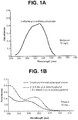
- FIG. 1A and FIG. 1B depict the ultraviolet-visible spectra of light-absorbing compounds that are suitable for use in the material comprising the light-transmitting region of the invention.
- the data shown in FIG. 1A and FIG. 1B were acquired from the manufacturers of the light-absorbing compounds.
- FIG. 1A is an ultraviolet-visible spectrum of 2-ethylhexyl-p-methoxycinnamate (e.g., UVINULTM 3088) in methanol at a concentration of 10 mg/L (1 cm path length), which reveals an absorbance of 0.42 or less in the range of at least 250 nm to 350 nm and a maximum light absorption located at 310 nm.
- FIG. 1A is an ultraviolet-visible spectrum of 2-ethylhexyl-p-methoxycinnamate (e.g., UVINULTM 3088) in methanol at a concentration of 10 mg/L (1 cm path length), which reveals an absorbance of 0.42 or less in the range of at least
- FIG. 1B depicts overlaid ultraviolet-visible spectra of separate solutions of 2-hydroxy-4-n-octoxybenzophenone (e.g., CYASORBTM UV-531) and 2-(4,6-bis-(2,4-dimethylphenyl)-1,3,5-triazin-2-yl)-5-(octyloxy)-phenol (e.g., CYASORBTM UV-1164) in toluene at a concentration of 10 mg/L.
- CYASORBTM UV-531 2-hydroxy-4-n-octoxybenzophenone
- CYASORBTM UV-531 has an absorbance of 0.5 or less in a range of 290 nm to 410 nm and a maximum light absorption located at 325 nm
- CYASORBTM UV-1164 has an absorbance of 0.5 or less in a range of 310 nm to 410 nm and a maximum light absorption located at 340 nm.
- the spectrum of UVINULTM 3088 in FIG. 1A , and the overlaid spectra of CYASORBTM UV-531 and CYASORBTM UV-1164 in FIG. 1B reveal that all three of these light-absorbing compounds can be suitably used in the material comprising the light-transmitting region of the invention.
- the one or more light-absorbing compounds can be employed in the material comprising the light-transmitting region in any suitable amount.
- the amount of light-absorbing compound included in the light-transmitting region of the invention depends, in part, on the location of the maximum absorbance and/or molar absorptivity of the light-absorbing compound.
- the one or more light-absorbing compounds can be incorporated into the material comprising the light-transmitting region in an amount of 0-05%) to 20% by weight based on the weight of the light-transmitting region.
- the one or more light-absorbing compounds can be incorporated into the material comprising the light-transmitting region in an amount of 0.05% or more, e.g., 0 , 1% or more, 0.15% or more, 0.2% or more, 0.25% or more, 0.3% or more, 0.35% or more, 0.4% or more, 0.45% or more, 0.5% or more, 0.55% or more, 0.6% or more, 0.65% or more, 0.7% or more, 0.75% or more, 0,8% or more, 0.85% or more, 0.9% or more, 0.95% or more, 1.1% or more, 1.2% or more, 1,3% or more, 1.4% or more, 1.5% or more, 1.6% or more, 1.7% or more, 1.8% or more, 1.9% or more, 2%) or more, 2.5%) or more, 3% or more, 3.5% or more, 4% or more, 4.5% or more, 5% or more, 5.5% or more, 6% or more, 6,5% or more, 7% or more, 7.5% or more, 8% or more, 8.5%
- the one or more light-absorbing compounds can be incorporated into the material comprising the light-transmitting region in an amount of 20% or less, e.g., 19% or less, 18% or less, 17% or less, 16% or less, 15% or less, 14% or less, 13% or less, 12% or less, 11% or less, 10% or less, 9.5% or less, 9% or less, 8.5% or less, 8% or less, 7.5% or less, 7% or less, 6.5% or less, 6% or less, 5.5% or less, 5% or less, 4.5% or less, 4% or less, 3.5% or less, 3% or less, 2.5% or less, 2% or less, 1.9% or less, 1.8% or less, 1.7% or less, 1.6% or less, 1.5% or less, 1.4% or less, 1.3%, or less, 1.2% or less, 1.1 % or less, 1% or less, 0.95% or less, 0.9% or less, 0.85%, or less, 0.8% or less, 0,75% or less, 0.
- the one or more light-absorbing compounds can be incorporated into the material comprising the light-transmitting region in amounts bounded by any two of the foregoing endpoints.
- the one or more light-absorbing compounds can be incorporated into the material comprising the light-transmitting region in amounts of 0.05% to 1.5%, 1% to 5%, or 4.5%) to 11 % by weight based on the weight of the light-transmitting region.
- the foregoing recited amounts refer to the total amount of light-absorbing compound present in the material comprising light region.
- Light-absorbing compounds typically will significantly absorb light and/or have a maximum absorption located in a wavelength range that makes it difficult for polishing pads containing these unsuitable compounds to be suitably used with white light endpoint detection systems.
- Examples of light-absorbing compounds that are not suitable for use with the invention include hindered amine light stabilizers (i.e., HALS), 2-(2-hydmxy-5-methylphenyl)benzotriazole (e.g., TINIUVINTM P), 2-(2H-benzotriazol-2-yl)-4,6-ditertpentylphenol (e.g., TINUVINTM 328), etc.
- HALS hindered amine light stabilizers
- 2-(2-hydmxy-5-methylphenyl)benzotriazole e.g., TINIUVINTM P
- 2-(2H-benzotriazol-2-yl)-4,6-ditertpentylphenol e.g., TINUVINT
- the material comprising the light-transmitting region of the invention does not contain any of these unsuitable light-absorbing compounds.
- Two types of light-absorbing compounds that are not suitable for use in the material of the light-transmitting region of the invention are depicted below and include certain types of benzotriazoles and benzophenones.
- the substituent R is typically hydrogen, an alkyl group (e.g., methyl, ethyl, propyl, butyl, and pentyl), an ester, etc.
- the substituents R 1 and R 2 can be the same or different and typically include hydrogen, an alkyl group (e.g., methyl, ethyl, propyl, isopropyl, n-butyl, tert-butyl, isobutyl, sec-butyl, n-pentyl, tert-pentyl, sec-pentyl, etc.), a hydroxyl group, a halogen (e.g., fluoro, chloro, promo, iodo, etc.), or an ester.
- an alkyl group e.g., methyl, ethyl, propyl, isopropyl, n-butyl, tert-butyl, isobutyl, sec-butyl, n-pentyl, tert-pentyl, sec-pentyl, etc.
- a halogen e.g., fluoro, chloro, promo, i
- FIG. 2 depicts the ultraviolet-visible spectrum of a light-absorbing compound that is not suitable for use in the material comprising the light-transmitting region of the invention.
- the data shown in FIG. 2 was obtained from the manufacturer of the light-absorbing compound.
- FIG. 2 is an ultraviolet-visible spectrum of 2-(2-hydroxy-5-methylphenyl)benzotriazole (e.g., TINUVINTM P) in chloroform at a concentration of 10 mg/L, which reveals this light-absorbing compound to have an absorbance of 0.5 or less in a range of 250 nm to 288 nm and 360 nm to 500 nm and two maximum light absorptions of similar intensity located at 301 and 341 nm.
- the spectrum in FIG. 2 reveals that this light-absorbing compound is unsuitable for use in the material comprising the light-transmitting region of the invention.
- the light-transmitting region is discolored 45% or less at one or more wavelengths in a range of 395 nm to 800 nm upon ultraviolet light irradiation, as measured according to ASTM D1148-95, hereby incorporated by reference in its entirely.
- the light-transmitting region is discolored 40% or less, 35% or less, 30% or less, 25% or less, 20% or less, 15% or less, 10% or less, 5% or less, or 0% at one or more wavelengths in a range of 395 nm to 800 nm upon ultraviolet light irradiation, as measured according to ASTM D1148-95.
- the degree of discoloration (%) of the light-transmitting region recited herein for the range of 395 nm to 800 nm as measured by ASTM D1148-95 is applicable to any one or more wavelengths within the range of 395 nm to 800 nm, including individual wavelengths (e.g., 395 nm, 400 nm, 410 nm, 420 nm, 430 nm, 440 nm, 450 nm, 460 nm, 470 nm, 480 nm, 490 nm, 500 nm, 520 nm, 540 nm, 560 nm, 580 nm, 600 nm, 620 nm, 640 nm, 660 nm, 680 nm, 700 nm, 720 nm, 740 nm, 760 nm, 780 nm, or 800 nm) and ranges of wavelengths within the range of 395 nm to 800
- the degree of discoloration (%) of the light-transmitting region as recited herein can be within the range of 395 nm or more, e.g., 400 nm or more, 410 nm or more, 420 nm or more, 430 nm or more, 440 nm or more, 450 nm or more, 460 nm or more, 470 nm or more, 480 nm or more, 490 nm or more, 500 nm or more, 510 nm or more, 520 nm or more, 530 nm or more, 540 nm or more, 550 nm or more, 560 nm, or more, 570 nm or more, 580 nm or more, 590 nm or more, 600 nm or more, 610 nm or more, 620 nm or more, 630 nm or more, 640 nm or more, 650 nm or more, 660 n
- the degree of discoloration (%) of the light-transmitting region as recited herein can be within the range of 800 nm or less, e,g., 790 nm or less, 780 nm or less, 770 nm or less, 760 nm or less, 750 nm or less, 740 nm or less, 730 nm or less, 720 nm or less, 710 nm or less, 700 nm or less, 690 nm or less, 680 nm or less, 670 nm or less, 660 nm or less, 650 nm or less, 640 nm or less, 630 nm or less, 620 nm or less, 610 nm or less, 600 nm or less, 590 nm or less, 580 nm or less, 570 nm or less, 560 nm or less, 550 nm or less, 540 nm or less,
- the degree of discoloration (in %) of the light-transmitting region as recited herein can be bounded by any two of the foregoing endpoints.
- the degree of discoloration of the light-transmitting region can be 45% or less in a range of 395 nm to 800 nm, 25% or less in a range of 410 nm to 480 nm, or 40% or less in a range of 450 nm to 550 nm.
- any of the individual wavelengths can be combined with any of the wavelength ranges when describing the degree of discoloration of the light-transmitting region.
- the polishing pad body typically is porous and has a first void volume (i.e., porosity).
- the first void volume typically is non-zero and can be any suitable non-zero void volume.
- the first void volume can be 0,1% or more, e.g., 0.2% or more, 0.3% or more, 0.4% or more, 0.5%.
- the first void volume can be 80% or less, e.g., 75% or less, 70% or less, 65% or less, 60% or less, 55% or less, 50% or less, 45% or less, 40% or less, 35% or less, 30% or less, 25% or less, 20% or less, 15% or less, 10% or less, 9% or less, 8% or less, 7% or less, 6% or less, 5% or less, 4% or less, 3% or less, 2% or less, 1% or less, 0.9% or less, 0.8% or less, 0.7% or less, 0.6% or less, 0.5% or less, 0.4% or less, 0.3% or less, or 0.2% or less.
- the first void volume can be bounded by any two of the foregoing endpoints.
- the first void volume can be 0.1% to 80%, 20% to 50%, or 65% to 70%.
- the polishing pad body can comprise pores of any suitable average pore size.
- the term "average pore size" refers to the average pore diameter.
- the pores of the polishing pad body can have an average pore size of 1000 ⁇ m or less, e.g., 900 ⁇ m or less, 800 ⁇ m or less, 700 ⁇ m or less, 600 ⁇ m or less, 500 ⁇ m or less, 400 ⁇ m or less, 300 ⁇ m or less, 200 ⁇ m or less, 190 ⁇ m or less, 180 ⁇ m or less, 170 ⁇ m or less, 160 ⁇ m or less, 150 ⁇ m or less, 140 ⁇ m or less, 130 ⁇ m or less, 120 ⁇ m or less, 110 ⁇ m or less, 100 ⁇ m or less, 90 ⁇ m or less, 80 ⁇ m or less, 70 ⁇ m or less, 60 ⁇ m or less, 50 ⁇ m or less, 40 ⁇ m or less, 30 ⁇ m or less, 20 ⁇ m or less,
- the pores of the polishing pad body can have an average pore size of 1 ⁇ m or more, e.g., 5 ⁇ m or more, 10 ⁇ m or more, 20 ⁇ m or more, 30 ⁇ m or more, 40 ⁇ m or more, 50 ⁇ m or more, 60 ⁇ m or more, 70 ⁇ m or more, 80 ⁇ m or more, 90 ⁇ m or more, 100 ⁇ m or more, 110 ⁇ m or more, 120 ⁇ m or more, 130 ⁇ m or more, 140 ⁇ m or more, 150 ⁇ m or more, 160 ⁇ m or more, 170 ⁇ m or more, 180 ⁇ m or more, 190 ⁇ m or more, 200 ⁇ m or more, 300 ⁇ m or more, 400 ⁇ m or more, 500 ⁇ m or more, 600 ⁇ m or more, 700 ⁇ m or more, 800 ⁇ m or more, or 900 ⁇ m or more.
- the pores of the polishing pad body can have an average pore size bounded by any two of the foregoing endpoints.
- the average pore size can be 1 ⁇ m to 5 ⁇ m, 50 ⁇ m to 110 ⁇ m, or 180 ⁇ m to 600 ⁇ m.
- a substantial portion (e.g., 50% or more) of the pores of the polishing pad body have a pore size of 200 ⁇ m or less.
- a substantial portion (e.g., 50% or more) of the pores of the polishing pad body have a pore size of 200 ⁇ m or less.
- 55% or more, e.g., 60% or more, 65% or more, 70% or more, 75% or more, 80% or more, 8-5% or more, 90% or more, 95% or more, or 100% of the pores have a pore size of 200 ⁇ m or less.
- the polishing pad body comprises predominantly closed cells (i.e., pores).
- the polishing pad body can also comprise open cells.
- the polishing pad body comprises a void volume of closed cells of 5% or more, e.g., 10% or more, 15% or more, 20% or more, 25% or more, 30% or more, 35% or more, 40% or more, 45% or more, 50% or more, 60% or more, 70% or more, 80% or more, 90% or more, or 100% based on the total void volume of the polishing pad body.
- the light-transmitting region has a second void volume (i.e., porosity) (as distinguished from the first void volume of the polishing pad body) and can be porous, substantially non-porous, or completely non-porous (i.e., 0% void volume).
- the second void volume of the light-transmitting region typically is smaller than the first void volume of the polishing pad body.
- the second void volume can be 0% or more, e.g., 0.05% or more, 0.1% or more, 0.15% or more, 0.2% or more, 0.25% or more, 0.3% or more, 0.35% or more, 0.4% or more, 0.45% or more, 0.5% or more, 0.55% or more, 0.6% or more, 0.65% or more, 0.7% or more, 0.75% or more, 0.8% or more, 0.85% or more, 0.9% or more, 0.95% or more, 1% or more, 1.1% or more, 1.2% or more, 1.3% or more, 1.4% or more, 1.5% or more, 1.6% or more, 1.7% or more, 1.8% or more, 1.9% or more, 2% or more, 2.5% or more, 3% or more, 3.5% or more, 4% or more, 4.5% or more, 5% or more, 5.5% or more, 6% or more, 6.5% or more, 7% or more, 7.5% or more, 8% or more, 8.5% or more, 9% or more, or 9.5% or more.
- the second void volume can be 10% or less, e.g., 9.5% or less, 9% or less, 8.5% or less, 8% or less, 7.5% or less, 7% or less, 6.5% or less, 6% or less, 5.5% or less, 5% or less, 4.5% or less, 4% or less, 3.5% or less, 3% or less, 2.5% or less, 2% or less, 1.9% or less, 1.8% or less, 1.7% or less, 1.6% or less, 1.5% or less, 1.4% or less, 1.3% or less, 1.2% or less, 1.1% or less, 1% or less, 0.95% or less, 0.9% or less, 0.85% or less, 0.8% or less, 0.75% or less, 0.7% or less, 0.65% or less, 0.6% or less, 0.55% or less, 0.5% or less, 0.45% or less, 0.4% or less, 0.35% or less, 0.3% or less, 0.25% or less, 0.2% or less, 0.15% or less, 0.1% or less, or 0.05% or
- the second void volume of the light-transmitting region can be bounded by any two of the foregoing endpoints.
- the second void volume can be 0.1% to 10%, 0.05% to 1.9%, or 0.5% to 1%.
- the second void volume is 0%.
- the pores can have any suitable average pore size.
- the term "average pore size" refers to the average pore diameter.
- the pores of the light-transmitting region can have an average pore size of 200 ⁇ m or less, e.g., 100 ⁇ m or less, 90 ⁇ m or less, 80 ⁇ m or less, 70 ⁇ m or less, 60 ⁇ m or less, 50 ⁇ m or less, 40 ⁇ m or less, 30 ⁇ m or less, 20 ⁇ m or less, 10 ⁇ m or less, 5 ⁇ m or less, 1 ⁇ m or less, 0.9 ⁇ m or less, 0.8 ⁇ m or less, 0.7 ⁇ m or less, 0.6 ⁇ m or less, 0.5 ⁇ m or less, 0.4 ⁇ m or less, 0.3 ⁇ m or less, 0.2 ⁇ m or less, 0.1 ⁇ m or less, or 0.05 ⁇ m or less.
- the pores of the light-transmitting region can have an average pore size of 0.01 ⁇ m or more, e.g., 0.05 ⁇ m or more, 0.1 ⁇ m or more, 0.2 ⁇ m or more, 0.3 ⁇ m or more, 0.4 ⁇ m or more, 0.5 ⁇ m or more, 0.6 ⁇ m or more, 0.7 ⁇ m or more, 0.8 ⁇ m or more, 0.9 ⁇ m or more, 1 ⁇ m or more, 5 ⁇ m or more, 10 ⁇ m or more, 20 ⁇ m or more, 30 ⁇ m or more, 40 ⁇ m or more, 50 ⁇ m or more, 60 ⁇ m or more, 70 ⁇ m or more, 80 ⁇ m or more, 90 ⁇ m or more, or 100 ⁇ m or more.
- the average pore size of the pores comprising the light-transmitting region can be bounded by any two of the foregoing endpoints.
- the average pore size can be 0.05 ⁇ m to 1 ⁇ m, 0.2 ⁇ m to 0.8 ⁇ m, or 10 ⁇ m to 100 ⁇ m.
- a substantial portion (e.g., 50% or more) of the pores of the light-transmitting region have a pore size of 1 ⁇ m or less.
- 55% or more, e.g., 60% or more, 65% or more, 70% or more, 75% or more, 80% or more, 85% or more, 90% or more, 95% or more, or 100%) of the pores have a pore size of 1 ⁇ m or less.
- the light-transmitting region(s) comprises predominantly closed cells (i.e., pores). However, the light-transmitting can also comprise open cells.
- the light-transmitting region(s) comprises a void volume of closed cells of 5% or more, e.g., 10% or more, 15% or more, 20% or more, 25% or more, 30% or more, 35% or more, 40% or more, 45% or more, 50% or more, 60% or more, 70% or more, 80% or more, 90% or more, or 100% based on the total void volume of the light-transmitting region(s).
- the polishing pad body typically is substantially or entirely opaque. Without wishing to be bound by any particular theory, it is believed that the pores in the polishing pad body cause light passing through the porous structure to scatter, thereby reducing the translucency of the polishing pad body or rendering the polishing pad body opaque. The degree of light scattering is believed to be a function of average pore size and average pore volume. It is further believed that compressing the polishing pad reduces the light-scattering effect of the pores by reducing the porosity (e.g., void volume) of the polishing pad in the region that is compressed.
- porosity e.g., void volume
- the compressed region e.g., a light transmitting region of the polishing pad
- has an increased light transmittance i.e., decreased level of light scattering and increased translucence
- the polishing pad that is not compressed i.e., the polishing pad body
- the degree of translucence provided in this manner will depend, at least in part, on the degree to which the porous structure is compressed (i.e., the degree to which the porosity of the porous structure is reduced).
- the polishing pad body can be compressed by 10-50% (e.g., 20-40%, or 10-30%) of its thickness prior to compression (i.e., the non-compressed thickness of the polishing pad).
- the material comprising the polishing pad body can be the same as or different from the material comprising the light-transmitting region(s).
- the material comprising the polishing pad body can be comprised of any polymer material that is compatible with chemical-mechanical polishing.
- the material comprising the polishing pad body can be selected from the polymers recited herein for use in the light-transmitting region(s), the polymers recited herein that are not preferred for use in the light transmitting region (i.e., so called "non-preferred" polymers), or any combination thereof.
- Suitable polymers for the polishing pad body include, for example, thermoplastic elastomers, thermoplastic polyurethanes, polyolefins, polycarbonates, polyvinylacohols, nylons, elastomeric rubbers, styrenic polymers, polyaromatics, fluoropolymers, pohimides, cross-linked polyurethanes, cross-linked polyolefins, polyethers, polyesters, polyacrylates, elastomeric polyethylenes, polytetrafluoroethylenes, polyethyleneteraphthalates, polyimides, polyaramides, polyarylenes, polystyrenes, polymethylmethacrylates, copolymers and block copolymers thereof, and mixtures and blends thereof.
- the polymer resin is thermoplastic polyurethane, such as a methylenediphenyl diisocyanate-based thermoplastic polyurethane.
- the polymeric resin (e.g., polymeric material) comprising the material of the light-transmitting region and/or the polishing pad body can have any suitable molecular weight.
- the molecular weight of the polymeric resin determines, in part, the theological properties of the polymeric resin, such that the molecular weight of the polymeric resin is important for the forming (e.g., extrusion, injection molding , etc.) properties of polymeric resin.
- the molecular weight of the polymeric resin comprising the light-transmitting region and/or polishing pad body can be 50,000 g/mol to 300,000 g/mol.
- the molecular weight can be 50,000 g/mol or more, e.g., 60,000 g/mol or more, 70,000 g/mol or more, 80,000 g/mol or more, 90,000 g/mol or more, 100,000 g/mol or more, 120,000 g/mol or more, 140,000 g/mol or more, 160,000 g/mol or more, 180,000 g/mol or more, 200,000 g/mol or more, 220,000 g/mol or more, 240,000 g/mol or more, 260,000 g/mol or more, or 280,000 g/mol or more.
- the molecular weight can be 300,000 g/mol or less, e.g., 280,000 g/mol or less, 260,000 g/mol or less, 240,000 g/mol or less, 220,000 g/mol or less, 200,000 g/mol or less, 180,000 g/mol or less, 160,000 g/mol or less, 140,000 g/mol or less, 120,000 g/mol or less, 100,000 g/mol or less, 90,000 g/mol or less, 80,000 g/mol or less, 70,000 g/mol or less, or 60,000 g/mol or less.
- the molecular weight of the polymeric resin comprising the material of the light-transmitting region and/or polishing pad body can be bounded by any two of the foregoing endpoints.
- the molecular weight can be 50,000 g/mol to 80,000 g/mol, 70,000 g/mol to 220,000 g/mol, or 60,000 g/mol to 70,000 g/mol.
- the polymeric resin (e.g., polymeric material) comprising the material of the light-transmitting region and/or the polishing pad body can have any suitable polydispersity index (PDI).
- the PDI of the polymeric resin determines, in part, the rheological properties of the polymeric resin, such that the PDI of the polymeric resin is important for the forming (e.g., extrusion, injection molding, etc.) properties of polymeric resin.
- the PDI of the polymeric resin is typically 1.1 to 6, preferably 2 to 4.
- the polishing pad, polishing pad body, and/or light-transmitting region(s) can be formed by any suitable technique known in the art.
- the polishing pad, polishing pad body, and/or light-transmitting region(s) can be formed by film or sheet extrusion, injection molding, blow molding, thermoforming, compression molding, co-extrusion molding, reaction injection molding, profile extrusion, molding, rotational molding, gas injection molding, film insert molding, foaming, casting, compression, or any combination thereof.
- the polishing pad, polishing pad body, and/or light-transmitting region(s) are made of, for example, a thermoplastic material (e.g., thermoplastic polyurethane)
- the thermoplastic material can be heated to a temperature at which it will flow and is then formed into a desired shape by, for example, casting or extrusion.
- the light-transmitting region of the polishing pad can be formed, for example, by compressing at least a portion of the polishing pad, which is substantially or entirely opaque, to form one or more light-transmitting region(s) of the polishing pad that are optically transmissive.
- optically transmissive refers to the ability to transmit at least a portion of light contacting the surface of the polishing pad and can be used to describe slightly, partially, substantially, and completely translucent or transparent materials.
- the compressed, optically transmissive region of the polishing pad body is a light-transmitting region of the invention having the properties described herein.
- Compression of the polishing pad to form a light-transmitting region can be performed in any suitable manner known in the art. See, e.g., U.S. Patent 6,840,843 .
- the most effective technique of compression will depend, at least in part, on the particular polymer(s) (e.g., polymeric resins) used in the fabrication of the polishing pad.
- the polishing pad can be compressed, for example, by use of radio frequency (RF) welding techniques, by use of calendar rollers, or by use of various pressing mechanisms known in the art, such as a platen press, stamping machine, and the like.
- RF radio frequency
- heat can be used, either alone or in conjunction with other compression techniques, to achieve a compressed structure.
- the polishing pad can be heated to a temperature approaching, meeting, or exceeding its softening or melting temperature for a time sufficient to allow the pores of the polishing pad body to collapse under the weight of the polymer used in the construction of the polishing pad body.
- heat can be applied to the polishing pad before, during, or after compressing of the polishing pad using another compression technique.
- an RF welding process can use a die or dies in conjunction with application of radiofrequency energy in the megahertz region to cause heating of the polishing pad that is in contact with the die or dies to cause compression of the polishing pad.
- a heated press or heated rollers can be used to compress the polishing pad so as to compress a region of the polishing pad.
- the polishing pad is preferably heated to a temperature that approaches, meets, or exceeds the softening or melting temperature of the polishing pad.
- the light-transmitting region(s) When the light-transmitting region(s) is not formed by compressing at least a portion of the polishing pad, the light-transmitting region(s) can be produced separately and then attached to the polishing pad body by any suitable technique known in the art. In such a situation, the material comprising the light-transmitting region can be the same or different from the material comprising the polishing pad body. Typically, a portion of the polishing pad is removed therefrom, so as to obtain a polishing pad body containing an empty void.
- the light-transmitting region(s) can be produced separately by any suitable technique, as described elsewhere herein, and then the light-transmitting region can be conformed, e.g., trimmed, to match the size of the void in the polishing pad body.
- the conformed light-transmitting region can then be placed in the void and attached to the polishing pad body by a suitable process, such as a process selected from the group consisting of a heat-melting chemical bond fusion, ultrasonic welding (see, e.g., U.S. Patent 6,997,777 , radio frequency (RF) welding, arc welding, heat compression, frictional heating, and combinations thereof.
- a suitable process such as a process selected from the group consisting of a heat-melting chemical bond fusion, ultrasonic welding (see, e.g., U.S. Patent 6,997,777 , radio frequency (RF) welding, arc welding, heat compression, frictional heating, and combinations thereof.
- RF radio frequency
- RF welding can involve positioning a light-transmitting region to be welded to the polishing pad and using a die to direct the welding process.
- High frequency waves in the megahertz frequency range are passed through the materials with the result that the pieces are heated, and the light-transmitting region(s) becomes attached to the polishing pad.
- Ultrasonic welding can involve the use of high frequency sound waves to melt the comprising, the right-transmitting region(s) and the polishing pad, thereby causing the materials to flow together so that the light-transmitting region(s) becomes attached to the polishing pad.
- the source of ultrasonic waves is a sound-generating metal tuning device (e,g., a "horn") that converts a high frequency electrical signal into sound in the kilohertz frequency range, although any suitable source of ultrasonic sound can be used.
- the horn can be any suitable horn, for example, a stainless steel hom.
- the horn can have any suitable shape or configuration and preferably is machined to have a similar shape, or even an identical shape, to the shape of the light-transmitting region(s).
- the polishing pad can comprise one or more light-transmitting regions, each of which can be prepared in the same or different manner (e.g., one region formed by compression, and one region produced separately and then welded to the polishing pad) and/or each of which can be comprised of the same or different material(s) (e.g., different polymeric resins and/or light-absorbing compounds).
- the polishing pad can comprise one, two, three, four, five, six, seven, eight, nine, or ten light-transmitting regions.
- the light-transmitting region(s) can comprise a portion of the polishing pad, or the light-transmitting region(s) can comprise the entire polishing pad.
- the light-transmitting region(s) can comprise 5% or more, e.g., 10% or more, 15% or more, 20% or more, 25% or more, 30% or more, 35% or more, 40% or more, 45% or more, 50% or more, 55% or more, 60% or more, 65% or more, 70% or more, 75% or more, 80% or more, 85% or more, 90% or more, 95% or more, or 100% of the polishing pad by surface area.
- the light-transmitting region(s) can comprise 100% or less, e.g., 95% or less, 90% or less, 85% or less, 80%- or less, 75% or less, 70% or less, 65% or less, 60% or less, 55% or less, 50% or less, 45% or less, 40% or less, 35% or less, 30% or less, 25% or less, 20% or less, 15% or less, or 10% or less of the polishing pad by surface area.
- the portion of the polishing pad comprised by the light-transmitting region can be bounded by any two of the foregoing endpoints.
- the light-transmitting region can comprise 10% to 35%, 30 % to 55%, or 60% to 95% of the polishing pad by surface area.
- the polishing pad comprises one light-transmitting region, in which the light-transmitting region does not comprise the entire polishing pad.
- the polishing pad comprises one light-transmitting region, in which the entire polishing pad (i.e., 100% by surface area) is a light-transmitting region, i.e., the entire polishing pad is composed of a material suitable for use as a light-transmitting region, which material has been suitably processed (e.g., compressed, extruded, and/or molded) so as to have the properties recited herein for the light-transmitting region.
- the light-transmitting region(s) can be positioned in any suitable location of the polishing pad, and the light-transmitting region(s) can have any suitable shape, dimension, or configuration.
- the light-transmitting region(s) can have the shape of a circle, an oval, a rectangle, or a square.
- the light-transmitting region(s) typically has a maximum length of 3 cm to 8 cm.
- the region(s) typically has a diameter or width of 1 cm to 4 cm.
- the light-transmitting region(s) can have any suitable thickness.
- the light-transmitting region(s) has a thickness of 0.2 mm or more, e.g., 0.3 mm or more, 0.4 mm or more, 0.5 mm or more, 0,6 mm or more, 0.7 mm or more, 0.8 mm or more, 0.9 mm or more, 1 mm or more, 1.1 mm or more, 1.2 mm or more, 1.3 mm or more, 1.4 mm or more, 1.5 mm or more, 1.6 mm or more, 1.7 mm or more, 1.8 mm or more, 1.9 mm or more, 2 mum or more, 2.2 mm or more, 2.4 mm or more, 2.6 mm or more, or 2.8 mm or more.
- the light-transmitting region(s) has a thickness of 3 mm or less, e.g., 2.8 mm or less, 2.6 mm or less, 2.4 mm or less, 2.2 mm or less, 2 mm or less, 1.9 mm or less, 1.8 mm or less, 1.7 mm or less, 1.6 mm or less, 1.5 mm or less, 1.4 mm or lest, 1.3 mm or less, 1.2 mm or less, 1.1 mm or less, 1 mm or less, 0.9 mm or less, 0.8 mm or less, 0.7 mm or less, 0.6 mm or less, 0.5 mm or less, 0.4 mm or less, or 0.3 mm or less.
- the thickness of the light-transmitting region(s) can be bounded by any two of the foregoing endpoints.
- the thickness of the light-transmitting region can be 0.2 to 3 mm, 0,2 mm to 1 mm, or 0.5 mm to 1.6 mm. In a preferred embodiment, the thickness of the light transmitting region is 1 mm.
- the material comprising the light-transmitting region which material is composed of at least one polymeric resin and at least one light-absorbing compounds, can be formed in any suitable manner.
- a light-absorbing compound can be added to this polymerisation medium prior to, during, or after polymerization, so as to form a polymeric resin with a light-absorbing compound dispersed therein.
- the polymeric resin can be either purchased commercially or synthesized using conventional polymerization techniques (e.g., condensation polymerization), and then both the polymeric resin and light-absorbing compound can be dissolved in a suitable solvent (e.g., an organic solvent such as tetrahydrofuran).
- a suitable solvent e.g., an organic solvent such as tetrahydrofuran.
- the solution containing the polymeric resin and light-absorbing compound can be subjected to reduced pressure and/or heat in order to remove the solvent, thereby obtaining a polymeric resin with a light-absorbing compound dispersed therein.
- a pro-synthesized and/or commercially purchased polymeric resin and a light-absorbing compound can be melt blended together, which technique comprises heating the polymeric resin to a sufficient temperature so as to melt the polymer.
- a light-absorbing compound can be added prior to, during, or after the polymeric resin has melted, so as to obtain a polymeric resin with a light-absorbing compound dispersed therein
- the polymer resin comprising the polishing pad body and/or light-transmitting region(s) may provide a porous structure by virtue of their natural configuration.
- the porous structure may be introduced through the use of various production techniques known in the art (e.g., foaming, blowing, and the like).
- Representative methods providing a porous structure comprising closed-cell pores include foaming processes such as a Mucell process, a phase inversion process, a spinodal or binodal decomposition process, or a pressurized gas injection process, all of which are well-known in the art.
- a representative method providing a porous structure comprising open-cell pores comprises sintering particles of a thermoplastic polymer, such as a thermoplastic polyurethane, to provide an open-cell porous structure.
- the polishing pad can have any suitable dimensions.
- the polishing pad is circular in shape (as is used in rotary polishing tools) or is produced as a looped linear belt (as is used in linear polishing tools).
- the polishing pad is circular.
- the light-transmitting region(s) and/or polishing pad body can have one or more of the following properties: (a) a Shore hardness of 10 A to 80 D, (b) a porosity in which the pores can have a certain size and proportion (as already described herein), (c) a % elongation of greater than 50%, (d) an ultimate tensile strength of greater than 65 kPa, (e) a flexural modulus at room temperature of 700 kPa to 3,500,000 kPa, (f) a resin melt index or melt flow rate of less than 500 g/10 min at 2160 g load at 210 °C, (g) a resin melt viscosity range of 10 Pa ⁇ s to 20,000 Pa ⁇ s., as measured by a capillary rheometer at a shear rate of 18/s at 210 °C, (h) a % crystallinity, (i) a glass transition temperature of about -100°C to 160 °C, (j
- the foregoing properties will determine, in part, the rheological properties of the polymeric resin, which properties are important for ensuring that the polymer can be suitably molded (e.g., extruded or injection molded) into a polishing pad body and/or light-transmitting region.
- the foregoing properties are also important for determining the structural properties of the polishing pad body and/or light-transmitting region, to ensure, for example, that the polishing pad can be suitably used in chemical-mechanical polishing.
- the foregoing properties ensure that a polishing pad is compatible with polishing compositions, can withstand physical and chemical abrasion, and can suitably abrade and planarize a substrate surface.
- the light-transmitting region(s) and/or polishing pad body typically are formed from a polymeric resin.
- the light-transmitting region(s), polishing pad body, and/or polymeric resin can have any suitable Shore hardness.
- the Shore hardness depends, for example, on the material comprising the polishing pad and the method of producing the polishing pad. Both the Shore A and Shore D scales span from 0 to 100, are a measure of a material's hardness, and are measured according to ASTM D2240-10.
- the Shore A scale is typically used for relatively softer materials, whereas the Shore D scale is typically used for relatively harder materials; however, there is some overlap between the scales.
- the Shore A hardness of the light-transmitting region(s), polishing pad body, and/or polymeric resin can be 10 or more, e.g., 20 or more, 30 or more, 40 or more, 50 or more, 60 or more, 70 or more, 80 or more, or 90 or more.
- the Shore A hardness of the light-transmitting region(s), polishing pad body, and/or polymeric resin can be 100 or less, e.g., 90 or less, 80 or less, 70 or less, 60 or less, 50 or less, 40 or less, 30 or less, or 20 or less.
- the Shore D hardness of the light-transmitting region(s), polishing pad body, and/or polymeric resin can be greater than 0, e.g., 10 or more, 20 or more, 30 or more, 40 or more, 50 or more, 60 or more, or 70 or more.
- the Shore D hardness of the light-transmitting region(s), polishing pad body, and/or polymeric resin can be 80 or less, e.g., 70 or less, 60 or less, 50 or less, 40 or less, 30 or less, 20 or less, or 10 or less.
- the Shore hardness of the light-transmitting region(s), polishing pad body, and/or polymeric resin can be bounded by any two of the foregoing endpoints.
- the Shore hardness of the light-transmitting region(s), polishing pad body, and/or polymeric resin can be from 10 A to 50 A, 20 A to 50 D, or 20 D to 70 D.
- the light-transmitting region(s) and/or polishing pad body can have any suitable % elongation.
- the % elongation is measured according to ASTM D412-06a. The % elongation depends, for example, on the material comprising the polishing pad and the method of producing the polishing pad.
- the % elongation of the light-transmitting region(s) and or polishing pad body can be 50% or more, e.g., 60% or more, 80% or more, 100% or more, 120% or more, 140% or more, 160% or more, 180% or more, 200% or more, 220% or more, 240% or more, 260% or more, 280% or more, 300% or more, 320% or more, 340% or more, 360% or more, 380% or more, 400% or more, 500% or more, 600% or more, 700% or more, 800% or more, 900% or more, 1,000% or more. or 1,100% or more.
- the % elongation of the light-transmitting region(s) and/or polishing pad body can be 1,200% or less, e,g., 1,100% or less, 1,000% or less, 900% or less, 800% or less, 700% or less, 600% or less, 500% or less, 400% or less, 380% or less, 360% or less, 340% or less, 320% or less, 300% or less, 280% or less, 260% or less, 240% or less, 220% or less, 200% or less, 180% or less, 160% or less, 140% or less, 20%) or less, 100% or less, 80% or less, or 60% or less.
- the % elongation of the light-transmitting region(s) and/or polishing pad body can be bounded by any two of the foregoing endpoints.
- the % elongation of the light-transmitting region(s) and/or polishing pad body can be 60% to 180%, 100% to 120%, or 300% to 400%. In a preferred embodiment, the % elongation is 100% to 700%.
- the light-transmitting region(s) and/or polishing pad body can have any suitable ultimate tensile strength.
- the ultimate tensile strength depends, for example, on the material comprising the polishing pad and the method of producing the polishing pad.
- the ultimate tensile strength is measured according to ASTM D412-06a.
- the ultimate tensile strength of the light-transmitting region(s) and/or polishing pad body can be 65 kPa or more, e.g., 100 kPa or more, 200 kPa or more, 400 kPa, or more, 600 kPa or more, 800 kPa or more, 1,000 kPa, or more, 2,000 kPa or more, 3,000 kPa or more, 4,000 kPa or more, 5,000 kPa or more, 6,000 kPa or more, 7,000 kPa or more, 8,000 kPa or more, 9,000 kPa or more, 10,000 kPa, or more, 15,000 kPa or more, 20,000 kPa or more, 25,000 kPa, or more, 30,000 kPa or more, 35,000 kPa or more, 40,000 kPa, or more, 45,000 kPa or more, 50,000 kPa or more, 55,000 kPa or more
- the ultimate tensile strength of the light-transmitting region(s) and/or polishing pad body can be 1,000,000 kPa or less, e.g., 900,000 kPa, or less, 800,000 kPa, or less, 700,000 kPa or less, 600,000 kPa, or less, 500,000 kPa or lest, 400,000 kPa, or less, 300,000 kPa or less, 200,000 kPa or less, 100,000 kPa or less, 95,000 kPa or less, 90,000 kPa or less, 85,000 kPa or less, 80,000 kPa or less, 75,000 kPa or less, 70,000 kPa or less, 65,000 kPa or less, 60,000 kPa or less, 55,000 kPa or less, 50,000 kPa or less, 45,000 kPa or less, 40,000 kPa or less, 35,000 kPa or less, e.
- the ultimate tensile strength of the light-transmitting region(s) and/or polishing pad body can be bounded by any two of the foregoing endpoints.
- the ultimate tensile strength of the light-transmitting region(s) and/or polishing pad body can be 65 kPa to 1,000 kPa, 80 kPa to 200 kPa, or 45,000 kPa to 65,000 kPa.
- the ultimate tensile strength of the light-transmitting region(s) and/or polishing pad body is 10,000 kPa to 100,000 kPa.
- the light-transmitting region(s) and/or polishing pad body can have any suitable flexural modulus.
- the flexural modulus depends, for example, on the material comprising the polishing pad and the method of producing the polishing pad.
- the flexural modulus is measured according to ASTM D790-10.
- the flexural modulus of the light-transmitting region(s) and/or polishing pad body can be 700 kPa or more, e.g., 800 kPa or more, 900 kPa or more, 1,000 kPa or more, 2,000 kPa or more, 3,000 kPa or more, 4,000 kPa or more, 5,000 kPa or more, 10,000 kPa or more, 20,000 kPa, or more, 30,000 kPa or more, 40,000 kPa or more, 50,000 kPa or more, 100,000 kPa or more, 200,000 kPa or more, 300,000 kPa or more, 400,000 kPa or more, 500,000 kPa or more, 1,000,000 kPa, or more, 2,000,000 kPa or more, or 3,000,000 kPa or more.
- the flexural modulus of the light-transmitting region(s) and/or polishing pad body can be 3,500,000 kPa or less, e.g.. 3,000,000 kPa or less, 2,000,000 kPa or less, 1,000,000 kPa or less, 500,000 kPa or less, 400,000 kPa or less, 300,000 kPa or less, 200,000 kPa or less, 100,000 kPa or less, 50,000 kPa, or less, 40,000 kPa, or less, 30,000 kPa or less, 20,000 kPa or less, 10,000 kPa or less, 5,000 kPa or less, 4,000 kPa or less, 3,000 kPa or less, 2,000 kPa or less, 1,000 kPa or less, 900 kPa or less, or 800 kPa or less.
- the flexural modulus of the light-transmitting region(s) and/or polishing pad body can be bounded by any two of the foregoing endpoints.
- the flexural modulus of the light-transmitting region(s) and/or polishing pad body can be 700 kPa to 3,000 kPa, 2,000 kPa, to 50,000 kPa, or 10,000 kPa to 1,000,000 kPa.
- the material comprising the light-transmitting region(s) and/or polishing pad body can have any suitable resin melt index or melt flow rate.
- the resin melt index or melt flow rate depends, for example, on the material (e.g. the specific polymeric resin) comprising the polishing pad.
- the resin melt index or melt flow rate of a material e.g., polymeric resin
- provides a measure of the amount of material in grams flowing through an opening of a specifies diameter in a specified amount of time at a given temperature, and thus the resin melt index or melt flow rate is related to the viscosity of the material.
- the resin melt index or meet flow rate as recited herein is measured at a temperature of 210°C and a load of 2160 g.
- the melt index or melt flow rate of the light-transmitting region(s) and/or polishing pad body can be 10 g/10 min or more, e.g., 20 g/10 min or more, 30 g/10 min or more, 40 g/10 min or more, 50 g/10 min or more, 60 g/10 min or more, 70 g/10 min or more, 80 g/10 min or more, 90 g/10 min or more, 100 g/10 min or more, 150 g/10 min or more, 200 g/10 min or more, 250 g/10 min or more, 300 g/10 min or more, 350 g/10 min or more, 400 g/10 mm or more, or 450 g/10 min or more.
- the resin melt index or melt flow rate of the light-transmitting region(s) and/or polishing pad body can be 500 g/10 min or less, e.g., 450 g/10 min or lees, 400 g/10 min or less, 350 g/10 min or less, 300 g/10 min or less, 250 g/10 min or less, 200 g/10 min or less, 150 g/10 min or less, 100 g/10 min or less, 90 g/10 min or less, 80 g/10 min or less, 70 g/10 min or less, 60 g/10 min or less, 50 g/10 min or less, 40 g/10 min or less, 30 g/10 min or less, or 20 g/10 min or less.
- the resin melt index or melt flow rate of the light-transmitting region(s) and/or polishing pad body can be bounded by any two of the foregoing endpoints.
- the resin melt index or melt flow rate of the light-transmitting region(s) and/or polishing pad body can be 70 g/10 min to 350 g/10 min, 150 g/10 min to 400 g/10 min, or 100 g/10 min to 500 g/10 min.
- the light-transmitting region(s) and/or polishing pad body can have any suitable resin melt viscosity.
- the resin melt viscosity depends, for example, on the material comprising the polishing pad.
- the resin melt viscosity (Pa ⁇ s) is measured by a capillary rheometer at a shear rate of 18/s at a temperature of 210 °C.
- the resin melt viscosity of the light-transmitting region(s) and/or polishing pad body can be 10 Pa ⁇ s or more, e.g., 50 Pa ⁇ s or more, 100 Pa ⁇ s or more, 200 Pa ⁇ s or more, 300 Pa ⁇ s or more, 400 Pa ⁇ s or more, 500 Pa ⁇ s or more, 600 Pa ⁇ s or more, 700 Pa ⁇ s or more, 800 Pa ⁇ s or more, 900 Pa ⁇ s or more, 1,000 Pa ⁇ s or more, 2,000 Pa ⁇ s or more, 3,000 Pa ⁇ s or more, 4,000 Pa ⁇ s or more, 5,000 Pa ⁇ s or more, 6,000 Pa ⁇ s or more, 7,000 Pa ⁇ s or more, 8,000 Pa ⁇ s or more, 9,000 Pa ⁇ s or more, 10,000 Pa ⁇ s or more, 11,000 Pa ⁇ s or more, 12,000 Pa ⁇ s or more, 13,000 Pa ⁇ s or more, 14,000 Pa ⁇ s or more, 15,000 Pa ⁇ s or more, 16,000 Pa ⁇ s or more, 17,000 Pa ⁇ s or more, 18.000 Pa ⁇ s or more, or
- the resin melt viscosity of the light-transmstting region(s) and/or polishing pad body can be 20,000 Pa ⁇ s or less, e.g., 19,000 Pa ⁇ s or less, 18,000 Pa ⁇ s or less, 17,000 Pa ⁇ s or less, 16,000 Pa ⁇ s or less, 15,000 Pa ⁇ s or less, 14,000 Pa ⁇ s or less, 13,000 Pa ⁇ s or less, 12,000 Pa ⁇ s or less, 11,000 Pa ⁇ s or less, 10,000 Pa ⁇ s or less, 9,000 Pa ⁇ s or less, 8,000 Pa ⁇ s or less, 7,000 Pa ⁇ s or less, 6,000 Pa ⁇ s or less, 5,000 Pa ⁇ s or less, 5,000 Pa ⁇ s or less, 4,000 Pa ⁇ s or less, 3,000 Pa ⁇ s or less, 2,000 Pa ⁇ s or less, 1,000 Pa ⁇ s or less, 900 Pa ⁇ s or less, 800 Pa ⁇ sor less, 700 Pa ⁇ sor less 600 Pa ⁇ s or less, 500 Pa ⁇ s or less, 400 Pa ⁇ s or less, 300 Pa ⁇ or less, 200 Pa ⁇ s or less
- the resin melt viscosity of the light-transmitting region(s) and/or polishing pad body can be bounded by any two of the foregoing endpoints.
- the resin melt viscosity of the light-transmitting region(s) and/or polishing pad body can be 50 Pa ⁇ s to 3,000 Pa ⁇ s, 400 Pa ⁇ s to 2.000 Pa ⁇ s, or 15.000 Pa ⁇ s to 18,000 Pa ⁇ s.
- the light-transmitting region(s) can have any suitable % crystallinity.
- the % crystallinity depends, for example, on the material comprising the light-transmitting region(s) and the method of producing the light-transmitting region(s).
- the % crystallinity can be measured according to ASTM D3418-08.
- a high degree of crystallinity can prevent the light-transmitting region from possessing the light-transmitting properties recited herein, such that in general a lower degree of crystallinity is desirably.
- the % crystallinity of the light-transmitting region(s) can be greater than 0%, e.g., % or more, 2% or more, 4% or more, 6% or more, 8% or more, 10% or more, 1 2% or more, 14%) or more, 16% or more, 18% or more, 20% or more, 22% or more, 24% or more, 26% or more, or 28% or more.
- the % crystallinity of the light-transmitting region(s) can be 30% or less, e.g., 28% or less, 26% or less, 24% or less, 22% or lens, 20% or less, 18% or less, 16% or less, 14% or less, 12%, or less, 10% or less, 8% or less, 6% or less, 4% or less, 2% or less, or 1% or less.
- the % crystallinity of the light-transmitting region(s) can be bounded by any two of the foregoing endpoints
- the % crystallinity of the light-transmitting region(s) can be 1% to 10%, 4% to 22%, or 12% to 28%, depending, for example, on the desired light-transmitting properties of the light-transmitting region.
- the polishing pad body can have any suitable % crystallinity.
- the % crystallinity depends, for example, on the material comprising the polishing pad body and the method of producing the polishing pad body.
- the % crystallinity can be measured as described above with respect to the %) crystallinity of the light-transmitting region(s).
- the % crystallinity of the polishing pad body can be greater than 0%, e.g., 1% or more, 5% or more, 10% or more, 15% or more, 20% or more, 25% or more, 30% or more, 35% or more, 40% or more, 43% or more, 50% or more, or 55% or more.
- the % crystallinity of the polishing pad body can be 60% or less, e.g., 55% or less, 50% or less, 45% or less, 40% or less, 35% or less, 30% or less, 25% or less, 20% or less, 15% or less, 10% or less, 5% or less, or 1% or less.
- the % crystallinity of the polishing pad body can be bounded by any two of the foregoing endpoints.
- the % crystallinity of the polishing pad body can be 1% to 10%, 2% to 30%, or 25% to 45%, depending, for example, on the desired light-transmitting properties of the polishing pad body.
- the light-transmitting region(s) and/or polishing pad body can have any suitable glass transition (Tg) temperature.
- Tg glass transition temperature
- the glass transition temperature depends, for example, on the material comprising the polishing pad.
- the glass transition temperature can be measured by conventional techniques, such as differential scanning calorimetry (DSC).
- the glass transition temperature of the light-transmitting region(s) and/or polishing pad body can be about -100°C or more, e.g., about -90°C or more, about -80°C or more, about -70°C or more, about -60°C or more, about -50°C or more, about -40°C or more, about -30°C or more, about -20°C or more, about -10°C or more, 0°C or more, 10°C or more, 20°C or more, 30°C or more, 40°C or more, 50°C or more, 60°C or more, 70°C or more, 80°C or more, 90°C or more, 100°C or more, 110°C or more, 120°C or more, 130°C or more, 140°C or more, or 150°C or more.
- the glass transition temperature of the light-transmitting region(s) and/or polishing pad body can be 160°C or less, 150°C or less, 140°C or less, 130°C or less, 120°C or less, 110°C or less, 100°C or less, 90°C or less, 80°C or less, 70°C or less, 60°C or less, 50°C or less, 40°C or less, 30°C or less, 20°C or less, 10°C or less, 0°C or less, about -10°C or less, about -20% or less, about -30°C or less, about - 40°C or less, about -50°C or less, about -60°C or less, about -70°C or less, about -80°C or less, or about 90°C or less.
- the glass transition temperature of the light-transmitting region(s) and/or polishing pad body can be bounded by any two of the foregoing endpoints.
- the glass transition temperature of the light-transmitting region(s) and/or polishing pad body can be about -80°C to 10°C, 0°C to 70°C, or 110°C to 150°C.
- the light-transmitting region(s) and/or polishing pad body can have any suitable surface roughness.
- the surface roughness of the light-transmitting region(s) and/or polishing pad body can result from the nature of the material and/or the process used to form the light-transmitting region(s) and/or polishing pad body.
- the surface roughness can be additionally or alternatively adjusted to the desired level of surface roughness by any suitable technique, such as by grinding.
- the surface roughness is measured according to ISO4287.
- the surface roughness of the light-transmitting region(s) and/or polishing pad body can be 0.1 ⁇ m or more, e.g., 0.5 ⁇ m or more, 1 ⁇ m or more, 5 ⁇ m or more, 10 ⁇ m or more, 15 ⁇ m or more, 20 ⁇ m or more, 25 ⁇ m or more, 30 ⁇ m or more, 35 ⁇ m or more, 40 ⁇ m or more, 45 ⁇ m or more, 50 ⁇ m or more, 55 ⁇ m or more, 60 ⁇ m or more, 65 ⁇ m or more, 70 ⁇ m or more, 75 ⁇ m or more, 80 ⁇ m or more, 85 ⁇ m or more, 90 ⁇ m or more, or 95 ⁇ m or more.
- the surface roughness of the light-transmitting region(s) and/or polishing pad body can be 100 ⁇ m or less, e.g., 95 ⁇ m or less, 90 ⁇ m or less, 85 ⁇ m or less, 80 ⁇ m or less, 75 ⁇ m or less, 70 ⁇ m or less, 65 ⁇ m or less, 60 ⁇ m or less, 55 ⁇ m or less, 50 ⁇ m or less, 45 ⁇ m or less, 40 ⁇ m or less, 35 ⁇ m or less, 30 ⁇ m or less, 25 ⁇ m or less, 20 ⁇ m or less, 15 ⁇ m or less, 10 ⁇ m or less, 5 ⁇ m or less, 1 ⁇ m or less, or 0.5 ⁇ m or less.
- the surface roughness of the light-transmitting region(s) and/or polishing pad body can be bounded by any two of the foregoing endpoints.
- the surface roughness of the light-transmitting region(s) and/or polishing pad body can be 1 ⁇ m to 20 ⁇ m, 5 ⁇ m to 80 ⁇ m, or 30 ⁇ m to 60 ⁇ m.
- the light-transmitting regiou(s) and or polishing pad body can have any suitable refractive index.
- the refractive index of the light-transmitting region desirably is similar to the refractive index of the polishing slurry used with the polishing pad, such that reflections at the window/slurry interface are minimized.
- the refractive index can be measured by conventional techniques, such as by using a refractometer.
- the refractive index of the light-transmitting region(s) and/or polishing pad body can be 1.1 or more, e.g., 1.2 or more, 1.3 or more, 1.4 or more, 1.5 or more, 1.6 or more, 1.7 or more, 1.8 or more, or 1.9 or more.
- the refractive index can be 2.0 or less, e.g., 1.9 or less, 1.8 or less, 1.7 or less, 1.6 or less, 1.5 or less, 1.4 or less, 1.3 or less, or 1.2 or less.
- the refractive index of the light-transmitting region(s) and/or polishing pad body can be bounded by any two of the foregoing endpoints.
- the refractive index of the light-transmitting region(s) and/or polishing pad body can be 1.3 to 1.5, 1.2 to 1.4, or 1.6 to 1.9.
- the polishing pad (.i.e., the polishing pad body and/or light-transmitting region(s)) can have a surface texture.
- the surface texture facilitates the lateral transport of a polishing composition across the surface of the polishing pad during polishing.
- the surface texture can be provided using any suitable technique, such as any standard pad conditioning method.
- An example of a suitable technique is embossing the surface of the polishing pad. Embossing can provide a variety of pasterns, such as dimples, hexagonal patterns, grooves, channels, and/or perforations.
- the polishing pad can have two or more different patterns. For example, a combination of large grooves and small grooves can be used.
- the grooves can be in the form of slanted grooves, concentric grooves, spiral or circular grooves, and XY crosshatch pattern, and can be continuous or non-continuous in connectivity. Other suitably surface texture patterns can be readily utilized.
- the surface texture can be embossed into a surface of the polishing pad by using an RF welding tool having features that transfer to the surface of the polishing pad during the welding process that integrates/attaches the light-transmitting region into the polishing pad.
- the surface texture can be embossed into a surface of the polishing pad prior to integration into the polishing pad.
- the formation of a surface texture on the surface of a porous polishing pad typically results in the formation of higher and lower porosity regions within the polishing pad corresponding to the different degrees of compression that result in formation of the texture pattern.
- the surface texture of the polishing pad can be tailored to provide a desired amount of light transmission.
- the presence of a surface texture can result in greater light scattering of an incident beam of radiation.
- the density and type of surface texture can be selected to provide the desired light transmission properties.
- alteration of the degree of porosity of the polishing pad by, for example, embossing also can affect light scattering caused by pores.
- a polishing pad in accordance with the invention can be used alone or optionally can be used as one layer of a multi-layer stacked polishing pad, the structure of which is well-known in the art. See, e.g., U.S. Patent 6,884,156 .
- the inventive polishing pad can be used in combination with a subpad.
- the subpad can be any suitable subpad. Suitable subpads include polyurethane foam subpads, impregnated felt subpads, microporous polyurethane subpads, and sintered urethane subpads.
- the subpad typically is softer than the polishing pad of the invention and therefore is more compressible than the polishing pad. In some embodiments, the subpad is harder and is less compressible than the polishing pad.
- the subpad contains at least one window or aperture to expose the light-transmitting region of the polishing pad.
- the subpad optionally comprises grooves, channels, hallow sections, and the like.
- an intermediate backing layer such as a polyethyleneterephthalate film, coextensive with and between the polishing pad and the subpad.
- the subpad and/or backing layer can be comprised of the same or different material as the polishing pad body and/or light-transmitting region(s).
- the subpad and/or backing layer can be comprised of the inventive material described herein, in other embodiments, the subpad and/or backing layer is comprised of a material that is not the inventive material described herein.
- the invention further provides a method of polishing a workpiece, which method comprises (a) providing a workpiece to be polished, (b) contacting the workpiece with a polishing pad and a chemical-mechanical polishing composition, and (c) moving the workpiece relative to the polishing pad so as to abrade at least a portion of the surface of the workpiece to polish the workpiece, wherein the polishing pad comprises a polishing pad body and at least one light-transmitting region, the light-transmitting region is composed of a material comprising (i) a polymeric resin and (ii) at least one light-absorbing compound, and the light-transmitting region has a total light transmittance of 25% or more at one or more wavelengths in a range of 250 nm to 395 nm.
- the method of polishing a workpiece further comprises detecting a polishing endpoint in situ.
- the polishing endpoint is detected using light. Detecting a polishing endpoint in situ using light comprises irradiating the polishing pad and workpiece assemble with light during the polishing process such that the light passes through at least one light-transmitting region of the polishing pad.
- the light After passing through the at least one light-transmitting region, the light strikes the surface of the workpiece being polished, the light reflects off of the workpiece and passes back through the light-transmitting region, and the reflected light is detected by one or more light detectors that analyzes and/or records the properties (e.g., intensity, wavelength, absorption, transmission, etc.) of the reflected light.
- the reflected light is monitored until it is determined that the desired degree of planarization and/or abrasion of the substrate is achieved, as indicated by, for example, a change in the intensity of the reflected light, a blue shift to shorter wavelengths or a red shift to longer wavelengths of the reflected light, and the like, or combinations thereof.
- the intensity changes and/or blue or red shifts, or the like are measured relative to the properties of the reflected light prior to a given event that transpires during the polishing process, e.g., achieving the desired level of planarization.
- the light that is used to detect a polishing endpoint in situ can comprise one or more single wavelengths (e.g., 250 nm, 255 nm, 260 nm, 265 nm, 270 nm, 275 nm, 280 nm, 285 nm, 290 nm, 295 nm, 300 nm, 305 nm. 310 nm, 315 nm, 320 nm, 325 nm, 330 nm, 335 nm, 340 nm, 345 nm, 350 nm, 355 nm, 360 nm, 365 nm. 370 nm, 375 nm, 380 nm.
- single wavelengths e.g., 250 nm, 255 nm, 260 nm, 265 nm, 270 nm, 275 nm, 280 nm, 285 nm, 290 nm, 295
- the light can comprise one or more ranges of wavelengths in a range of 250 nm to 395 nm.
- the wavelength of light can be within a range of 250 nm or more, e.g., 255 nm or more, 260 nm or more, 265 nm or more, 270 nm or more, 275 nm or more, 280 nm or more, 285 nm or more, 290 nm or more, 295 nm or more, 300 nm or more, 305 nm or more, 310 nm or more, 315 nm or more, 320 nm or more, 325 nm or more, 330 nm or more, 335 nm or more, 340 nm or more, 345 nm or more, 350 nm or more, 355 nm or more, 360 nm or more, 365 nm
- the wavelength of light can be within a range of 395 nm or less, e.g., 390 nm or less, 385 or less, 380 nm or less, 375 nm or less, 370 nm or less, 365 nm or less, 360 nm or less, 355 nm or less, 350 nm or less, 345 nm or less, 340 nm or less, 335 nm or less, 330 nm or less, 325 nm or less, 320 nm or less, 315 nm or less, 310 nm or less, 305 nm or less, 300 nm or less, 295 nm or less, 290 nm or less, 285 nm or less, 280 nm or less, 275 nm or less, 270 nm or less, 265 nm or less, 260 nm or less, or 255 or less, provided that the lower limit of the lower limit of the lower limit
- the wavelength of light used for detecting a polishing endpoint in situ can be bounded by any two of the foregoing endpoints.
- the wavelength of light used for detecting a polishing endpoint in situ can be from 250 nm to 300 nm, 280 nm to 325 nm, or 350 nm to 395 nm.
- any of the individual wavelengths can be combined with any of the wavelength ranges when describing the light that is used to detect a polishing endpoint in situ.
- the light that is used to irradiate the polishing pad and workpiece assembly during polishing for endpoint detection can comprise one or more single wavelengths (e.g., 395 nm, 400 nm, 425 nm, 450 nm, 475 nm, 500 nm, 525 nm, 550 nm, 575 nm, 600 nm, 625 nm, 650 nm, 675 nm, 700 nm, 725 nm, 750 nm, 775 nm, 800 nm, 825 nm, 850 nm, 875 nm, 900 nm, 925 nm, 950 nm, 975 nm, 1,000 nm, 2,000 nm, 5,000 nm, 10,000 nm, 20,000 nm, 30,000 nm, or 35,000 nm), and/or the light can comprise one or more ranges of wavelengths in a range of 395 nm), and/
- the wavelength of light can be within the range of 395 nm or more, e.g., 400 nm or more, 425 nm or more, 450 nm or more, 475 nm or more, 500 nm or more, 525 nm or more, 550 nm or more, 575 nm or more, 600 nm or more, 625 nm or more, 650 nm or more, 675 nm or more, 700 nm or more, 725 nm or more, 750 nm or more, 775 nm or more, 800 nm or more, 825 nm or more, 850 nm or more, 875 nm or more, 800 nm or more, 825 nm or more, 850 nm or more, 875 nm or more, 800 nm or more, 825 nm or more, 850 nm or more, 875 nm or more, 900 nm or more, 925 nm
- the wavelength of light can be within the range of 35,000 nm or less, e.g., 30,000 nm or less, 25,000 nm or less, 20,000 nm or less, 15,000 nm or less, 10,000 nm or less, 9,000 nm or less, 8,000 nm or less, 7,000 nm or less, 6,000 nm or less, 5,000 nm or less, 4,000 nm or less, 3,000 nm or less, 2,000 nm or less, 1,000 nm or less, 975 nm or less, 950 nm or less, 925 nm or less, 900 nm or less, 875 nm or less, 850 nm or less, 825 nm or less, 800 nm or less, 775 nm or less, 750 nm or less, 725 nm or less, 700 nm or less, 675 nm or less, 650 nm or less, 625 n
- the wavelength of light used for detecting a polishing endpoint in situ can be within a wavelength range bounded by any two of the foregoing endpoints.
- the wavelength of light can be 495 nm to 10,000 nm, 800 nm to 2,000 nm, or 400 nm to 800 nm.
- any of the individual wavelengths can be combined with any of the wavelength ranges when describing the light that is used to detect a polishing endpoint in situ.
- any of the foregoing singular wavelengths or wavelength ranges recited for light in the overall ranges of 250 nm to 395 nm and 395 nm to 35,000 nm can be combined in any suitable manner in order to detect a polishing endpoint in situ.
- detecting a polishing endpoint in situ can comprise utilizing light having wavelengths of 350 nm to 395 nm and 400 nm to 800 nm, 250 nm to 305 nm and 425 nm to 775 nm, 525 nm to 650 nm and 800 nm to 1,000 nm, or 350 nm and 380 nm to 395 nm and 425 nm to 675 nm.
- the light that is used to irradiate the polishing pad and workpiece assembly during polishing for endpoint detection has a wavelength in a range of 250 nm to 395 nm and 400 nm to 800 nm.
- the polishing composition utilized with the inventing polishing pad can be any suitable polishing composition.
- the polishing composition typically comprises an aqueous carrier, a pH adjustor, and optionally an abrasive.
- the polishing composition optionally can further comprise oxidizing agents, organic or inorganic acids, complexing agents, pH buffers, surfactants, corrosion inhibitors, antifoaming agents, and the like.
- ultraviolet light irradiation was performed using a 100 watt mercury vapor lamp at an intensity of at least 1,000 mW/cm 2 for a duration of four minutes.
- This protocol simulates 5-10 million light Hashes that typically would be used in a white light endpoint detection system (e.g., the FullVision system available from Advanced Materials) during a typical production run of polishing 1000 wafers.
- the simulated light irradiation can be performed, for example, using equipment available from UVEXS, which equipment provides high intensity ultraviolet and visible light energy.
- the 100 watt mercury vapor lamp used in the UVEXS system is capable of producing high intensity light (typically in excess of 1,000 mW/cm 2 ) in a wavelength range of 300 nm to 800 nm, with an ultraviolet energy peak at 365 nm.
- Ultraviolet-visible spectra were recorded using an Agilent 8453 ultraviolet-visible spectrometer at a resolution of 1 nm.
- This example illustrates a polishing pad of the invention having a light-transmitting region that is composed of material comprising a polymeric resin and that has a suitable total light transmittance.
- the resulting two polishing pads contained (a) a polishing pad body comprised of a first polymeric resin and (b) a substantially nonporous light-transmitting region comprised of a second polymeric resin without a light-absorbing compound and having a thickness of 1 mm.
- the first polymeric resin was a conventional methylenediphenyl diisocyanate-based thermoplastic polyurethane (i.e., an MDI-based TPU) having the chemical structure depicted below.
- the second polymeric resin was a polycarbonate-based thermoplastic polyurethane (i.e., a PC-based TPU) having the chemical structure depicted below.
- the first polishing pad was prepared by forming a highly porous polishing pad body using a micro cellular foaming process as described in U.S. Patent 6.896.593 , herein incorporated by reference in its entirety. A portion of the polishing pad then was removed so as to obtain a polishing pad body containing an empty void.
- the light-transmitting region was separately formed using an injection molding technique from the second polymeric resin, in which the second polymeric resin had a Shore hardness of 42 D (i.e., 87 A). The light-transmitting region was substantially nonporous and had a Shore hardness of 65 A.
- the light-transmitting region was trimmed to match the size of the void in the polishing pad body, placed in the void, and then attached to the polishing pad body within the void using a combination of ultrasonic and RF welding techniques.
- the second polishing pad was formed in an identical manner, except that the light-transmitting region was formed from a second polymeric resin having a Shore hardness of 55D (i.e., 92 A).
- Ultraviol-et-visible spectra were recorded for the light-transmitting regions of the two polishing pads and are depicted in FIG. 3 .
- the light-transmitting region of each of the two polishing pads had total light transmittances of 25% or more one or more wavelengths in a range of 250 nm to 395 nm.
- the light-transmitting regions of the first and second polishing pads had a total light transmittance of 25% or more at wavelengths of 357 nm or more and 353 nm or more, respectively.
- This example illustrates a polishing pad of the invention having a light-transmitting region that is composed of a material comprising a polymeric resin with and without a light-absorbing compound.
- Two polishing pads comprising a polishing pad body and a light-transmitting region were prepared.
- the resulting two polishing pads contained (a) a polishing pad body comprised of a first polymeric resin and (b) a substantially nonporous light-transmitting region comprised of a second polymeric resin with and without a light-absorbing compound and having a thickness of 1 mm.
- the first polishing pad did not have a light-absorbing compound present in the light-transmitting region, while the second polishing pad had a light-absorbing compound in the light-transmitting region in an amount of 0.5 wt.% based on the weight of the light-transmitting region.
- the first polymeric resin was the methylenediphenyl diisocyanate-based thermoplastic polyurethane (i.e., an MDI-based TPU) of Example 1.
- the second polymeric resin was the polycarbonate-based thermoplastic polyurethane (i.e., a PC-based TPU) of Example 1 having a Shore hardness of 55 D (i.e., 92 A).
- the light-absorbing compound was 2-ethylhexyl-p-methoxycinnamate tes., UVINULTM 3088),
- the first polishing pad which did not contain a light-absorbing compound, was prepared using the same method described in Example 1,
- the second polishing pad, which contained the light-absorbing compound was prepared in a similar manner except that the second polymeric resin was melt blended with the light-absorbing compound and then formed into the light-transmitting region using an injection molding technique.
- the light-transmitting region was substantially nonporous.
- the light-transmitting region was attached to the polishing pad body in the same manner as described in Example 1.
- Ultraviolet-visible spectra were recorded for the light-transmitting regions of the two polishing pads and are depicted in FIG. 4 .
- the light-transmitting region of each of the two polishing pads had totale light transmittances of 25% or more at one or more wavelengths in a range of 250 nm to 395 nm.
- the light-transmitting region of the first polishing pad which did not contain the light-absorbing compound, had a total light transmittance of 25% or more at wavelength of 293 nm or more
- the light-transmitting region of the second polishing pad, which contained the light-absorbing compound had a total light transmittance of 25% or more at wavelengths of 349 nm or more.
- a suitable level of total light transmittance e.g., 25% or more in the desired range (250 to 395 nm) was maintained even with the inclusion of the light-absorbing compound.
- This example illustrates the total light transmittance of a polishing pad of the invention having a light-transmitting region that is composed of a material comprising a polymeric resin and a light-absorbing compound.
- Two polishing pads comprising a polishing pad body and a light-transmitting region were prepared in the manner described in Example 2.
- the resulting two polishing pads contained (a) a polishing pad body comprised or a first polymeric resin and (b) a substantially nonporous light-transmitting region comprised of a second polymeric resin with and without a light-absorbing compound and having a thickness of 1 mm.
- the first polymeric resin was the methylenediphenyl diisocyanate-based thermoplastic polyurethane (i.e., an MDI-based TPU) of Example 1.
- the second polymeric resin was the polycarbonate-based thermoplastic polyurethane (i.e., a PC-based TPU) of Example 1 having a Shore hardness of 55 D (i.e., 92 A).
- the light-absorbing compound in the first polishing pad was 2-hydroxy-4-n-octoxybenyophenone (e.g., CYASORBTM UV-531), and the light-absorbing compound in the second polishing pad was pentaerythritol tetrakis(2-cyano-3,3-diphenylacrylate) (e.g., UVINULTM 3030).
- the light-absorbing compound was present in the light-transmitting region in an amount of 0.5 wt.% based on the weight of the light-transmitting region.
- UV-visible spectra were recorded for the light-transmitting regions of the two polishing pads and are depicted in FIG. 5A and FIG. 5B , respectively.
- the light-transmitting region of each of the two polishing pads had a total of 25% or more at one or more wavelengths in a range of 250 nm to 395 nm.
- the light-transmitting region of the first polishing pad had a total light transmittance of 25% or more at wavelengths of 377 nm or more (see FIG. 5A )
- the light-transmitting region of the second polishing pad had a total light transmittance of 25% or more at wavelengths of 380 nm or more (see FIG. 5B ).
- a suitable level of total light transmittance (e.g., 25% or more) in the desired range (250 to 395 nm) was achieved using the polycarbonate-based thermoplastic polyurethane in combination with either of the light-absorbing compounds for the light-transmitting region.
- This example illustrates the effect of ultraviolet light irradiation on a polishing pad of the invention having a light-transmitting region that is composed of a material comprising a polymeric resin and a light-absorbing compound.
- Ultraviolet-visible spectra were recorded for the light-transmitting region of the polishing pad of Example 2, both prior to and after ultraviolet light irradiation, and are depicted in Fig. 6 .
- the protocol used for ultraviolet light irradiation is described hereinabove.
- the light-transmitting region of the polishing pad prior to ultraviolet light irradiation, had a total light-transmittance of 25% or more at one or more wavelengths in a range of 250 nm to 395 nm. Specifically, the light-transmitting region of the polishing pad had a total light transmittance of 25% at wavelengths of 350 nm or more prior to ultraviolet light irradiation.
- the light-transmitting region maintained a total light transmittance of 25% or more in a range of 250 nm to 395 nm, specifically at wavelengths of 350 nm or more.
- the total light transmittance of the light-transmitting region prior to ultraviolet light irradiation differed from the total light transmittance of the light-transmitting region after ultraviolet light irradiation by 30% or less at one or more wavelengths in a range of 250 nm to 395 nm and/or 395 nm to 35,000 nm.
- the total light transmittance difference is 5% or less within the entire range of 250 nm to 800 nm, indicating a high stability to ultraviolet light.
- This example illustrates a polishing pad having a light-transmitting region that is composed of a material comprising a polymeric resin that is not within the scope of the invention, both with and without the presence of a conventional unsuitable light-absorbing compound.
- Two polishing pads comprising a polishing pad body and a light-transmitting region were prepared in the manner described in Examples 1 and 2, respectively.
- the resulting two polishing pads contained (a) a polishing pad body comprised of a first polymeric resin and (b) a substantially nonporous light-transmitting region comprised of a second polymeric resin with and without a light-absorbing compound and having a thickness of 1 mm.
- the first polishing pad did not have a light-absorbing compound present in the light-transmitting region, while the second polishing pad had a light-absorbing compound in the light-transmitting region in an amount of 0.5 wt.% based on the weight of the light-transmitting region.
- the first polymeric resin was the methylenediphenyl diisocyanate-based thermoplastic polyurethane (i.e., an MDI-based TPU) of Example 1.
- the second polymeric resin was a polycaprolactam-based aliphatic thermoplastic polyurethane having the chemical structure depicted below.
- the light-absorbing compound was 2-(2H-benzotriazol-2-yl)-4>6-di-tert-pentylphenol (e.g., TINUVINTM 328).
- Ultraviolet-visible spectra were recorded for the light-transmitting regions of the two polishing pads and are depicted in FIG. 7 .
- the light-transmitting regions of both polishing pads had total light transmittances of less than 25% in a wavelength range of 250 nm to 395 nm.
- the light-transmitting region of the first polishing pad i.e., without the light-absorbing compound, had a total light transmittance of 25% or more at wavelengths of 399 nm or more
- the light-transmitting region of the second polishing pad i.e., with the light-absorbing compound, had a total light transmittance of 25% or more at wavelengths of 401 nm or more.
- a suitable level of total light transmittance e.g., 25% or more in the desired range (e.g., 250 to 395 nm) was not achieved with the polycaprolactam-based thermoplastic polyurethane with or without the light absorbing compound.
- This example illustrates that a polishing pad having a light-transmitting region composed of, a polymeric resin and a light-absorbing compound that has an undesirable total light transmittance.
- a polishing pad comprising a polishing pad body and a light-transmitting region was prepared in a manner similar to the manner described in Example 2.
- the resulting polishing pad contained (a) a polishing pad body comprised or a polymeric resin and (b) a substantially nonporous light-transmitting region comprised of the same polymeric resin and a light-absorbing compound and having a thickness of 1 mm.
- the polymeric resin was the methylenediphenyl diisocyanate-based thermoplastic polyurethane (i.e., an MDI-based TPU) of Example 1.
- the light-absorbing compound was 2-(2H-benzotriazol-2-yl)-4,6-di-tert-pentylphenol (e.g., TINUVINTM 328).
- the light-transmitting region had a total light transmittance of less than 25% in a wavelengths range of 250 nm to 395 nm. Rather, the light-transmitting region had a total light transmittance of 25% or more at wavelengths of 402 nm or more.
- This example illustrates a polishing pad having a light-transmitting region composed of a polymeric resin not containing a light-absorbing compound that has a significant decrease in total light transmittance after ultraviolet light irradiation.
- a polishing pad comprising a polishing pad body and a light-transmitting region was prepared in the same manner described in Example 6, except that the light-transmitting region did not contain a light-absorbing compound.
- Ultraviolet-visible spectra were recorded for the light-transmitting region, both prior to and after ultraviolet light irradiation (three measurements each) as described hereinabove and are depicted in FIG. 9 .
- the light-transmitting region Prior to ultraviolet light irradiation, the light-transmitting region did not have a total light-transmittance of 25% or more at one or more wavelengths in a range of 250 nm to 395 nm. Rather, the light-transmitting region had a total light transmittance of less than 25% at wavelengths of 410 nm or less prior to ultraviolet light irradiation.
- the total light transmittance of the light-transmitting region significantly deteriorated. Specifically, the light-transmitting region had a total light transmittance of less than 23% at wavelengths of 500 nm or less. Moreover, the total light transmittance of the light-transmitting region prior to ultraviolet light irradiation differed from the total light transmittance of the light-transmitting region after ultraviolet light irradiation by 20% at 415 nm (from 25% to 5% total light transmittance), and the total light transmittance difference increased at longer wavelengths, up to a maximum difference of 40% at 800 nm.
- This example illustrates the discoloration of a polishing pad containing a light-transmitting region.
- a commercially available polishing pad was evaluated, which was comprised of an ether-based thermoplastic polyurethane (i.e., an ether-based TPU) and no light-absorbing compound.
- Ultraviolet-visible spectra were recorded for the light-transmitting region of the polishing pad both prior to and after ultraviolet light irradiation (three measurements each) as described hereinabove and are depicted in FIG. 10 .
- the degree of discoloration of the light-transmitting region was measured according to ASTM D1148-95.
- Ultraviolet light irradiation resulted in the discoloration of the light-transmitting region by more than 50% in a wavelength range of 395 nm to 800 nm.
- This example illustrates the total light transmittance of a light-transmitting region in a polishing pad before and after being used in a production run to polish numerous wafers while using a white light endpoint detection system.
- a polishing pad comprising a polishing pad body and a light-transmitting region was prepared in a manner similar to the manner described in Example 2.
- the resulting polishing pad contained (a) a polishing pad body comprised of a first polymeric resin and (b) a substantially nonporous light-transmitting region comprised of a second polymeric resin and a light-absorbing compound and having a thickness of 1 mm.
- the first polymeric resin was the methylenediphenyl diisocyanate-based thermoplastic polyurethane (i.e., an MDI-based TPU) of Example 1.
- the second polymeric resin was the polycarbonate-based thermoplastic polyurethane (i.e., a PC-based TPU) of Example 1 having a Shore hardness of 42 D (i.e., 87 A).
- the light-absorbing compound was 2-ethylhexyl-p-methoxycinnamate (e.g., UVINULTM 3088), which was present in an amount of 0.5 wt.% based on the weight of the light-transmitting region.
- Ultraviolet-visible spectra were recorded for the light-transmitting region, before and after polishing various numbers of wafers with the polishing pad, and are depicted in FIG. 11 .
- the light-transmitting region Prior to polishing any wafers, the light-transmitting region had a total light transmittance of 25% or more at wavelengths of 350 nm or more. After polishing 20 wafers, the light-transmitting region maintained a total light transmittance of 25% or more at wavelengths of 350 nm or more. After polishing 290 wafers, the light-transmitting region still had a satisfactory total light transmittance of 25% or more at wavelengths or 385 nm or more.
Landscapes
- Engineering & Computer Science (AREA)
- Mechanical Engineering (AREA)
- Mechanical Treatment Of Semiconductor (AREA)
- Finish Polishing, Edge Sharpening, And Grinding By Specific Grinding Devices (AREA)
- Manufacture Of Macromolecular Shaped Articles (AREA)
Claims (15)
- Polierkissen, umfassend mindestens eine lichtdurchlässige Region, wobei die lichtdurchlässige Region aus einem Material zusammengesetzt ist, das umfasst:(a) ein Polymerharz und(b) mindestens eine lichtabsorbierende Verbindung, und wobei die lichtdurchlässige Region eine Gesamtlichtdurchlässigkeit von 25% oder mehr bei einer oder mehreren Wellenlängen in einem Bereich von 250 nm bis 395 nm aufweist,wobei die lichtdurchlässige Region bei einer Ultraviolettlichtbestrahlung, gemessen nach ASTM D1148-95, eine Verfärbung von 45% oder weniger bei einer oder mehreren Wellenlängen in einem Bereich von 395 nm bis 800 nm zeigt.
- Polierkissen nach Anspruch 1, wobei eines oder mehr von Folgendem gilt:a) die Gesamtlichtdurchlässigkeit der lichtdurchlässigen Region vor der Ultraviolettlichtbestrahlung unterscheidet sich von der Gesamtlichtdurchlässigkeit der lichtdurchlässigen Region nach einer Ultraviolettlichtbestrahlung um 30% oder weniger bei einer oder mehreren Wellenlängen in einem Bereich von 250 nm bis 395 nm und/oder 395 nm bis 35.000 nm, wobei die Ultraviolettlichtbestrahlung das Bestrahlen der lichtdurchlässigen Region mit einer 100-Watt- Quecksilberdampflampe bei einer Intensität von mindestens 1000 mW/cm2 für eine Dauer von vier Minuten umfasst; oderb) wobei die lichtdurchlässige Region eine Gesamtlichtdurchlässigkeit von 25% oder mehr bei einer oder mehreren Wellenlängen in einem Bereich von 250 nm bis 395 nm und/oder 395 nm bis 35.000 nm aufweist, nachdem die lichtdurchlässige Region Ultraviolettlichtbestrahlung ausgesetzt wurde, und wobei die Ultraviolettlichtbestrahlung das Bestrahlen der lichtdurchlässigen Region mit einer 100-Watt-Quecksilberdampflampe bei einer Intensität von mindestens 1000 mW/cm2 für eine Dauer von vier Minuten umfasst.
- Polierkissen nach Anspruch 1, wobeia) eine Lösung, die aus der lichtabsorbierenden Verbindung besteht, bei einer Konzentration von 10 mg/L eine Absorptionsfähigkeit von 0,5 oder weniger in einem Bereich von 330 nm bis 400 nm aufweist; und/oderb) eine Lösung, die aus der lichtabsorbierenden Verbindung besteht, keine maximale Lichtabsorption, die im Bereich von 335 nm bis 400 nm angesiedelt ist, aufweist.
- Polierkissen nach Anspruch 1, wobei eines oder mehr von Folgendem gilt:a) die lichtdurchlässige Region weist eine Gesamtlichtdurchlässigkeit von 25% oder mehr bei einer oder mehreren Wellenlängen in einem Bereich von 395 nm bis 35.000 nm auf;b) die lichtdurchlässige Region weist eine Gesamtlichtdurchlässigkeit von 25% oder mehr bei einer oder mehreren Wellenlängen in einem Bereich von 360 nm bis 380 nm auf; oderc) die lichtdurchlässige Region umfasst 50% oder mehr des Polierkissens durch den Oberflächenbereich, wobei gegebenenfalls das Polierkissen aus der lichtdurchlässigen Region besteht.
- Polierkissen nach Anspruch 1, wobei das Polierkissen aus dem Material besteht.
- Polierkissen nach Anspruch 1, wobeia) das Polymerharz ein thermoplastisches Polymerharz ist; und/oderb) das Polymerharz mindestens ein aliphatisches Polymer umfasst, das ausgewählt ist aus der Gruppe, bestehend aus Polyurethanen, Polyurethanen auf Polycarbonatbasis, polycarbonatbasierten Diol- oder Triolpolyurethanen, linearen aliphatischen polycarbonatbasierten Polyurethanen, verzweigten aliphatischen polycarbonatbasierten Polyurethanen, aliphatischen Polyurethanen auf Cycloalkanbasis, polysiloxanbasierten Polyurethanen, (Alkyl)acrylaten, (Alkyl)acrylsäuren, Polyvinylidenfluoriden, Polyvinylidendifluoriden, Polychlortrifluorethylenen, Polysiloxanen, Polycarbonaten, linearen aliphatischen Polycarbonaten, Polymethylpenten-1 und Kombinationen davon,
wobei wahlweisei) das aliphatische Polymer ein thermoplastisches Polymer, ein duroplastisches Polymer oder eine beliebige Kombination davon ist, und wahlweise vorzugsweise das thermoplastische Polymer ausgewählt ist aus der Gruppe, bestehend aus thermoplastischen Polyurethanen, thermoplastischen Polyurethanen auf Polycarbonatbasis, thermoplastischen Polyurethanen auf Cycloalkanbasis, polysiloxanbasierten thermoplastischen Polyurethanen, zufälligen Copolymeren davon, Blockcopolymeren davon und Mischungen davon; und/oderii) das aliphatische Polymer ein Polyurethan ist, das monomere Einheiten von (a) einem oder mehreren Diolen, ausgewählt aus der Gruppe, bestehend aus einem Polyol, einem Polyol, umfassend cyclische aliphatische Ringe, einem Polycarbonatpolyol, einem Polyhexamethylencarbonatdiol mit 1 bis 1000 Wiederholungseinheiten, einem Polyethylenethercarbonatdiol, umfassend 1 bis 1000 Wiederholungseinheiten, 1,12-Dodecandiol, 1,4-Butandiol und Kombinationen davon und (b) Dicyclohexylmethan-4,4'-diisocyanat umfasst. - Polierkissen nach Anspruch 1, wobei die lichtabsorbierende Verbindung ausgewählt ist aus der Gruppe, bestehend aus Pentaerythritoltetrakis(2-cyano-3,3-diphenylacrylat), 2-Ethylhexyl-p-methoxycinnamat, Ethyl-2-cyano-3,3'-Diphenylacrylat, Octyl-p-methoxycinnamat, 4-Aminobenzoat-trialkylorthoformat, Ethyl(4-ethoxycarbonylphenyl)-N-methyl-N-phenylformamidin, N,N-Bis-(4-ethoxycarbonylphenyl)-N-methylformamidin, N2-(4-Ethoxycarbonylphenyl)-N1-methyl-N1-phenylformamidin, 2-Hydroxy-4-n-octoxybenzophenon, 2-Propensäure-3-(4-methoxyphenyl)-2-ethylhexylester, Ethyl-2-cyano-3,3-diphenylacrylat, 2-Ethylhexyl-3,3-diphenylacrylat, Ethyl-3,3-bis(4-methoxyphenyl)acrylat, 2-Ethylhexyl-2-cyano-3,3-diphenylacrylat, Homomethylsalicylat, 2-Phenylbenzimidazol-5-sulfonsäure, Triethylsalicylat, Octyldimethyl-4-aminobenzoesäure, 4-Methylbenzilidencampher, Di-2'-ethylhexyl-3,5-dimethoxy-4-hydroxybenzylidenmalonat, Cyanoacrylaten, Triazinen, Bis-methinen, Kampferderivaten und Kombinationen davon.
- Polierkissen nach Anspruch 1, wobeia) die lichtdurchlässige Region eine Dicke von 0,2 mm bis 3 mm aufweist; und/oderb) die lichtdurchlässige Region eine oder mehrere der folgenden Eigenschaften aufweist:(a) eine Shore-Härte von 10 A bis 80 D,(b) eine Porosität von 0,1% bis 10%, wobei 50% oder mehr der Poren der lichtdurchlässigen Region eine Größe von 1 µm oder weniger aufweisen,(c) eine %-uale Dehnung von 50% oder mehr,(d) eine Zugfestigkeit von 65 kPa oder mehr,(e) ein Biegemodul bei Raumtemperatur von 700 kPa bis 3.500.000 kPa,(f) einen Harzschmelzindex oder eine Schmelzfließgeschwindigkeit von weniger als 500 g/10 min bei 2160 g Last bei 210°C,(g) einen Harzschmelzviskositätsbereich von 10 Pas bis 20.000 Pas, gemessen durch ein Kapillarrheometer bei einer Schergeschwindigkeit von 18/s bei 210°C,(h) eine %-uale Kristallinität von weniger als 30%,(i) eine Glasübergangstemperatur von etwa -100°C bis 160°C,(j) eine Oberflächenrauhigkeit von 0,1 bis 100 µm und(k) einen Brechungsindex von 1,1 bis 2,0.
- Polierkissen nach Anspruch 1, wobei das Polierkissen ferner einen Polierkissenkörper aufweist.
- Polierkissen nach Anspruch 9, wobei eines oder mehr von Folgendem gilt:a) der Polierkissenkörper weist eine oder mehrere der folgenden Eigenschaften auf:(a) eine Shore-Härte von 10 A bis 80 D,(b) eine Porosität von 0,1 % bis 80%, wobei 50% oder mehr der Poren des Polierkissens eine Größe von 200 µm oder weniger aufweisen,(c) eine %-uale Dehnung von 50% oder mehr,(d) eine Zugfestigkeit von 65 kPa oder mehr,(e) ein Biegemodul bei Raumtemperatur von 700 kPa bis 3.500.000 kPa,(f) einen Harzschmelzindex oder eine Schmelzfließgeschwindigkeit von weniger als 500 g/10 min bei 2160 g Last bei 210°C,(g) einen Harzschmelzviskositätsbereich von 10 Pas bis 20.000 Pas, gemessen durch ein Kapillarrheometer bei einer Schergeschwindigkeit von 18/s bei 210°C,(h) eine %-uale Kristallinität von 0% bis 60%,(i) eine Glasübergangstemperatur von etwa -100°C bis 160°C,(j) eine Oberflächenrauhigkeit von 0,1 bis 100 µm und(k) einen Brechungsindex von 1,1 bis 2,0;b) die lichtdurchlässige Region ist an dem Polierkissenkörper durch ein Verfahren befestigt, das aus der Gruppe ausgewählt ist, die aus wärmeschmelzender chemischer Bindungsfusion, Ultraschallschweißen, Hochfrequenzschweißen, Lichtbogenschweißen, Wärmekompression, Reibungserwärmung und Kombinationen davon besteht; oderc) das Polierkissen, der Polierkissenkörper und/oder die lichtdurchlässige Region durch Film- oder Folienextrusion, Spritzgießen, Blasformen, Thermoformen, Formpressen, Coextrusionsformen, Reaktionsspritzguss, Profilextrusionsformen, Rotationsgießen, Gasspritzgießen, Folieneinsatzformen, Schäumen, Gießen oder irgendeine Kombination davon gebildet wird/werden.
- Polierkissen nach Anspruch 1, wobei die lichtdurchlässige Region durch Verdichten mindestens eines Teils des Polierkissens gebildet wird.
- Polierkissen nach Anspruch 1, wobei die lichtabsorbierende Verbindung in einer Menge von 0,05 bis 20 Gew.-%, bezogen auf das Gewicht der lichtdurchlässigen Region vorliegt.
- Polierkissen nach Anspruch 1, wobei
das Polymerharz ein aliphatisches polycarbonatbasiertes thermoplastisches Polyurethan ist, das monomere Einheiten von (a) einem Polyakylencarbonatdiol mit 1 bis 1000 Wiederholungseinheiten, (b) einem aliphatischen Diisocyanat und (c) einem Alkyldiol ist, das anders als das Polyalkylencarbonatdiol (a) ist,
eine Lösung, die aus der lichtabsorbierenden Verbindung besteht, bei einer Konzentration von 10 mg/L eine Absorptionsfähigkeit von 0,5 oder weniger in einem Bereich von 330 nm bis 400 nm aufweist,
die lichtdurchlässige Region eine Gesamtlichtdurchlässigkeit von 25% oder mehr bei einer oder mehreren Wellenlängen in einem Bereich von 360 nm bis 380 nm aufweist,
die lichtdurchlässige Region bei einer Ultraviolettlichtbestrahlung, gemessen nach ASTM D1148-95, eine Verfärbung von 45% oder weniger bei einer oder mehreren Wellenlängen in einem Bereich von 395 nm bis 800 nm zeigt und
die lichtdurchlässige Region eine Gesamtlichtdurchlässigkeit von 25% oder mehr bei einer oder mehreren Wellenlängen in einem Bereich von 250 nm bis 395 nm aufweist, nachdem die lichtdurchlässige Region Ultraviolettlichtbestrahlung ausgesetzt wurde, und wobei die Ultraviolettlichtbestrahlung das Bestrahlen der lichtdurchlässigen Region mit einer 100-Watt-Quecksilberdampflampe bei einer Intensität von mindestens 1000 mW/cm2 für eine Dauer von vier Minuten umfasst. - Verfahren zum Polieren eines Werkstücks, umfassend:(a) Bereitstellen eines zu polierenden Werkstücks,(b) Inkontaktbringen des Werkstücks mit dem Polierkissen nach Anspruch 1 und einer chemischmechanischen Polierzusammensetzung und(c) Bewegen des Werkstücks in Bezug auf das Polierkissen, um mindestens einen Abschnitt der Oberfläche des Werkstücks abzutragen, um das Werkstück zu polieren.
- Verfahren nach Anspruch 14, wobei das Verfahren ferner das Erfassen eines Polierendpunkts in situ unter Verwendung von Licht umfasst.
Applications Claiming Priority (2)
| Application Number | Priority Date | Filing Date | Title |
|---|---|---|---|
| US13/444,620 US9156125B2 (en) | 2012-04-11 | 2012-04-11 | Polishing pad with light-stable light-transmitting region |
| PCT/US2013/035314 WO2013154913A1 (en) | 2012-04-11 | 2013-04-04 | Polishing pad with light-stable light-transmitting region |
Publications (3)
| Publication Number | Publication Date |
|---|---|
| EP2847784A1 EP2847784A1 (de) | 2015-03-18 |
| EP2847784A4 EP2847784A4 (de) | 2016-03-30 |
| EP2847784B1 true EP2847784B1 (de) | 2017-07-05 |
Family
ID=49325508
Family Applications (1)
| Application Number | Title | Priority Date | Filing Date |
|---|---|---|---|
| EP13775723.3A Active EP2847784B1 (de) | 2012-04-11 | 2013-04-04 | Polierkissen mit lichtstabiler lichtdurchlässiger region |
Country Status (7)
| Country | Link |
|---|---|
| US (1) | US9156125B2 (de) |
| EP (1) | EP2847784B1 (de) |
| JP (1) | JP6224693B2 (de) |
| KR (1) | KR102083817B1 (de) |
| CN (1) | CN104350582B (de) |
| TW (1) | TWI526277B (de) |
| WO (1) | WO2013154913A1 (de) |
Families Citing this family (23)
| Publication number | Priority date | Publication date | Assignee | Title |
|---|---|---|---|---|
| US9248544B2 (en) * | 2012-07-18 | 2016-02-02 | Applied Materials, Inc. | Endpoint detection during polishing using integrated differential intensity |
| US20140370788A1 (en) * | 2013-06-13 | 2014-12-18 | Cabot Microelectronics Corporation | Low surface roughness polishing pad |
| JP6184856B2 (ja) * | 2013-12-16 | 2017-08-23 | 株式会社クラレ | 研磨パッドの製造方法および該研磨パッドを用いる研磨方法 |
| US9216489B2 (en) * | 2014-03-28 | 2015-12-22 | Rohm And Haas Electronic Materials Cmp Holdings, Inc. | Chemical mechanical polishing pad with endpoint detection window |
| US9259820B2 (en) * | 2014-03-28 | 2016-02-16 | Rohm And Haas Electronic Materials Cmp Holdings, Inc. | Chemical mechanical polishing pad with polishing layer and window |
| US9333620B2 (en) * | 2014-04-29 | 2016-05-10 | Rohm And Haas Electronic Materials Cmp Holdings, Inc. | Chemical mechanical polishing pad with clear endpoint detection window |
| US9314897B2 (en) * | 2014-04-29 | 2016-04-19 | Rohm And Haas Electronic Materials Cmp Holdings, Inc. | Chemical mechanical polishing pad with endpoint detection window |
| KR101719034B1 (ko) * | 2014-08-29 | 2017-03-22 | 롯데첨단소재(주) | 열가소성 수지 조성물 |
| US9865470B2 (en) * | 2015-06-29 | 2018-01-09 | Panasonic Corporation | Processing apparatus and processing method |
| TWI593511B (zh) | 2016-06-08 | 2017-08-01 | 智勝科技股份有限公司 | 研磨墊及研磨方法 |
| JP2018030936A (ja) * | 2016-08-24 | 2018-03-01 | デンカ株式会社 | ポリ塩化ビニル系粘着テープまたは粘着シート |
| US10810571B2 (en) | 2016-10-13 | 2020-10-20 | Paypal, Inc. | Location-based device and authentication system |
| US10207388B2 (en) * | 2017-04-19 | 2019-02-19 | Rohm And Haas Electronic Materials Cmp Holdings, Inc. | Aliphatic polyurethane optical endpoint detection windows and CMP polishing pads containing them |
| JP6760493B2 (ja) * | 2017-04-19 | 2020-09-23 | 株式会社村田製作所 | キャリアフィルムおよび電子部品の製造方法 |
| US10293456B2 (en) * | 2017-04-19 | 2019-05-21 | Rohm And Haas Electronic Materials Cmp Holdings, Inc. | Aliphatic polyurethane optical endpoint detection windows and CMP polishing pads containing them |
| KR101945874B1 (ko) * | 2017-08-07 | 2019-02-11 | 에스케이씨 주식회사 | 표면 처리된 연마패드용 윈도우 및 이를 포함하는 연마패드 |
| CN111183011B (zh) * | 2017-09-29 | 2022-05-27 | 3M创新有限公司 | 聚合物泡沫层及其制备方法 |
| US10465097B2 (en) | 2017-11-16 | 2019-11-05 | Rohm And Haas Electronic Materials Cmp Holdings, Inc. | Aliphatic UV cured polyurethane optical endpoint detection windows with high UV transparency for CMP polishing pads |
| US12344702B2 (en) | 2018-08-11 | 2025-07-01 | Kuraray Co., Ltd. | Polyurethane for polishing layer, polishing layer, and polishing pad |
| KR102421208B1 (ko) * | 2020-09-10 | 2022-07-14 | 에스케이씨솔믹스 주식회사 | 연마 패드 및 이를 이용한 반도체 소자의 제조 방법 |
| JP7696074B2 (ja) * | 2020-09-30 | 2025-06-20 | 富士紡ホールディングス株式会社 | 研磨パッド |
| JP7565737B2 (ja) * | 2020-09-30 | 2024-10-11 | 富士紡ホールディングス株式会社 | 研磨パッド |
| KR102488101B1 (ko) * | 2021-05-04 | 2023-01-12 | 에스케이엔펄스 주식회사 | 연마 패드, 연마 패드의 제조 방법 및 이를 이용한 반도체 소자의 제조 방법 |
Family Cites Families (48)
| Publication number | Priority date | Publication date | Assignee | Title |
|---|---|---|---|---|
| US5433651A (en) * | 1993-12-22 | 1995-07-18 | International Business Machines Corporation | In-situ endpoint detection and process monitoring method and apparatus for chemical-mechanical polishing |
| US5824738A (en) | 1994-10-07 | 1998-10-20 | Davidson Textron Inc. | Light stable aliphatic thermoplastic urethane elastomers and method of making same |
| US5964643A (en) | 1995-03-28 | 1999-10-12 | Applied Materials, Inc. | Apparatus and method for in-situ monitoring of chemical mechanical polishing operations |
| US5893796A (en) * | 1995-03-28 | 1999-04-13 | Applied Materials, Inc. | Forming a transparent window in a polishing pad for a chemical mechanical polishing apparatus |
| US5605760A (en) | 1995-08-21 | 1997-02-25 | Rodel, Inc. | Polishing pads |
| US6106662A (en) * | 1998-06-08 | 2000-08-22 | Speedfam-Ipec Corporation | Method and apparatus for endpoint detection for chemical mechanical polishing |
| US6994607B2 (en) * | 2001-12-28 | 2006-02-07 | Applied Materials, Inc. | Polishing pad with window |
| US6190234B1 (en) * | 1999-01-25 | 2001-02-20 | Applied Materials, Inc. | Endpoint detection with light beams of different wavelengths |
| US6146242A (en) * | 1999-06-11 | 2000-11-14 | Strasbaugh, Inc. | Optical view port for chemical mechanical planarization endpoint detection |
| US6171181B1 (en) * | 1999-08-17 | 2001-01-09 | Rodel Holdings, Inc. | Molded polishing pad having integral window |
| US6559266B2 (en) | 1999-11-22 | 2003-05-06 | Bayer Corporation | Aliphatic thermoplastic polyurethanes, a process for producing them and the use thereof |
| EP1257386A1 (de) * | 2000-02-25 | 2002-11-20 | Rodel Holdings, Inc. | Polierkissen mit durchsichtiger zone |
| US6685537B1 (en) * | 2000-06-05 | 2004-02-03 | Speedfam-Ipec Corporation | Polishing pad window for a chemical mechanical polishing tool |
| CN1468162A (zh) | 2000-10-06 | 2004-01-14 | 包括填充的半透明区域的抛光垫 | |
| US6840843B2 (en) | 2001-03-01 | 2005-01-11 | Cabot Microelectronics Corporation | Method for manufacturing a polishing pad having a compressed translucent region |
| JP2003133270A (ja) * | 2001-10-26 | 2003-05-09 | Jsr Corp | 化学機械研磨用窓材及び研磨パッド |
| US6913517B2 (en) | 2002-05-23 | 2005-07-05 | Cabot Microelectronics Corporation | Microporous polishing pads |
| KR100584050B1 (ko) | 2002-08-26 | 2006-05-29 | 제이에스알 가부시끼가이샤 | 연마 패드용 조성물 및 이를 사용한 연마 패드 |
| US7435165B2 (en) | 2002-10-28 | 2008-10-14 | Cabot Microelectronics Corporation | Transparent microporous materials for CMP |
| US6832947B2 (en) | 2003-02-10 | 2004-12-21 | Cabot Microelectronics Corporation | CMP pad with composite transparent window |
| US6960120B2 (en) * | 2003-02-10 | 2005-11-01 | Cabot Microelectronics Corporation | CMP pad with composite transparent window |
| US7704125B2 (en) | 2003-03-24 | 2010-04-27 | Nexplanar Corporation | Customized polishing pads for CMP and methods of fabrication and use thereof |
| EP1466699A1 (de) | 2003-04-09 | 2004-10-13 | JSR Corporation | Polierkissen, Verfahren und Metallgiessform zur Herstellung desselben und Halbleiterscheibepolierverfahren |
| US7238097B2 (en) * | 2003-04-11 | 2007-07-03 | Nihon Microcoating Co., Ltd. | Polishing pad and method of producing same |
| JP2004319584A (ja) * | 2003-04-11 | 2004-11-11 | Nihon Micro Coating Co Ltd | 研磨パッド及びその製造方法 |
| US6884156B2 (en) | 2003-06-17 | 2005-04-26 | Cabot Microelectronics Corporation | Multi-layer polishing pad material for CMP |
| US6997777B2 (en) * | 2003-06-17 | 2006-02-14 | Cabot Microelectronics Corporation | Ultrasonic welding method for the manufacture of a polishing pad comprising an optically transmissive region |
| TWI290504B (en) | 2003-07-17 | 2007-12-01 | Jsr Corp | Chemical mechanical polishing pad and chemical mechanical polishing method |
| JP2005051237A (ja) * | 2003-07-17 | 2005-02-24 | Jsr Corp | 化学機械研磨用パッドおよび化学機械研磨方法 |
| US7195539B2 (en) | 2003-09-19 | 2007-03-27 | Cabot Microelectronics Coporation | Polishing pad with recessed window |
| US7074115B2 (en) * | 2003-10-09 | 2006-07-11 | Rohm And Haas Electronic Materials Cmp Holdings, Inc. | Polishing pad |
| US7264641B2 (en) | 2003-11-10 | 2007-09-04 | Cabot Microelectronics Corporation | Polishing pad comprising biodegradable polymer |
| US6984163B2 (en) * | 2003-11-25 | 2006-01-10 | Rohm And Haas Electronic Materials Cmp Holdings, Inc. | Polishing pad with high optical transmission window |
| US7147923B2 (en) * | 2003-12-19 | 2006-12-12 | 3M Innovative Properties Company | Flexible polymer window |
| US7204742B2 (en) | 2004-03-25 | 2007-04-17 | Cabot Microelectronics Corporation | Polishing pad comprising hydrophobic region and endpoint detection port |
| JP2006110665A (ja) * | 2004-10-14 | 2006-04-27 | Nihon Micro Coating Co Ltd | 研磨パッド |
| US20060089095A1 (en) * | 2004-10-27 | 2006-04-27 | Swisher Robert G | Polyurethane urea polishing pad |
| KR100953928B1 (ko) | 2004-12-10 | 2010-04-23 | 도요 고무 고교 가부시키가이샤 | 연마 패드 및 연마 패드의 제조 방법 |
| TWI385050B (zh) * | 2005-02-18 | 2013-02-11 | Nexplanar Corp | 用於cmp之特製拋光墊及其製造方法及其用途 |
| US7406394B2 (en) | 2005-08-22 | 2008-07-29 | Applied Materials, Inc. | Spectra based endpointing for chemical mechanical polishing |
| US7764377B2 (en) | 2005-08-22 | 2010-07-27 | Applied Materials, Inc. | Spectrum based endpointing for chemical mechanical polishing |
| WO2007091439A1 (ja) | 2006-02-06 | 2007-08-16 | Toray Industries, Inc. | 研磨パッドおよび研磨装置 |
| JP5110677B2 (ja) * | 2006-05-17 | 2012-12-26 | 東洋ゴム工業株式会社 | 研磨パッド |
| JP4931133B2 (ja) | 2007-03-15 | 2012-05-16 | 東洋ゴム工業株式会社 | 研磨パッド |
| JP4971028B2 (ja) | 2007-05-16 | 2012-07-11 | 東洋ゴム工業株式会社 | 研磨パッドの製造方法 |
| JP4943233B2 (ja) | 2007-05-31 | 2012-05-30 | 東洋ゴム工業株式会社 | 研磨パッドの製造方法 |
| US9017140B2 (en) | 2010-01-13 | 2015-04-28 | Nexplanar Corporation | CMP pad with local area transparency |
| US8257545B2 (en) * | 2010-09-29 | 2012-09-04 | Rohm And Haas Electronic Materials Cmp Holdings, Inc. | Chemical mechanical polishing pad with light stable polymeric endpoint detection window and method of polishing therewith |
-
2012
- 2012-04-11 US US13/444,620 patent/US9156125B2/en active Active
-
2013
- 2013-04-04 CN CN201380030505.6A patent/CN104350582B/zh active Active
- 2013-04-04 JP JP2015505806A patent/JP6224693B2/ja active Active
- 2013-04-04 EP EP13775723.3A patent/EP2847784B1/de active Active
- 2013-04-04 WO PCT/US2013/035314 patent/WO2013154913A1/en not_active Ceased
- 2013-04-04 KR KR1020147031529A patent/KR102083817B1/ko active Active
- 2013-04-10 TW TW102112728A patent/TWI526277B/zh active
Also Published As
| Publication number | Publication date |
|---|---|
| CN104350582A (zh) | 2015-02-11 |
| EP2847784A1 (de) | 2015-03-18 |
| CN104350582B (zh) | 2017-03-08 |
| US9156125B2 (en) | 2015-10-13 |
| TW201400235A (zh) | 2014-01-01 |
| KR20140144291A (ko) | 2014-12-18 |
| JP2015512799A (ja) | 2015-04-30 |
| TWI526277B (zh) | 2016-03-21 |
| US20130273813A1 (en) | 2013-10-17 |
| JP6224693B2 (ja) | 2017-11-01 |
| WO2013154913A1 (en) | 2013-10-17 |
| KR102083817B1 (ko) | 2020-03-03 |
| EP2847784A4 (de) | 2016-03-30 |
Similar Documents
| Publication | Publication Date | Title |
|---|---|---|
| EP2847784B1 (de) | Polierkissen mit lichtstabiler lichtdurchlässiger region | |
| JP5248861B2 (ja) | 微小孔性領域を有する磨きパッド | |
| US7731568B2 (en) | Polishing pad and semiconductor device manufacturing method | |
| US6998166B2 (en) | Polishing pad with oriented pore structure | |
| US9597769B2 (en) | Polishing pad with polishing surface layer having an aperture or opening above a transparent foundation layer | |
| TWI590919B (zh) | 見窗之軟且可調質化學機械硏磨墊及研磨基板之方法 | |
| CN107073678B (zh) | 抛光层用非多孔性成型体、抛光垫及抛光方法 | |
| JP2015189002A (ja) | 研磨層及びウィンドウを有するケミカルメカニカル研磨パッド | |
| JPWO2010146982A1 (ja) | ポリウレタンおよびそれを含有する研磨層形成用組成物、ならびに化学機械研磨用パッドおよびそれを用いた化学機械研磨方法 | |
| TWI782117B (zh) | 具有cmp拋光墊用之高uv透明度的脂族uv固化之聚胺基甲酸酯光學終點偵測窗口 | |
| WO2017079196A1 (en) | Polishing pad with foundation layer and window attached thereto | |
| CN116160353A (zh) | 抛光垫和利用该抛光垫的半导体器件的制造方法 | |
| TW201330078A (zh) | 研磨墊 | |
| TWI804493B (zh) | 脂族聚胺基甲酸酯光學終點偵測窗口及含其之cmp拋光墊 | |
| JP4849587B2 (ja) | 研磨パッドおよび半導体デバイスの製造方法 | |
| JP2021053758A (ja) | 研磨パッド | |
| JP2018032695A (ja) | 研磨パッド及びそれを用いた研磨方法 | |
| JP2004297062A (ja) | 研磨パッドおよび半導体デバイスの製造方法 | |
| JP2006187837A (ja) | 研磨パッド | |
| US10207388B2 (en) | Aliphatic polyurethane optical endpoint detection windows and CMP polishing pads containing them | |
| KR20230006365A (ko) | 연마패드 및 이를 이용한 반도체 소자의 제조방법 |
Legal Events
| Date | Code | Title | Description |
|---|---|---|---|
| PUAI | Public reference made under article 153(3) epc to a published international application that has entered the european phase |
Free format text: ORIGINAL CODE: 0009012 |
|
| 17P | Request for examination filed |
Effective date: 20141111 |
|
| AK | Designated contracting states |
Kind code of ref document: A1 Designated state(s): AL AT BE BG CH CY CZ DE DK EE ES FI FR GB GR HR HU IE IS IT LI LT LU LV MC MK MT NL NO PL PT RO RS SE SI SK SM TR |
|
| AX | Request for extension of the european patent |
Extension state: BA ME |
|
| DAX | Request for extension of the european patent (deleted) | ||
| RA4 | Supplementary search report drawn up and despatched (corrected) |
Effective date: 20160226 |
|
| RIC1 | Information provided on ipc code assigned before grant |
Ipc: B24B 37/04 20120101ALI20160222BHEP Ipc: H01L 21/304 20060101AFI20160222BHEP |
|
| GRAP | Despatch of communication of intention to grant a patent |
Free format text: ORIGINAL CODE: EPIDOSNIGR1 |
|
| INTG | Intention to grant announced |
Effective date: 20170120 |
|
| GRAS | Grant fee paid |
Free format text: ORIGINAL CODE: EPIDOSNIGR3 |
|
| GRAA | (expected) grant |
Free format text: ORIGINAL CODE: 0009210 |
|
| AK | Designated contracting states |
Kind code of ref document: B1 Designated state(s): AL AT BE BG CH CY CZ DE DK EE ES FI FR GB GR HR HU IE IS IT LI LT LU LV MC MK MT NL NO PL PT RO RS SE SI SK SM TR |
|
| REG | Reference to a national code |
Ref country code: GB Ref legal event code: FG4D |
|
| REG | Reference to a national code |
Ref country code: CH Ref legal event code: EP |
|
| REG | Reference to a national code |
Ref country code: AT Ref legal event code: REF Ref document number: 907121 Country of ref document: AT Kind code of ref document: T Effective date: 20170715 |
|
| REG | Reference to a national code |
Ref country code: IE Ref legal event code: FG4D |
|
| REG | Reference to a national code |
Ref country code: DE Ref legal event code: R096 Ref document number: 602013023158 Country of ref document: DE |
|
| REG | Reference to a national code |
Ref country code: NL Ref legal event code: MP Effective date: 20170705 |
|
| REG | Reference to a national code |
Ref country code: AT Ref legal event code: MK05 Ref document number: 907121 Country of ref document: AT Kind code of ref document: T Effective date: 20170705 |
|
| REG | Reference to a national code |
Ref country code: LT Ref legal event code: MG4D |
|
| PG25 | Lapsed in a contracting state [announced via postgrant information from national office to epo] |
Ref country code: AT Free format text: LAPSE BECAUSE OF FAILURE TO SUBMIT A TRANSLATION OF THE DESCRIPTION OR TO PAY THE FEE WITHIN THE PRESCRIBED TIME-LIMIT Effective date: 20170705 Ref country code: NO Free format text: LAPSE BECAUSE OF FAILURE TO SUBMIT A TRANSLATION OF THE DESCRIPTION OR TO PAY THE FEE WITHIN THE PRESCRIBED TIME-LIMIT Effective date: 20171005 Ref country code: FI Free format text: LAPSE BECAUSE OF FAILURE TO SUBMIT A TRANSLATION OF THE DESCRIPTION OR TO PAY THE FEE WITHIN THE PRESCRIBED TIME-LIMIT Effective date: 20170705 Ref country code: LT Free format text: LAPSE BECAUSE OF FAILURE TO SUBMIT A TRANSLATION OF THE DESCRIPTION OR TO PAY THE FEE WITHIN THE PRESCRIBED TIME-LIMIT Effective date: 20170705 Ref country code: SE Free format text: LAPSE BECAUSE OF FAILURE TO SUBMIT A TRANSLATION OF THE DESCRIPTION OR TO PAY THE FEE WITHIN THE PRESCRIBED TIME-LIMIT Effective date: 20170705 Ref country code: HR Free format text: LAPSE BECAUSE OF FAILURE TO SUBMIT A TRANSLATION OF THE DESCRIPTION OR TO PAY THE FEE WITHIN THE PRESCRIBED TIME-LIMIT Effective date: 20170705 Ref country code: NL Free format text: LAPSE BECAUSE OF FAILURE TO SUBMIT A TRANSLATION OF THE DESCRIPTION OR TO PAY THE FEE WITHIN THE PRESCRIBED TIME-LIMIT Effective date: 20170705 |
|
| PG25 | Lapsed in a contracting state [announced via postgrant information from national office to epo] |
Ref country code: GR Free format text: LAPSE BECAUSE OF FAILURE TO SUBMIT A TRANSLATION OF THE DESCRIPTION OR TO PAY THE FEE WITHIN THE PRESCRIBED TIME-LIMIT Effective date: 20171006 Ref country code: ES Free format text: LAPSE BECAUSE OF FAILURE TO SUBMIT A TRANSLATION OF THE DESCRIPTION OR TO PAY THE FEE WITHIN THE PRESCRIBED TIME-LIMIT Effective date: 20170705 Ref country code: PL Free format text: LAPSE BECAUSE OF FAILURE TO SUBMIT A TRANSLATION OF THE DESCRIPTION OR TO PAY THE FEE WITHIN THE PRESCRIBED TIME-LIMIT Effective date: 20170705 Ref country code: BG Free format text: LAPSE BECAUSE OF FAILURE TO SUBMIT A TRANSLATION OF THE DESCRIPTION OR TO PAY THE FEE WITHIN THE PRESCRIBED TIME-LIMIT Effective date: 20171005 Ref country code: LV Free format text: LAPSE BECAUSE OF FAILURE TO SUBMIT A TRANSLATION OF THE DESCRIPTION OR TO PAY THE FEE WITHIN THE PRESCRIBED TIME-LIMIT Effective date: 20170705 Ref country code: IS Free format text: LAPSE BECAUSE OF FAILURE TO SUBMIT A TRANSLATION OF THE DESCRIPTION OR TO PAY THE FEE WITHIN THE PRESCRIBED TIME-LIMIT Effective date: 20171105 Ref country code: RS Free format text: LAPSE BECAUSE OF FAILURE TO SUBMIT A TRANSLATION OF THE DESCRIPTION OR TO PAY THE FEE WITHIN THE PRESCRIBED TIME-LIMIT Effective date: 20170705 |
|
| REG | Reference to a national code |
Ref country code: FR Ref legal event code: PLFP Year of fee payment: 6 |
|
| REG | Reference to a national code |
Ref country code: DE Ref legal event code: R097 Ref document number: 602013023158 Country of ref document: DE |
|
| PG25 | Lapsed in a contracting state [announced via postgrant information from national office to epo] |
Ref country code: CZ Free format text: LAPSE BECAUSE OF FAILURE TO SUBMIT A TRANSLATION OF THE DESCRIPTION OR TO PAY THE FEE WITHIN THE PRESCRIBED TIME-LIMIT Effective date: 20170705 Ref country code: RO Free format text: LAPSE BECAUSE OF FAILURE TO SUBMIT A TRANSLATION OF THE DESCRIPTION OR TO PAY THE FEE WITHIN THE PRESCRIBED TIME-LIMIT Effective date: 20170705 Ref country code: DK Free format text: LAPSE BECAUSE OF FAILURE TO SUBMIT A TRANSLATION OF THE DESCRIPTION OR TO PAY THE FEE WITHIN THE PRESCRIBED TIME-LIMIT Effective date: 20170705 |
|
| PLBE | No opposition filed within time limit |
Free format text: ORIGINAL CODE: 0009261 |
|
| STAA | Information on the status of an ep patent application or granted ep patent |
Free format text: STATUS: NO OPPOSITION FILED WITHIN TIME LIMIT |
|
| PG25 | Lapsed in a contracting state [announced via postgrant information from national office to epo] |
Ref country code: SM Free format text: LAPSE BECAUSE OF FAILURE TO SUBMIT A TRANSLATION OF THE DESCRIPTION OR TO PAY THE FEE WITHIN THE PRESCRIBED TIME-LIMIT Effective date: 20170705 Ref country code: SK Free format text: LAPSE BECAUSE OF FAILURE TO SUBMIT A TRANSLATION OF THE DESCRIPTION OR TO PAY THE FEE WITHIN THE PRESCRIBED TIME-LIMIT Effective date: 20170705 Ref country code: IT Free format text: LAPSE BECAUSE OF FAILURE TO SUBMIT A TRANSLATION OF THE DESCRIPTION OR TO PAY THE FEE WITHIN THE PRESCRIBED TIME-LIMIT Effective date: 20170705 Ref country code: EE Free format text: LAPSE BECAUSE OF FAILURE TO SUBMIT A TRANSLATION OF THE DESCRIPTION OR TO PAY THE FEE WITHIN THE PRESCRIBED TIME-LIMIT Effective date: 20170705 |
|
| 26N | No opposition filed |
Effective date: 20180406 |
|
| PG25 | Lapsed in a contracting state [announced via postgrant information from national office to epo] |
Ref country code: SI Free format text: LAPSE BECAUSE OF FAILURE TO SUBMIT A TRANSLATION OF THE DESCRIPTION OR TO PAY THE FEE WITHIN THE PRESCRIBED TIME-LIMIT Effective date: 20170705 |
|
| PG25 | Lapsed in a contracting state [announced via postgrant information from national office to epo] |
Ref country code: MC Free format text: LAPSE BECAUSE OF FAILURE TO SUBMIT A TRANSLATION OF THE DESCRIPTION OR TO PAY THE FEE WITHIN THE PRESCRIBED TIME-LIMIT Effective date: 20170705 |
|
| REG | Reference to a national code |
Ref country code: CH Ref legal event code: PL |
|
| REG | Reference to a national code |
Ref country code: BE Ref legal event code: MM Effective date: 20180430 |
|
| REG | Reference to a national code |
Ref country code: IE Ref legal event code: MM4A |
|
| PG25 | Lapsed in a contracting state [announced via postgrant information from national office to epo] |
Ref country code: LU Free format text: LAPSE BECAUSE OF NON-PAYMENT OF DUE FEES Effective date: 20180404 |
|
| PG25 | Lapsed in a contracting state [announced via postgrant information from national office to epo] |
Ref country code: CH Free format text: LAPSE BECAUSE OF NON-PAYMENT OF DUE FEES Effective date: 20180430 Ref country code: LI Free format text: LAPSE BECAUSE OF NON-PAYMENT OF DUE FEES Effective date: 20180430 Ref country code: BE Free format text: LAPSE BECAUSE OF NON-PAYMENT OF DUE FEES Effective date: 20180430 |
|
| PG25 | Lapsed in a contracting state [announced via postgrant information from national office to epo] |
Ref country code: IE Free format text: LAPSE BECAUSE OF NON-PAYMENT OF DUE FEES Effective date: 20180404 |
|
| PG25 | Lapsed in a contracting state [announced via postgrant information from national office to epo] |
Ref country code: MT Free format text: LAPSE BECAUSE OF NON-PAYMENT OF DUE FEES Effective date: 20180404 |
|
| PG25 | Lapsed in a contracting state [announced via postgrant information from national office to epo] |
Ref country code: TR Free format text: LAPSE BECAUSE OF FAILURE TO SUBMIT A TRANSLATION OF THE DESCRIPTION OR TO PAY THE FEE WITHIN THE PRESCRIBED TIME-LIMIT Effective date: 20170705 |
|
| PG25 | Lapsed in a contracting state [announced via postgrant information from national office to epo] |
Ref country code: HU Free format text: LAPSE BECAUSE OF FAILURE TO SUBMIT A TRANSLATION OF THE DESCRIPTION OR TO PAY THE FEE WITHIN THE PRESCRIBED TIME-LIMIT; INVALID AB INITIO Effective date: 20130404 Ref country code: PT Free format text: LAPSE BECAUSE OF FAILURE TO SUBMIT A TRANSLATION OF THE DESCRIPTION OR TO PAY THE FEE WITHIN THE PRESCRIBED TIME-LIMIT Effective date: 20170705 |
|
| PG25 | Lapsed in a contracting state [announced via postgrant information from national office to epo] |
Ref country code: MK Free format text: LAPSE BECAUSE OF NON-PAYMENT OF DUE FEES Effective date: 20170705 Ref country code: CY Free format text: LAPSE BECAUSE OF FAILURE TO SUBMIT A TRANSLATION OF THE DESCRIPTION OR TO PAY THE FEE WITHIN THE PRESCRIBED TIME-LIMIT Effective date: 20170705 |
|
| PG25 | Lapsed in a contracting state [announced via postgrant information from national office to epo] |
Ref country code: AL Free format text: LAPSE BECAUSE OF FAILURE TO SUBMIT A TRANSLATION OF THE DESCRIPTION OR TO PAY THE FEE WITHIN THE PRESCRIBED TIME-LIMIT Effective date: 20170705 |
|
| REG | Reference to a national code |
Ref country code: DE Ref legal event code: R082 Ref document number: 602013023158 Country of ref document: DE Representative=s name: LORENZ & KOLLEGEN PATENTANWAELTE PARTNERSCHAFT, DE |
|
| REG | Reference to a national code |
Ref country code: DE Ref legal event code: R081 Ref document number: 602013023158 Country of ref document: DE Owner name: CMC MATERIALS, INC., AURORA, US Free format text: FORMER OWNER: CABOT MICROELECTRONICS CORPORATION, AURORA, ILL., US Ref country code: DE Ref legal event code: R081 Ref document number: 602013023158 Country of ref document: DE Owner name: CMC MATERIALS LLC (N.D.GES.D.STAATES DELAWARE), US Free format text: FORMER OWNER: CABOT MICROELECTRONICS CORPORATION, AURORA, ILL., US |
|
| P01 | Opt-out of the competence of the unified patent court (upc) registered |
Effective date: 20230530 |
|
| PGFP | Annual fee paid to national office [announced via postgrant information from national office to epo] |
Ref country code: FR Payment date: 20250319 Year of fee payment: 13 |
|
| PGFP | Annual fee paid to national office [announced via postgrant information from national office to epo] |
Ref country code: GB Payment date: 20250319 Year of fee payment: 13 |
|
| REG | Reference to a national code |
Ref country code: DE Ref legal event code: R081 Ref document number: 602013023158 Country of ref document: DE Owner name: CMC MATERIALS LLC (N.D.GES.D.STAATES DELAWARE), US Free format text: FORMER OWNER: CMC MATERIALS, INC., AURORA, IL, US |
|
| PGFP | Annual fee paid to national office [announced via postgrant information from national office to epo] |
Ref country code: DE Payment date: 20250319 Year of fee payment: 13 |
|
| REG | Reference to a national code |
Ref country code: DE Ref legal event code: R079 Ref document number: 602013023158 Country of ref document: DE Free format text: PREVIOUS MAIN CLASS: H01L0021304000 Ipc: H10P0054300000 |