EP2844816B1 - Verfahren und vorrichtung zur herstellung einer fenstereinheit aus vakuumisoliertem glas (vig) mit reinigungshohlraum - Google Patents
Verfahren und vorrichtung zur herstellung einer fenstereinheit aus vakuumisoliertem glas (vig) mit reinigungshohlraum Download PDFInfo
- Publication number
- EP2844816B1 EP2844816B1 EP13720209.9A EP13720209A EP2844816B1 EP 2844816 B1 EP2844816 B1 EP 2844816B1 EP 13720209 A EP13720209 A EP 13720209A EP 2844816 B1 EP2844816 B1 EP 2844816B1
- Authority
- EP
- European Patent Office
- Prior art keywords
- cavity
- ozone
- vig
- cleaning gas
- gas mixture
- Prior art date
- Legal status (The legal status is an assumption and is not a legal conclusion. Google has not performed a legal analysis and makes no representation as to the accuracy of the status listed.)
- Active
Links
Images

Classifications
-
- C—CHEMISTRY; METALLURGY
- C03—GLASS; MINERAL OR SLAG WOOL
- C03C—CHEMICAL COMPOSITION OF GLASSES, GLAZES OR VITREOUS ENAMELS; SURFACE TREATMENT OF GLASS; SURFACE TREATMENT OF FIBRES OR FILAMENTS MADE FROM GLASS, MINERALS OR SLAGS; JOINING GLASS TO GLASS OR OTHER MATERIALS
- C03C23/00—Other surface treatment of glass not in the form of fibres or filaments
- C03C23/0075—Cleaning of glass
-
- E—FIXED CONSTRUCTIONS
- E06—DOORS, WINDOWS, SHUTTERS, OR ROLLER BLINDS IN GENERAL; LADDERS
- E06B—FIXED OR MOVABLE CLOSURES FOR OPENINGS IN BUILDINGS, VEHICLES, FENCES OR LIKE ENCLOSURES IN GENERAL, e.g. DOORS, WINDOWS, BLINDS, GATES
- E06B3/00—Window sashes, door leaves, or like elements for closing wall or like openings; Layout of fixed or moving closures, e.g. windows in wall or like openings; Features of rigidly-mounted outer frames relating to the mounting of wing frames
- E06B3/66—Units comprising two or more parallel glass or like panes permanently secured together
- E06B3/6612—Evacuated glazing units
-
- E—FIXED CONSTRUCTIONS
- E06—DOORS, WINDOWS, SHUTTERS, OR ROLLER BLINDS IN GENERAL; LADDERS
- E06B—FIXED OR MOVABLE CLOSURES FOR OPENINGS IN BUILDINGS, VEHICLES, FENCES OR LIKE ENCLOSURES IN GENERAL, e.g. DOORS, WINDOWS, BLINDS, GATES
- E06B3/00—Window sashes, door leaves, or like elements for closing wall or like openings; Layout of fixed or moving closures, e.g. windows in wall or like openings; Features of rigidly-mounted outer frames relating to the mounting of wing frames
- E06B3/66—Units comprising two or more parallel glass or like panes permanently secured together
- E06B3/677—Evacuating or filling the gap between the panes ; Equilibration of inside and outside pressure; Preventing condensation in the gap between the panes; Cleaning the gap between the panes
- E06B3/6775—Evacuating or filling the gap during assembly
-
- E—FIXED CONSTRUCTIONS
- E06—DOORS, WINDOWS, SHUTTERS, OR ROLLER BLINDS IN GENERAL; LADDERS
- E06B—FIXED OR MOVABLE CLOSURES FOR OPENINGS IN BUILDINGS, VEHICLES, FENCES OR LIKE ENCLOSURES IN GENERAL, e.g. DOORS, WINDOWS, BLINDS, GATES
- E06B3/00—Window sashes, door leaves, or like elements for closing wall or like openings; Layout of fixed or moving closures, e.g. windows in wall or like openings; Features of rigidly-mounted outer frames relating to the mounting of wing frames
- E06B3/66—Units comprising two or more parallel glass or like panes permanently secured together
- E06B3/663—Elements for spacing panes
- E06B3/66304—Discrete spacing elements, e.g. for evacuated glazing units
-
- Y—GENERAL TAGGING OF NEW TECHNOLOGICAL DEVELOPMENTS; GENERAL TAGGING OF CROSS-SECTIONAL TECHNOLOGIES SPANNING OVER SEVERAL SECTIONS OF THE IPC; TECHNICAL SUBJECTS COVERED BY FORMER USPC CROSS-REFERENCE ART COLLECTIONS [XRACs] AND DIGESTS
- Y02—TECHNOLOGIES OR APPLICATIONS FOR MITIGATION OR ADAPTATION AGAINST CLIMATE CHANGE
- Y02A—TECHNOLOGIES FOR ADAPTATION TO CLIMATE CHANGE
- Y02A30/00—Adapting or protecting infrastructure or their operation
- Y02A30/24—Structural elements or technologies for improving thermal insulation
- Y02A30/249—Glazing, e.g. vacuum glazing
-
- Y—GENERAL TAGGING OF NEW TECHNOLOGICAL DEVELOPMENTS; GENERAL TAGGING OF CROSS-SECTIONAL TECHNOLOGIES SPANNING OVER SEVERAL SECTIONS OF THE IPC; TECHNICAL SUBJECTS COVERED BY FORMER USPC CROSS-REFERENCE ART COLLECTIONS [XRACs] AND DIGESTS
- Y02—TECHNOLOGIES OR APPLICATIONS FOR MITIGATION OR ADAPTATION AGAINST CLIMATE CHANGE
- Y02B—CLIMATE CHANGE MITIGATION TECHNOLOGIES RELATED TO BUILDINGS, e.g. HOUSING, HOUSE APPLIANCES OR RELATED END-USER APPLICATIONS
- Y02B80/00—Architectural or constructional elements improving the thermal performance of buildings
- Y02B80/22—Glazing, e.g. vaccum glazing
Definitions
- This disclosure relates generally to methods and apparatus for making a vacuum insulated glass (VIG) window unit, the method including cleaning a cavity formed between first and second glass substrates of the VIG unit.
- the disclosure more particularly relates to methods for cleaning a cavity of a VIG unit to remove residual impurities, such as, for example, residual hydrocarbon and/or polymer binders and/or solvents remaining as a result of the manufacturing process, from the cavity.
- the disclosure further relates to using at least ozone in a cleaning process gas to oxidize and/or reduce residual carbon based compounds to make them more suitable for (or easier to) removal during subsequent processes used to make the VIG unit by, for example, making these residual compounds more volatile.
- Vacuum insulating glass (VIG) units typically include at least two spaced apart glass substrates that enclose an evacuated or low-pressure space/cavity therebetween.
- the substrates are interconnected by a peripheral edge seal and typically include spacers between the glass substrates to maintain spacing between the glass substrates and to avoid collapse of the glass substrates that may be caused due to the low pressure environment that exists between the substrates.
- Some example VIG configurations are disclosed, for example, in U.S. Patent Nos. 5,664,395 , 5,657,607 and 5,902,652 .
- JP 2005 231930 A discloses a method of making a vacuum insulated window unit, the method comprising: providing first and second glass substrates for the vacuum insulated window unit ,with a seal and a cavity located between the glass substrates; pumping a cleaning mixture comprising ozone into the cavity; and removing compounds created by reaction with the cleaning gas mixture, and residual cleaning gas, from the cavity.
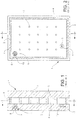
- FIGS. 1 and 2 illustrate a typical VIG unit 1 and elements that form the VIG unit 1.
- VIG unit 1 may include two spaced apart glass substrates 2, 3, which enclose an evacuated low-pressure space/cavity 6 therebetween. Glass sheets or substrates 2,3 are interconnected by a peripheral edge seal 4 which may be made of fused solder glass, for example.
- An array of support pillars/spacers 5 may be included between the glass substrates 2, 3 to maintain the spacing of substrates 2, 3 of the VIG unit 1 in view of the low-pressure space/gap present between the substrates 2, 3.
- a pump-out tube 8 may be hermetically sealed by, for example, solder glass 9 to an aperture/hole 10 that passes from an interior surface of one of the glass substrates 2 to the bottom of a recess 11 in the exterior surface of the glass substrate 2.
- a vacuum is attached to pump-out tube 8 to evacuate the interior cavity 6 to a low pressure, for example, using a sequential pump down operation. After evacuation of the cavity 6, the tube 8 is melted to seal the vacuum. Recess 11 retains the sealed pump-out tube 8.
- a chemical getter 12 may be included within a recess 13 that is disposed in an interior face of one of the glass substrates, e.g., glass substrate 2. The chemical getter 12 may be used to absorb or bind with certain residual impurities that may remain after the cavity 6 is evacuated and sealed.
- VIG units with fused solder glass peripheral edge seals 4 are typically manufactured by depositing glass frit, in a solution (e.g., frit paste), around the periphery of substrate 2. This glass frit paste ultimately forms the glass solder edge seal 4.
- a second substrate 3 is brought down on substrate 2 so as to sandwich spacers/pillars 5 and the glass frit solution between the two substrates 2, 3.
- the entire assembly including the glass substrates 2, 3, the spacers or pillars 5 and the seal material e.g., glass frit in solution or paste
- the seal material e.g., glass frit in solution or paste
- a vacuum is drawn via the pump-out tube 8 to form low pressure space/cavity 6 between the substrates 2, 3.
- the pressure in space 6 may be produced by way of an evacuation process to a level below atmospheric pressure, e.g., below about 10 -2 Torr.
- substrates 2, 3 are hermetically sealed. Small high strength spacers/pillars 5 are provided between the substrates to maintain separation of the approximately parallel substrates against atmospheric pressure.
- the pump-out tube 8 may be sealed, for example, by melting using a laser or the like.
- residual hydrocarbons and/or polymers such as, for example, solvents and binders used for making the frit paste that ultimately forms the seal between the transparent glass substrates of the VIG unit, may remain in the vacuum cavity. It is desirable to remove these residuals, as they have a potentially damaging effect on the VIG unit over time. For example, residual hydrocarbons and/or polymers may contaminate the vacuum cavity after the VIG is sealed (e.g., by producing volatile CO X gases that degrade vacuum levels), and thereby continuously degrade the insulating value (e.g., R-value) of the VIG unit.
- the residual hydrocarbons may also react with coatings, such as, for example, a low-E coating that may be present on an interior surface of one of the glass substrates that form the vacuum cavity, further damaging performance of the VIG unit.
- VIG units with fused solder glass edge seals 4 are typically manufactured by depositing glass frit, in a solution (e.g., frit paste), around the periphery of substrate 2. This glass frit ultimately forms the glass solder seal 4.
- a second substrate 3 is brought down on substrate 2 so as to sandwich spacers/pillars 5 and the glass frit solution between the two substrates 2, 3.
- the entire assembly including the glass substrates 2, 3, the spacers/pillars 5 and the seal material e.g., glass frit in solution
- An advantage of providing this high-temperature processing is that much of the residual hydrocarbon and/or polymer compounds, such as, for example, the binders and solvents used to make the frit paste for the solder glass seal 4, are oxidized or burned off during this process and are then removed from the vacuum cavity prior to sealing.
- a vanadium inclusive seal composition is disclosed in US 2012 21 39 54 A1 , entitled, "Coefficient of Thermal Expansion Filler for Vanadium-Based Frit Materials and/or Methods of Making and/or Using the Same," filed January 20, 2012.
- These new seal compositions may sometimes be referred to as VBZ (e.g., vanadium, barium, zinc) based compositions.
- VBZ e.g., vanadium, barium, zinc
- VBZ type seal compositions when using VBZ type seal compositions, a lower temperature sealing thermal profile is used to maintain the desired temper of the glass of the VIG unit because VBZ compositions have a lower firing temperature (e.g., ⁇ 250°C) than certain other conventional glass frit compositions used to form seals in VIG units.
- a lower firing temperature e.g., ⁇ 250°C
- certain other conventional glass frit compositions used to form seals in VIG units e.g., ⁇ 250°C
- VBZ seal compositions may begin to soften at the higher temperatures (e.g., 300°C-350°C). As a result of this softening, gases being evolved during the burning of residual carbon compounds become entrapped in the VBZ material.
- the lower thermal profile used to form a VBZ type seal is such that the normal high-temperature burn out procedure described above regarding fused solder glass seals 4 to oxidize and burn off residual hydrocarbons and polymers cannot be used.
- the lower seal curing temperature(s) used to cure/form the edge seal, when the seal is made of a vanadium inclusive and/or VBZ material, are insufficient to provide acceptable burn off of residual hydrocarbons and polymers.
- a lower temperature method to rapidly decompose the residual hydrocarbons and/or polymers in the cavity of the VIG unit in at least situations that use lower temperature profile edge seal compositions, such as, for example, and without limitation, vanadium based and/or VBZ type seal compositions.
- lower temperature profile edge seal compositions such as, for example, and without limitation, vanadium based and/or VBZ type seal compositions.
- a new lower temperature sealing thermal profile is generally used to maintain desired temper strength of the glass substrates of the VIG unit and/or to maintain the structural stability and vacuum maintaining properties of the resulting seal.
- the lower temperature cycle is not typically sufficient to sufficiently remove and/or burn off a sufficient amount of residual hydrocarbons and polymers, such as, for example, and without limitation, from the solvent and binder materials used for making the edge seal paste.
- the hydrocarbon and/or polymer residue in the interior of the VIG vacuum cavity may contaminate the vacuum once the VIG unit is sealed, and may further degrade various coatings that may be present on interior surfaces of the glass substrates used in the VIG units. For example, in certain instances residual carbon that coats the internal surface of the glass substrate(s) may remain, such as, for example, with a thin monolayer of hydrocarbons and binder polymer.
- This carbon residue may detach from the interior surface of the glass over time and decompose under ultraviolet radiation of sunlight and produce volatile, for example, CO X gases which degrade the vacuum levels and adversely decrease the insulating value (e.g., R-value) of the VIG unit. Additionally, the residual carbons may, over time, react with coatings on the interior glass surface, such as, for example, low-E coatings, further degrading performance of the VIG unit.
- volatile, for example, CO X gases which degrade the vacuum levels and adversely decrease the insulating value (e.g., R-value) of the VIG unit.
- the residual carbons may, over time, react with coatings on the interior glass surface, such as, for example, low-E coatings, further degrading performance of the VIG unit.
- a new cleaning process to remove residual hydrocarbon compounds is disclosed and described herein with reference to certain example embodiments.
- ozone (O 3 ) as a component of a purge gas used during initial pump down has been found to oxidize carbon compounds and convert them to more volatile CO and/or CO 2 that may then be easily removed through sequential pump down operations and may be even further diluted by optional sequential N 2 purging and a final deep vacuum pull down.
- the removal of these residual carbon compounds enhances the overall performance of VIG units by, for example, and without limitation, enhancing the overall insulating value (e.g., R-value), improving the useful life of the VIG unit and/or reducing degradation of optional coatings that may be used on an interior surface of the glass substrates of the VIG unit.
- enhancing the overall insulating value e.g., R-value
- an example method of decomposing residual carbon for removal from the vacuum cavity of a VIG window unit wherein at least an ozone (O 3 ) and oxygen (O 2 ) gas mixture is introduced into the VIG vacuum cavity during and/or before an initial stage of a vacuum pump down process.
- a small percentage of O 3 such as, for example, and without limitation, in a range of about from 5-10 wt.% ozone, is generated using, for example, an ozone generator using air and/or pure oxygen.
- the resulting O 3 /O 2 mixture is then introduced into the vacuum cavity of the VIG under reduced pressure, allowed to react with the residual hydrocarbons and/or polymers, and then removed from the cavity by, for example, a vacuum pump.
- a cycle of O 3 /O 2 purges may be repeated as necessary to reduce the contaminants to suitable or acceptable levels.
- Example acceptable contaminant levels may be, for example, and without limitation, from about 10E-12 or lower. It will be understood that acceptable contaminant levels may be determined or selected by the manufacturer.
- the ozonization of the vacuum cavity of the VIG unit described above is according to the invention performed at substantially ambient temperatures thereby avoiding the disadvantages and problems associated with high-temperature processing, especially for example when using newer seal compositions, such as, for example, vanadium inclusive and/or VBZ type seal compositions.
- additional energy may be used to facilitate and/or improve the carbon removal achieved by the ozonization process described above.
- additional energy in the form of, for example, and without limitation, radio frequency (RF) plasma, corona discharge (electric fields), UV lamp, and/or the like, may be used to increase reaction rates of the residual hydrocarbons and/or polymers and the ozone.
- the resulting trace amounts of volatile carbons that may remain, even after an ozonization process may be further diluted by sequential N 2 purging and/or a final deep vacuum pull down.
- an ozonization process along the lines described by way of example above, facilitates removal of residual carbon compounds, improves the overall lifetime of a VIG window unit, provides a more stable and predictable R-value and helps maintain coatings that may be present on the surface of the glass substrate in the vacuum cavity.
- an apparatus comprising: an ozone generator; a bi-directional pump operatively coupled to said ozone generator and operatively coupled to a pump-out tube, said pump-out tube providing access to a cavity between first and second substrates; and a gas source providing a gas including oxygen to the ozone generator, wherein said bi-directional pump pumping the cleaning gas mixture comprising ozone generated by the ozone generator into the cavity, maintaining the cleaning gas mixture comprising ozone in the cavity for a predetermined dwell time, and removing compounds created by reaction of the cleaning gas mixture and residual cleaning gas from the cavity
- a substantially ambient temperature cleaning process is provided to remove the residual hydrocarbon compounds that may be present in a vacuum cavity of a VIG window unit, in making vacuum IG window units.
- providing ozone (O 3 ) as a component of a purge gas used during initial pump down may be used to oxidize carbon compounds and convert them to more volatile compounds, such as, for example, and without limitation, CO or CO 2 , that may then be easily removed through sequential pump down and may be even further diluted by sequential N 2 purging and a final deep vacuum pull down.
- VIG window units by, for example, and without limitation, maintaining the overall insulating value (e.g., R-value), improving the useful life of the VIG window unit and reducing degradation of coatings that may be used on an interior surface of the glass substrates of the VIG unit.
- VIG window units may be used as windows in residential homes, office buildings, apartment buildings, doors, and/or the like.
- an example method of decomposing the residual carbon for removal from the cavity of a VIG window unit wherein an ozone (O 3 ) and oxygen (O 2 ) mixture, for example, is introduced into the VIG window unit cavity prior to or during an initial stage of a vacuum pump down process for evacuating the cavity.
- the example O 3 /O 2 mixture replaces at least some of the previously used nitrogen (N 2 ) purges performed to dilute trace gases in the VIG vacuum cavity.
- a small percentage of O 3 such as, for example, and without limitation, may preferably be in a range of about 1-15 wt.
- % ozone may be more preferably in a range of about 5-10 wt.% ozone, and may be even more preferably in a range of 7.5-8.0 wt. % ozone, with the remainder being primarily oxygen, is generated using, for example, an ozone generator using air or pure oxygen. Small amounts of other elements may be present in the ozone mixture used for ozonization according to certain example embodiments without affecting the desirable properties of the ozone mixture. Using higher ozone percentage may result in disadvantageous reactions between the ozone and coatings, such as, for example, low-E coatings, that may be provided on an interior surface of at least one of the transparent glass substrates of the VIG unit.
- O 3 /O 2 mixture is then introduced into the cavity of the VIG under reduced pressure, allowed to react with the residual hydrocarbons and/or polymers, and then removed from the cavity by, for example, a vacuum pump.
- a cycle of O 3 /O 2 purges may be repeated as necessary to reduce the contaminants to suitable or acceptable levels.
- a preferred number of O 3 /O 2 purge cycles may be in a range of about 1-15 cycles, or more preferably about 2-10 cycles, and even more preferably about 2-6 cycles.
- dwell times for the O 3 /O 2 purge cycles may be limited to reduce the possibility of undesirable reaction of ozone with, for example, coatings that may be provided on an interior surface of at least one glass substrate of the VIG window unit.
- preferred dwell times may be in a range of about 5-25 sec., or more preferably in a range of about 10-20 sec., and more preferably in a range of about 10-15 sec., and in any event, preferably less than 30-45 sec.
- the dwell time is the period of time that the cleaning gas mixture comprising ozone is maintained in the cavity.
- Example acceptable contaminant levels may be, for example, and without limitation, about 10E-12 or lower. It will be understood that acceptable contaminant levels may be determined or selected by the manufacturer.
- the ozonization of the cavity of the VIG window unit described above may be performed at substantially ambient temperatures thereby avoiding the disadvantages and problems associated with high-temperature processing, especially when using newer edge seal compositions, such as, for example, vanadium based or VBZ type edge seal compositions.
- ozonization is performed in a low temperature at about ambient temperatures. According to further example embodiments, it may be the case that additional energy may be required to facilitate or improve the carbon removal achieved by the ozonization process described above.
- RF radio frequency
- corona discharge electric fields
- UV lamp or the like
- resulting trace amounts of volatile carbons that may remain, even after an ozonization process such as, for example, those described above, may be further diluted by sequential N 2 purging and/or a final deep vacuum pull down.
- an ozonization process along the lines described by way of example above facilitates removal of residual carbon compounds, improves the overall lifetime of a VIG unit, provides a more stable R value and helps maintain coatings that may be present on the surface(s) of the glass substrates in the vacuum cavity.
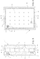
- the VIG window unit 1 includes spaced apart first and second transparent glass substrates 2, 3 that may be interconnected by an edge seal 15, which may, for example, be of or include a vanadium based or VBZ type seal 15.
- edge seal 15 may, for example, be of or include a vanadium based or VBZ type seal 15.
- Example vanadium based or VBZ type seal compositions are disclosed in US 2012 21 39 54 A1, filed January 20, 2012 . It will be understood that the embodiments disclosed herein are equally applicable to VIG configurations using any suitable seal material.
- the transparent glass substrates 2, 3 may be approximately the same size.
- one glass substrate may be larger than the other to provide, for example, an approximately L-shaped step proximate an edge of the VIG unit.
- One or both of the glass substrates 2, 3 may also optionally include at least one coating material (not shown), such as, for example, and without limitation, a low-E coating. It will be understood that various coatings may be present on an interior surface of at least one of the glass substrates 2, 3, and that such coatings provide various beneficial performance characteristics to the VIG unit 1.
- the VIG window unit has a visible transmission of at least about 30%, more preferably of at least about 40%, even more preferably of at least about 50%, and even more preferably of at least about 60% or 70%.
- an array of support pillars/spacers 5 may also be included between the glass substrates 2, 3 to maintain the spacing of the substrates in view of the lower than atmospheric pressure that is ultimately provided in cavity 6 between the substrates 2, 3.
- the spacers may have a height, for example, of about 0.1 to 1.0 mm, more preferably from about 0.2 to 0.4 mm. The height of the spacers may define the height of the vacuum cavity 6.
- the spacers 5 are preferably of a size that is sufficiently small so as to be visibly unobtrusive.
- the spacers may be made of or include solder glass, glass, ceramic, metal, polymer, or any other suitable material.
- the spacers 5 may be, for example, generally cylindrical, round, spherical, dime-shaped, C-shaped, pillow-shaped or any other suitable shape.
- a pump-out tube 8, that may be hermetically sealed, for example, using solder glass 9 is provided through a hole 10 that passes from an interior surface of one of the glass substrates, e.g., substrate 3 and through the glass substrate 3 and extending beyond the outside surface thereof.
- the pump-out tube 8 is used in a process to evacuate the cavity 6 between the substrates 2, 3, such as, for example, by attaching a vacuum pump to the pump-out tube 8 and evacuating the cavity to a low pressure, e.g., a pressure lower than atmospheric pressure.
- a pressure in the cavity 6 is, for example, preferably below about 10 -2 Torr, and more preferably below about 10 -3 Torr, and even more preferably below about 5x10 -4 Torr.
- the pump-out tube 8 may, for example, have a diameter or distance from about 0.1 to 1.0 mm, more preferably from about 0.3 to 0.7 mm, and even more preferably from about 0.5 mm.
- the pump-out tube 8 may be sealed, for example, by melting the tip of the tube 8 by any suitable means, such as, for example, by laser.
- FIG. 3 a schematic illustration of an example arrangement for providing ozonization of an example VIG window unit 1, such as, for example, illustrated in FIGS. 5 and 6 , according to certain example embodiments is shown.
- an ozone (O 3 ) and oxygen (O 2 ) mixture for example, is introduced into the vacuum cavity 6 of a VIG unit 1 during an initial stage of a vacuum pump down process.
- the peripheral edge seal 15 is preferably of or includes a vanadium based compound or VBZ, such as, for example, and without limitation, the edge seal compounds disclosed in US 2012 21 39 54 A1 .
- the VIG window unit may use any seal material.
- the example O 3 /O 2 mixture replaces at least some of the previously used nitrogen (N 2 ) purges performed to dilute trace gases in the VIG vacuum cavity.
- a small percentage of O 3 such as, for example, and without limitation, may preferably be in a range from about 1-15 wt. % ozone, may be more preferably in a range from about 5-10 wt.% ozone, and may be even more preferably in a range from about 7.5-8.0 wt.
- % ozone is generated using, for example, an ozone generator 25 using pure oxygen from an oxygen supply 20, such as, for example, and without limitation, a compressed oxygen tank.
- an ozone generator 25 may also generate the O 3 /O 2 mixture by processing air and that small amounts of other elements may be present in the mixture without adversely affecting the beneficial properties of the mixture.
- Using higher ozone percentages may result in disadvantageous reactions between the ozone and coatings, such as, for example, low-E coatings (not shown), that may be provided on an interior surface of at least one of the glass substrates 2, 3 of the VIG unit 1.
- the resulting O 3 /O 2 mixture is then introduced via pump 30 into the vacuum cavity 6 of the VIG 1 under reduced pressure.
- the vacuum pump 30 may preferably be connected to the vacuum cavity 6 of the VIG unit 1 via pump-out tube 8.
- the O 3 /O 2 mixture is then allowed to react with the residual hydrocarbons and/or polymers to oxidize residual carbon compounds, such as, for example, and without limitation, hydrocarbons and/or polymers, and convert them to more volatile CO or CO 2 that may then be easily removed through a subsequent sequential pump down.
- preferred dwell times for the O 3 /O 2 mixture in the cavity 6 may be in a range from about 5-25 sec., or more preferably in a range from about 10-20 sec., and even more preferably in a range from about 10-15 sec., and in any event, preferably less than 30-45 sec.
- the residual O 3 /O 2 mixture, together with reacted residual hydrocarbons and/or polymers, are then removed from the cavity 6 by, for example, vacuum pump 30.
- a cycle of O 3 /O 2 purges may be repeated as necessary to reduce the contaminants to suitable or acceptable levels.
- a preferred number of O 3 /O 2 purge cycles may be in a range from about 1-15 cycles, or more preferably in a range from about 2-10 cycles, and even more preferably in a range from about 2-6 cycles.
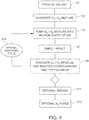
- FIG. 4 a flowchart illustrating a method for cleaning a vacuum cavity of a VIG window unit using a cycle of ozonization along the lines described above is provided.
- a VIG window unit having a sealed vacuum cavity with a completed seal of or including, for example, and without limitation, a vanadium based or VBZ compound, and an unsealed pump-out tube is provided S1.
- the pump-out tube is connected to a pump, preferably a bi-directional pump, that both forces gas(es) and/or gas mixtures into the vacuum cavity as well as evacuating gas(es) and/or gas mixtures and other volatile compound from the vacuum cavity.
- the pump may be connected to the vacuum cavity of the VIG unit to provide an ozone (O 3 ) and oxygen (O 2 ) mixture, for example, into the vacuum cavity of a VIG window unit during an initial stage of a vacuum pump down process.
- the seal is preferably of or includes a vanadium based compound or VBZ.
- a small percentage of O 3 such as, for example, and without limitation, may preferably be in a range from about 1-15 wt. % ozone, may be more preferably in a range from about 5-10 wt.% ozone, and may be even more preferably in a range from about 7.5-8.0 wt.
- % ozone is generated S3 as discussed above using, for example, an ozone generator using pure oxygen from an oxygen supply, such as, for example, and without limitation, a compressed oxygen tank.
- an ozone generator may also generate the O 3 /O 2 mixture by processing air and that small amounts of other elements may be present in the mixture without adversely affecting the beneficial properties of the mixture.
- Using higher ozone percentages may result in disadvantageous reactions between the ozone and coatings, such as, for example, low-E coatings (not shown), that may be provided on an interior surface of at least one of the glass substrates of the VIG window unit.
- the resulting O 3 /O 2 mixture is then introduced via pump into the vacuum cavity of the VIG, for example, under reduced pressure S5.
- the vacuum pump may preferably be connected to the vacuum cavity of the VIG unit via pump-out tube.
- the O 3 /O 2 mixture is then allowed to react with the residual hydrocarbons and/or polymers S7 to oxidize residual carbon compounds, such as, for example, and without limitation, hydrocarbons and/or polymers, and convert them to more volatile CO or CO 2 that may then be easily removed through a subsequent sequential pump down.
- preferred dwell times for the O 3 /O 2 mixture in the cavity S7 may be in a range from about 5-25 sec., or more preferably in a range from about 10-20 sec., and even more preferably in a range of about 10-15 sec., and in any event, preferably less than 30-45 sec.
- the residual O 3 /O 2 mixture, together with reacted residual hydrocarbons and/or polymers, are then removed from the cavity by, for example, vacuum pump S9.
- a cycle of O 3 /O 2 purges (s10 and S5, S7, S9) may be repeated as necessary to reduce the contaminants to suitable or acceptable levels.
- a preferred number of O 3 /O 2 purge cycles may be in a range of about 1-15 cycles, or more preferably in a range of about 2-10 cycles, and even more preferably in a range of about 2-6 cycles.
- additional energy may be required to facilitate or improve the carbon removal achieved by the ozonization process described above.
- additional energy in the form of, for example, and without limitation, elevated temperatures (remaining below levels that might adversely affect the edge seal composition), radio frequency (RF) plasma, corona discharge (electric fields), UV lamp, or the like, S11 may be used to increase reaction rates of the residual hydrocarbons and/or polymers and the ozone.
- RF radio frequency
- resulting trace amounts of volatile carbons that may remain, even after an ozonization process such as, for example, those described above, may be further diluted by sequential N 2 purging S13 and a final deep vacuum pull down.
- an ozonization process described by way of example above facilitates removal of residual carbon compounds, improves the overall lifetime of a VIG unit, provides a more stable R value and helps maintain coatings that may be present on the surface(s) of the glass substrates in the vacuum cavity.
- a method of making a vacuum insulated glass window unit comprising: providing first and second glass substrates for the vacuum insulated window unit, with a seal and a cavity located between the glass substrates; pumping a cleaning gas mixture comprising ozone into the cavity; and removing compounds created by reaction with the cleaning gas mixture, and residual cleaning gas, from the cavity.
- the method according to the invention further comprises maintaining at least part of the cleaning gas mixture comprising ozone in the cavity for a period of time.
- the period of time may be from about 10-15 seconds.
- the method may comprise providing additional energy during the step of maintaining by at least one of: (i) generating a radio frequency (RF) plasma proximate the cavity, (ii) generating a corona discharge proximate the cavity, and/or (iii) irradiating the substrates and the cavity with at least UV radiation.
- RF radio frequency
- said pumping, maintaining, and removing is performed at substantially ambient temperature.
- the method of any of the preceding two paragraphs may further comprise evacuating the cavity between the substrates to a pressure less than atmospheric pressure. Said pumping may be performed prior to, and/or during, said evacuating. After the evacuating, the method may include sealing a pump-out tube.
- the method of any of the preceding three paragraphs may comprise repeating at least the steps of pumping and removing at least two times, more preferably from two to six times.
- the method of any of the preceding four paragraphs may further comprise purging said cavity with gas comprising nitrogen.
- the purging may occur after at least a substantial portion of said cleaning gas mixture comprising ozone has been removed from the cavity.
- the method of any of the preceding five paragraphs may further comprise performing a deep vacuum purge of said cavity.
- said cleaning gas mixture comprises from about 1-15 wt. % ozone, more preferably from about 5-10 wt.% ozone.
- said cleaning gas mixture may further comprise oxygen.
- ozone of the cleaning gas mixture may react with residual hydrocarbons and/or polymers present in the cavity; and said removing may include removing compounds created by a reaction of ozone of the cleaning gas mixture and the residual hydrocarbons and/or polymers.
- the method of any of the preceding nine paragraphs may further comprise forming the seal so that the seal comprises vanadium.
- said seal may be an edge seal.
- the seal may comprise vanadium, barium and zinc.
Landscapes
- Engineering & Computer Science (AREA)
- Chemical & Material Sciences (AREA)
- Civil Engineering (AREA)
- Structural Engineering (AREA)
- General Chemical & Material Sciences (AREA)
- Chemical Kinetics & Catalysis (AREA)
- Life Sciences & Earth Sciences (AREA)
- Geochemistry & Mineralogy (AREA)
- Materials Engineering (AREA)
- Organic Chemistry (AREA)
- Joining Of Glass To Other Materials (AREA)
- Securing Of Glass Panes Or The Like (AREA)
- Cleaning In General (AREA)
- Physical Or Chemical Processes And Apparatus (AREA)
Claims (12)
- Ein Verfahren zum Herstellen einer Vakuum-Isolier-Fenstereinheit (1), wobei das Verfahren umfasst:Bereitstellen erster und zweiter Glassubstrate (2, 3) für die Vakuum-Isolier-Fenstereinheit (1) mit einer Abdichtung (15) und einem Hohlraum (6), welcher zwischen den Glassubstraten (2, 3) angeordnet ist;Pumpen eines Reinigungsgas-Gemisches, welches Ozon umfasst, in den Hohlraum;Beibehalten von zumindest einem Teil des Reinigungsgas-Gemisches, welches Ozon umfasst in dem Hohlraum (6) für eine Zeitspanne undEntfernen der Verbindungen, welche durch Reaktion mit dem Reinigungsgas-Gemisch erzeugt wurden und Resten von Reinigungsgas aus dem Hohlraum (6), wobeizumindest das Pumpen, Beibehalten und Entfernen bei im Wesentlichen Umgebungstemperatur durchgeführt werden.
- Verfahren nach Anspruch 1, wobei die Zeitspanne ungefähr 10 - 15 Sekunden beträgt.
- Verfahren nach irgendeinem der Ansprüche 1 oder 2, weiter umfassend ein Bereitstellen von zusätzlicher Energie, während des Schrittes des Beibehaltens, durch zumindest eines der Folgenden:(i) Erwärmen der Substrate (2,3) und des Hohlraums (6) dazwischen,(ii) Erzeugen eines Hochfrequenz-(RF) Plasmas in der Nähe des Hohlraums (6),(iii) Erzeugen einer Korona-Entladung in der Nähe des Hohlraums (6) und/oder(iv) Bestrahlen der Substrate und des Hohlraums (6) mit zumindest UV-Strahlung.
- Verfahren nach irgendeinem vorhergehenden Anspruch, weiter umfassend ein Evakuieren des Hohlraums (6) zwischen den Substraten (2,3) auf einen Druck, der geringer ist als ein atmosphärischer Druck, wobei das Pumpen vorzugsweise vor oder während des Evakuierens durchgeführt wird.
- Verfahren nach Anspruch 4, weiter umfassend ein Abdichten eines Abpump-Röhrchens (8) nach dem Evakuieren.
- Verfahren nach irgendeinem vorhergehenden Anspruch, weiter umfassend ein Wiederholen des Pumpens und Entfernens, zumindest zweimal und vorzugsweise zweibis sechs Mal.
- Verfahren nach irgendeinem vorhergehenden Anspruch, weiter umfassend ein Spülen des Hohlraums (6) mit Gas, welches Stickstoff umfasst, wobei das Spülen vorzugsweise stattfindet nachdem zumindest ein wesentlicher Teil des Reinigungsgas-Gemisches, welches Ozon umfasst, aus dem Hohlraum (6) entfernt wurde.
- Verfahren nach einem der Ansprüche 1 - 7, weiter umfassend ein Tief-Vakuumspülen des Hohlraums (6).
- Verfahren nach irgendeinem vorhergehenden Anspruch, wobei das Reinigungsgas-Gemisch ungefähr 1 - 15 Gew.-% und vorzugsweise ungefähr 5 - 10 Gew.-% Ozon umfasst.
- Verfahren nach einem vorhergehenden Anspruch, wobei das Reinigungsgas-Gemisch weiter Sauerstoff umfasst.
- Verfahren nach irgendeinem vorhergehenden Anspruch, wobei das Ozon des Reinigungsgas-Gemisches mit Rest-Kohlenwasserstoffen und/oder -Polymeren, welche in dem Hohlraum (6) vorhanden sind, reagiert; und
wobei das Entfernen das Entfernen von Bestandteilen beinhaltet, welche durch eine Reaktion des Ozons des Reinigungsgas-Gemisches und den Rest-Kohlenwasserstoffen und/oder -Polymeren erzeugt wurden. - Verfahren nach irgendeinem vorhergehenden Anspruch weiter umfassend ein Bilden der Abdichtung (15), so dass die Abdichtung (15) Vanadium und vorzugsweise Vanadium, Barium und Zink umfasst.
Priority Applications (1)
| Application Number | Priority Date | Filing Date | Title |
|---|---|---|---|
| PL13720209T PL2844816T3 (pl) | 2012-05-03 | 2013-04-26 | Sposób i aparat wykonywania jednostki okiennej szkła izolowanego próżniowo (vig), zawierającej wnękę oczyszczania |
Applications Claiming Priority (2)
| Application Number | Priority Date | Filing Date | Title |
|---|---|---|---|
| US13/463,262 US9169155B2 (en) | 2012-05-03 | 2012-05-03 | Method and apparatus for making vacuum insulated glass (VIG) window unit including cleaning cavity thereof |
| PCT/US2013/038333 WO2013165827A1 (en) | 2012-05-03 | 2013-04-26 | Method and apparatus for making vacuum insulated glass (vig) window unit including cleaning cavity thereof |
Publications (2)
| Publication Number | Publication Date |
|---|---|
| EP2844816A1 EP2844816A1 (de) | 2015-03-11 |
| EP2844816B1 true EP2844816B1 (de) | 2018-11-07 |
Family
ID=48237299
Family Applications (1)
| Application Number | Title | Priority Date | Filing Date |
|---|---|---|---|
| EP13720209.9A Active EP2844816B1 (de) | 2012-05-03 | 2013-04-26 | Verfahren und vorrichtung zur herstellung einer fenstereinheit aus vakuumisoliertem glas (vig) mit reinigungshohlraum |
Country Status (9)
| Country | Link |
|---|---|
| US (1) | US9169155B2 (de) |
| EP (1) | EP2844816B1 (de) |
| JP (1) | JP6452603B2 (de) |
| CN (1) | CN104411909B (de) |
| DK (1) | DK2844816T3 (de) |
| ES (1) | ES2707589T3 (de) |
| PL (1) | PL2844816T3 (de) |
| TR (1) | TR201901239T4 (de) |
| WO (1) | WO2013165827A1 (de) |
Families Citing this family (24)
| Publication number | Priority date | Publication date | Assignee | Title |
|---|---|---|---|---|
| US9290408B2 (en) | 2011-02-22 | 2016-03-22 | Guardian Industries Corp. | Vanadium-based frit materials, and/or methods of making the same |
| US9309146B2 (en) | 2011-02-22 | 2016-04-12 | Guardian Industries Corp. | Vanadium-based frit materials, binders, and/or solvents and methods of making the same |
| US8802203B2 (en) | 2011-02-22 | 2014-08-12 | Guardian Industries Corp. | Vanadium-based frit materials, and/or methods of making the same |
| US10012019B2 (en) | 2013-12-31 | 2018-07-03 | Guardian Glass, LLC | Vacuum insulating glass (VIG) unit with metallic peripheral edge seal and/or methods of making the same |
| US9784027B2 (en) | 2013-12-31 | 2017-10-10 | Guardian Glass, LLC | Vacuum insulating glass (VIG) unit with metallic peripheral edge seal and/or methods of making the same |
| US10280680B2 (en) | 2013-12-31 | 2019-05-07 | Guardian Glass, LLC | Vacuum insulating glass (VIG) unit with pump-out port sealed using metal solder seal, and/or method of making the same |
| US9593527B2 (en) | 2014-02-04 | 2017-03-14 | Guardian Industries Corp. | Vacuum insulating glass (VIG) unit with lead-free dual-frit edge seals and/or methods of making the same |
| US9988302B2 (en) | 2014-02-04 | 2018-06-05 | Guardian Glass, LLC | Frits for use in vacuum insulating glass (VIG) units, and/or associated methods |
| US10165870B2 (en) | 2014-02-11 | 2019-01-01 | Anthony, Inc. | Display case door assembly with vacuum panel |
| US9498072B2 (en) | 2014-02-11 | 2016-11-22 | Anthony, Inc. | Display case door assembly with tempered glass vacuum panel |
| CN104961359B (zh) * | 2015-06-12 | 2017-11-21 | 洛阳兰迪玻璃机器股份有限公司 | 一种真空玻璃的除气方法及装置 |
| CN104961358B (zh) * | 2015-06-12 | 2018-02-13 | 洛阳兰迪玻璃机器股份有限公司 | 一种真空玻璃的除气方法及装置 |
| KR102662193B1 (ko) | 2015-07-01 | 2024-05-02 | 가디언 글라스, 엘엘씨 | 금속성 주변 에지 실을 구비한 진공 단열 유리(vig) 유닛 및/또는 그 제조 방법 |
| US10145005B2 (en) | 2015-08-19 | 2018-12-04 | Guardian Glass, LLC | Techniques for low temperature direct graphene growth on glass |
| AT517835B1 (de) * | 2015-10-15 | 2017-05-15 | Markus Joachim Patrick | Verfahren zur Herstellung eines hochisolierenden Elements |
| CN105439476A (zh) * | 2015-12-28 | 2016-03-30 | 太仓耀华玻璃有限公司 | 一种真空玻璃高效除气装置及方法 |
| US9687087B1 (en) | 2016-06-16 | 2017-06-27 | Anthony, Inc. | Display case door assembly with vacuum panel and lighting features |
| EP3827152B1 (de) * | 2018-07-23 | 2022-12-14 | VKR Holding A/S | Voraktive sauerstoffmodifikation zur bildung einer randabdichtung für vakuumisolierte verglasungen |
| US11293551B2 (en) | 2018-09-30 | 2022-04-05 | ColdQuanta, Inc. | Break-seal system with breakable-membrane bridging rings |
| US20220235601A1 (en) * | 2019-07-15 | 2022-07-28 | Annette Johncock KRISKO | Manufacturing of vacuum insulated glazing unit |
| WO2021116174A1 (en) * | 2019-12-10 | 2021-06-17 | Vkr Holding A/S | Triple pane vacuum insulated glass unit |
| EP4577717B1 (de) | 2022-11-23 | 2025-09-17 | Luxwall, Inc. | Vakuumisolierte platte mit keramischen abstandshaltern |
| US12410654B2 (en) | 2022-11-23 | 2025-09-09 | LuxWall, Inc. | Vacuum insulated panel with passivation layer |
| US12467308B2 (en) | 2022-11-23 | 2025-11-11 | LuxWall, Inc. | Vacuum insulated panel with tellurium oxide and/or vanadium oxide inclusive seal |
Citations (2)
| Publication number | Priority date | Publication date | Assignee | Title |
|---|---|---|---|---|
| JP2002187745A (ja) * | 2000-12-21 | 2002-07-05 | Nippon Sheet Glass Co Ltd | ガラスパネルの製造方法 |
| WO2007058374A1 (en) * | 2005-11-17 | 2007-05-24 | Fujifilm Corporation | Hydrophilic member and process for producing the same |
Family Cites Families (25)
| Publication number | Priority date | Publication date | Assignee | Title |
|---|---|---|---|---|
| US4028135A (en) * | 1976-04-22 | 1977-06-07 | The United States Of America As Represented By The Secretary Of The Army | Method of cleaning surfaces by irradiation with ultraviolet light |
| US5657607A (en) | 1989-08-23 | 1997-08-19 | University Of Sydney | Thermally insulating glass panel and method of construction |
| KR100253882B1 (ko) | 1992-01-31 | 2000-04-15 | 앤더슨 데릭 제이. | 단열 유리패널에 대한 개량 |
| KR100250396B1 (ko) | 1993-06-30 | 2000-04-01 | 앤더슨 데릭 제이. | 진공 글레이징의 구조방법 |
| US7025831B1 (en) * | 1995-12-21 | 2006-04-11 | Fsi International, Inc. | Apparatus for surface conditioning |
| US5998305A (en) * | 1996-03-29 | 1999-12-07 | Praxair Technology, Inc. | Removal of carbon from substrate surfaces |
| US6231676B1 (en) * | 1998-01-27 | 2001-05-15 | Seagate Technology Llc | Cleaning process for disc drive components |
| JP2000233950A (ja) * | 1999-02-16 | 2000-08-29 | Nippon Sheet Glass Co Ltd | ガラスパネルのスペーサ配置方法およびガラスパネルの製造装置 |
| US6555835B1 (en) * | 1999-08-09 | 2003-04-29 | Samco International, Inc. | Ultraviolet-ozone oxidation system and method |
| US6541083B1 (en) | 2000-01-11 | 2003-04-01 | Guardian Industries Corp. | Vacuum IG unit with alkali silicate edge seal and/or spacers |
| US6701749B2 (en) | 2000-09-27 | 2004-03-09 | Guardian Industries Corp. | Vacuum IG window unit with edge seal at least partially diffused at temper and completed via microwave curing, and corresponding method of making the same |
| US6692600B2 (en) * | 2001-09-14 | 2004-02-17 | Guardian Industries Corp. | VIG evacuation with plasma excitation |
| JP4210979B2 (ja) * | 2002-07-11 | 2009-01-21 | ファーネス ニューバーグ インク | 石油ハイドロカ−ボンBTEX(ベンゼン、トルエン、エチルベンゼン、キシレン)を含む溶液を、オゾン、過酸化水素及び超音波(Sonication)によるキャビテ−ションを組み合わせる事により分解処理し、汚染のない環境に無害な状態に変換する方法。 |
| JP4299021B2 (ja) * | 2003-02-19 | 2009-07-22 | ヤマト電子株式会社 | 封着加工材及び封着加工用ペースト |
| JP2005231930A (ja) | 2004-02-18 | 2005-09-02 | Nippon Sheet Glass Co Ltd | ガラスパネルの製造方法、及びその製造方法により製造されたガラスパネル |
| GB2415774B (en) * | 2004-06-30 | 2007-06-13 | Alan Mole | Air decontamination device and method |
| US8282768B1 (en) * | 2005-04-26 | 2012-10-09 | Novellus Systems, Inc. | Purging of porogen from UV cure chamber |
| KR101580699B1 (ko) * | 2007-07-31 | 2015-12-28 | 코닝 인코포레이티드 | Duv 광학 소자의 수명을 확장하는 세정방법 |
| US8137494B2 (en) | 2007-12-14 | 2012-03-20 | Guardian Industries Corp. | Vacuum insulating glass unit with large pump-out port, and/or method of making the same |
| US8506738B2 (en) | 2007-12-17 | 2013-08-13 | Guardian Industries Corp. | Localized heating via an infrared heat source array of edge seals for a vacuum insulating glass unit, and/or unitized oven with infrared heat source array for accomplishing the same |
| US8169685B2 (en) * | 2007-12-20 | 2012-05-01 | Ravenbrick, Llc | Thermally switched absorptive window shutter |
| JP5287558B2 (ja) * | 2008-11-21 | 2013-09-11 | 株式会社明電舎 | 基板処理方法 |
| WO2010109903A1 (ja) * | 2009-03-27 | 2010-09-30 | 日立粉末冶金株式会社 | ガラス組成物およびそれを用いた被覆部材と封着部材 |
| US8202587B2 (en) | 2009-05-01 | 2012-06-19 | Guardian Industries Corp. | Edge profiles for vacuum insulated glass (VIG) units, and/or VIG unit including the same |
| US8802203B2 (en) | 2011-02-22 | 2014-08-12 | Guardian Industries Corp. | Vanadium-based frit materials, and/or methods of making the same |
-
2012
- 2012-05-03 US US13/463,262 patent/US9169155B2/en active Active
-
2013
- 2013-04-26 WO PCT/US2013/038333 patent/WO2013165827A1/en not_active Ceased
- 2013-04-26 TR TR2019/01239T patent/TR201901239T4/tr unknown
- 2013-04-26 EP EP13720209.9A patent/EP2844816B1/de active Active
- 2013-04-26 JP JP2015510342A patent/JP6452603B2/ja active Active
- 2013-04-26 CN CN201380035504.0A patent/CN104411909B/zh active Active
- 2013-04-26 PL PL13720209T patent/PL2844816T3/pl unknown
- 2013-04-26 DK DK13720209.9T patent/DK2844816T3/en active
- 2013-04-26 ES ES13720209T patent/ES2707589T3/es active Active
Patent Citations (2)
| Publication number | Priority date | Publication date | Assignee | Title |
|---|---|---|---|---|
| JP2002187745A (ja) * | 2000-12-21 | 2002-07-05 | Nippon Sheet Glass Co Ltd | ガラスパネルの製造方法 |
| WO2007058374A1 (en) * | 2005-11-17 | 2007-05-24 | Fujifilm Corporation | Hydrophilic member and process for producing the same |
Also Published As
| Publication number | Publication date |
|---|---|
| DK2844816T3 (en) | 2019-03-04 |
| ES2707589T3 (es) | 2019-04-04 |
| CN104411909B (zh) | 2018-01-26 |
| TR201901239T4 (tr) | 2019-02-21 |
| PL2844816T3 (pl) | 2019-02-28 |
| JP6452603B2 (ja) | 2019-01-16 |
| US20130292000A1 (en) | 2013-11-07 |
| WO2013165827A1 (en) | 2013-11-07 |
| JP2015523298A (ja) | 2015-08-13 |
| US9169155B2 (en) | 2015-10-27 |
| CN104411909A (zh) | 2015-03-11 |
| EP2844816A1 (de) | 2015-03-11 |
Similar Documents
| Publication | Publication Date | Title |
|---|---|---|
| EP2844816B1 (de) | Verfahren und vorrichtung zur herstellung einer fenstereinheit aus vakuumisoliertem glas (vig) mit reinigungshohlraum | |
| JP4295965B2 (ja) | 断熱パネルと断熱窓の製造方法、および断熱パネル | |
| US8833105B2 (en) | Method and apparatus for making vacuum insulated glass (VIG) window unit including pump-out tube sealing technique | |
| US10267085B2 (en) | Method and apparatus for making vacuum insulated glass (VIG) window unit including pump-out tube | |
| US10829984B2 (en) | Method and apparatus for making vacuum insulated glass (VIG) window unit including pump-out tube | |
| DK2855816T3 (en) | PROCEDURE FOR PREPARING A VACUUM-INSULATED GLASS (VIG) WINDOW UNIT WITH REDUCED SEAL HEIGHT VARIATION | |
| CN104662247A (zh) | 制备含有活性吸气剂的真空绝缘玻璃(vig)窗单元的方法 | |
| US8502450B2 (en) | Vacuum tube and vacuum tube manufacturing apparatus and method | |
| GB2484738A (en) | A sealant comprising a getter for a low pressure discharge lamp | |
| GB2424755A (en) | A low-pressure discharge lamp for a photoionisation detector | |
| KR20070032149A (ko) | 플라즈마 디스플레이 패널의 후공정 방법 | |
| JPH04253141A (ja) | 表示管 | |
| KR20080090748A (ko) | 플라즈마 디스플레이 패널의 제조방법 | |
| KR101425308B1 (ko) | 진공유리 또는 그를 이용하는 반도체 소자의 진공 봉지 방법 | |
| JP2006318740A (ja) | 保護膜安定化装置及びpdp製造装置 | |
| KR20010104469A (ko) | 게터물질이 도포된 플라즈마 디스플레이 패널 및 그제조방법 | |
| JP2005332673A (ja) | ディスプレイパネルの製造方法 | |
| JPH04255636A (ja) | 表示管 | |
| JPS6329371B2 (de) | ||
| KR20060126064A (ko) | 플라즈마 디스플레이 패널의 제조방법 | |
| JP2009266717A (ja) | プラズマディスプレイパネルの製造方法 |
Legal Events
| Date | Code | Title | Description |
|---|---|---|---|
| PUAI | Public reference made under article 153(3) epc to a published international application that has entered the european phase |
Free format text: ORIGINAL CODE: 0009012 |
|
| 17P | Request for examination filed |
Effective date: 20141202 |
|
| AK | Designated contracting states |
Kind code of ref document: A1 Designated state(s): AL AT BE BG CH CY CZ DE DK EE ES FI FR GB GR HR HU IE IS IT LI LT LU LV MC MK MT NL NO PL PT RO RS SE SI SK SM TR |
|
| AX | Request for extension of the european patent |
Extension state: BA ME |
|
| DAX | Request for extension of the european patent (deleted) | ||
| STAA | Information on the status of an ep patent application or granted ep patent |
Free format text: STATUS: EXAMINATION IS IN PROGRESS |
|
| 17Q | First examination report despatched |
Effective date: 20161214 |
|
| TPAC | Observations filed by third parties |
Free format text: ORIGINAL CODE: EPIDOSNTIPA |
|
| RAP1 | Party data changed (applicant data changed or rights of an application transferred) |
Owner name: GUARDIAN GLASS, LLC |
|
| GRAP | Despatch of communication of intention to grant a patent |
Free format text: ORIGINAL CODE: EPIDOSNIGR1 |
|
| STAA | Information on the status of an ep patent application or granted ep patent |
Free format text: STATUS: GRANT OF PATENT IS INTENDED |
|
| INTG | Intention to grant announced |
Effective date: 20180529 |
|
| GRAS | Grant fee paid |
Free format text: ORIGINAL CODE: EPIDOSNIGR3 |
|
| GRAA | (expected) grant |
Free format text: ORIGINAL CODE: 0009210 |
|
| STAA | Information on the status of an ep patent application or granted ep patent |
Free format text: STATUS: THE PATENT HAS BEEN GRANTED |
|
| AK | Designated contracting states |
Kind code of ref document: B1 Designated state(s): AL AT BE BG CH CY CZ DE DK EE ES FI FR GB GR HR HU IE IS IT LI LT LU LV MC MK MT NL NO PL PT RO RS SE SI SK SM TR |
|
| REG | Reference to a national code |
Ref country code: GB Ref legal event code: FG4D |
|
| REG | Reference to a national code |
Ref country code: CH Ref legal event code: EP Ref country code: AT Ref legal event code: REF Ref document number: 1062250 Country of ref document: AT Kind code of ref document: T Effective date: 20181115 |
|
| REG | Reference to a national code |
Ref country code: IE Ref legal event code: FG4D |
|
| REG | Reference to a national code |
Ref country code: DE Ref legal event code: R096 Ref document number: 602013046273 Country of ref document: DE |
|
| REG | Reference to a national code |
Ref country code: DK Ref legal event code: T3 Effective date: 20190225 |
|
| REG | Reference to a national code |
Ref country code: NL Ref legal event code: MP Effective date: 20181107 |
|
| REG | Reference to a national code |
Ref country code: LT Ref legal event code: MG4D |
|
| REG | Reference to a national code |
Ref country code: ES Ref legal event code: FG2A Ref document number: 2707589 Country of ref document: ES Kind code of ref document: T3 Effective date: 20190404 |
|
| REG | Reference to a national code |
Ref country code: AT Ref legal event code: MK05 Ref document number: 1062250 Country of ref document: AT Kind code of ref document: T Effective date: 20181107 |
|
| PG25 | Lapsed in a contracting state [announced via postgrant information from national office to epo] |
Ref country code: AT Free format text: LAPSE BECAUSE OF FAILURE TO SUBMIT A TRANSLATION OF THE DESCRIPTION OR TO PAY THE FEE WITHIN THE PRESCRIBED TIME-LIMIT Effective date: 20181107 Ref country code: NO Free format text: LAPSE BECAUSE OF FAILURE TO SUBMIT A TRANSLATION OF THE DESCRIPTION OR TO PAY THE FEE WITHIN THE PRESCRIBED TIME-LIMIT Effective date: 20190207 Ref country code: LV Free format text: LAPSE BECAUSE OF FAILURE TO SUBMIT A TRANSLATION OF THE DESCRIPTION OR TO PAY THE FEE WITHIN THE PRESCRIBED TIME-LIMIT Effective date: 20181107 Ref country code: FI Free format text: LAPSE BECAUSE OF FAILURE TO SUBMIT A TRANSLATION OF THE DESCRIPTION OR TO PAY THE FEE WITHIN THE PRESCRIBED TIME-LIMIT Effective date: 20181107 Ref country code: IS Free format text: LAPSE BECAUSE OF FAILURE TO SUBMIT A TRANSLATION OF THE DESCRIPTION OR TO PAY THE FEE WITHIN THE PRESCRIBED TIME-LIMIT Effective date: 20190307 Ref country code: LT Free format text: LAPSE BECAUSE OF FAILURE TO SUBMIT A TRANSLATION OF THE DESCRIPTION OR TO PAY THE FEE WITHIN THE PRESCRIBED TIME-LIMIT Effective date: 20181107 Ref country code: HR Free format text: LAPSE BECAUSE OF FAILURE TO SUBMIT A TRANSLATION OF THE DESCRIPTION OR TO PAY THE FEE WITHIN THE PRESCRIBED TIME-LIMIT Effective date: 20181107 Ref country code: BG Free format text: LAPSE BECAUSE OF FAILURE TO SUBMIT A TRANSLATION OF THE DESCRIPTION OR TO PAY THE FEE WITHIN THE PRESCRIBED TIME-LIMIT Effective date: 20190207 |
|
| PG25 | Lapsed in a contracting state [announced via postgrant information from national office to epo] |
Ref country code: GR Free format text: LAPSE BECAUSE OF FAILURE TO SUBMIT A TRANSLATION OF THE DESCRIPTION OR TO PAY THE FEE WITHIN THE PRESCRIBED TIME-LIMIT Effective date: 20190208 Ref country code: NL Free format text: LAPSE BECAUSE OF FAILURE TO SUBMIT A TRANSLATION OF THE DESCRIPTION OR TO PAY THE FEE WITHIN THE PRESCRIBED TIME-LIMIT Effective date: 20181107 Ref country code: PT Free format text: LAPSE BECAUSE OF FAILURE TO SUBMIT A TRANSLATION OF THE DESCRIPTION OR TO PAY THE FEE WITHIN THE PRESCRIBED TIME-LIMIT Effective date: 20190307 Ref country code: AL Free format text: LAPSE BECAUSE OF FAILURE TO SUBMIT A TRANSLATION OF THE DESCRIPTION OR TO PAY THE FEE WITHIN THE PRESCRIBED TIME-LIMIT Effective date: 20181107 Ref country code: SE Free format text: LAPSE BECAUSE OF FAILURE TO SUBMIT A TRANSLATION OF THE DESCRIPTION OR TO PAY THE FEE WITHIN THE PRESCRIBED TIME-LIMIT Effective date: 20181107 Ref country code: RS Free format text: LAPSE BECAUSE OF FAILURE TO SUBMIT A TRANSLATION OF THE DESCRIPTION OR TO PAY THE FEE WITHIN THE PRESCRIBED TIME-LIMIT Effective date: 20181107 |
|
| PG25 | Lapsed in a contracting state [announced via postgrant information from national office to epo] |
Ref country code: CZ Free format text: LAPSE BECAUSE OF FAILURE TO SUBMIT A TRANSLATION OF THE DESCRIPTION OR TO PAY THE FEE WITHIN THE PRESCRIBED TIME-LIMIT Effective date: 20181107 |
|
| PGFP | Annual fee paid to national office [announced via postgrant information from national office to epo] |
Ref country code: AT Payment date: 20190503 Year of fee payment: 8 |
|
| REG | Reference to a national code |
Ref country code: DE Ref legal event code: R097 Ref document number: 602013046273 Country of ref document: DE |
|
| PG25 | Lapsed in a contracting state [announced via postgrant information from national office to epo] |
Ref country code: SK Free format text: LAPSE BECAUSE OF FAILURE TO SUBMIT A TRANSLATION OF THE DESCRIPTION OR TO PAY THE FEE WITHIN THE PRESCRIBED TIME-LIMIT Effective date: 20181107 Ref country code: RO Free format text: LAPSE BECAUSE OF FAILURE TO SUBMIT A TRANSLATION OF THE DESCRIPTION OR TO PAY THE FEE WITHIN THE PRESCRIBED TIME-LIMIT Effective date: 20181107 Ref country code: SM Free format text: LAPSE BECAUSE OF FAILURE TO SUBMIT A TRANSLATION OF THE DESCRIPTION OR TO PAY THE FEE WITHIN THE PRESCRIBED TIME-LIMIT Effective date: 20181107 Ref country code: EE Free format text: LAPSE BECAUSE OF FAILURE TO SUBMIT A TRANSLATION OF THE DESCRIPTION OR TO PAY THE FEE WITHIN THE PRESCRIBED TIME-LIMIT Effective date: 20181107 |
|
| PGFP | Annual fee paid to national office [announced via postgrant information from national office to epo] |
Ref country code: TR Payment date: 20190410 Year of fee payment: 7 |
|
| PLBE | No opposition filed within time limit |
Free format text: ORIGINAL CODE: 0009261 |
|
| STAA | Information on the status of an ep patent application or granted ep patent |
Free format text: STATUS: NO OPPOSITION FILED WITHIN TIME LIMIT |
|
| 26N | No opposition filed |
Effective date: 20190808 |
|
| PG25 | Lapsed in a contracting state [announced via postgrant information from national office to epo] |
Ref country code: SI Free format text: LAPSE BECAUSE OF FAILURE TO SUBMIT A TRANSLATION OF THE DESCRIPTION OR TO PAY THE FEE WITHIN THE PRESCRIBED TIME-LIMIT Effective date: 20181107 |
|
| REG | Reference to a national code |
Ref country code: CH Ref legal event code: PL |
|
| REG | Reference to a national code |
Ref country code: BE Ref legal event code: MM Effective date: 20190430 |
|
| PG25 | Lapsed in a contracting state [announced via postgrant information from national office to epo] |
Ref country code: MC Free format text: LAPSE BECAUSE OF FAILURE TO SUBMIT A TRANSLATION OF THE DESCRIPTION OR TO PAY THE FEE WITHIN THE PRESCRIBED TIME-LIMIT Effective date: 20181107 Ref country code: LU Free format text: LAPSE BECAUSE OF NON-PAYMENT OF DUE FEES Effective date: 20190426 |
|
| PG25 | Lapsed in a contracting state [announced via postgrant information from national office to epo] |
Ref country code: LI Free format text: LAPSE BECAUSE OF NON-PAYMENT OF DUE FEES Effective date: 20190430 Ref country code: CH Free format text: LAPSE BECAUSE OF NON-PAYMENT OF DUE FEES Effective date: 20190430 |
|
| PG25 | Lapsed in a contracting state [announced via postgrant information from national office to epo] |
Ref country code: BE Free format text: LAPSE BECAUSE OF NON-PAYMENT OF DUE FEES Effective date: 20190430 |
|
| PG25 | Lapsed in a contracting state [announced via postgrant information from national office to epo] |
Ref country code: IE Free format text: LAPSE BECAUSE OF NON-PAYMENT OF DUE FEES Effective date: 20190426 |
|
| PG25 | Lapsed in a contracting state [announced via postgrant information from national office to epo] |
Ref country code: CY Free format text: LAPSE BECAUSE OF FAILURE TO SUBMIT A TRANSLATION OF THE DESCRIPTION OR TO PAY THE FEE WITHIN THE PRESCRIBED TIME-LIMIT Effective date: 20181107 |
|
| PG25 | Lapsed in a contracting state [announced via postgrant information from national office to epo] |
Ref country code: MT Free format text: LAPSE BECAUSE OF FAILURE TO SUBMIT A TRANSLATION OF THE DESCRIPTION OR TO PAY THE FEE WITHIN THE PRESCRIBED TIME-LIMIT Effective date: 20181107 Ref country code: HU Free format text: LAPSE BECAUSE OF FAILURE TO SUBMIT A TRANSLATION OF THE DESCRIPTION OR TO PAY THE FEE WITHIN THE PRESCRIBED TIME-LIMIT; INVALID AB INITIO Effective date: 20130426 |
|
| REG | Reference to a national code |
Ref country code: ES Ref legal event code: FD2A Effective date: 20210906 |
|
| PG25 | Lapsed in a contracting state [announced via postgrant information from national office to epo] |
Ref country code: ES Free format text: LAPSE BECAUSE OF NON-PAYMENT OF DUE FEES Effective date: 20200427 |
|
| PG25 | Lapsed in a contracting state [announced via postgrant information from national office to epo] |
Ref country code: TR Free format text: LAPSE BECAUSE OF NON-PAYMENT OF DUE FEES Effective date: 20200426 Ref country code: MK Free format text: LAPSE BECAUSE OF FAILURE TO SUBMIT A TRANSLATION OF THE DESCRIPTION OR TO PAY THE FEE WITHIN THE PRESCRIBED TIME-LIMIT Effective date: 20181107 |
|
| PGFP | Annual fee paid to national office [announced via postgrant information from national office to epo] |
Ref country code: PL Payment date: 20250314 Year of fee payment: 13 |
|
| PGFP | Annual fee paid to national office [announced via postgrant information from national office to epo] |
Ref country code: DE Payment date: 20250305 Year of fee payment: 13 |
|
| PGFP | Annual fee paid to national office [announced via postgrant information from national office to epo] |
Ref country code: GB Payment date: 20260319 Year of fee payment: 14 |
|
| PGFP | Annual fee paid to national office [announced via postgrant information from national office to epo] |
Ref country code: DK Payment date: 20260323 Year of fee payment: 14 |
|
| PGFP | Annual fee paid to national office [announced via postgrant information from national office to epo] |
Ref country code: IT Payment date: 20260319 Year of fee payment: 14 |
|
| PGFP | Annual fee paid to national office [announced via postgrant information from national office to epo] |
Ref country code: FR Payment date: 20260320 Year of fee payment: 14 |