EP2844784B1 - Vorrichtung und verfahren zur oberflächenbehandlung eines substrats und verfahren zum herstellen eines optoelektronischen bauelements - Google Patents
Vorrichtung und verfahren zur oberflächenbehandlung eines substrats und verfahren zum herstellen eines optoelektronischen bauelements Download PDFInfo
- Publication number
- EP2844784B1 EP2844784B1 EP13719098.9A EP13719098A EP2844784B1 EP 2844784 B1 EP2844784 B1 EP 2844784B1 EP 13719098 A EP13719098 A EP 13719098A EP 2844784 B1 EP2844784 B1 EP 2844784B1
- Authority
- EP
- European Patent Office
- Prior art keywords
- gas
- substrate
- processing head
- head
- outer edge
- Prior art date
- Legal status (The legal status is an assumption and is not a legal conclusion. Google has not performed a legal analysis and makes no representation as to the accuracy of the status listed.)
- Active
Links
Images


Classifications
-
- C—CHEMISTRY; METALLURGY
- C23—COATING METALLIC MATERIAL; COATING MATERIAL WITH METALLIC MATERIAL; CHEMICAL SURFACE TREATMENT; DIFFUSION TREATMENT OF METALLIC MATERIAL; COATING BY VACUUM EVAPORATION, BY SPUTTERING, BY ION IMPLANTATION OR BY CHEMICAL VAPOUR DEPOSITION, IN GENERAL; INHIBITING CORROSION OF METALLIC MATERIAL OR INCRUSTATION IN GENERAL
- C23C—COATING METALLIC MATERIAL; COATING MATERIAL WITH METALLIC MATERIAL; SURFACE TREATMENT OF METALLIC MATERIAL BY DIFFUSION INTO THE SURFACE, BY CHEMICAL CONVERSION OR SUBSTITUTION; COATING BY VACUUM EVAPORATION, BY SPUTTERING, BY ION IMPLANTATION OR BY CHEMICAL VAPOUR DEPOSITION, IN GENERAL
- C23C16/00—Chemical coating by decomposition of gaseous compounds, without leaving reaction products of surface material in the coating, i.e. chemical vapour deposition [CVD] processes
- C23C16/44—Chemical coating by decomposition of gaseous compounds, without leaving reaction products of surface material in the coating, i.e. chemical vapour deposition [CVD] processes characterised by the method of coating
- C23C16/455—Chemical coating by decomposition of gaseous compounds, without leaving reaction products of surface material in the coating, i.e. chemical vapour deposition [CVD] processes characterised by the method of coating characterised by the method used for introducing gases into reaction chamber or for modifying gas flows in reaction chamber
- C23C16/45523—Pulsed gas flow or change of composition over time
- C23C16/45525—Atomic layer deposition [ALD]
-
- C—CHEMISTRY; METALLURGY
- C23—COATING METALLIC MATERIAL; COATING MATERIAL WITH METALLIC MATERIAL; CHEMICAL SURFACE TREATMENT; DIFFUSION TREATMENT OF METALLIC MATERIAL; COATING BY VACUUM EVAPORATION, BY SPUTTERING, BY ION IMPLANTATION OR BY CHEMICAL VAPOUR DEPOSITION, IN GENERAL; INHIBITING CORROSION OF METALLIC MATERIAL OR INCRUSTATION IN GENERAL
- C23C—COATING METALLIC MATERIAL; COATING MATERIAL WITH METALLIC MATERIAL; SURFACE TREATMENT OF METALLIC MATERIAL BY DIFFUSION INTO THE SURFACE, BY CHEMICAL CONVERSION OR SUBSTITUTION; COATING BY VACUUM EVAPORATION, BY SPUTTERING, BY ION IMPLANTATION OR BY CHEMICAL VAPOUR DEPOSITION, IN GENERAL
- C23C16/00—Chemical coating by decomposition of gaseous compounds, without leaving reaction products of surface material in the coating, i.e. chemical vapour deposition [CVD] processes
- C23C16/22—Chemical coating by decomposition of gaseous compounds, without leaving reaction products of surface material in the coating, i.e. chemical vapour deposition [CVD] processes characterised by the deposition of inorganic material, other than metallic material
- C23C16/30—Deposition of compounds, mixtures or solid solutions, e.g. borides, carbides, nitrides
- C23C16/40—Oxides
- C23C16/407—Oxides of zinc, germanium, cadmium, indium, tin, thallium or bismuth
-
- C—CHEMISTRY; METALLURGY
- C23—COATING METALLIC MATERIAL; COATING MATERIAL WITH METALLIC MATERIAL; CHEMICAL SURFACE TREATMENT; DIFFUSION TREATMENT OF METALLIC MATERIAL; COATING BY VACUUM EVAPORATION, BY SPUTTERING, BY ION IMPLANTATION OR BY CHEMICAL VAPOUR DEPOSITION, IN GENERAL; INHIBITING CORROSION OF METALLIC MATERIAL OR INCRUSTATION IN GENERAL
- C23C—COATING METALLIC MATERIAL; COATING MATERIAL WITH METALLIC MATERIAL; SURFACE TREATMENT OF METALLIC MATERIAL BY DIFFUSION INTO THE SURFACE, BY CHEMICAL CONVERSION OR SUBSTITUTION; COATING BY VACUUM EVAPORATION, BY SPUTTERING, BY ION IMPLANTATION OR BY CHEMICAL VAPOUR DEPOSITION, IN GENERAL
- C23C16/00—Chemical coating by decomposition of gaseous compounds, without leaving reaction products of surface material in the coating, i.e. chemical vapour deposition [CVD] processes
- C23C16/44—Chemical coating by decomposition of gaseous compounds, without leaving reaction products of surface material in the coating, i.e. chemical vapour deposition [CVD] processes characterised by the method of coating
- C23C16/455—Chemical coating by decomposition of gaseous compounds, without leaving reaction products of surface material in the coating, i.e. chemical vapour deposition [CVD] processes characterised by the method of coating characterised by the method used for introducing gases into reaction chamber or for modifying gas flows in reaction chamber
- C23C16/45523—Pulsed gas flow or change of composition over time
- C23C16/45525—Atomic layer deposition [ALD]
- C23C16/45544—Atomic layer deposition [ALD] characterized by the apparatus
- C23C16/45548—Atomic layer deposition [ALD] characterized by the apparatus having arrangements for gas injection at different locations of the reactor for each ALD half-reaction
- C23C16/45551—Atomic layer deposition [ALD] characterized by the apparatus having arrangements for gas injection at different locations of the reactor for each ALD half-reaction for relative movement of the substrate and the gas injectors or half-reaction reactor compartments
-
- C—CHEMISTRY; METALLURGY
- C23—COATING METALLIC MATERIAL; COATING MATERIAL WITH METALLIC MATERIAL; CHEMICAL SURFACE TREATMENT; DIFFUSION TREATMENT OF METALLIC MATERIAL; COATING BY VACUUM EVAPORATION, BY SPUTTERING, BY ION IMPLANTATION OR BY CHEMICAL VAPOUR DEPOSITION, IN GENERAL; INHIBITING CORROSION OF METALLIC MATERIAL OR INCRUSTATION IN GENERAL
- C23C—COATING METALLIC MATERIAL; COATING MATERIAL WITH METALLIC MATERIAL; SURFACE TREATMENT OF METALLIC MATERIAL BY DIFFUSION INTO THE SURFACE, BY CHEMICAL CONVERSION OR SUBSTITUTION; COATING BY VACUUM EVAPORATION, BY SPUTTERING, BY ION IMPLANTATION OR BY CHEMICAL VAPOUR DEPOSITION, IN GENERAL
- C23C16/00—Chemical coating by decomposition of gaseous compounds, without leaving reaction products of surface material in the coating, i.e. chemical vapour deposition [CVD] processes
- C23C16/44—Chemical coating by decomposition of gaseous compounds, without leaving reaction products of surface material in the coating, i.e. chemical vapour deposition [CVD] processes characterised by the method of coating
- C23C16/54—Apparatus specially adapted for continuous coating
- C23C16/545—Apparatus specially adapted for continuous coating for coating elongated substrates
-
- H—ELECTRICITY
- H10—SEMICONDUCTOR DEVICES; ELECTRIC SOLID-STATE DEVICES NOT OTHERWISE PROVIDED FOR
- H10K—ORGANIC ELECTRIC SOLID-STATE DEVICES
- H10K30/00—Organic devices sensitive to infrared radiation, light, electromagnetic radiation of shorter wavelength or corpuscular radiation
- H10K30/80—Constructional details
- H10K30/81—Electrodes
-
- H—ELECTRICITY
- H10—SEMICONDUCTOR DEVICES; ELECTRIC SOLID-STATE DEVICES NOT OTHERWISE PROVIDED FOR
- H10K—ORGANIC ELECTRIC SOLID-STATE DEVICES
- H10K30/00—Organic devices sensitive to infrared radiation, light, electromagnetic radiation of shorter wavelength or corpuscular radiation
- H10K30/80—Constructional details
- H10K30/88—Passivation; Containers; Encapsulations
-
- H—ELECTRICITY
- H10—SEMICONDUCTOR DEVICES; ELECTRIC SOLID-STATE DEVICES NOT OTHERWISE PROVIDED FOR
- H10K—ORGANIC ELECTRIC SOLID-STATE DEVICES
- H10K50/00—Organic light-emitting devices
- H10K50/80—Constructional details
- H10K50/84—Passivation; Containers; Encapsulations
-
- H—ELECTRICITY
- H10—SEMICONDUCTOR DEVICES; ELECTRIC SOLID-STATE DEVICES NOT OTHERWISE PROVIDED FOR
- H10K—ORGANIC ELECTRIC SOLID-STATE DEVICES
- H10K71/00—Manufacture or treatment specially adapted for the organic devices covered by this subclass
- H10K71/10—Deposition of organic active material
-
- H—ELECTRICITY
- H10—SEMICONDUCTOR DEVICES; ELECTRIC SOLID-STATE DEVICES NOT OTHERWISE PROVIDED FOR
- H10K—ORGANIC ELECTRIC SOLID-STATE DEVICES
- H10K71/00—Manufacture or treatment specially adapted for the organic devices covered by this subclass
- H10K71/60—Forming conductive regions or layers, e.g. electrodes
-
- H—ELECTRICITY
- H01—ELECTRIC ELEMENTS
- H01L—SEMICONDUCTOR DEVICES NOT COVERED BY CLASS H10
- H01L21/00—Processes or apparatus adapted for the manufacture or treatment of semiconductor or solid state devices or of parts thereof
- H01L21/02—Manufacture or treatment of semiconductor devices or of parts thereof
- H01L21/02104—Forming layers
- H01L21/02365—Forming inorganic semiconducting materials on a substrate
- H01L21/02518—Deposited layers
- H01L21/02521—Materials
- H01L21/02565—Oxide semiconducting materials not being Group 12/16 materials, e.g. ternary compounds
-
- H—ELECTRICITY
- H01—ELECTRIC ELEMENTS
- H01L—SEMICONDUCTOR DEVICES NOT COVERED BY CLASS H10
- H01L21/00—Processes or apparatus adapted for the manufacture or treatment of semiconductor or solid state devices or of parts thereof
- H01L21/02—Manufacture or treatment of semiconductor devices or of parts thereof
- H01L21/02104—Forming layers
- H01L21/02365—Forming inorganic semiconducting materials on a substrate
- H01L21/02612—Formation types
- H01L21/02617—Deposition types
- H01L21/0262—Reduction or decomposition of gaseous compounds, e.g. CVD
-
- H—ELECTRICITY
- H01—ELECTRIC ELEMENTS
- H01L—SEMICONDUCTOR DEVICES NOT COVERED BY CLASS H10
- H01L2224/00—Indexing scheme for arrangements for connecting or disconnecting semiconductor or solid-state bodies and methods related thereto as covered by H01L24/00
- H01L2224/01—Means for bonding being attached to, or being formed on, the surface to be connected, e.g. chip-to-package, die-attach, "first-level" interconnects; Manufacturing methods related thereto
- H01L2224/10—Bump connectors; Manufacturing methods related thereto
- H01L2224/15—Structure, shape, material or disposition of the bump connectors after the connecting process
- H01L2224/16—Structure, shape, material or disposition of the bump connectors after the connecting process of an individual bump connector
-
- H—ELECTRICITY
- H01—ELECTRIC ELEMENTS
- H01L—SEMICONDUCTOR DEVICES NOT COVERED BY CLASS H10
- H01L2924/00—Indexing scheme for arrangements or methods for connecting or disconnecting semiconductor or solid-state bodies as covered by H01L24/00
- H01L2924/10—Details of semiconductor or other solid state devices to be connected
- H01L2924/11—Device type
- H01L2924/12—Passive devices, e.g. 2 terminal devices
- H01L2924/1204—Optical Diode
- H01L2924/12044—OLED
-
- H—ELECTRICITY
- H10—SEMICONDUCTOR DEVICES; ELECTRIC SOLID-STATE DEVICES NOT OTHERWISE PROVIDED FOR
- H10K—ORGANIC ELECTRIC SOLID-STATE DEVICES
- H10K77/00—Constructional details of devices covered by this subclass and not covered by groups H10K10/80, H10K30/80, H10K50/80 or H10K59/80
- H10K77/10—Substrates, e.g. flexible substrates
-
- Y—GENERAL TAGGING OF NEW TECHNOLOGICAL DEVELOPMENTS; GENERAL TAGGING OF CROSS-SECTIONAL TECHNOLOGIES SPANNING OVER SEVERAL SECTIONS OF THE IPC; TECHNICAL SUBJECTS COVERED BY FORMER USPC CROSS-REFERENCE ART COLLECTIONS [XRACs] AND DIGESTS
- Y02—TECHNOLOGIES OR APPLICATIONS FOR MITIGATION OR ADAPTATION AGAINST CLIMATE CHANGE
- Y02E—REDUCTION OF GREENHOUSE GAS [GHG] EMISSIONS, RELATED TO ENERGY GENERATION, TRANSMISSION OR DISTRIBUTION
- Y02E10/00—Energy generation through renewable energy sources
- Y02E10/50—Photovoltaic [PV] energy
- Y02E10/549—Organic PV cells
-
- Y—GENERAL TAGGING OF NEW TECHNOLOGICAL DEVELOPMENTS; GENERAL TAGGING OF CROSS-SECTIONAL TECHNOLOGIES SPANNING OVER SEVERAL SECTIONS OF THE IPC; TECHNICAL SUBJECTS COVERED BY FORMER USPC CROSS-REFERENCE ART COLLECTIONS [XRACs] AND DIGESTS
- Y02—TECHNOLOGIES OR APPLICATIONS FOR MITIGATION OR ADAPTATION AGAINST CLIMATE CHANGE
- Y02P—CLIMATE CHANGE MITIGATION TECHNOLOGIES IN THE PRODUCTION OR PROCESSING OF GOODS
- Y02P70/00—Climate change mitigation technologies in the production process for final industrial or consumer products
- Y02P70/50—Manufacturing or production processes characterised by the final manufactured product
Definitions
- the invention relates to a device and a method for the surface treatment of a substrate and a method for producing an optoelectronic component.
- optoelectronic components with organic functional layers often have encapsulation layers below and/or above the organic functional layers, which protect the organic functional layers, for example from moisture.
- the encapsulation layers are applied, for example, by means of deposition methods, for example by means of atomic layer deposition or chemical vapor deposition.
- optoelectronic components for example light-absorbing or light-emitting cells such as electrochemical cells and OLEDs, but also organic solar cells. With all of these systems, the service life and performance depend to a large extent on the quality of the encapsulation.
- the substrate can be coated with different layers, for example the organically functional layers and/or the encapsulation layers.
- These layers can have only a few atomic layers or up to to be a few hundred nanometers thick.
- the layers can be applied, for example, using CVD (Chemical Vapor Deposition) methods or ALD (Atomic Layer Deposition) methods.
- CVD Chemical Vapor Deposition
- ALD Atomic Layer Deposition
- substrate assemblies (lots, batches) are most frequently coated in larger ALD reactors with appropriate process rooms for receiving the substrate assemblies, in which several components are coated simultaneously for several hours.
- the substrates are coated, for example, in a large substrate assembly, from which the individual substrates are separated in a subsequent process, for example the substrate assembly is a wafer or a substrate plate.
- encapsulation can take place using glass plates.
- the substrate to be coated can be introduced into the process space, to which one, two or more process gases are fed in succession.
- the process gases include, for example, reaction gases and are used to deposit atoms and/or molecules on the substrate and to form the layers by reaction, and/or the process gases include a purge gas that is used to purge the process space to subsequently generate a reaction gas to be able to introduce, which must not mix with a previously introduced reaction gas or which at least only on the surface of the substrate may form a compound with atoms or molecules of the previously introduced reaction gas, such as in the ALD process.
- the reactive gases may be mixed gases including a reactive gas and a carrier gas.
- one, two or more process steps can be carried out in which the supplied process gases are sucked off again and/or one Negative pressure is generated in the process space. For example, this can always be done before and after the supply of the flushing gas.
- R2R roll-to-roll
- a substrate or substrate assembly is rolled off a roll, treated in one piece and then rolled up again onto a roll after treatment is or is isolated in order to be able to produce more efficiently and cost-effectively.
- R2R roll-to-roll
- the encapsulations should also be designed to be as compatible as possible with these processes.
- the ALD process is often mentioned in the literature for the production of these layers, since it allows the production of dense and conformal layers, i.e. layers that also enclose three-dimensional structures.
- the ALD process is a process in which one atomic layer of a layer, for example a metal oxide layer, is applied in each case. This is done by covering the surface of the substrate to be coated with a first reaction gas (e.g. steam), which is also called precursor 1 or first starting material. After the first starting material has been pumped out, a monolayer of the adsorbed first starting material remains on the surface.
- a second reaction gas e.g.
- TMA trimethylaluminum
- precursor 2 trimethylaluminum
- the process space must be pumped out and/or flushed with an inert gas in order to remove gaseous reaction products and unreacted residues of the respective precursor. This also avoids a mixing of precursor 1 and precursor 2 and an undesired reaction of the two substances in the gas phase.
- an ALD coating process head can have slit-shaped gas outlets that are used to flow the substrate with the precursors (see "Towards a Roll-to-Roll ALD Process, D. Cameron et al., ASTRal, MIICS 2010, page 15 ).
- the head carries next to the gas outlets for the Precursors also have gas outlets for a purge gas and gas inlets for sucking off the different gases.
- This coating head is now moved laterally alternately and forwards/backwards relative to the substrate (movements transverse to the substrate are of course also conceivable).
- One movement cycle corresponds to two layer growth cycles, since both precursors are applied with each movement, which together form a layer.
- an ALD process unit is known from the aforementioned publication, which shows a radially symmetrical coating process head whose gas outlets point in the direction of the center.
- a substrate section the length of which is somewhat shorter than an inner circumference of the coating head, is separated from a substrate assembly, which has, for example, an endless substrate that is wound up on a roll.
- the separated substrate section is clamped onto a circular substrate holder that is arranged inside the process head.
- the substrate holder is rotated with the substrate section and thereby coated with the aid of the process head, with one revolution for example one, two or more identical or different layers being able to be applied to the substrate section. So can at a high number of revolutions can quickly be applied to the substrate section.
- the disadvantage of the arrangement shown is the need to unroll the flexible substrates from the roll, to separate them and to clamp them one after the other as already separated substrate sections onto a cylindrical substrate holder rotating coaxially within the process head. This means that the roll-to-roll process is abandoned, but with the advantage of being able to build up the layers much more quickly. This is because the coating speed is essentially predetermined by the rotational speed of the substrate holder. Furthermore, there are no acceleration sections, for example with the elimination of reversal points.
- the U.S. 2011/076421 A1 discloses an apparatus for surface treatment of a substrate according to the preamble of claim 1.
- the EP 2 360 293 A1 discloses a method of depositing an atomic layer on a substrate, the method comprising supplying a precursor gas from a precursor gas supply of a deposition head that is part of a rotatable drum, and moving the precursor gas supply by rotating the deposition head along the substrate, which in turn along the rotating drum is moved.
- the DE 21 41 723 A1 relates to a vacuum vapor deposition system for the continuous vapor deposition of strips, in which a vapor deposition space and a rewinding space separated from it by a partition wall can each be evacuated separately, with the strip to be steamed separating the vapor deposition space from the rewinding space in the vapor deposition zone and the back of the strip in the vapor deposition zone towards the rewinding space at least partially open.
- the U.S. 3,866,565 A describes an apparatus for depositing a metal on a metal strip in which a peripherally slotted drum encloses a container in which the metal to be deposited is placed and heated to vaporize, and a metal strip is moved along the outer periphery of the drum.
- the U.S. 3,735,728 A discloses an apparatus for vapor deposition in which a strip of material is passed over a rotatable masking wheel within a vacuum environment, with the vaporization source and the material to be vaporized and deposited on the strip being within the periphery of the masking wheel.
- the present invention provides an apparatus for surface treatment of a substrate according to claim 1, a method for surface treatment of a substrate according to claim 16 and a method of manufacturing an optoelectronic device according to claim 24.
- a device and a method for the surface treatment of a substrate are provided, in which a surface of the substrate can be treated easily and quickly.
- a method for producing an optoelectronic component is provided, in which a surface of the substrate of the optoelectronic component can be treated easily and quickly.
- the surface treatment may comprise a coating of the substrate and/or the substrate may be a flexible substrate and/or the process may be part of a roll-to-roll process, e.g. for coating a plurality of substrates, e.g. flexible substrates, e.g. without the flexible ones Having to separate substrates beforehand (R2R, no batch operation).
- an apparatus for surface treatment of a substrate has a process head which is mounted so as to be rotatable about an axis of rotation.
- the process head has a plurality of gas outlets which are formed at least partially on a radially outer edge of the process head.
- the gas outlets on the radially outer edge make it possible to arrange the substrate on the outer edge of the process head and/or, in the case of a flexible substrate, to arrange the flexible substrate at least partially around the radially outer edge of the process head and to arrange the side of the substrate facing the process head to treat.
- This in conjunction with the rotatably mounted process head, enables an endless substrate, for example an endless film, to be guided gradually past the outer edge of the process head, for example directly after the film production process, and to treat the endless substrate.
- the flexible substrate can be coated during the surface treatment, for example in a CVD process and/or for example in an ALD process.
- the process gases required for this can be fed in via the gas outlets on the radially outer edge.
- the fact that the substrate is flexible means, for example, that the substrate can be guided at least partially around the process head without being damaged in the process. This can also depend, for example, on the radius of the process head and the resulting curvature of the substrate.
- the rotatable process head with the gas outlets on the radially outer edge enables surface treatment of the substrate, for example the flexible substrate, with low gas consumption and a high process speed, especially if several gases are required in succession per layer and/or if several identical or different layers have to be applied or removed one on top of the other. Furthermore, the device can be made very compact and can be easily inserted into an existing production line. Furthermore, in the event of mishandling, only a small part of the flexible substrate, in particular the part applied to the process head, is defective and can be removed without major damage.
- the flexible substrate can be unrolled from a roll, treated with the aid of the process head and rolled up again onto another roll, for example without a separation process.
- the flexible substrate can be singulated directly after the treatment.
- the flexible substrate has, for example, a Capton foil, a metal foil or a PET foil.
- the flexible substrate can already be coated, for example with an organically functional layer structure for emitting or absorbing light, with one or more optically functional layers, such as scattering layers or refractive layers, and/or with one or more electrode layers.
- a stack (stack) of layers can already be formed on the substrate, which is then coated with the aid of the rotatable process head.
- these layers can be applied to the substrate as part of the surface treatment.
- an encapsulation layer for example, can be applied during the surface treatment, for example using an ALD method.
- one or more barrier layers, optical layers and/or one or more thin-film transistors can also be applied.
- the gas outlets are designed and arranged such that, during operation, a process gas leaves at least one of the gas outlets in such a way that it flows at least partially in a direction with a radially directed directional component away from the process head.
- the process gas flows from the Gas outlet up to the flexible substrate, whereby the flow of the process gas can be directed towards the substrate and/or the process gas can be directed towards the process head itself and then flow indirectly towards the substrate. This helps ensure that the flexible substrate placed around the perimeter is evenly coated.
- the process gas can be blown out of the process head in a radial direction, i.e.
- the process gas can also be blown out of the process head only partially in a radial direction, for example taking into account flow optimization when the process head is rotating.
- the gas outlets can be designed to be flow-optimized.
- the process head is cylindrical, for example a straight cylinder, and has an axis and a lateral surface, the axis being a straight line, for example, which runs through the center points of the base and top surface of the cylinder.
- the process head can be drum-shaped.
- the axis lies, for example, on the axis of rotation and the gas outlets arranged on the outer edge are formed on the lateral surface. This makes it possible in a simple manner to position the gas outlets on the radially outer edge, to arrange the flexible substrate around the radially outer edge or the lateral surface, and to uniformly coat the surface of the flexible substrate to be coated.
- the process head can be between 1 mm and 10000 mm, for example between 10 mm and 1000 mm, for example between 100 mm and 500 mm wide in the axial direction.
- the radius of the process head can be between 10 mm and 1000 mm, for example between 100 mm and 600 mm.
- At least one gas inlet is formed on the radially outer edge of the process head. This makes it possible to remove process gas that was introduced between the flexible substrate and the process head via the gas outlets, for example, to remove it again, for example to suck it off.
- the gas inlet at the radially outer edge can be designed according to one of the gas outlets or differently thereto, for example on the lateral surface of the process head.
- At least one gas outlet and/or the at least one gas inlet arranged on the radially outer edge are slit-shaped and/or circular.
- the corresponding gas outlet or gas inlet can have one or more slot-shaped or circular recess(es) in the radially outer edge, for example the casing.
- the slot can extend, for example, from one axial end of the process head to the other axial end of the process head, for example parallel to the axis of rotation and/or tangentially to the lateral surface of the process head.
- a plurality of circular recesses can be arranged, for example, along one or more straight lines from one axial end of the process head to the other axial end of the process head.
- one, two or more, for example, slot-shaped or circular outlets can jointly form a gas outlet.
- the recesses can be angular and/or flow-optimized.
- the process head has a first gas outlet for supplying a first reaction gas to a first process space, a second gas outlet for supplying a second reaction gas to a second process space, and a further gas outlet for supplying a rinsing gas to a rinsing area, which is also known as a further process space can be designated.
- the reaction gases and the flushing gas can also be referred to as process gases.
- the process head can have one, two or more of the gas inlets running around the circumference between the gas outlets, via which the reaction gases and/or the flushing gas are sucked off.
- first gaseous starting material starting material
- second gaseous starting material as the second reaction gas for producing a layer of a first material or a first material combination and the purge gas.
- first and second gaseous starting materials are also referred to as the first and second precursors.
- further gas outlets can be provided, for example two further starting materials can be supplied, for example to produce a layer of a second material or a second material combination, or several gas outlets can also be provided for supplying the first and/or second starting material.
- a gas outlet for the flushing gas can always be provided between two gas outlets for the educts.
- a gas inlet for suctioning off the educts can be provided between the gas outlets of the educts.
- This sequence can be repeated several times and/or further gas outlets for further educts and/or further gas inlets can be provided.
- the device has a housing in which the process head is rotatably mounted and having a supply port for supplying the substrate, such as the flexible substrate, and a discharge port for discharging the substrate.
- the housing makes it possible, for example, to protect the surroundings of the device from the process gases, to control the temperature of the process area and/or to protect the substrate.
- one element of a feed device can be formed in the area of the feed opening and/or in the area of the discharge opening.
- the advancing device can optionally contribute to pushing or pulling the substrate into the housing and/or out of the housing.
- the feed device can have one, two or more rollers, which can be actively or passively rotated, for example.
- the feed device can be integrated in the housing in such a way that it forms part of the housing and/or the feed opening and/or the discharge opening.
- the feed opening and/or the discharge opening can be formed by a slot between a respective roller of the feed device and the housing.
- the device has a heating device that heats an interior of the housing.
- the heating device can contribute in a particularly simple manner to reaching a process temperature for the surface treatment, provided that the corresponding process requires this.
- a temperature can be generated in the housing between 0° and 1000°C, for example between 10° and 500°C, for example between 20° and 250°, for example about 200°C.
- surface treatments can be carried out at room temperature will.
- the device has a housing suction for sucking gas out of the housing.
- the gas can include air or process gas, for example. This can help prevent that Process gas escapes into the environment of the device.
- the housing suction device can, for example, have a number of suction devices, which, for example, enable the gas to be suctioned off in stages and/or differentially.
- a sequential arrangement of suction devices based on the principle of differential pumping can, for example, prevent ambient air from entering the housing, for example if the pressure inside the housing is below the ambient pressure, or process gas from escaping from the housing, for example if the pressure inside the housing is above the ambient pressure.
- the housing suction can take place, for example, on the side of the substrate to be coated or on the side of the substrate not to be coated, for example in the area of the feed device, between the feed openings or in the area of the process head.
- a suction device can be arranged in the housing in such a way that it generates a negative pressure on the side of the substrate not to be coated, so that the substrate is sucked away from the process head and is thus at a predetermined distance from the process head.
- the housing has a housing purge gas supply for supplying purge gas into the housing.
- the housing can be heated, for example, with the aid of heated flushing gas.
- the flushing gas can be supplied, for example, on the side of the substrate to be coated or on the side not to be coated, for example in the area of the feed device, between the feed openings or in the area of the process head.
- the housing purge gas supply can, for example, interact with the suction to protect the area around the device from process gases.
- the device has the feed device for feeding the substrate, for example the flexible substrate, towards the process head and for further guiding the substrate away from the process head.
- the feed device can have, for example, one, two or more rotatable rollers or the rollers mentioned above, the axes of rotation of which can be configured parallel to the axis of rotation of the process head, for example.
- the process head has two or more spacers for placing the substrate on the process head.
- the spacers are formed adjacent to the process head.
- the spacers can protrude from the jacket of the process head in the radial direction and are rotatably mounted relative to the process head.
- the flexible substrate is guided at least partially around the process head in such a way that it rests on the spacers.
- the surface to be coated and the process head then delimit one or more process spaces to which the process gases are supplied.
- the spacers are designed, for example, in such a way that the substrate has a distance of between 0.01 and 10 mm, for example between 0.05 and 5 mm, for example between 0.1 and 1 mm, from the lateral surface of the process head.
- the process space or spaces then have a height of between 0.01 and 10 mm, or between 0.05 and 5 mm, or between 0.1 and 1 mm.
- the distance between the process head and the substrate can be set via an overpressure in the process space or via a negative pressure on the side of the substrate facing away from the process space or spaces.
- the spacers have at least two webs which are arranged at the axially outer edges of the process head.
- the webs are rotatably mounted relative to the process head.
- the webs are attached, for example, in the housing independently of the process head or on the process head.
- the flexible substrate is guided at least partially over the webs and around the process head in such a way that it rests on the webs at its edge, which is not to be coated, of the surface of the substrate to be coated.
- the surface to be coated, the process head and the webs then delimit one or more process spaces to which the process gases are supplied.
- the webs can have a width of between 1 and 20 mm, for example between 5 and 15 mm.
- one, two or more further webs can be arranged between the webs at the axial ends of the process head in order to prevent the flexible substrate from sagging in the direction of the lateral surface.
- the number and the width of the webs can be selected depending on the axial length of the process head and/or the width and/or the stability of the flexible substrate, for example.
- the lateral surface can be designed in such a way that the substrate can sag between the outer webs without the distance from the lateral surface varying.
- the lateral surface can be concave, that is to say curved inwards.
- the radial lateral surfaces of the webs can represent, for example, continuous or punctiform support surfaces for the substrate.
- the gas outlets are formed between the webs, for example. For example, the gas outlets extend from one of the webs to another of the webs.
- fixing elements can be provided which are used to fix the substrate to the webs in the feed direction as it revolves around the process head.
- the webs can have pins and the substrate can have holes corresponding to the pins, so that the pins engage in the holes and the substrate is fixed relative to the rotatably mounted webs.
- the fixing elements can also have one or more clamping devices, with the aid of which the substrate can be clamped and/or tensioned in the axial direction, for example automatically.
- the device has a plurality of transverse walls on its radially outer edge, which protrude in the radial direction from the radially outer edge and which extend in a direction with at least one directional component in the axial direction.
- at least one directional component of the direction in which the transverse walls extend is parallel to the axis of rotation of the process head.
- the transverse walls form tangents to the lateral surface.
- the transverse walls divide the circumference of the process head into several segments.
- the transverse walls can optionally serve, for example, as spacers for specifying a distance between the radially outer edge, for example the lateral surface, of the process head and the substrate.
- the transverse walls can, for example, extend from one of the webs to another of the webs.
- the transverse walls can be arranged perpendicular to the webs.
- the transverse walls can have a lower height than the spacers, for example if the distance between the substrate and the casing of the process head is increased with the aid of the spacers and/or the overpressure in the process room or rooms or the negative pressure on the side facing away from the process room or rooms Side of the substrate is realized.
- the transverse walls with the webs, with the radially outer edge of the process head, for example the lateral surface, and with the substrate can form, enclose and/or delimit individual process spaces.
- the demarcation can be more or less discrete.
- a gas inlet for sucking off process gas can be arranged before and/or after each transverse wall.
- segmented process spaces can be formed on the outer circumference, in which different pressures can be generated one after the other and, for example, different process gases can be supplied or sucked off.
- a gas outlet for supplying a process gas to the corresponding process space can be formed between each two transverse walls.
- the transverse walls can be dispensed with, so that the delimitation of the process spaces is no longer discrete, but instead the process spaces merge continuously into one another.
- Mixing and/or entrainment of the process gases across individual process spaces can be adjusted, in particular reduced or prevented, via the partial pressures of the process gases in the process spaces.
- Supplying the flushing gas between the reaction gases for example, can also contribute to preventing the reaction gases from being carried over. If no transverse walls are provided or if the transverse walls are only a small height compared to the spacers, the process spaces merge into one another and are essentially characterized by the process gases present in them during operation.
- the process gases form gas cushions that rotate with the process head and move across the substrate at the rotational speed of the process head.
- the gas cushions define the process spaces.
- the volumes and shapes of the gas cushions and thus the process spaces then vary depending on the rotational speed of the process head, the distance between the process head and the substrate, the viscosities of the process gases and/or the flow parameters of the process gases, for example depending on the flow densities, the differential pressures and/or the partial pressures.
- channels are formed in the process head at a distance from the radially outer edge, which serve to connect the gas outlets or the gas inlets on the radially outer edge with gas ducts, via which the gas outlets on the radially outer edge are supplied with process gas or via the the extracted process gas is discharged.
- the channels can extend in the axial and/or in the radial direction.
- the channels can extend in the radial direction at the axial ends of the process head and/or can extend in the axial direction at a distance from the axial ends of the process head.
- the device has a drive unit for rotating the process head.
- the drive unit can have, for example, a motor, a transmission, for example a gear or a transmission.
- the drive unit can be integrated into the housing or arranged outside of the housing and/or act on a rotating shaft of the process head.
- the device has a plurality of process heads arranged in series.
- the fact that the process heads are arranged in a row means that the substrate runs through the individual process heads one after the other, with the process heads being able to be arranged in such a way that the same side and/or the other side of the substrate is treated by the following process head(s). becomes. This can simply help to apply several identical or different layers to the substrate one after the other.
- a method for the surface treatment of a substrate in which the substrate is at least partially applied around the radially outer edge of the rotatably mounted process head in such a way that the surface of the flexible substrate faces the process head and that between the surface of the flexible substrate and the process head of the process space is formed.
- the process head is rotated and at least one process gas for treating the surface of the substrate facing the process head is supplied to the process space via the rotating process head.
- the process space rotates with the process head.
- the process head is designed and the flexible substrate is placed around the radially outer edge of the process head such that the process space formed between the radially outer edge of the process head and the substrate is delimited by the process head and the flexible substrate.
- the process space by the radially outer edge for example the lateral surface, by a web each at the axial ends of the outer edge of the process head, optionally by two of the transverse walls and by the surface of the flexible substrate to be coated.
- an average pressure of, for example, 0.001 to 5 bar, for example 0.01 to 2 bar, for example 0.1 to 1.5 bar, can be generated in the process space.
- a process gas for example one of the reaction gases and/or the flushing gas, is discharged via the radially outer edge of the process head.
- reaction gases that must not mix such as the gaseous reactants in an ALD process
- the flushing gas can be discharged in between.
- a negative pressure or a differential pressure for example between 0.001 and 1 bar, for example between 0.01 and 0.1 bar, for example between 0.05 and 0.08 bar, can be generated in the process space, with the differential pressure being based, for example, on the pressure difference between two neighboring process rooms.
- a coating method is carried out using the process head.
- the coating method can be a CVD process or an ALD process, for example.
- the process head can also be used to carry out a removal process, for example a dry etching process, for example chemical dry etching can be carried out.
- a removal process for example a dry etching process, for example chemical dry etching can be carried out.
- monoatomic or multiatomic layers can be applied, which can be a few angstroms up to several nanometers thick.
- 100 to 200 identical or different superimposed layers can be applied to the substrate.
- the thickness of the respective layer depends only on how many revolutions the process head makes over the area of the substrate to be coated takes place, with the thickness increasing as the number of revolutions increases.
- an ALD process is performed.
- first a first reaction gas for example a first gaseous educt
- a purge gas and then a second reaction gas for example a second gaseous educt
- the reaction gases or the flushing gas can, for example, be repeatedly fed in several times in succession in order to produce several layer sequences.
- other gaseous starting materials can also be supplied in order to produce different layers.
- the surface of the flexible substrate to be coated is saturated with the first gaseous starting material and the second gaseous starting material is deposited on the layer of the first gaseous starting material. This creates a monoatomic first layer, especially during one revolution of the process head.
- one, two or more further layers can be formed during one revolution of the process head by supplying further reactants and/or further layers of the same material or material combinations or other materials or material combinations can be formed during subsequent revolutions.
- first ALD layers and second ALD layers alternately.
- only a first reaction gas can be fed in during a number of revolutions and a second reaction gas can then be fed in for a number of further revolutions.
- two reaction gases can be supplied during several revolutions and two further reaction gases can be supplied during further several revolutions. This allows, for example, multiple layers of a first ALD layer and then depositing multiple layers of a second ALD layer.
- the feed of the substrate is stopped or not during the surface treatment.
- the advancement of the substrate can be clocked, so that successive oblong regions of the substrate are treated one after the other.
- multiple layers of the same or different material or of the same or different material combinations can be deposited on or removed from the substrate.
- the substrate can be fed continuously, for example at a constant feed rate.
- multiple layers of the same or different material or the same or different material combinations can be deposited on the flexible substrate or removed from it, for example if a peripheral speed of the process head is greater than a feed speed of the substrate.
- a peripheral speed of the process head is greater than a feed speed of the substrate.
- the feed speed of the substrate can be in a range between 0 and 100 m/min, for example between 0.1 and 10 m/min, for example between 0.5 and 5 m/min when using a process head.
- the feed rate can be further increased with an increasing number of process heads.
- a rotational frequency of the process head can be in a range between 1 and 1000 rpm, for example between 100 and 500 rpm, for example between 150 and 250 rpm.
- the peripheral speed in other words the speed with which a point on the radially outer edge of the process head depends on the rotation speed and the radius of the process head.
- the substrate can be placed around the radially outer edge of one or more process heads and the surface of the substrate can be further treated accordingly with them.
- a first side of the substrate can be coated with a first process head and a second side of the substrate remote from the first side can be coated with a second process head.
- two or more process heads can be used to coat the same side of the substrate several times.
- a method for producing an optoelectronic component which has the method for the surface treatment of the substrate described above and/or below.
- the substrate is coated with an electrode layer, an optically functional layer, an organically functional layer, a barrier layer and/or an encapsulation layer.
- the substrate can be a foil.
- the encapsulation layer can be largely impermeable to water vapor and/or gases.
- the optically functional layer can be, for example, a (high) refraction layer, for example a high-refraction layer, a scattering layer or a converter layer for converting light.
- structures that are to be coated can already be formed on the substrate. For example, a stack of layers and/or, for example, a stack of layers can already be formed on the substrate.
- connection means both a direct and an indirect connection, a direct or indirect connection and a direct or indirect coupling.
- identical or similar elements are provided with identical reference symbols, insofar as this is appropriate.
- An optoelectronic component can be a light-emitting component or a light-absorbing component.
- a light-emitting component can be understood to mean an organic light-emitting diode (OLED), a light-emitting electrochemical cell (LEC) or an organic light-emitting transistor.
- the light-emitting component can be part of an integrated circuit.
- Fig.1 12 shows a schematic view of an exemplary embodiment of a device 10 for the surface treatment of a substrate 30.
- the device 10 can optionally have a first process stage 12 and/or a second process stage 14.
- the device 10 further has a process unit 20 which has a process head 22 which is rotatably mounted in a housing 24 in a direction of rotation 25 .
- the housing 24 makes it possible, for example, to protect the surroundings of the process unit 20 from process gases, to control the temperature of process areas in the housing 24 and/or to protect the substrate 30 .
- the substrate 30 has a Kapton film (PI), a metal foil or a PET film, for example.
- the substrate 30 can include or be formed from a steel foil, a plastic foil or a laminate with one or more plastic foils.
- the plastic may include or be formed from one or more polyolefins (e.g., high or low density polyethylene (PE) or polypropylene (PP)).
- the plastic can include or be formed from polyvinyl chloride (PVC), polystyrene (PS), polyester and/or polycarbonate (PC), polyethylene terephthalate (PET), polyether sulfone (PES), PEEK, PTFE and/or polyethylene naphthalate (PEN).
- the substrate 30 may include one or more of the above materials.
- the device 10 also has a feed device, which has a first roller 26 and a second roller 28, for example.
- the axes of rotation of the rollers 26, 28 can be configured parallel to the axis of rotation 58 of the process head 22, for example.
- the process unit 20, the process head 22 and the feed device can be designed, for example, so that the substrate 30, which is a flexible substrate, for example, can be fed to the process unit 20, can be guided around the process head 22 and over the second roller 28 from the Process unit 20 can be performed out.
- the substrate 30 moves along a first direction 40 toward the first roller 26 and wraps around the first roller 26 along a second direction 42 to contact a radially outer edge of the process head 22 .
- the substrate wraps around the process head 22 along a third direction 44 and a fourth direction 46 to the second roller 28.
- the substrate 30 bends in a fifth direction 48, is thereby guided out of the process unit 20 and continues along a sixth direction 49.
- the substrate 30 can thus be arranged at the radially outer edge of the processing head 22 and, in the case of the flexible substrate, at least partially around the radially outer edge of the processing head 22 .
- the surface of the substrate 30 facing the process head 22 can be treated with the aid of the process head 22 .
- This makes it possible to gradually push the substrate 30 in a substrate assembly, for example as an endless substrate, for example as an endless film, past the radially outer edge of the process head 22 and thereby treat the endless substrate.
- the flexible substrate 30 can be coated in the roll-to-roll process, for example in a CVD process, for example in an ALD process.
- the device 10 and in particular the process unit 20 serve to treat a surface of the substrate 30, for example to coat it.
- a surface layer on the substrate 30 can be removed with the aid of the processing unit 20 .
- the substrate 30 can, for example, be on an in figure 1 left side of the device 10 can be unwound from a roll, not shown, its surface can be treated with the aid of the processing unit 20 and the treated substrate 30 can be placed on an in figure 1 right side of the device 10 are rolled onto a further role, not shown. Thereafter, the substrate 30 can be unrolled and separated again. As an alternative to this, the substrate 30 can be singulated directly after the surface treatment.
- the substrate 30 that has not yet been separated can also be referred to as a substrate assembly.
- the substrate 30 can already be coated, for example with an organically functional layer structure for emitting or absorbing light and/or with one or more electrode layers.
- the substrate 30 can optionally use the optionally arranged first process stage 12 and / or the second process stage 14 are coated.
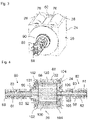
- FIG 2 shows an enlarged sectional view of FIG figure 1 shown exemplary embodiments of the process unit 20 with the process head 22.
- the process head 22 is rotatably mounted about an axis of rotation 58.
- the process head 22 is cylindrical and has an axis and a lateral surface that is formed on the radially outer edge of the process head 22 , the axis lying on the axis of rotation 58 .
- the process head can essentially form a right cylinder, the axis of which runs from a center point of its top surface to the center point of its base surface.
- the process head 22 can be drum-shaped.
- the process head 22 has a number of gas inlets 51 and a number of gas outlets 50 which are formed on the radially outer edge, for example on the lateral surface, of the process head 22 .
- the gas outlets 50 are designed and arranged in such a way that, during operation, a process gas leaves at least one of the gas outlets 50 in a direction with a radially directed directional component.
- the process head 22 can be between 1 mm and 10000 mm, for example between 10 mm and 1000 mm, for example between 100 mm and 500 mm wide in the axial direction.
- the radius of the process head 22 can be between 10 mm and 1000 mm, for example between 100 mm and 600 mm.
- the gas outlets 50 on the radially outer edge enable a surface treatment of the substrate 30 with low gas consumption and a high process speed, in particular if several reaction gases are required in succession per layer and/or if several identical or different layers have to be applied or removed one on top of the other.
- the process unit 20 can be made very compact and can therefore be easily inserted into an existing production line.
- a process gas can be blown out of the process head 22 in a radial direction, for example, that is to say perpendicular to the axis of rotation 58 .
- the process gas can only be partially blown out of the process head 22 in a radial direction, for example taking into account flow optimization when the process head 22 is rotating.
- the gas outlets 50 and/or the gas inlets 51 on the lateral surface can be designed in the form of slots.
- the gas outlets 50 can each have a slit (see figure 15 ) which extends in the axial direction across the lateral surface, for example parallel to the axis of rotation 58 and/or from one axial end of the process head 22 to the other axial end of the process head 22, and which extends in the radial direction from the outer circumference of the process head 22 into the process head 22 towards a plurality of channels 52, 54, 55, 56, 57 spaced apart from the radially outer edge of the process head 22, which serve to carry the gas outlets 50 for supplying or the gas outlets 51 for discharging the process gases to be connected to the gas ducts described further below.
- the slit-like design of the gas outlets 50 contributes to the substrate 30 arranged around the outer edge being coated evenly.
- the gas outlets 50 can be circular or angular (see FIG figure 16 ).
- the process head 22 can have a plurality of gas outlets 50, which have a first gas outlet 50a, which communicates with a first channel 52, for supplying a first reaction gas, and/or a second gas outlet 50b, which communicates with a second channel 55, for supplying a second reaction gas communicates.
- the process head 22 for supplying the first reaction gas or for supplying a third reaction gas have a third gas outlet 50c, which communicates with a third channel 56, and/or for supplying the second reaction gas or a fourth reaction gas, have a fourth gas outlet 50d, which communicates with a fourth channel 57, and/or for supplying of a flushing gas as a further or fifth process gas have one or more further or fifth gas outlets 50e which communicate with one or more fifth channels 54 .
- the gas outlets 50a, 50b, 50c, 50d, 50e make it possible, for example, to supply three different process gases, for example in an ALD process a first gaseous reactant as the first process gas and a second gaseous reactant as the second process gas for producing a material layer of a first material or a first Material combination and, as an additional process gas, a purge gas for purging.
- the first and second gaseous starting materials are also referred to as the first and second precursors.
- two further process gases can be supplied, for example a third precursor as the third process gas and a fourth precursor as the fourth process gas for producing a material layer of a second material or a second material combination.
- further gas outlets can be provided, for example two further educts can be supplied or several gas outlets can also be provided for one of the process gases.
- One or two of the gas inlets 51 on the outer edge of the process head 22 can be formed between the gas outlets 50 on the outer edge of the process head 22 .
- the gas inlets 51 can be slot-shaped and/or circular, corresponding to the gas outlets 50, and can extend in the axial direction across the lateral surface, for example parallel to the axis of rotation 58 and/or from one axial end of the process head 22 to the other axial end of the process head 22 , and itself in radial Direction from the outer periphery of the process head 22 into the process head 22 towards a plurality of spaced from the radially outer edge of the process head 22 corresponding channels 53, which serve to connect the gas inlets 51 at the outer edge of the process head 22 with gas passages described below .
- a fifth gas outlet 50e for the flushing gas can always be provided between two gas outlets 50a, 50b, 50c, 50d for the educts.
- a gas inlet 51 can be provided between the gas outlets 50a, 50b, 50c, 50d of the educts for sucking off the educts or the flushing gas.
- a first gas outlet 50a for the first educt For example, along the circumference of the radially outer edge, a first gas outlet 50a for the first educt, a gas inlet 51 for sucking off the first educt, a fifth gas outlet 50e for the flushing gas 50e, a further gas inlet 51 for sucking off the flushing gas, a second gas outlet 50b for the second educt, a further gas inlet 51 for sucking off the second educt, a further fifth gas outlet 50e for the flushing gas and a further gas inlet 51 for sucking off the flushing gas.
- This sequence can be repeated several times and/or additional gas outlets 50 can be provided for additional starting materials.
- the channels 52, 53, 54, 55, 56, 57 can extend through the process head 22 in the axial and/or radial direction.
- the channels 52, 53, 54, 55, 56, 57 can extend in the radial direction at the axial ends of the process head 22, in other words at the base and/or the top surface of the cylindrical shape, and from the axial ends of the process head 22 extend spaced apart in the axial direction.
- end bodies 101, 103 are arranged, which are coupled to the processing head 22 and which receive the radial parts of the channels 52, 53, 54, 55, 56, 57 and so the connect axially extending channels 52, 53, 54, 55, 56, 57 with the gas passages explained below.
- a first housing extraction 62 for extracting process gas from the housing 24
- a first housing purge gas feed line 64 for feeding purge gas into the housing 24
- a second housing suction device 66 for sucking gas out of the housing 24
- a second housing purge gas feed line 68 for feeding purge gas into the housing 24, which, for example, treated surface of the substrate 30 facing.
- Additional suction devices 62, 66 can also be arranged.
- the other suction devices 62, 66 can, for example, be arranged one after the other from the outside in or from the inside out, for example sequentially outwards, so that, according to the principle of differential pumping, the penetration of ambient air into the housing 24 and/or the escape of process gases from the Housing 24 is prevented. Furthermore, a suction device can be arranged in the housing 24 in such a way that the substrate 30 in the housing 24 is sucked away from the process head 22 , as a result of which a distance between the lateral surface of the process head 22 and the substrate 30 is specified.
- a third housing purge gas supply 70 for supplying purge gas into the housing 24 and/or a third housing suction device 72 for sucking gas out of the housing 24 can be provided, which are spaced apart from the feed device and/or which, for example can be arranged on a side of the substrate 30 facing away from the surface of the substrate 30 to be treated.
- the third housing suction 72 can help to suck the substrate 30 away from the process head 22 and/or the distance between the Substrate 30 and the lateral surface of the process head 22 to specify.
- the flushing gas can thus be supplied, for example, on the surface of substrate 30 to be coated, for example in the area of the feed device, for example between rollers 26, 28, and/or on the surface of substrate 30 not to be coated, for example at a distance from the feed device.
- a heating device 74 can be arranged in the housing 24 with which an interior of the housing 24 can be heated. Alternatively or additionally, the housing 24 can be heated with the aid of heated flushing gas. Alternatively or additionally, the process head 22 can be heated.
- a temperature in the housing 14 can be between 0° and 1000° C., for example between 20° and 500° C., for example between 150° and 250° C., for example around 200° C.
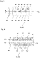
- FIG. 12 shows that the housing 24 can have a feed opening 78 for feeding the substrate 30 and a discharge opening 76 for discharging the substrate 30.
- the processing unit 20 can have a drive unit 90 for rotating the processing head 22 .
- the drive unit 90 can have, for example, a motor, a transmission, for example a gear or a transmission.
- the drive unit can be integrated into the housing 24 or act outside of the housing 24 on a rotary shaft, which lies on the axis of rotation 58, of the process head 22.
- one or two rotary feedthroughs 80, 82 (see figure 4 ) be provided.
- the rotary unions 80, 82 each have a rotatable inner body 81 which can be rotated about the axis of rotation 58 .
- the inner bodies 81 can be attached to the same rotary shaft as the process head 22 or the rotary feedthroughs 80, 82 can have their own rotary shafts which are mechanically coupled to the rotary shaft of the process head 22.
- the inner body 81 has a plurality of axially extending cavities 83 which are designed for supplying or removing process gases, which can also be referred to as gas passages and which are described further below with reference to FIG figure 6 be explained in more detail.
- FIG 4 shows further that the channels 52, 53, 54, 55, 56, 57, for example the channels 52, 56, extend in the axial direction through the process head 22 and that the process head 22 in the axial direction with a first end body 101 and with a second end body 103 is mechanically coupled, the two end bodies 101, 103 mechanically couple the process head 22 to the first and second rotary feedthrough 80, 82, respectively.
- the end bodies 101, 103 can have recesses 105, for example, which extend at least partially in the radial direction and via which the cavities 83 of the rotary leadthroughs 80, 82, i.e. via the gas leadthroughs, communicate with the channels 52, 53, 54, 55, 56, 57 be able.
- the recesses 105 form radial parts of the channels 52, 53, 54, 55, 56, 57.
- recesses can be on or near end faces of the process head 22, in other words on the base and/or the top surface the cylindrical shape of the process head 22, which form the radial parts of the channels 52, 53, 54, 55, 56, 57 and via which the cavities 83 of the rotary leadthroughs 80, 82 with the channels 52, 53, 54, 55, 56 , 57 can communicate.
- the device 10 has a web 102, 104 adjacent to the axially outer ends of the radially outer edge of the process head 22, each of which extends from the jacket of the Process head 22 protrudes in the radial direction and runs, for example, around the entire circumference or around sections of the circumference of the process head 22 .
- the webs 102, 104 serve as spacers for specifying the distance between the lateral surface of the process head 22 and the substrate 30.
- further spacers 140 can be provided (see figure 15 ).
- the substrate 30 can be guided at least partially around the process head 30 in such a way that it rests on the webs 102, 104 at its side edges of the surface to be coated that are not to be coated.
- the surface of substrate 30 to be coated, the lateral surface of process head 22 and webs 102, 104 then delimit one or more process spaces, for example a first process space 100 and a third process space 120, to which the process gases for treating the surface of substrate 20 are supplied during operation will.
- the webs 102, 104 are, for example, between 0.01 and 10 mm, for example between 0.05 and 5 mm, for example between 0.1 and 1 mm from the radially outer edge of the process head 22 in the radial direction, so that the process spaces when applied Substrate 30 has a height between 0.01 and 10 mm, for example between 0.05 and 5 mm, for example between 0.1 and 1 mm.
- the webs 102, 104 can have a width of between 1 and 20 mm, for example between 5 and 15 mm.
- the gas outlets 50 and gas inlets 51 are formed between the webs 102, 104, for example.
- the process spaces 100, 120 are defined and/or characterized by the volume in which a specific process gas is located and/or to which a specified process gas is to be supplied or in which one or two process gases are to be discharged.
- the process spaces 100, 120 rotate with the process head 22 and move over the substrate surface to be coated.
- one, two or more other corresponding webs can be arranged between the webs 102, 104, on which the substrate 30 can also be placed, for example to prevent the substrate 30 from sagging, which would reduce process spaces.
- the further webs can be arranged, for example, depending on the axial length of the process head 22, the width and/or the stability of the substrate 30 to be treated.
- fixing elements can be provided, which serve to fix the substrate 30 to the webs 102, 104 as it rotates around the process head 22 in the third and fourth direction 44, 46.
- the webs 102, 104 can have pins and the substrate 30 can have holes corresponding to the pins, so that the pins engage in the holes and the substrate 30 is fixed during the feed relative to the rotatably mounted webs 102, 104 and with the webs 102 , 104 is rotated as well, or this rotates as well, as is known from printers equipped with endless paper having holes.
- the fixing elements can also have one or more clamping devices, with the aid of which the substrate 30 can be clamped and/or tensioned in the axial direction, for example automatically clamped.
- FIG 5 shows an example of one of the rotary unions 80, 82 from the outside in a side view.
- the rotary union 80, 82 shown is divided into several segments in the axial direction, for example a first segment 84, a second segment 85, a third segment 86, a fourth segment 87, a fifth segment 88 and/or a sixth segment 89.
- the Segments 84-89 may have multiple port openings.
- the segments 84 to 89 can consist of a single piece or of several mechanically coupled individual pieces.
- a first port 94 on the first segment 84, a second port 95 on the second segment 85, a third port 96 on the third segment 86, a fourth port 97 on the fourth segment 87, a fifth port 98 on the fifth segment 88 and/or a sixth port 99 may be formed on the sixth segment 89.
- the inner body 81 can be rotated relative to the segments 84 to 89 so that the segments 84 to 89 can remain stationary during the operation of the process unit 20 and thus during a rotation of the process head 22 and the inner body 81 .
- FIG. 6 shows a section through the illustrated rotary union 80, 82 according to figure 5 along the cutting edge AA shown there.
- the segments 84 to 89 have several inner grooves, via which the connection openings 94 to 99 can be connected to the cavities 83 (see figure 4 ) communicate, the cavities 83 having, for example, a first gas passage 123 and/or a fourth gas passage 126.
- the first segment 84 has a first inner groove 114, via which the first connection opening 94 communicates with the first gas passage 123
- the second segment 85 has a second inner groove 115, via which the second connection opening 95 communicates with a second gas passage, not shown
- the third segment 86 has a third inner groove 116, via which the third connection opening 96 communicates with a third gas passage, not shown
- the fourth segment 87 has a fourth inner groove 117, via which the fourth connection opening 97 communicates with the fourth gas passage 126
- the The fifth segment 88 has a fifth inner groove 118, via which the fifth connection opening 98 communicates with a fifth gas passage, not shown
- the sixth segment 89 has a sixth inner groove 119, via which the sixth connection opening 99 communicates with a sixth gas passage, not shown communicates.
- the inner grooves 114 to 119 ensure that process gases can be permanently supplied to the process head 22 via the connection openings 94 to 99 and the gas passages 123 , 126 , even when the inner body 81 is rotating, or can be discharged from the process head 22 .
- transverse walls 131 can be formed, for example, which divide the circumference of the process head 22 into several segments.
- the transverse walls 131 can protrude from the lateral surface in the radial direction and can extend in a direction with a directional component in the axial direction, ie bear tangentially on the lateral surface.
- the transverse walls 131 can extend in the axial direction from the web 102 to the web 104 and/or stand perpendicular to the webs 102, 104, for example.
- the transverse walls 131 can, for example, have a lower height than the webs 102, 104.
- the transverse walls 131 with the webs 102, 104, with the lateral surface of the process head 22 and with the surface of the substrate 30 to be treated can have individual process spaces 100, 120 more from each other or less delimited.
- segmented process spaces 100, 120 can be formed on the outer circumference, in which different pressures can be generated one after the other and, for example, different process gases can be supplied or sucked off.
- the first process space 100, a second process space 110, the third process space 120 and/or a fourth process space 130 can be formed in this way.
- Further process rooms can be formed between the process rooms 100, 110, 120, 130, for example one, two or more fifth process rooms 134 and/or one, two or more sixth process rooms 132.
- a first, a second, a third or a fourth reaction gas for treating the surface of the substrate 30 can be supplied to the first to fourth process spaces 100, 110, 120, 130 via the first to fourth gas inlets 50a, 50b, 50c, 50d.
- the first to fourth process chambers 100, 110, 120, 130 can, for example, be supplied with only one reaction gas or two in alternation.
- a flushing gas can be supplied to the fifth process chambers 134 as a fifth or further process gas, for example via the fifth gas inlets 50e.
- the fifth process spaces 134 can also be referred to as flushing areas.
- a negative pressure can be permanently generated via the gas inlets 51, or at least a lower pressure than in the preceding process chamber, so that the previously supplied process gases can be sucked off in the sixth process chambers 132.
- the sixth process spaces 132 can also be referred to as negative pressure areas.
- a gas inlet 51 for sucking off process gas can be arranged within the sixth process chambers 132 near the transverse walls 131 that delimit the sixth process chambers 132 .
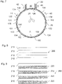
- a region of the substrate 30 in which a predetermined position A on the substrate is arranged adjoins the first process space 100 .
- the first reaction gas in the first process chamber 100 to the predetermined position A of the substrate.
- the region of the substrate 30 with the predetermined position A borders on another of the process spaces, so that another process gas impinges on the predetermined position A.
- the first layer structure 200 has, for example, a plurality of first layers 210 which each consist of the same first material or of the same first combination of materials.
- each first layer 210 forms a complete ALD layer, which is formed, for example, from the reaction of two educts and/or which is formed, for example, during a single rotation of the process head 22 .
- the second layer structure 202 has, for example, a plurality of first layers 210 each made of the first material or the first material combination, and a plurality of second layers 220 each made of a second material or a second material combination.
- the first and second layers 210, 220 are alternately and alternately arranged one after the other.
- every second layer 220 forms a complete ALD layer, which is formed, for example, from the reaction of a further reactant with a previous one or from the reaction of two further reactants and/or which is formed, for example, during a single rotation of the process head 22 .
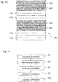
- the 10 12 shows an exemplary embodiment of a third layer structure 204 which is produced when the surface of the substrate 30 is treated and with which the surface of the substrate 30 is coated.
- the third layer structure 204 has, for example, a plurality of the first layers 210, which each consist of the first material or the first combination of materials, and a plurality of the second layers 220, which each consist of the second material or the second combination of materials.
- several of the first layers 210, which form a first stack of layers, and several of the second layers 220, which form a second stack of layers are arranged one after the other, with several of these stacks of layers being arranged alternately and alternately one after the other.
- layer structures 200, 202, 204 As an alternative or in addition to the layer structures 200, 202, 204 shown above, further layer structures 200, 202, 204 are conceivable which, for example, have layer structures with more or fewer layers and/or with more or less different layers, i.e. with different materials.
- the mode of operation of device 10 for treating the surface of substrate 30 and the production of layer structures 200, 202, 204 are explained in more detail below in connection with a method for treating the surface of substrate 30, the method being carried out, for example, with the aid of device 10 explained above or can be performed with an alternative device.
- the layer structures 200, 202, 204 are produced in the method for treating the surface of the substrate 30, which contributes, for example, to producing the optoelectronic component that has the substrate 30 with one of the layer structures 200, 202, 204.
- 11 12 shows a flow chart of an embodiment of an exemplary method for treating the surface of the substrate 30.
- the method can be carried out, for example, with the aid of the device 10 described above.
- the substrate 30 can be introduced into the device 10, for example into the process unit 20.
- the substrate 30 can be introduced into the process unit 20, for example via the feed opening 78, in such a way that the substrate 30 first moves between the first roller 28 and the intermediate piece 60, then between the process head 22 and the first roller 28 and then between the process head 22 and an inner wall of the case 24 pushes or is pushed.
- the substrate 30 is placed at least partially around the lateral surface of the process head 22 and optionally on the webs 102, 104 that a Coating surface of the substrate 30, which faces the process head 22, and the lateral surface of the process head 22 and optionally the webs 102, 104 and optionally the transverse walls 131, the process spaces 100, 110, 120, 130, 132, 134 form.
- Purge gas e.g. inert gas
- a rotational frequency of the process head 22 can be in a range between 1 and 1000 rpm, for example between 100 and 500 rpm, for example between 150 and 250 rpm or 200 rpm.
- the process head 22 can be rotated in the direction of rotation 25 which is opposite to the direction of feed of the substrate 30 or opposite to the direction of rotation 25 .
- the surface of the substrate 30 is treated.
- the surface of the substrate 30 can be at least partially removed or the surface of the substrate 30 can be coated.
- one, two or more process gases can be supplied to or removed from the process spaces 100, 110, 120, 130, 132, 134, for example.
- pressures of 0.001 to 5 bar for example 0.01 to 2 bar, for example 0.1 to 1.5 bar, can be generated in the corresponding process spaces.
- pressures of 0.0005 to 4.95 bar, for example 0.005 to 1.95 bar, for example 0.01 to 1.45 bar can be generated in the sixth process chambers 132 .
- the stated pressure data refer to absolute pressures. Decisive for an effective reduction or prevention of a mixture and / or entrainment of the process gases and / or an effective supply or removal
- process gases from the process space(s) can also be the differential pressures between the individual process spaces. For example, if the process rooms are not discretely separated from each other, but rather merge more or less continuously into one another.
- Such a differential pressure can be, for example, between 0.001 and 1 bar, for example between 0.01 and 0.1 bar, for example between 0.05 and 0.08 bar.
- a differential pressure can, for example, also be a pressure difference between two pressures at a predetermined position, for example at the predetermined position A, on the substrate 30 at different points in time. If the removal process is carried out, this can be, for example, a dry etching process, for example chemical dry etching.
- the substrate 30 can be guided out of the process unit 20 in a step S8.
- the substrate 30 is first guided between the process head 22 and the second roller 28 , then between the second roller 28 and the intermediate piece 60 and then out of the housing 24 via the discharge opening 76 .
- the substrate 30 is fed in and removed, for example, without the substrate 30 being singulated, as a result of which a roll-to-roll process is possible.
- the substrate 30 can be fed into and removed from the housing 24 continuously or in a clocked manner.
- the feed of the substrate 30 may or may not be interrupted during the surface treatment.
- the feed of the substrate 30 can be clocked, so that successive elongated regions of the substrate 30 are treated.
- a plurality of layers of the same or different material or the same or different material combinations can be deposited on the substrate 30 during one cycle by supplying the process gases and during coating by depositing the corresponding atoms and/or molecules or be removed when removing it.
- the substrate 30 can be pushed further continuously, for example at a constant feed rate.
- several layers of the same or different material or the same or different material combinations can be deposited on the substrate or removed from it, provided that the peripheral speed, i.e. the speed at which, for example, the gas outlets 50 and/or gas inlets 51 move, of the process head 22 is greater than the feed speed of the substrate 30.
- the first to fourth layer structures 200 to 204 can be produced independently of the feed types explained above.
- An average feed speed of the substrate 30 can be in a range between 0 and 100 m/min, with 0 m/min being able to occur at times with clocked feed, for example between 0.1 and 10 m/min, for example between 0.5 and 5 m/min.
- the peripheral speed of the process head 22 can be greater than the feed speed of the substrate 30.
- a layer growth of 0.1 nm/cy is possible, for example.
- an ALD layer thickness of 20 nm can be achieved after 60 s.
- the circumference of the lateral surface is 69.1 cm, resulting in a substrate coating length of approximately 0.6 m.
- a layer growth of 20 nm with a coating speed of 0.6 m/min is possible for the roll-to-roll process.
- One of the process spaces 100, 110, 120, 130 moves over a predetermined point on the substrate 30 in 24 ms, for example.
- the coating speed is 5*0.6 m/min, i.e. 3 m/min, i.e. large-scale production lines can be implemented. If these parameters are assumed, the individual processes can be partially carried out at room temperature, depending on the precursors used.
- the substrate 30 with the treated surface can be separated.
- the treated substrate 30 may be unrolled and/or cut, sawn, or etched.
- FIG. 12 shows a flow chart of an exemplary embodiment of a method for coating the surface of the substrate 30, which can be carried out, for example, in step S6 of the method explained above.
- the coating method can be a CVD process or an ALD process, for example.
- monoatomic or multiatomic layers can be applied, which can be a few angstroms up to several nanometers thick.
- 100 to 200 identical or different superimposed layers can be applied to the substrate 30, for example according to the first to third layer structures 200, 202, 204.
- the flowchart abstractly describes the coating process as seen from a position on the substrate 30 specified by way of example, for example as seen from the specified position A.
- the process spaces mentioned move over the specified position A during the process.
- the individual steps are carried out continuously, but the process spaces rotate over the substrate 30, so that seen from the specified position A on the substrate 30, a chronological sequence of the individual steps.
- the flowchart therefore runs at different positions on the substrate 30 at different times.
- the method represents an idealized process sequence in which the process gases are not carried over from one process chamber to the other, which can be achieved, for example, at least almost with the aid of the transverse walls 131 .
- a first gaseous educt, then a purge gas and then a second gaseous educt can be supplied in succession, for example to produce the first layer 210 via the rotating process head 22 .
- the educts can also be referred to as precursors.
- the first educt can have water, for example, and the second educt can have trimethyl aluminum (TMA), for example, which means that an Al 2 O 3 layer can be produced.
- TMA trimethyl aluminum
- TiCl 4 for example, can be used as the second starting material.
- the first process gas can be supplied, which corresponds to the first educt, for example the first reaction gas.
- the first process gas can be supplied to the first process space 100, for example. Atoms and/or molecules of the first process gas can thereby be deposited on the surface of the substrate 30 to be treated.
- the surface of the substrate 30 to be coated is saturated with the gas atoms or gas molecules of the first gaseous starting material.
- the first starting material can contain steam, oxygen or ozone, for example.
- the first process gas can be extracted, for example via the sixth process chamber 132, which follows the first process chamber 100 in the opposite direction to the direction of rotation 25.
- the flushing gas can be supplied, which mixes with the remaining first process gas.
- the flushing gas can be supplied, for example, to the fifth process chamber 134 following the first process chamber 100 in the opposite direction to the direction of rotation 25 .
- the flushing gas largely prevents a mixture of different educts. In other words, mixing of the substances or gas atoms or gas molecules of the gaseous precursors and thus an undesired gas phase reaction is prevented by the flushing gas. In addition, this ensures that one of the process gases is quickly removed before the next process gas is fed in.
- An inert gas can be used as the flushing gas.
- Step S16 and further steps, in which purge gas is supplied can generally also be referred to as "purge" steps.
- the flushing gas can be extracted with the remaining first process gas, for example via the sixth process chamber 132 following the aforementioned fifth process chamber 134 in the opposite direction of rotation of, for example, 0.001 to 1 bar can be generated.
- the differential pressure for example, a pressure difference between two pressures at the given position A on the substrate 30 at different times.
- the second process gas can be supplied, which corresponds to the second starting material, for example the second reaction gas.
- the second process gas can be supplied to the second process space 110, for example. Atoms and/or molecules of the second process gas can be deposited on the layer of the first starting material and form a connection with it, as a result of which the first layer 210 is formed, for example with a single rotation of the process head 22. As a result, the first layer 210 can, for example be formed monoatomically.
- the second starting material can be TMA, for example.
- the second process gas can be extracted, for example via the sixth process chamber 132, which follows the second process chamber 110 in the opposite direction to the direction of rotation 25.
- the flushing gas can be supplied, which mixes with the remaining second process gas.
- the flushing gas can be supplied, for example, to the fifth process chamber 134 following the second process chamber 120 in the opposite direction to the direction of rotation 25 .
- the flushing gas can be extracted with the remaining second process gas, for example via the sixth process chamber 132, which follows the aforementioned fifth process chamber 134 in the opposite direction to the direction of rotation 25.
- the first and the second educt can, for example, be repeatedly supplied several times in succession in order to produce a plurality of layer sequences of the first layer 210 .
- steps S12 to S26 can be carried out several times in succession.
- steps S12 to S26 can be carried out each time the process head 22 rotates. This allows for one revolution Apply layer of a first ALD layer, for example according to the first layer structure 200.
- steps S12 to 26 can be carried out several times during one revolution, for example by the first and the second process gas being supplied via more of the gas outlets 50. This makes it possible, for example, to apply two or more layers of the first ALD layer during one revolution, for example according to the first layer structure 200.
- the one or more ALD layers can be formed alternatively or additionally during several revolutions.
- the coating can take place, for example, during the clocked feed of the substrate 30 .
- the substrate 30 is in each case only conveyed further by a distance which corresponds approximately to the circumference of the process head 22, but the substrate 30 is not conveyed further during the coating process.
- the process head 22 is then only supplied with the process gases required for the respective layer, while all other process spaces, inlets and outlets are flushed or sucked off with flushing gas, for example. This allows layers of any thickness to be realized.
- gaseous starting materials can also be supplied in order to produce different layers.
- two or more further layers can be formed during one or more revolutions of the process head 22, for example according to the second layer structure 202, and/or further layers can be formed from the same material(s) or material combinations during subsequent revolutions, for example according to the third layer structure 204. This allows to deposit multiple layers of a first ALD layer and then multiple layers of a second ALD layer.
- the third process gas can be supplied, which is a third educt corresponds, for example, the third reaction gas.
- the third process gas can be supplied to the third process space 120, for example. Atoms and/or molecules of the third process gas can be deposited on the first layer 210 in this case.
- the first layer 210 is saturated with the third gaseous starting material.
- the third process gas can be extracted, for example via the sixth process chamber 132, which follows the third process chamber 120 in the opposite direction to the direction of rotation 25.
- the flushing gas can be supplied, which mixes with the remaining third process gas.
- the flushing gas can be supplied, for example, to the fifth process chamber 134 following the third process chamber 110 in the opposite direction to the direction of rotation 25 .
- the flushing gas can be extracted with the remaining third process gas, for example via the sixth process chamber 132, which follows the aforementioned fifth process chamber 134 in the opposite direction of rotation.
- a negative pressure or a differential pressure of an amount of, for example, 10 up to 100 mbar can be generated.
- the fourth process gas can be supplied, which corresponds to a fourth reactant, for example the fourth reaction gas.
- the fourth process gas can be supplied to the fourth process space 130, for example.
- Atoms and/or molecules of the fourth process gas can be deposited on the layer of the third educt and form a compound with it, as a result of which, for example, the second layer 220 is formed, for example with a single rotation of the process head 22.
- the second layer 220 for example, be formed monoatomically.
- the fourth process gas can be extracted, for example via the sixth process chamber 132 following the fourth process chamber 130 in the opposite direction to the direction of rotation 25.
- the purge gas can be supplied, which mixes with the remaining fourth process gas.
- the flushing gas can be supplied, for example, to the fifth process chamber 134 following the fourth process chamber 130 in the opposite direction to the direction of rotation 25 .
- the flushing gas can be extracted with the remaining fourth process gas, for example via the sixth process chamber 132 following the aforementioned fifth process chamber 134 in the opposite direction to the direction of rotation 25.
- the third and the fourth educt can, for example, be repeatedly supplied several times in succession in order to produce several layers 220 of the second layer 220 .
- steps S30 to S44 can be carried out several times in succession. This enables multiple layers 220 of a second ALD layer to be applied.
- steps S12 to S26 and/or S30 to S44 can be carried out several times in succession in order to form the different layer structures 200, 202, 204 from ALD layers.
- the layers 210, 220 can form one, two or more electrode layers, organically functional layers, optical layers, such as reflection layers or transmission layers, layers of thin film transistors, barrier layers and/or encapsulation layers or thereon be educated.
- the electrode layer can be made of an electrically conductive material are or be formed, such as from a metal or a conductive transparent oxide (transparent conductive oxide, TCO) or a layer stack of several layers of the same metal or different metals and/or the same TCO or different TCOs.
- Transparent conductive oxides are transparent conductive materials, for example metal oxides such as zinc oxide, tin oxide, cadmium oxide, titanium oxide, indium oxide, or indium tin oxide (ITO).
- ternary metal oxygen compounds such as AlZnO, Zn2SnO4, CdSnO3, ZnSnO3, MgIn2O4, GaInO3, Zn2In2O5 or In4Sn3O12 or mixtures of different transparent conductive oxides belong to the group of TCOs and can be used in various embodiments be used.
- the TCOs do not necessarily correspond to a stoichiometric composition and can also be p-doped or n-doped.
- the electrode layer can have, for example, Ag, Pt, Au, Mg, Al, Ba, In, Ag, Au, Mg, Ca, Sm or Li, as well as compounds, combinations or alloys of these materials.
- the electrode layer can be formed from a layer stack of a combination of a layer of a metal on a layer of a TCO, or vice versa.
- An example is a silver layer applied to an indium tin oxide (ITO) layer (Ag on ITO) or ITO-Ag-ITO multilayers.
- ITO indium tin oxide
- the electrode layer can provide one or more of the following materials as an alternative or in addition to the materials mentioned above: networks of metallic nanowires and nanoparticles, for example of Ag; carbon nanotube networks; graphene particles and layers; Networks of semiconducting nanowires. Furthermore, the electrode layer can have electrically conductive polymers or transition metal oxides or electrically conductive transparent oxides.
- an organically functional layer can contain one or more emitter layers, for example with fluorescent and/or phosphorescent emitters, and one or more hole conduction layers (also referred to as hole transport layer(s)) and/or one or more electron conduction layers (also referred to as electron transport layer (s)).
- emitter layers for example with fluorescent and/or phosphorescent emitters
- hole conduction layers also referred to as hole transport layer(s)
- electron conduction layers also referred to as electron transport layer (s)
- emitter materials that can be used for the emitter layer(s) include organic or organometallic compounds such as derivatives of polyfluorene, polythiophene and polyphenylene (eg 2- or 2,5-substituted poly-p-phenylenevinylene) and metal complexes such as iridium -Complexes such as blue phosphorescent FIrPic (bis(3,5-difluoro-2-(2-pyridyl)phenyl-(2-carboxypyridyl)iridium III), green phosphorescent Ir(ppy)3 (tris(2-phenylpyridine)iridium III ), red phosphorescent Ru (dtb-bpy)3*2(PF6) (tris[4,4'-di-tert-butyl-(2,2')-bipyridine]ruthenium(III) complex), and blue fluorescent DPAVBi ( 4,4-bis[4-(di-p-tolylamino)st
- the organically functional layer can generally have one or more functional layers.
- the one or more functional layers may comprise organic polymers, organic oligomers, organic monomers, organic small, non-polymeric molecules ("small molecules") or a combination of these materials.
- the organically functional layer can have one or more functional layers, which is or are designed as a hole transport layer, so that, for example in the case of an OLED, an effective Hole injection is made possible in an electroluminescent layer or an electroluminescent region.
- the organically functional layer can have one or more functional layers which is or are designed as an electron transport layer, so that, for example in an OLED, effective electron injection into an electroluminescent layer or an electroluminescent region is made possible.
- the organically functional layer can have one or more functional layers which is or are designed as an electron transport layer, so that, for example in an OLED, effective electron injection into an electroluminescent layer or an electroluminescent region is made possible.
- tertiary amines, carbazole derivatives, conducting polyaniline or polyethylenedioxythiophene can be used as the material for the hole transport layer.
- the one or more functional layers can be embodied as an electroluminescent layer.
- an encapsulation layer can have or consist of one of the following materials: aluminum oxide, zinc oxide, zirconium oxide, titanium oxide, hafnium oxide, tantalum oxide, lanthanum oxide, silicon oxide, silicon nitride, silicon oxynitride, indium tin oxide, indium zinc oxide, aluminum-doped zinc oxide, and mixtures and alloys thereof.
- the encapsulation layer or (in the case of a layer stack with a plurality of sub-layers) one or more of the sub-layers of the encapsulation layer can have one or more high-index materials, in other words one or more materials with a high refractive index, for example with a refractive index of at least 2 , for example MoO 3 .
- a barrier layer can have or consist of one or more of the following materials: aluminum oxide, zinc oxide, zirconium oxide, titanium oxide, hafnium oxide, tantalum oxide, lanthanum oxide, silicon oxide, silicon nitride, silicon oxynitride, indium tin oxide, indium zinc oxide, aluminum-doped Zinc oxide, and mixtures and alloys thereof.
- Oxygen sources such as H 2 O, H 2 O 2 , N 2 O 4 , N 2 O, O 2 , O 3 , CH 3 COOH, ROH (with R equal to CH 3 , CH 2 OHCH 2 OH, tC 4 H 9 OH or nC 4 H 9 OH) or metal alkoxides, to form nitrides nitrogen sources such as NH 3 , (CH 3 )NNH 2 , tBuNH 2 or CH 2 CHCH 2 NH, for the formation of pure metals, for example H 2 , B 2 H 6 , silanes or hydrides, for the formation of sulfides, selenides or tellurides, for example H 2 S, H 2 Se or H 2 Te can be used.
- nitrogen sources such as H 2 O, H 2 O 2 , N 2 O 4 , N 2 O, O 2 , O 3 , CH 3 COOH, ROH (with R equal to CH 3 , CH 2 OHCH 2 OH, tC 4 H 9
- (CH 3 ) 3 Al, (CH 3 ) 2 AlCl, (CH 3 ) 2 AlH or (CH 3 CH 2 ) 3 Al can be supplied as second precursors and/or second reaction gas, for example for the formation of Al 2 O 3 for the formation of ZnO, for example (CH 3 ) 4 Zn, (CH 3 CH 2 ) 4 Zn or (C 2 H 5 ) 2 Zn, for the formation of ZrO 2 for example (C 5 H 5 ) 2 ZrCl 2 , (C 5 H 5 ) 2 Zr(CH 3 ) 2 , Zr[(C 2 H 5 )(CH 3 )N] 4 , ZrCl 4 or Zr(CH 3 C 5 H 4 ) 2 CH 3 OCH 3 are supplied for formation of TiO2/TiN, for example Ti(OCH(CH 3 ) 2 ) 4 , Ti[N(CH 3 ) 2 ] 4 , TiCl 4 or [(C 2 H 5 ) 2 N] 4 Ti, to form H
- TaCl 5 or (CH 3 ) 3 CNTa(N(C 2 H 5 ) 2 ) 3 are supplied to form La 2 O 3 e.g. (C 5 H 5 ) 3 La or (C 5 MeH 4 ) 3 La are supplied, to form SiO 2 /SiN, for example SiCl 4 , Si(O(CH 2 ) 3 CH 3 ) 4 , ((CH 3 ) 3 CO) 3 SiOH, (CH 3 CH 2 C (CH 3 ) 2 O) 3 SiOH or (HSiCH 3 O) 4 are supplied, for the formation of SnO 2 e.g.
- (CH 3 ) 4 Sn or (CH 3 CH 2 ) 4 Sn are supplied, for the formation of ITO for example In(OCCH 3 CHOCCH 3 ) 3 , (CH 3 ) 4 Sn or (CH 3 CH 2 ) 4 Sn are supplied, to form MgO, for example (C 5 H 5 ) 2 M 9 are supplied, to form Sc 2 O 3 , for example (C 5 H 5 ) 3 Sc, for the formation of Y 2 O 3 , for example (C 5 H 5 ) 3 Y or (C 5 MeH 4 ) 3 Y, for the formation of Pt, for example (C 5 MeH 4 )PtMe 3 or C 5 H 4 CH 3 Pt(CH 3 ) 3 are supplied to form NiO, for example (C 5 H 5 ) 2 Ni or Ni(C 5 H 4 C 2 H 5 ) 2 are supplied to form V 2 O 5 for example OV(OCH(CH 3 ) 2 ) 3 are supplied, for the formation of Fe 2 O 3 for example ⁇ (CH 3
- a partial vacuum can be generated in the corresponding process chambers to almost vacuum or not. Furthermore, multiatomic layers can be formed.
- 13 12 shows an exemplary embodiment of the device 10 for treating the surface of the substrate 30, which has a plurality of process units 20 arranged in a row with process heads 22 correspondingly arranged in a row.
- the fact that the process heads 22 are arranged in a row means that the substrate 30 successively runs through the individual process units 20 past the corresponding process heads 22 .
- the process heads 22 are arranged, for example, so that the same side of the substrate 30 is treated by the or one of the subsequent process heads 22 as by the preceding process head 22. This allows further layers and/or, for example, alternating layers Layers or stacks of layers are applied or a previously applied layer can be completely or partially removed. Alternatively or additionally, with the layer structure remaining the same, the layers can be applied more quickly overall, for example the feed rate can be increased.
- 14 12 shows a further exemplary embodiment of the device 10 for treating the surface of the substrate 30, which has a plurality of process units 20 arranged in a row with process heads 22 correspondingly arranged in a row.
- the process heads 22 are arranged, for example, in such a way that the other side of the substrate 30 and thus another surface of the substrate 30 is treated by the or one of the subsequent process heads 22 as by the preceding process head 22. This means that layers can be applied to the other surface of the substrate 30 be applied or a layer previously applied to the other side can be completely or partially removed.
- 15 12 shows an exemplary embodiment of a process head, for example the process head 22, in a side view, with the substrate 30 only being indicated in a sectional view.
- the transverse walls 131 are only optionally arranged and in the figure 15 shown dashed.
- One of the gas outlets 50 and one of the gas inlets 51 are each formed by a slot-shaped recess.
- a plurality of spacers 140 are arranged around the circumference of the process head 22 .
- the spacers 140 serve to specify a distance between the substrate 30 and the process head 22 and thus a height of the process spaces 110 , 132 , 134 .
- the spacers 140 can be arranged in addition to or as an alternative to the webs 102, 104.
- the transverse walls 131 can also assume the function of the spacers 140 .
- the spacers 140 are spherical and rotatable in corresponding recesses of the process head 22 stored, so that friction between the spacers 140 and the substrate 30 can be kept low during operation.
- the spacers 140 can, for example, also be designed in the shape of a roller and/or extend, for example, parallel to the axis of rotation 58, in which case the spacers 140 can then also be rotatably mounted in corresponding recesses of the process head 22.
- the spacers 140 can also contribute to being able to process relatively wide substrates 30 .
- the process head 22 shows a further exemplary embodiment of a process head, for example the process head 22, in a side view, with the substrate 30 only being indicated in a sectional view.
- the process head 22 has a lateral surface that is concave, that is to say inwardly curved. This can contribute, for example, to the fact that the substrate 30 can sag inward and that the desired height of one or more of the process spaces 100, 110, 132, 134 is nevertheless ensured.
- the gas inlets 50 and/or the gas outlets 51 are formed, for example, by circular recesses. In addition, several circular recesses each form one of the gas inlets 50 or gas outlets 51.
- the circular recesses can be formed in addition to or as an alternative to the slot-shaped recesses. Furthermore, more or fewer and/or larger or smaller recesses can be formed. Furthermore, the recesses can be formed with larger or smaller distances from one another. Irrespective of the shape of the recesses, the recesses themselves and/or their courses and/or extensions in the process head 22 can be designed to take into account a gas flow during operation. For example, the recesses can be designed to be flow-optimized. For example, the widths of the openings of the slots may vary in the direction perpendicular to the axis 58.
- the spacers 140 are formed, for example, such that the substrate 30 has a distance of between 0.01 and 10 mm, for example between 0.05 and 5 mm, for example between 0.1 and 1 mm, from the lateral surface of the process head 22 .
- the process space(s) then have a height of between 0.01 and 10 mm, or between 0.05 and 5 mm, or between 0.1 and 1 mm.
- the distance of the substrate 30 from the process head 22 can be predetermined by the substrate 30 being sucked away from the process head 22 with the aid of a negative pressure on the side of the substrate 30 facing away from the process head 22 .
- the process spaces mentioned can be separated from one another to a greater or lesser extent.
- the separation can be relatively extensive, for example with the help of the transverse walls 131, so that the process spaces are discretely separated from one another, for example.
- the separation can also be reduced, for example with a decreasing height of the transverse walls 131. This can go so far, for example, that the transverse walls 131 no longer separate the process spaces from one another and/or the transverse walls 131 are dispensed with entirely.
- the individual process rooms then merge continuously into one another.
- the process spaces are then identified and/or defined by the gas cushions, in which one of the process gases is located or in which the process gases are discharged.
- a pressure in the housing 24 can be greater or less than an ambient pressure of the housing 24 .
- an average pressure in the process spaces can correspond approximately to the pressure in the housing 24 .
- the average pressure in the process spaces can be between 0.001 and 5 bar, for example between 0.01 and 2 bar.
- the pressure in the area of the gas outlets 50 can be greater than in the area of the gas inlets 51, for example so that there is a sufficient flow and/or there is no accumulation of precursors in purge gas spaces, i.e. process spaces to which purge gas is supplied.
- an average pressure of the flushing gas can be kept higher than an average pressure of the precursors.
- a flow of the flushing gas can be set to be greater than a flow of the precursors, as a result of which, for example, carryover can be kept low or prevented.
- FIG. 12 is a diagram showing a principle of operation of the apparatus 10 for surface treatment of the substrate 30. Also illustrated figure 17 the entrainment of the process gases during operation of the device 10. In particular figure 17 the dependence of the concentration c of the process gases on the time t at the specified position A on the substrate 30.
- the substrate 30 can be stationary, for example in clocked feed mode, or the substrate 30 can move, for example with one of the feed speeds mentioned above.
- the process spaces move across the specified position A, so that different process gases in different concentrations are moved across the specified position A on the substrate 30 over the course of time.
- gas cushions which have different concentrations of process gases, are moved over the predetermined position A on the substrate 30 over time.
- the different concentrations also occur, but at different times, the diagrams corresponding to the individual other positions relating to the in figure 17 diagram shown are shifted in time and/or phase.
- a first time interval 210 the concentration c of the first reaction gas at position A, which is shown as a dash-dot line, increases up to a maximum value, which is then maintained for a predetermined period of time.
- the period of time is essentially specified by the rotational speed of the process head 22 .
- the first process space 100 moves past the predetermined position A, as shown in FIG figure 7 shown.
- the first reaction gas is sucked off, for example while the sixth process chamber 132 adjoining the first process chamber 100 moves past the predetermined position A.
- the first reaction gas is therefore carried over from the first process chamber 100 to the subsequent sixth process chamber 132 .
- scavenging gas is sucked in from the fifth process chamber 134 following the sixth process chamber 132, which represents a carry-over of the scavenging gas.
- the first reaction gas and the flushing gas are mixed.
- the concentration c of the flushing gas is at its maximum at the position A, which is shown as a solid line and which is then maintained for a predetermined period of time.
- the period of time is essentially specified by the rotational speed of the process head 22 .
- the first reaction gas is completely or almost completely sucked off, so that a mixture of the first reaction gas with the second reaction gas to be subsequently supplied in the gas phase is avoided.
- the fifth process space 134 located between the first and second process space 100, 110 moves beyond the predetermined position A.
- the flushing gas is sucked out, for example while the sixth process space 132 in front of the second process space 110 moves past the predetermined position A.
- the flushing gas is therefore carried over from the fifth process chamber 134 to the subsequent sixth process chamber 132 .
- the second reaction gas is sucked in from the second process chamber 110 following the sixth process chamber 132, which represents a carry-over of the second reaction gas. Mixing of the second reaction gas and the flushing gas thus occurs in the sixth process space 132 located in front of the second process space 110 .
- the concentration c of the second reaction gas shown as a double-dash line is maximum, and then the maximum concentration c is maintained for a predetermined period of time.
- the period of time is essentially specified by the rotational speed of the process head 22 .
- the second process space 110 moves past the predetermined position A.
- the second reaction gas is drawn off, for example while the sixth process chamber 132, which adjoins the second process chamber 110, extends beyond the specified position A moved away.
- the second reaction gas is therefore carried over from the second process chamber 110 to the subsequent sixth process chamber 132 .
- scavenging gas is sucked in from the fifth process chamber 134 following the sixth process chamber 132, which represents a carry-over of the scavenging gas.
- the second reaction gas and the flushing gas are mixed.
- a first ALD layer is applied at the predetermined position A, for example.
- a further ALD layer can then be applied to the predetermined position on the substrate 30, for example a layer of the same material using the same reaction gases, for example using the first and second reaction gases, or a layer of a different material using other reaction gases. for example with the aid of the third and fourth reaction gases.
- the concentration c of the flushing gas is at its maximum at the position A, which is then maintained for a predetermined period of time.
- the period of time is essentially specified by the rotational speed of the process head 22 .
- the second reaction gas is sucked off completely or almost completely, so that a mixture of the second reaction gas with the reaction gas subsequently supplied to the substrate 30 at the predetermined position A in the gas phase is avoided.
- the fifth process space 134 located between the second and third process space 110, 120 moves beyond the predetermined position A.
- the flushing gas is sucked off, for example during the sixth process space 132 located in front of the third process space 120 is moved beyond the predetermined position A.
- the flushing gas is carried over from the fifth process chamber 134 to the subsequent sixth process chamber 132 .
- the process gas located there for example the third reaction gas, is sucked in from the third process space 120 following the sixth process space 132, which represents a carry-over of the third reaction gas. Mixing of the third reaction gas and the flushing gas thus occurs in the sixth process space 132 located in front of the third process space 120 .
- the concentration c of the third reaction gas which is shown as a dash-dot line, increases at position A up to a maximum value, which is then maintained for a predetermined period of time.
- the period of time is essentially specified by the rotational speed of the process head 22 .
- the third process space 120 moves past the predetermined position A.
- the first reaction gas can also be fed in again at the predetermined position A in the fifth time interval 250 .
- the third reaction gas is sucked off, for example while the sixth process space 132 adjoining the third process space 120 moves past the predetermined position A.
- the third reaction gas is therefore carried over from the third process chamber 120 to the subsequent sixth process chamber 132 .
- scavenging gas is sucked in from the fifth process chamber 134 following the sixth process chamber 132, which represents a carry-over of the scavenging gas. Therefore, the third process space 100 occurs in the following sixth process chamber 132 a mixing of the third reaction gas and the purge gas.
- the concentration c of the flushing gas is at its maximum at position A, which is shown as a solid line and is then maintained for a predetermined period of time.
- the period of time is essentially specified by the rotational speed of the process head 22 .
- the third reaction gas is sucked off completely or almost completely, so that a mixture of the third reaction gas with the fourth reaction gas in the gas phase is avoided.
- the fifth process space 134 located between the third and fourth process space 120, 130 moves past the predetermined position A.
- the flushing gas is sucked off, for example while the sixth process space 132 in front of the fourth process space 130 moves past the predetermined position A.
- the flushing gas is therefore carried over from the fifth process chamber 134 to the subsequent sixth process chamber 132 .
- the fourth reaction gas is sucked in from the fourth process chamber 130 following the sixth process chamber 132, which represents an entrainment of the fourth reaction gas. Mixing of the fourth reaction gas and the purge gas therefore occurs in the sixth process space 132 located in front of the fourth process space 110 .
- the concentration c of the fourth reaction gas which is shown as a double-dashed line, is maximum, and then the maximum concentration c is maintained for a predetermined period of time.
- the length of time is essentially dependent on the rotation speed of the Process head 22 specified.
- the third process space 110 moves past the predetermined position A.
- the second reaction gas can again be supplied to the substrate 30 at the predetermined position A.
- the fourth reaction gas is sucked off, for example while the sixth process space 132 adjoining the fourth process space 130 moves past the predetermined position A.
- the fourth reaction gas is therefore carried over from the fourth process chamber 130 to the subsequent sixth process chamber 132 .
- scavenging gas is sucked in from the fifth process chamber 134 following the sixth process chamber 132, which represents a carry-over of the scavenging gas. Therefore, in the sixth process space 132 following the fourth process space 110 , mixing of the fourth reaction gas and the flushing gas occurs.
- a second ALD layer is applied at the predetermined position A, for example.
- a further ALD layer can then be applied to the substrate 30 at the predetermined position A, for example a layer of the same material using the same reaction gases, for example using the third and fourth reaction gases, or a layer of a different material using other reaction gases , For example, using the first and second reaction gas.
- the concentration c of the flushing gas is at its maximum at the position A, which is then maintained for a predetermined period of time.
- the period of time is essentially specified by the rotational speed of the process head 22 .
- the fourth reaction gas is completely or almost completely sucked off, so that a mixture of the fourth reaction gas with a reaction gas subsequently supplied to the substrate 30 at the predetermined position A is avoided.
- the fifth process space 134 located between the fourth and first process space 130, 100 moves past the predetermined position A.
- the flushing gas is sucked off, for example while the sixth process space 132 , which is in front of the first process space 100 , moves past the predefined position A .
- the flushing gas is therefore carried over from the fifth process chamber 134 to the subsequent sixth process chamber 132 .
- the process gas located there for example the first reaction gas
- the process gas located there is sucked in from the first process chamber 100 following the sixth process chamber 132, which represents a carry-over of the first reaction gas. Therefore, in the sixth process space 132 located in front of the first process space 100, the first reaction gas and the purge gas mix.
- the diagram shown relates to an exemplary embodiment of the process head 22 in which no transverse walls 131 are provided and the process spaces are defined solely by the corresponding process gases and the gas cushions formed as a result and rotating past the predetermined position A.
- no transverse walls 131 are arranged, as shown above, there is no mixing of different reaction gases in the gas phase and thus no undesired formation of molecules detached from the substrate 30 .
- the reactions are limited solely to the already surface-adsorbed atoms and/or molecules of the reaction gases, for example the precursors, on the substrate 30.
- the entrainment and/or mixing of the reaction gases with the purge gas can be reduced, for example, by increasing the purge gas flow and/or by moving along the Scope of the process head 22 wider fifth and/or sixth process rooms 134, 132 and/or be reduced by stronger suction in the sixth process rooms 132. Reducing the distance between substrate 30 and process head 22 can also counteract carryover. This can also contribute to a reduction in process gas consumption.
- transverse walls 131 are arranged, a similar diagram can be drawn up, the corresponding diagram differing from the diagram shown, for example between the time intervals shown. For example, there is less entrainment and/or mixing of process gases and/or the gradients of the flanks of the concentration graphs change, for example depending on the height of the transverse walls 131.
- the invention is not limited to the specified exemplary embodiments.
- two or more process heads 22 can be arranged in a housing 24 .
- Further process units 20 can also be arranged.
- the in Figure 13 and Figure 14 devices 10 shown can be combined with one another.
- more or fewer process gases can be supplied and accordingly further or fewer (different) layers, for example ALD layers, can be formed.
- a belt buffer can be arranged, or the roll-to-roll method can be carried out without a belt buffer.
- the layer structures 200, 202, 204 can have more or fewer layers 210, 220. Furthermore, any combination of layers can be produced.
Landscapes
- Chemical & Material Sciences (AREA)
- Engineering & Computer Science (AREA)
- Metallurgy (AREA)
- Chemical Kinetics & Catalysis (AREA)
- Materials Engineering (AREA)
- Mechanical Engineering (AREA)
- General Chemical & Material Sciences (AREA)
- Organic Chemistry (AREA)
- Physics & Mathematics (AREA)
- Manufacturing & Machinery (AREA)
- Optics & Photonics (AREA)
- Inorganic Chemistry (AREA)
- Electromagnetism (AREA)
- Chemical Vapour Deposition (AREA)
Applications Claiming Priority (2)
| Application Number | Priority Date | Filing Date | Title |
|---|---|---|---|
| DE102012207172A DE102012207172A1 (de) | 2012-04-30 | 2012-04-30 | Vorrichtung und verfahren zur oberflächenbehandlung eines substrats und verfahren zum herstellen eines optoelektronischen bauelements |
| PCT/EP2013/058741 WO2013164268A1 (de) | 2012-04-30 | 2013-04-26 | Vorrichtung und verfahren zur oberflächenbehandlung eines substrats und verfahren zum herstellen eines optoelektronischen bauelements |
Publications (2)
| Publication Number | Publication Date |
|---|---|
| EP2844784A1 EP2844784A1 (de) | 2015-03-11 |
| EP2844784B1 true EP2844784B1 (de) | 2022-07-20 |
Family
ID=48190974
Family Applications (1)
| Application Number | Title | Priority Date | Filing Date |
|---|---|---|---|
| EP13719098.9A Active EP2844784B1 (de) | 2012-04-30 | 2013-04-26 | Vorrichtung und verfahren zur oberflächenbehandlung eines substrats und verfahren zum herstellen eines optoelektronischen bauelements |
Country Status (8)
| Country | Link |
|---|---|
| US (1) | US20150132872A1 (pl) |
| EP (1) | EP2844784B1 (pl) |
| CN (1) | CN104271798A (pl) |
| DE (1) | DE102012207172A1 (pl) |
| DK (1) | DK2844784T3 (pl) |
| ES (1) | ES2925311T3 (pl) |
| PL (1) | PL2844784T3 (pl) |
| WO (1) | WO2013164268A1 (pl) |
Families Citing this family (9)
| Publication number | Priority date | Publication date | Assignee | Title |
|---|---|---|---|---|
| EP3172263B1 (en) | 2014-07-24 | 2020-12-02 | OSRAM OLED GmbH | Method for producing a barrier layer and carrier body comprising such a barrier layer |
| CH710826A1 (de) * | 2015-03-06 | 2016-09-15 | Fofitec Ag | Vorrichtungen und Verfahren zur Abscheidung dünner Schichten auf einer laufenden Folienbahn sowie Folienbahn oder Zuschnitte daraus. |
| WO2016183003A1 (en) * | 2015-05-14 | 2016-11-17 | Applied Materials, Inc. | Encapsulating film stacks for oled applications |
| NL2015215B1 (en) * | 2015-07-23 | 2017-02-08 | Meyer Burger (Netherlands) B V | Programmable deposition apparatus. |
| CN105688762B (zh) * | 2016-03-30 | 2018-07-24 | 同济大学 | 一种具有均匀核壳结构的复合材料的低成本制备方法 |
| CN110295357B (zh) * | 2018-03-21 | 2020-09-08 | 北京大学 | 一种快速宏量制备超大尺寸二维材料薄膜的方法及装置 |
| FR3086673B1 (fr) * | 2018-10-01 | 2021-06-04 | Commissariat Energie Atomique | Empilement multicouche pour la croissance par cvd de nanotubes de carbone |
| CN110791747A (zh) * | 2019-10-15 | 2020-02-14 | 江苏卓高新材料科技有限公司 | 一种用于薄膜材料表面沉积的沉积装置及沉积方法 |
| CN110777367A (zh) * | 2019-10-15 | 2020-02-11 | 江苏卓高新材料科技有限公司 | 一种可调节的微孔薄膜沉积装置及使用方法 |
Citations (3)
| Publication number | Priority date | Publication date | Assignee | Title |
|---|---|---|---|---|
| DE2141723A1 (de) * | 1971-08-20 | 1973-03-01 | Bosch Gmbh Robert | Vakuum-bedampfungsanlage zur kontinuierlichen bedampfung von baendern |
| US3735728A (en) * | 1971-12-01 | 1973-05-29 | Andvari Inc | Apparatus for continuous vacuum deposition |
| US3866565A (en) * | 1973-12-21 | 1975-02-18 | David E U Ridout | Vapor deposition apparatus with rotating drum mask |
Family Cites Families (11)
| Publication number | Priority date | Publication date | Assignee | Title |
|---|---|---|---|---|
| US2360293A (en) * | 1940-01-17 | 1944-10-10 | Colt S Mfg Co | Barrel lock for automatic firearms |
| EP0311302B1 (en) * | 1987-10-07 | 1992-06-24 | THORN EMI plc | Apparatus and method for the production of a coating on a web |
| US7025833B2 (en) * | 2002-02-27 | 2006-04-11 | Applied Process Technologies, Inc. | Apparatus and method for web cooling in a vacuum coating chamber |
| LV13253B (en) * | 2003-06-30 | 2005-03-20 | Sidrabe As | Device and method for coating roll substrates in vacuum |
| DE102004050821A1 (de) * | 2004-10-19 | 2006-04-20 | Fraunhofer-Gesellschaft zur Förderung der angewandten Forschung e.V. | Vorrichtung und Verfahren zum Kühlen bandförmiger Substrate |
| US20070281089A1 (en) * | 2006-06-05 | 2007-12-06 | General Electric Company | Systems and methods for roll-to-roll atomic layer deposition on continuously fed objects |
| US8398770B2 (en) * | 2007-09-26 | 2013-03-19 | Eastman Kodak Company | Deposition system for thin film formation |
| US20100266766A1 (en) * | 2009-04-21 | 2010-10-21 | Stefan Hein | Guiding devices and methods for contactless guiding of a web in a web coating process |
| US20110076421A1 (en) * | 2009-09-30 | 2011-03-31 | Synos Technology, Inc. | Vapor deposition reactor for forming thin film on curved surface |
| US20110097490A1 (en) * | 2009-10-27 | 2011-04-28 | Kerr Roger S | Fluid distribution manifold including compliant plates |
| EP2360293A1 (en) * | 2010-02-11 | 2011-08-24 | Nederlandse Organisatie voor toegepast -natuurwetenschappelijk onderzoek TNO | Method and apparatus for depositing atomic layers on a substrate |
-
2012
- 2012-04-30 DE DE102012207172A patent/DE102012207172A1/de not_active Withdrawn
-
2013
- 2013-04-26 DK DK13719098.9T patent/DK2844784T3/da active
- 2013-04-26 US US14/397,207 patent/US20150132872A1/en not_active Abandoned
- 2013-04-26 ES ES13719098T patent/ES2925311T3/es active Active
- 2013-04-26 EP EP13719098.9A patent/EP2844784B1/de active Active
- 2013-04-26 CN CN201380022535.2A patent/CN104271798A/zh active Pending
- 2013-04-26 PL PL13719098.9T patent/PL2844784T3/pl unknown
- 2013-04-26 WO PCT/EP2013/058741 patent/WO2013164268A1/de not_active Ceased
Patent Citations (3)
| Publication number | Priority date | Publication date | Assignee | Title |
|---|---|---|---|---|
| DE2141723A1 (de) * | 1971-08-20 | 1973-03-01 | Bosch Gmbh Robert | Vakuum-bedampfungsanlage zur kontinuierlichen bedampfung von baendern |
| US3735728A (en) * | 1971-12-01 | 1973-05-29 | Andvari Inc | Apparatus for continuous vacuum deposition |
| US3866565A (en) * | 1973-12-21 | 1975-02-18 | David E U Ridout | Vapor deposition apparatus with rotating drum mask |
Also Published As
| Publication number | Publication date |
|---|---|
| WO2013164268A1 (de) | 2013-11-07 |
| EP2844784A1 (de) | 2015-03-11 |
| PL2844784T3 (pl) | 2023-05-02 |
| DE102012207172A1 (de) | 2013-10-31 |
| US20150132872A1 (en) | 2015-05-14 |
| CN104271798A (zh) | 2015-01-07 |
| DK2844784T3 (da) | 2022-09-26 |
| ES2925311T3 (es) | 2022-10-14 |
Similar Documents
| Publication | Publication Date | Title |
|---|---|---|
| EP2844784B1 (de) | Vorrichtung und verfahren zur oberflächenbehandlung eines substrats und verfahren zum herstellen eines optoelektronischen bauelements | |
| EP2521803B1 (de) | Verfahren zur abscheidung von mehrlagenschichten und/oder gradientenschichten | |
| DE102012214411B4 (de) | Vorrichtung und verfahren zum herstellen hermetisch dichter kavitäten | |
| DE102009022900A1 (de) | Optoelektronisches Bauelement und Verfahren zu dessen Herstellung | |
| JP2009158663A5 (pl) | ||
| EP2521804B1 (de) | Inline-beschichtungsanlage | |
| WO2012061278A1 (en) | Radical reactor with multiple plasma chambers | |
| WO2017216065A1 (de) | Vorrichtung und verfahren zum sequentiellen abscheiden einer vielzahl von schichten auf substraten, sowie aufnahmeeinheit zur verwendung in einer abscheidungsvorrichtung | |
| DE3310797A1 (de) | Glimmentladungs-abscheidungseinrichtung | |
| DE102013021223A1 (de) | Herstellung flexibler organischer elektronischer Vorrichtungen | |
| KR101348059B1 (ko) | 산소 플라즈마 처리된 채널층을 포함한 박막 트랜지스터 및 이의 제조 방법 | |
| DE102012208142A1 (de) | Organisches licht emittierendes bauelement und verfahren zur herstellung eines organischen licht emittierenden bauelements | |
| CN102082171B (zh) | 半导体器件的电极以及制造电容器的方法 | |
| US20160108524A1 (en) | High-speed deposition of mixed oxide barrier films | |
| WO2013076073A1 (de) | Verfahren zum herstellen eines opto-elektronischen bauelements und opto-elektronisches bauelement | |
| WO2020069700A1 (de) | Solarzellen-beschichtungsanlage | |
| DE102016109485B4 (de) | Verfahren zum herstellen eines optoelektronischen bauelements, optoelektronisches bauelement und schutzschicht | |
| US9885105B2 (en) | Mask stack and method of controlling the same | |
| US9394610B2 (en) | Source and arrangement for processing a substrate | |
| KR101507582B1 (ko) | 와이어리스 바코팅 장치 및 이를 이용한 유기태양전지 모듈 제조방법 | |
| WO2016146439A1 (de) | Organisches optoelektronisches bauelement und verfahren zum herstellen eines organischen optoelektronischen bauelements | |
| KR101908277B1 (ko) | 다층 필름, 이를 포함하는 소자, 상기 다층 필름의 제조방법 및 제조장치 | |
| US20120107487A1 (en) | Roll to roll patterned deposition process and system | |
| DE102010061939A1 (de) | Vorrichtung zum Herstellen von Mehrfachschichtsystemen auf bandförmigen Substraten | |
| WO2014049020A2 (de) | Vorrichtung und verfahren zur beschichtung von substraten |
Legal Events
| Date | Code | Title | Description |
|---|---|---|---|
| PUAI | Public reference made under article 153(3) epc to a published international application that has entered the european phase |
Free format text: ORIGINAL CODE: 0009012 |
|
| 17P | Request for examination filed |
Effective date: 20141201 |
|
| AK | Designated contracting states |
Kind code of ref document: A1 Designated state(s): AL AT BE BG CH CY CZ DE DK EE ES FI FR GB GR HR HU IE IS IT LI LT LU LV MC MK MT NL NO PL PT RO RS SE SI SK SM TR |
|
| AX | Request for extension of the european patent |
Extension state: BA ME |
|
| DAX | Request for extension of the european patent (deleted) | ||
| RAP1 | Party data changed (applicant data changed or rights of an application transferred) |
Owner name: FRAUNHOFER GESELLSCHAFT E.V. |
|
| STAA | Information on the status of an ep patent application or granted ep patent |
Free format text: STATUS: EXAMINATION IS IN PROGRESS |
|
| 17Q | First examination report despatched |
Effective date: 20171017 |
|
| REG | Reference to a national code |
Ref country code: DE Ref legal event code: R079 Ref document number: 502013016191 Country of ref document: DE Free format text: PREVIOUS MAIN CLASS: C23C0016455000 Ipc: H01L0051000000 |
|
| GRAP | Despatch of communication of intention to grant a patent |
Free format text: ORIGINAL CODE: EPIDOSNIGR1 |
|
| STAA | Information on the status of an ep patent application or granted ep patent |
Free format text: STATUS: GRANT OF PATENT IS INTENDED |
|
| RIC1 | Information provided on ipc code assigned before grant |
Ipc: H01L 21/02 20060101ALI20220210BHEP Ipc: C23C 16/54 20060101ALI20220210BHEP Ipc: C23C 16/40 20060101ALI20220210BHEP Ipc: H01L 51/54 20060101ALI20220210BHEP Ipc: H01L 51/56 20060101ALI20220210BHEP Ipc: H01L 51/52 20060101ALI20220210BHEP Ipc: H01L 51/00 20060101AFI20220210BHEP |
|
| INTG | Intention to grant announced |
Effective date: 20220302 |
|
| GRAS | Grant fee paid |
Free format text: ORIGINAL CODE: EPIDOSNIGR3 |
|
| GRAA | (expected) grant |
Free format text: ORIGINAL CODE: 0009210 |
|
| STAA | Information on the status of an ep patent application or granted ep patent |
Free format text: STATUS: THE PATENT HAS BEEN GRANTED |
|
| AK | Designated contracting states |
Kind code of ref document: B1 Designated state(s): AL AT BE BG CH CY CZ DE DK EE ES FI FR GB GR HR HU IE IS IT LI LT LU LV MC MK MT NL NO PL PT RO RS SE SI SK SM TR |
|
| REG | Reference to a national code |
Ref country code: GB Ref legal event code: FG4D Free format text: NOT ENGLISH |
|
| REG | Reference to a national code |
Ref country code: CH Ref legal event code: EP |
|
| REG | Reference to a national code |
Ref country code: DE Ref legal event code: R096 Ref document number: 502013016191 Country of ref document: DE |
|
| REG | Reference to a national code |
Ref country code: AT Ref legal event code: REF Ref document number: 1506104 Country of ref document: AT Kind code of ref document: T Effective date: 20220815 |
|
| REG | Reference to a national code |
Ref country code: IE Ref legal event code: FG4D Free format text: LANGUAGE OF EP DOCUMENT: GERMAN |
|
| REG | Reference to a national code |
Ref country code: DK Ref legal event code: T3 Effective date: 20220921 |
|
| REG | Reference to a national code |
Ref country code: FI Ref legal event code: FGE |
|
| REG | Reference to a national code |
Ref country code: ES Ref legal event code: FG2A Ref document number: 2925311 Country of ref document: ES Kind code of ref document: T3 Effective date: 20221014 |
|
| REG | Reference to a national code |
Ref country code: SE Ref legal event code: TRGR |
|
| REG | Reference to a national code |
Ref country code: NL Ref legal event code: FP |
|
| REG | Reference to a national code |
Ref country code: LT Ref legal event code: MG9D |
|
| REG | Reference to a national code |
Ref country code: GR Ref legal event code: EP Ref document number: 20220401957 Country of ref document: GR Effective date: 20221109 |
|
| REG | Reference to a national code |
Ref country code: DE Ref legal event code: R079 Ref document number: 502013016191 Country of ref document: DE Free format text: PREVIOUS MAIN CLASS: H01L0051000000 Ipc: H10K0099000000 |
|
| PG25 | Lapsed in a contracting state [announced via postgrant information from national office to epo] |
Ref country code: RS Free format text: LAPSE BECAUSE OF FAILURE TO SUBMIT A TRANSLATION OF THE DESCRIPTION OR TO PAY THE FEE WITHIN THE PRESCRIBED TIME-LIMIT Effective date: 20220720 Ref country code: PT Free format text: LAPSE BECAUSE OF FAILURE TO SUBMIT A TRANSLATION OF THE DESCRIPTION OR TO PAY THE FEE WITHIN THE PRESCRIBED TIME-LIMIT Effective date: 20221121 Ref country code: NO Free format text: LAPSE BECAUSE OF FAILURE TO SUBMIT A TRANSLATION OF THE DESCRIPTION OR TO PAY THE FEE WITHIN THE PRESCRIBED TIME-LIMIT Effective date: 20221020 Ref country code: LV Free format text: LAPSE BECAUSE OF FAILURE TO SUBMIT A TRANSLATION OF THE DESCRIPTION OR TO PAY THE FEE WITHIN THE PRESCRIBED TIME-LIMIT Effective date: 20220720 Ref country code: LT Free format text: LAPSE BECAUSE OF FAILURE TO SUBMIT A TRANSLATION OF THE DESCRIPTION OR TO PAY THE FEE WITHIN THE PRESCRIBED TIME-LIMIT Effective date: 20220720 |
|
| PG25 | Lapsed in a contracting state [announced via postgrant information from national office to epo] |
Ref country code: IS Free format text: LAPSE BECAUSE OF FAILURE TO SUBMIT A TRANSLATION OF THE DESCRIPTION OR TO PAY THE FEE WITHIN THE PRESCRIBED TIME-LIMIT Effective date: 20221120 Ref country code: HR Free format text: LAPSE BECAUSE OF FAILURE TO SUBMIT A TRANSLATION OF THE DESCRIPTION OR TO PAY THE FEE WITHIN THE PRESCRIBED TIME-LIMIT Effective date: 20220720 |
|
| REG | Reference to a national code |
Ref country code: DE Ref legal event code: R097 Ref document number: 502013016191 Country of ref document: DE |
|
| PG25 | Lapsed in a contracting state [announced via postgrant information from national office to epo] |
Ref country code: SM Free format text: LAPSE BECAUSE OF FAILURE TO SUBMIT A TRANSLATION OF THE DESCRIPTION OR TO PAY THE FEE WITHIN THE PRESCRIBED TIME-LIMIT Effective date: 20220720 Ref country code: RO Free format text: LAPSE BECAUSE OF FAILURE TO SUBMIT A TRANSLATION OF THE DESCRIPTION OR TO PAY THE FEE WITHIN THE PRESCRIBED TIME-LIMIT Effective date: 20220720 Ref country code: CZ Free format text: LAPSE BECAUSE OF FAILURE TO SUBMIT A TRANSLATION OF THE DESCRIPTION OR TO PAY THE FEE WITHIN THE PRESCRIBED TIME-LIMIT Effective date: 20220720 |
|
| PLBE | No opposition filed within time limit |
Free format text: ORIGINAL CODE: 0009261 |
|
| STAA | Information on the status of an ep patent application or granted ep patent |
Free format text: STATUS: NO OPPOSITION FILED WITHIN TIME LIMIT |
|
| PG25 | Lapsed in a contracting state [announced via postgrant information from national office to epo] |
Ref country code: SK Free format text: LAPSE BECAUSE OF FAILURE TO SUBMIT A TRANSLATION OF THE DESCRIPTION OR TO PAY THE FEE WITHIN THE PRESCRIBED TIME-LIMIT Effective date: 20220720 Ref country code: EE Free format text: LAPSE BECAUSE OF FAILURE TO SUBMIT A TRANSLATION OF THE DESCRIPTION OR TO PAY THE FEE WITHIN THE PRESCRIBED TIME-LIMIT Effective date: 20220720 |
|
| 26N | No opposition filed |
Effective date: 20230421 |
|
| P01 | Opt-out of the competence of the unified patent court (upc) registered |
Effective date: 20230524 |
|
| PG25 | Lapsed in a contracting state [announced via postgrant information from national office to epo] |
Ref country code: AL Free format text: LAPSE BECAUSE OF FAILURE TO SUBMIT A TRANSLATION OF THE DESCRIPTION OR TO PAY THE FEE WITHIN THE PRESCRIBED TIME-LIMIT Effective date: 20220720 |
|
| PG25 | Lapsed in a contracting state [announced via postgrant information from national office to epo] |
Ref country code: SI Free format text: LAPSE BECAUSE OF FAILURE TO SUBMIT A TRANSLATION OF THE DESCRIPTION OR TO PAY THE FEE WITHIN THE PRESCRIBED TIME-LIMIT Effective date: 20220720 |
|
| PG25 | Lapsed in a contracting state [announced via postgrant information from national office to epo] |
Ref country code: LU Free format text: LAPSE BECAUSE OF NON-PAYMENT OF DUE FEES Effective date: 20230426 |
|
| REG | Reference to a national code |
Ref country code: BE Ref legal event code: MM Effective date: 20230430 |
|
| PG25 | Lapsed in a contracting state [announced via postgrant information from national office to epo] |
Ref country code: MC Free format text: LAPSE BECAUSE OF FAILURE TO SUBMIT A TRANSLATION OF THE DESCRIPTION OR TO PAY THE FEE WITHIN THE PRESCRIBED TIME-LIMIT Effective date: 20220720 |
|
| PG25 | Lapsed in a contracting state [announced via postgrant information from national office to epo] |
Ref country code: MC Free format text: LAPSE BECAUSE OF FAILURE TO SUBMIT A TRANSLATION OF THE DESCRIPTION OR TO PAY THE FEE WITHIN THE PRESCRIBED TIME-LIMIT Effective date: 20220720 |
|
| REG | Reference to a national code |
Ref country code: IE Ref legal event code: MM4A |
|
| PG25 | Lapsed in a contracting state [announced via postgrant information from national office to epo] |
Ref country code: BE Free format text: LAPSE BECAUSE OF NON-PAYMENT OF DUE FEES Effective date: 20230430 |
|
| PG25 | Lapsed in a contracting state [announced via postgrant information from national office to epo] |
Ref country code: IE Free format text: LAPSE BECAUSE OF NON-PAYMENT OF DUE FEES Effective date: 20230426 |
|
| PG25 | Lapsed in a contracting state [announced via postgrant information from national office to epo] |
Ref country code: IE Free format text: LAPSE BECAUSE OF NON-PAYMENT OF DUE FEES Effective date: 20230426 |
|
| PG25 | Lapsed in a contracting state [announced via postgrant information from national office to epo] |
Ref country code: BG Free format text: LAPSE BECAUSE OF FAILURE TO SUBMIT A TRANSLATION OF THE DESCRIPTION OR TO PAY THE FEE WITHIN THE PRESCRIBED TIME-LIMIT Effective date: 20220720 |
|
| PG25 | Lapsed in a contracting state [announced via postgrant information from national office to epo] |
Ref country code: BG Free format text: LAPSE BECAUSE OF FAILURE TO SUBMIT A TRANSLATION OF THE DESCRIPTION OR TO PAY THE FEE WITHIN THE PRESCRIBED TIME-LIMIT Effective date: 20220720 |
|
| PGFP | Annual fee paid to national office [announced via postgrant information from national office to epo] |
Ref country code: NL Payment date: 20250422 Year of fee payment: 13 |
|
| PGFP | Annual fee paid to national office [announced via postgrant information from national office to epo] |
Ref country code: FI Payment date: 20250417 Year of fee payment: 13 |
|
| PGFP | Annual fee paid to national office [announced via postgrant information from national office to epo] |
Ref country code: PL Payment date: 20250411 Year of fee payment: 13 Ref country code: DE Payment date: 20250417 Year of fee payment: 13 |
|
| PGFP | Annual fee paid to national office [announced via postgrant information from national office to epo] |
Ref country code: GB Payment date: 20250423 Year of fee payment: 13 Ref country code: ES Payment date: 20250519 Year of fee payment: 13 Ref country code: DK Payment date: 20250423 Year of fee payment: 13 |
|
| PGFP | Annual fee paid to national office [announced via postgrant information from national office to epo] |
Ref country code: IT Payment date: 20250430 Year of fee payment: 13 |
|
| PGFP | Annual fee paid to national office [announced via postgrant information from national office to epo] |
Ref country code: FR Payment date: 20250422 Year of fee payment: 13 |
|
| PGFP | Annual fee paid to national office [announced via postgrant information from national office to epo] |
Ref country code: GR Payment date: 20250416 Year of fee payment: 13 |
|
| PGFP | Annual fee paid to national office [announced via postgrant information from national office to epo] |
Ref country code: CH Payment date: 20250501 Year of fee payment: 13 |
|
| PGFP | Annual fee paid to national office [announced via postgrant information from national office to epo] |
Ref country code: AT Payment date: 20250416 Year of fee payment: 13 |
|
| PG25 | Lapsed in a contracting state [announced via postgrant information from national office to epo] |
Ref country code: CY Free format text: LAPSE BECAUSE OF FAILURE TO SUBMIT A TRANSLATION OF THE DESCRIPTION OR TO PAY THE FEE WITHIN THE PRESCRIBED TIME-LIMIT; INVALID AB INITIO Effective date: 20130426 |
|
| PGFP | Annual fee paid to national office [announced via postgrant information from national office to epo] |
Ref country code: SE Payment date: 20250423 Year of fee payment: 13 |
|
| PG25 | Lapsed in a contracting state [announced via postgrant information from national office to epo] |
Ref country code: HU Free format text: LAPSE BECAUSE OF FAILURE TO SUBMIT A TRANSLATION OF THE DESCRIPTION OR TO PAY THE FEE WITHIN THE PRESCRIBED TIME-LIMIT; INVALID AB INITIO Effective date: 20130426 |
|
| PG25 | Lapsed in a contracting state [announced via postgrant information from national office to epo] |
Ref country code: TR Free format text: LAPSE BECAUSE OF FAILURE TO SUBMIT A TRANSLATION OF THE DESCRIPTION OR TO PAY THE FEE WITHIN THE PRESCRIBED TIME-LIMIT Effective date: 20220720 |