EP2844589B1 - Verfahren zur steuerung des betriebs eines pneumatischen fördersystems - Google Patents
Verfahren zur steuerung des betriebs eines pneumatischen fördersystems Download PDFInfo
- Publication number
- EP2844589B1 EP2844589B1 EP12718989.2A EP12718989A EP2844589B1 EP 2844589 B1 EP2844589 B1 EP 2844589B1 EP 12718989 A EP12718989 A EP 12718989A EP 2844589 B1 EP2844589 B1 EP 2844589B1
- Authority
- EP
- European Patent Office
- Prior art keywords
- pressure
- air speed
- transport
- material inlet
- branches
- Prior art date
- Legal status (The legal status is an assumption and is not a legal conclusion. Google has not performed a legal analysis and makes no representation as to the accuracy of the status listed.)
- Active
Links
Images

Classifications
-
- B—PERFORMING OPERATIONS; TRANSPORTING
- B65—CONVEYING; PACKING; STORING; HANDLING THIN OR FILAMENTARY MATERIAL
- B65F—GATHERING OR REMOVAL OF DOMESTIC OR LIKE REFUSE
- B65F5/00—Gathering or removal of refuse otherwise than by receptacles or vehicles
- B65F5/005—Gathering or removal of refuse otherwise than by receptacles or vehicles by pneumatic means, e.g. by suction
-
- B—PERFORMING OPERATIONS; TRANSPORTING
- B65—CONVEYING; PACKING; STORING; HANDLING THIN OR FILAMENTARY MATERIAL
- B65G—TRANSPORT OR STORAGE DEVICES, e.g. CONVEYORS FOR LOADING OR TIPPING, SHOP CONVEYOR SYSTEMS OR PNEUMATIC TUBE CONVEYORS
- B65G53/00—Conveying materials in bulk through troughs, pipes or tubes by floating the materials or by flow of gas, liquid or foam
- B65G53/34—Details
- B65G53/66—Use of indicator or control devices, e.g. for controlling gas pressure, for controlling proportions of material and gas, for indicating or preventing jamming of material
Definitions
- This disclosure generally concerns pneumatic conveying systems.
- the invention relates to a method according to the preamble of claim 1 of controlling operation of a pneumatic conveying system having multiple material inlet points being provided in at least one system branch and each communicating with the system through an associated opening and closing discharge valve.
- the invention relates to a pneumatic conveying system according to the preamble of claim 6.
- Such a method and such a system are known from WO 2011/108971 A1 .
- Pneumatic conveying systems of the kind having several inlet points for conveyed material normally include valves controlling the discharge of material from each of the inlets and into a transport pipe net. Valves having such a function will in this specification be referred to as "discharge valves". Such pneumatic conveying systems involve a few typical situations when the behavior of the discharge valves needs to be individually configured with respect to operation time.
- This individual valve configuration normally includes setting a time/delay before opening a first discharge valve of a branch after activating the branch by generating air flow therein.
- the individual time/delay configuration of the discharge valves of the material inlets serves to ensure appropriate transport airspeed in the branch.
- the set time/delay for the first discharge valve of each branch starts after switching active branch by opening the appropriate air inlet valve.
- the individual valve configuration may further include setting a proper time/delay between consecutive openings of discharge valves in order to avoid overloading the system.
- both of the above mentioned operation times/delays are normally individually configured for each branch of a multiple branch system and thus for each valve depending on its localization along the transport pipe net and also depending on its typical material production ratio.
- Optimization of a system configuration with respect to efficiency - may in this field be specified as energy per amount of transported material - involves finding as low time/delay values as possible without interfering with safe material transport.
- Any static or predefined configuration must have built-in compensation for "worst-case” situations and variations and will have sub-optimal efficiency under average working conditions.
- WO-A-2011 108 971 discloses sensors provided in direct association with a storage space of a pneumatic material collection and transport system.
- the sensors are of a type suitable for detecting waste remaining in a storage space. They are used to detect when a storage space has been adequately emptied so that its discharge valve may be closed and an emptying cycle of a next storage space in a system emptying sequence may be initiated with minimum delay.
- the method of controlling operation of a pneumatic conveying system includes a source that in an active state thereof generates material transport pressure in the system, transport piping and multiple material inlet points.
- the inlet points are provided in each of a number of branches of the transport piping and communicate with the system through discharge valves controlling an emptying operation of associated material inlet points.
- Transport air flow is enabled in the branches by opening associated air inlets and material transport conditions of the system are sensed for each of a number of material inlet point emptying operations.
- the method of the present technology involves sensing, for each of a number of material inlet point emptying operations, material transport conditions in each of said branches of the system during inlet point emptying operations by means of pressure and air speed sensors of the system at one or more remote locations with regard to the material inlet points, and determining, for each of said number of material inlet point emptying operations, a valve open time for the discharge valve of said material inlet points of said branches based on a processing of feedback from said material transport condition sensors of the system.
- the invention provides a pneumatic conveying system according to claim 6 that includes a source for generating transport air flow, by opening air inlet valves/air inlets, in an active state, transport piping and multiple material inlet points.
- the inlet points are provided in each of a number of transport piping branches and communicate with the system through associated discharge valves controlling an emptying operation of associated material inlet points.
- System condition sensors are provided and arranged in communication with the transport piping for sensing material transport conditions of the system.
- the system includes a pressure sensor for sensing the system pressure during inlet point emptying operations and an air speed sensor for sensing air speed through the system during inlet point emptying operations, provided at one or more remote locations with regard to the material inlet points, means for processing sensed pressure and air speed values from the pressure and air speed sensors, and means for determining a valve open time for material inlet point discharge valves of the transport piping based on the output from the processing means and discharge valve control means for outputting discharge valve activating signals in dependence upon determined valve open times.
- An embodiment relates to a control system for controlling operation of a pneumatic conveying system that includes a source for generating transport air flow, by opening air inlet valves/air inlets, in an active state, transport piping and multiple material inlet points.
- the inlet points are provided in each of a number of transport piping branches and communicate with the conveying system through discharge valves controlling an emptying operation of associated material inlet points.
- Means are also provided for remote sensing of material transport conditions of the pneumatic conveying system during inlet point emptying operations.
- control system includes pressure and air speed sensors for sensing, during inlet point emptying operations, pressure and air speed in each of said number of branches of the pneumatic conveying system during inlet point emptying operations, means for processing sensed pressure and air speed values from the pressure and air speed sensors of the pneumatic conveying system, means for determining a valve open time for each material inlet point discharge valve of the transport piping and discharge valve control means for outputting discharge valve activating signals in dependence upon determined valve open times.
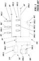
- FIG. 1 In the attached Fig. 1 are illustrated examples of general configurations for existing pneumatic conveying systems 101 used within the waste collection and managing field.
- waste is collected in various areas, such as residential, office or hospital areas.
- the systems 101 include main transport piping 104 that at least in larger systems has pipe branchings for directly connecting to material or, in this case, waste inlet points 102.1, 102.2, 102.3, or for sectioning the main piping 104 in several pipe branches 104.1, 104.2, 104.3. Waste is thus transported in the pipe branches 104.1, 104.2, 104.3 and then in the transport piping 104.
- a waste system 101 is illustrated that may either be a stationary type system SS where waste is transported to a collection central or terminal 105.1 by means of vacuum generated at said station or a mobile type system MS where waste is transported to a waste truck 105.2 by vacuum generated onboard the truck.
- the collection central 105.1 of the stationary type system SS may be any conventional terminal known to the art. It has a vacuum source 106.1, such as one or several strong exhausters, filter equipment, silencers, a compactor and/or separator and a storage capacity in the form of one or several containers or tanks for the collected and normally compacted waste.
- vacuum is communicated to the transport piping 104 through a docking point for a suction tube of a vacuum vehicle 105.2.
- the vacuum vehicle 105.2 may be any type of conventional mobile collection unit including a conventional vacuum truck normally having its own onboard vacuum source 106.2 for applying primary or secondary vacuum air flow and waste separating, compacting and storing equipment.
- the mentioned collection central equipment and vacuum vehicle equipment may be of any standard type used for such systems and will therefore not be specifically described or illustrated in detail herein. Alternatively combinations of such systems may be used (examples thereof are disclosed in document WO 2009/022964 A1 .
- Waste is emptied from the waste inlet points 102.1, 102.2, 102.3 that may be in the form of waste chutes WC extending through multi-story buildings, free-standing waste inserts WI and/or waste tanks WT. From said waste inlet points 102.1, 102.2, 102.3 the emptied waste is conveyed to the collection central 105.1 or waste truck 105.2, respectively.
- the waste chutes WC normally comprise a waste gravity chute of which only the lower part is partially illustrated here and which may have an optional number of waste insertion openings IO (only one indicated).
- Waste inlet points 102.2 being provided in the form of free standing waste inserts WI are normally positioned outdoors, above ground, and provided with at least one insertion opening (not specifically illustrated or denoted) where waste or litter may be introduced.
- Waste chutes WC as well as waste inserts WI are preferably provided at appropriate positions directly above a transport pipe branch 104.1, 104.2 of the vacuum conveying system 101 to allow for a gravity feed of waste into the respective transport pipe or branch.
- an emptying operation is normally initiated by applying vacuum to the main transport piping and by activating the main piping 104 or, in the applicable case, a selected pipe branch 104.1, 104.2, 104.3.
- the activation is performed by opening an air inlet valve AV for the system or for the selected branch.
- the air intake is normally directly associated with the waste tank and has not been specifically indicated in the drawing figure.
- sectioning valves SV may to some degree improve waste transport efficiency and overall waste transport economy of the system 101 and its piping 104. This is due to the fact that such sectioning valves close off the volume of the otherwise open but inactive branches so that the system will not require high air velocity and thus overcapacity of the vacuum producing machines. In systems including sectioning valves the activation of a branch may require the opening of both the respective sectioning and air inlet valves.
- the waste inlet points 102.1, 102.2, 102.3 are each associated with an openable and closable discharge valve 103.1, 103.2, 103.3 so that when opened the valve opens, communication between the inlet points 102.1, 102.2, 102.3 and the relevant transport pipe branch 104.1, 104.2, 104.3 for discharging waste to the transport piping 104 and to the relevant waste truck 105.2 or collection central 105.1.
- the discharge valves 103.1, 103.2, 103.3 block an outlet from the inlet points 102.1, 102.2, 102.3 to provide a seal between the same and the system transport piping 104.
- Waste that has been inserted into the waste inlet points 102.1, 102.2, 102.3 will be discharged therefrom in a controlled or preset sequence during an active phase of the system 101. Specifically, each waste inlet point 102.1, 102.2, 102.3 will be emptied into the designated transport pipe branch 104.1, 104.2, 104.3 when the branch is activated and the associated discharge valve 103.1, 103.2, 103.3 is opened.
- the vacuum waste collection system 101 further comprises a control system 115 (only indicated for the stationary type system SS) for controlling emptying and transport of waste in the conveying system.
- the control system 115 is generally configured to control emptying of waste from the waste inlet points 102.1, 102.2, 102.3 into the system transport piping 104 as well as the suction transport of waste from different branches 104.1, 104.2, 104.3 of the transport piping 104 to the collection central 105.1 or to the waste truck 105.2. This is done by controlling discharge valves, air inlet valves, sectioning valves and vacuum application to the system according to accepted control technology.
- the invention is not concerned with the specific design of discharge valves, air inlets, air inlet valves and/or sectioning valves, which are all well known in the art and may be of any conventional type used in vacuum waste collection systems.
- the present technology attempts to overcome the shortcomings and problems associated with the conventional use of static and predefined emptying control parameters.
- a new approach for controlling the emptying operation is proposed.
- predefined operation times are replaced or supplemented by using a dynamic model for valve open decisions based on remote sensor feedback.
- This inventive concept enables practical and efficient use of the system in a safe and energy efficient way.
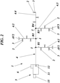
- FIG. 2 shows a schematical pneumatic waste conveying system 1 of the stationary type, as generally described above
- Fig. 3 shows a schematic flow diagram of a sequence of a method of controlling operation of the pneumatic conveying system 1.
- FIG. 2 An exemplifying implementation of the present technology in a pneumatic conveying system 1 is illustrated in Fig. 2 .
- This system like the above described existing system 101, includes the vacuum source 6 for generating transport air flow in an active state thereof, a main transport piping 4 and multiple material inlet points 2 being provided in system branches B1, B2, B3, B4 of the main transport piping 4.
- the material inlet points 2 communicate with the transport piping 4 of the conveying system 1 through associated discharge valves 3 controlling an emptying operation of associated material inlet points 2.
- the four branches B1, B2, B3, B4 are branched off from the main piping 4 via intersections I and are activated when the vacuum source 6 of the collection central 5 operates and its generated vacuum is communicated to the main piping 4, such as by opening a main vacuum valve 9 (see Fig. 5 ).
- the branches B1, B2, B3 are in this embodiment of the system (without sectioning valves) individually activated by opening the associated air inlet valves AV1-AV3.
- one or more branches may lack the common air inlet valve, as is exemplified by branch B4 in Fig. 2 . In such a case the inlet for transport air is associated with the waste inlet points or with their respective discharge valves 3, in a manner that is not specifically illustrated.
- waste is emptied from successive waste inlet points 2 therein and is discharged into the activated branch B1, B2, B3, B4 by the opening of associated discharge valves 3.
- opening a discharge valve 3 waste from the associated waste inlet point 2 is discharged into vacuum air flow in the activated branch B1, B2, B3 or B4.
- the waste is then transported by said vacuum air flow through said branch and the main piping 4 towards the collection central 5 that serves to collect the pneumatically transported or conveyed material.
- the branch is deactivated by closing the corresponding air inlet valve AV1-AV3.
- the emptying sequence of the individual waste inlet points 2 of the branches B1, B2, B3 or B4 and the activation sequence of individual branches B1, B2, B3 or B4 are normally controlled by a computer implemented emptying control system 15.
- Such overall control systems may determine the order of emptying individual branches, waste inlet points or groups thereof and other related timed process operations, such as pre-suction times, intermediate times and transport times.
- Such overall emptying and transport sequence control is based on one or several parameters. The parameters may vary from being only the fill level at the waste inlet points or the waste inlet point distances from the collection central, to being a complex combination of system layout, system specification and system capacity or occupation.
- the exemplifying pneumatic conveying system 1 of the present technology is equipped with later described sensors 11, 12 that are provided for sensing material transport conditions of the system 1.
- the sensors 11, 12 are configured to continuously sense pressure and air speed, respectively, during all active phases of the conveying system 1, i.e. when the vacuum source 6 is active and, in applicable cases, when the main vacuum valve 9 is open.
- the sensors 11, 12 are provided at one or more remote locations with regard to the material inlet points 2 of the system and are arranged in communication with the transport piping 4 for sensing the system transport conditions.
- sensors 11, 12 are positioned at one common location remote from the material or waste inlet points 2.
- the sensors may be positioned in or adjacent the collection central 5 to remotely detect the prevailing material transport conditions of the system 1.
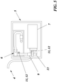
- Fig. 5 are shown two examples of alternative central positions for the sensors 11, 12 in or at the collection central 5.
- the sensors 11, 12 may thus be positioned to sense material transport conditions either in the main piping 4, immediately upstream of the collection central 5 or directly upstream of the vacuum source 6, in piping 13 connecting the vacuum source 6 and a collection tank 7.
- Such a central positioning of the sensors is most cost effective by reducing the number of required sensors to a minimum.
- it may also be considered to position the material transport condition sensors at other locations, such as at or preferably immediately downstream of the branch intersections I.
- a pressure sensor 11 for sensing the system pressure during inlet point emptying operations and air speed sensor 12 for sensing air speed through the system during inlet point emptying operations.
- other appropriate means may be utilized for sensing and determining system pressure and air speed.
- An example thereof is to continuously measure operational parameters of the vacuum source 6, such as load and RPM of an exhauster, and to calculate system pressure and air speed values therefrom.
- the sensors 11, 12 sense pressure and air speed in the branch that has been activated by opening the associated air inlet/air inlet valve AV1-AV3 and, in applicable cases, a respective sequencing valve. For each material inlet point 2 emptying operation, the material transport conditions of the activated system 1 or of an activated branch of the system 1 are thus remotely sensed by the sensors 11, 12.
- a basic idea is to suggest a method of controlling operation of a pneumatic conveying system 1 as described in connection with Fig. 2 .
- the method will here be described for a system comprising multiple branches, but is in embodiments not according to the invention likewise applicable to single branch systems.
- the selected branch will be activated, e.g. by opening an associated air inlet/air inlet valve AV1-AV3 in step S4.
- sensing of the pressure and air speed values of the system 1 is started. Said sensing is continuously performed by the sensors 11, 12 in step S3, at least during the full extent of each system emptying operation, to determine existing system material transport conditions.
- sensing of the material transport conditions is preferably performed at one or more remote locations with regard to the material inlet points 2 of the system 1.
- the selected system branch is activated so that transport conditions may be determined for the system main piping 4 and the selected system branch.
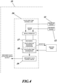
- the sensed pressure and air speed values are fed to and processed by a control circuit 16 illustrated in the schematic block diagram of Fig. 4 .
- the control circuit includes means 17 for processing feedback from the transport condition sensors 11, 12 to evaluate the transport conditions in the system main piping 4 and the selected system branch.
- step S6 the result (OK or NOT OK) of this evaluation is output to a clock or other process timer of the overall control system 15 controlling the overall emptying sequence of the system 1 based on optional system parameters. In a situation where the sensed pressure and air speed values are not within limits, this indicates that acceptable transport conditions are not prevailing in the system 1. As a result, in said step S6, a signal is output from the control circuit 17 pausing the process timer of the overall control system 15.
- a valve open time determining means 18 of the processing means 17 in step S7 determines a valve open time for the discharge valve 3 of the first material inlet point 2 of the selected branch B1-B4.
- the emptying of the first material inlet point 2 of the branch is then performed in steps S8 and S9 by opening and again closing the discharge valve 3.
- step S10 The overall system emptying operation then continues in step S10 by determining a valve open time for each material inlet point 2 of the selected branch. Pressure and air speed are then sensed in each remaining branch B1-B4 of the system 1 and valve open times for the material inlet point 2 discharge valves 3 of each branch are likewise determined based on the processing of feedback from pressure and air speed sensors 11, 12, as described.
- each branch B1-B4 of the system 1 By sensing local pressure and air speed values for the several material inlet points 2 by means of sensors 11, 12 positioned at one common location remote from the material inlet points 2 a very cost efficient system is obtained.
- the emptying process is performed by activating each branch B1-B4 of the system 1 by opening an associated air inlet/air inlet valve AV1-AV3 to enable air flow through said branch.
- a valve open time for the first material inlet point 2 discharge valve 3 of the branch is then determined based on the processing of feedback from the material transport condition sensors.
- Valve open times for successive material inlet point discharge valves of said branch and then of other activated branches are determined based on the processing of feedback from the material transport condition sensors.
- Characteristic of the suggested emptying process is the obtained dynamic time and frequency with respect to open decisions for material inlet point discharge valves.
- valve open time is defined as the discharge valve opening and closing time and thereby the period that the respective discharge valve is open.
- the dynamics are adapted to keep optimal material loading ratio, by speeding up the process when the loading ratio is low and slowing down the process when there is a risk for overload.
- the process uses remote pressure/air speed feedback so that one set of sensors can be used to control multiple material inlet point discharge valves of several system branches. This means that the vacuum waste collection system can be operated in a very energy-efficient manner.
- a control circuit 16 is preferably integrated in the overall control system 15 of the pneumatic conveying system 1.
- the control circuit 16 is configured to determine material inlet point 2 discharge valve 3 open times in dependence of the sensed system transport conditions and more specifically also to determine the frequency of successive material inlet point discharge valve open times based on the sensed system transport conditions and thus on the system material load.
- Feedback from the material transport condition sensors 11, 12, i.e. the remotely sensed pressure and air speed values, is continuously sent to the control circuit 16. Via a signal interface in the control circuit 16 the feedback is received by means 17 for processing feedback from the transport condition sensors, thereby performing an evaluation of the material transport conditions based on the transport condition sensor feedback.
- the processing means 17 further includes means 18 for determining a valve open time for each selected material inlet point 2 discharge valve 3 based on the output from the feedback processing means 17.
- valve open time determining means 18 determine valve open times for the material inlet point 2 discharge valves 3 of the active branch B1, B2, B3, B4 of the system 1. Calculated valve open time values are output to a discharge valve control means 19 for controlling valve open time of the selected material inlet point discharge valves. In other words, from the valve control means 19 is output discharge valve activating signals in dependence upon determined valve open times. Opening and closing of discharge valves 3 of selected material inlet points 2 is performed when the sensed values are within predetermined limits indicating that acceptable system transport conditions exist.
- the overall control system 15 normally selects the branch/discharge valve emptying sequences and thus sends a signal controlling the discharge valve to be activated by the discharge valve open time determining means 18 that frees the transfer of a corresponding activation signal to the selected discharge valve 3 when the sensed values are within predetermined limits.
- the discharge valve open time determining means 18 sends a signal pausing a sequence clock/sequence timer of the overall control system 15 when the sensed values are outside predetermined limits. This will halt the emptying sequence until the transport conditions are again acceptable. It will also influence the discharge valve closing time and thus the normally static (for such conventional overall control systems) period during which a discharge valve remains open.
Landscapes
- Engineering & Computer Science (AREA)
- Mechanical Engineering (AREA)
- Air Transport Of Granular Materials (AREA)
- Refuse Collection And Transfer (AREA)
Claims (7)
- Verfahren zum Steuern des Betriebs eines pneumatischen Fördersystems (1), das eine Quelle (6) zum Erzeugen (S1), in einem aktiven Zustand davon, eines Materialtransportdrucks in dem System, eine Transportleitung (4) und mehrere Materialeinlasspunkte (2) aufweist, die in jedem einer Anzahl von Zweigen (B1, B2, B3, B4) der Transportleitung vorgesehen sind und mit dem System über zugehörige Auslassventile (3) in Verbindung stehen, die einen Entleerungsvorgang zugehöriger Materialeinlasspunkte steuern, wobei ein Transportluftstrom in den Zweigen durch Öffnen (S4) zugehöriger Lufteinlassventile/Lufteinlässe (AV1-AV3) ermöglicht wird und wobei Materialtransportbedingungen des Systems für jeden einer Anzahl von Materialeinlasspunkt-Entleerungsvorgängen erfasst werden (S3), gekennzeichnet durch:- Erfassen der Materialtransportbedingungen in jeder der Anzahl von Zweigen (B1, B2, B3, B4) des Systems (1) während der Einlasspunkt-Entleerungsvorgänge mit Hilfe von Druck- und Luftgeschwindigkeitssensoren (11, 12) des Systems an einem oder mehreren in Bezug auf die Materialeinlasspunkte entfernten Orten; und- Bestimmen (S7), für jeden der Anzahl von Materialeinlasspunkt-Entleerungsvorgängen, einer Ventilöffnungszeit für das Auslassventil der Materialeinlasspunkte (2) der Zweige, basierend auf einer Verarbeitung (S5, S6) von erfassten Druck-und Luftgeschwindigkeitswerten von den Druck- und Luftgeschwindigkeitssensoren (11, 12) des Systems.
- Verfahren nach Anspruch 1, dadurch gekennzeichnet, dass Druck und Luftgeschwindigkeit in jedem der Anzahl von Zweigen (B1, B2, B3, B4) des Systems (1) erfasst werden und dass erfasste Druck- und Luftgeschwindigkeitswerte einer Steuerschaltung (16) mit Mitteln (17) zum Verarbeiten erfasster Druck- und Luftgeschwindigkeitswerte von den Druck- und Luftgeschwindigkeitssensoren (11, 12) zugeführt und von dieser verarbeitet werden (S5), um die Transportbedingungen in den Systemzweigen zu bewerten.
- Verfahren nach Anspruch 1 oder 2, dadurch gekennzeichnet, dass lokale Druck- und Luftgeschwindigkeitswerte für mehrere Materialeinlasspunkte (2) mittels Druck- und Luftgeschwindigkeitssensoren (11, 12) erfasst werden, die an einer gemeinsamen, von den Materialeinlasspunkten (2) entfernten Stelle angeordnet sind, vorzugsweise in oder neben einer Sammelzentrale (5) zum Sammeln von pneumatisch transportiertem Material.
- Verfahren nach Anspruch 2 oder 3, dadurch gekennzeichnet, dass eine Ventilöffnungszeit für das Auslassventil (3) des ersten Materialeinlasspunkts (2) jeder der Anzahl von Zweigen (B1, B2, B3, B4) des Systems (1) auf der Grundlage der Verarbeitung von erfassten Druck- und Luftgeschwindigkeitswerten von den Druck- und Luftgeschwindigkeitssensoren (11, 12) bestimmt wird.
- Verfahren nach Anspruch 4, dadurch gekennzeichnet, dass dann eine Ventilöffnungszeit für aufeinanderfolgende Materialeinlasspunkt(2)-Auslassventile (3) jeder der Anzahl von Zweigen (B1, B2, B3, B4) des Systems (1) auf der Grundlage der Verarbeitung der erfassten Druck-und Luftgeschwindigkeitswerte von den Druck- und Luftgeschwindigkeitssensoren (11, 12) bestimmt wird.
- Pneumatisches Fördersystem (1), das eine Quelle (6) zum Erzeugen eines Transportluftstroms durch Öffnen von Lufteinlassventilen/Lufteinlässen (AV1-AV3) des Fördersystems (1) in einem aktiven Zustand davon, eine Transportrohrleitung (4) und mehrere Materialeinlasspunkten (2) aufweist, die in jeder einer Anzahl von Zweigen (B1, B2, B3, B4) der Transportleitung (4) vorgesehen sind und die mit dem Fördersystem (1) über zugehörige Auslassventile (3) des Fördersystems (1) in Verbindung stehen, wobei die Auslassventile (3) einen Entleerungsvorgang der zugehörigen Materialeinlasspunkte (2) steuern, wobei Systemzustandssensoren (11, 12) vorgesehen und in Verbindung mit der Transportleitung angeordnet sind, um Materialtransportzustände des Systems zu erfassen, dadurch gekennzeichnet, dass sie umfassen:- einen Drucksensor (11) zum Erfassen des Systemdrucks während der Entleerungsvorgänge an den Einlasspunkten und einen Luftgeschwindigkeitssensor (12) zum Erfassen der Luftgeschwindigkeit durch das System während der Entleerungsvorgänge an den Einlasspunkten, die an einer oder mehreren in Bezug auf die Materialeinlasspunkte entfernten Stellen vorgesehen sind;- Mittel (17) zum Verarbeiten der von den Druck- und Luftgeschwindigkeitssensoren erfassten Druck- und Luftgeschwindigkeitswerte;- Mittel (18) zum Bestimmen einer Ventilöffnungszeit für Materialeinlasspunkt(2)-Auslassventile (3) der Transportleitung auf der Grundlage der Ausgabe aus dem Verarbeitungsmittel (17); und- Auslassventil-Steuermittel (19) zur Ausgabe von Auslassventil-Aktivierungssignalen in Abhängigkeit von bestimmten Ventilöffnungszeiten.
- Pneumatisches Fördersystem (1) nach Anspruch 6, dadurch gekennzeichnet, dass die Druck- und Luftgeschwindigkeitssensoren (11, 12) an einer gemeinsamen, von den Materialeinlasspunkten (2) entfernten Stelle angeordnet sind, vorzugsweise in oder neben einer Sammelzentrale (5) zum Sammeln von pneumatisch transportiertem Material.
Applications Claiming Priority (1)
| Application Number | Priority Date | Filing Date | Title |
|---|---|---|---|
| PCT/EP2012/058158 WO2013164030A1 (en) | 2012-05-03 | 2012-05-03 | Method of controlling operation of a pneumatic conveying system |
Publications (2)
| Publication Number | Publication Date |
|---|---|
| EP2844589A1 EP2844589A1 (de) | 2015-03-11 |
| EP2844589B1 true EP2844589B1 (de) | 2022-03-23 |
Family
ID=46027968
Family Applications (1)
| Application Number | Title | Priority Date | Filing Date |
|---|---|---|---|
| EP12718989.2A Active EP2844589B1 (de) | 2012-05-03 | 2012-05-03 | Verfahren zur steuerung des betriebs eines pneumatischen fördersystems |
Country Status (11)
| Country | Link |
|---|---|
| US (1) | US9302849B2 (de) |
| EP (1) | EP2844589B1 (de) |
| KR (1) | KR101938153B1 (de) |
| CN (1) | CN104271471B (de) |
| AU (1) | AU2012378941B2 (de) |
| BR (1) | BR112014027421A2 (de) |
| CA (1) | CA2872072C (de) |
| DK (1) | DK2844589T3 (de) |
| ES (1) | ES2916202T3 (de) |
| SG (1) | SG11201406351XA (de) |
| WO (1) | WO2013164030A1 (de) |
Families Citing this family (16)
| Publication number | Priority date | Publication date | Assignee | Title |
|---|---|---|---|---|
| FI122103B (fi) * | 2010-03-12 | 2011-08-31 | Maricap Oy | Menetelmä ja laitteisto pneumaattisessa materiaalinsiirtojärjestelmässä ja jätteensiirtojärjestelmä |
| FI125741B (fi) * | 2012-07-02 | 2016-01-29 | Maricap Oy | Menetelmä ja laitteisto materiaalin käsittelemiseksi pneumaattisessa materiaalinkäsittelyjärjestelmässä |
| JP6624934B2 (ja) * | 2013-03-05 | 2019-12-25 | マリキャップ オーワイ | 空気圧式物質ハンドリング方法及び機構、並びに廃棄物コンテナー/分離装置 |
| US20160096693A1 (en) * | 2013-03-29 | 2016-04-07 | Matsui Mfg. Co., Ltd. | Material conveyance device and material conveyance method |
| FI125194B (fi) * | 2013-07-30 | 2015-06-30 | Maricap Oy | Menetelmä ja laitteisto jätemateriaalin syöttämiseksi ja käsittelemiseksi |
| CA2904756C (en) * | 2014-11-04 | 2020-01-07 | Cnh Industrial Canada, Ltd. | Independently controlled meter rollers and air conveyance components system and method |
| CN108338404B (zh) * | 2018-04-19 | 2024-07-05 | 南京至诚信息科技有限公司 | 一种风力输送易碎物料自适应控制系统 |
| CN108438911B (zh) * | 2018-04-19 | 2023-11-21 | 江苏高创风电设备有限公司 | 一种补风压力窜级调节系统 |
| CN108433174B (zh) * | 2018-04-19 | 2023-11-21 | 江苏高创风电设备有限公司 | 一种堵管报警及自适应系统 |
| US11999577B2 (en) | 2019-11-18 | 2024-06-04 | George Archambault | Methods and systems for managing airflow in conduits and pneumatic tubes |
| US11565892B2 (en) | 2020-07-08 | 2023-01-31 | Trans-Vac Systems LLC | Methods and systems for operation of a vacuum transport system |
| CN112520420A (zh) * | 2020-12-22 | 2021-03-19 | 上海琮祥机械设备有限公司 | 出料装置及试管远程输送系统 |
| CN113671875B (zh) * | 2021-08-20 | 2023-05-12 | 中国联合重型燃气轮机技术有限公司 | Igcc和igcc的控制方法 |
| CN113879851B (zh) * | 2021-12-08 | 2022-03-01 | 江苏华丽智能科技股份有限公司 | 一种气力输送颗粒物料的传输控制方法及系统 |
| CN114410887B (zh) * | 2021-12-27 | 2023-03-03 | 钢铁研究总院 | 一种分布式连续喷粉控制方法和系统 |
| US12569952B2 (en) * | 2023-06-30 | 2026-03-10 | Power Flow Unlimited, LLC | Power saving shutoff gate for a pneumatic scrap conveying system |
Family Cites Families (22)
| Publication number | Priority date | Publication date | Assignee | Title |
|---|---|---|---|---|
| US1725782A (en) * | 1925-09-17 | 1929-08-27 | Florez Luis De | Method and apparatus for flow control |
| DE2457943C2 (de) * | 1974-12-07 | 1976-06-16 | Ruhrkohle Ag, 4300 Essen | Dreikammer-Rohraufgeber |
| US4917544A (en) * | 1987-02-11 | 1990-04-17 | Vulcan Materials Company | Methods and apparatus for pneumatically transferring a flowable product |
| US5009551A (en) * | 1988-05-12 | 1991-04-23 | Delaware Investments Corp. | Material handling system and control valve therefor |
| JPH0388621A (ja) * | 1989-08-31 | 1991-04-15 | Ebara Corp | 真空式汚水収集装置及び該装置用真空弁コントローラ |
| US5660198A (en) * | 1995-12-21 | 1997-08-26 | J. C. Carter Company, Inc. | Flow compensated pressure control system |
| AU2002357504A1 (en) * | 2001-12-21 | 2003-07-09 | Mitsubishi Chemical Corporation | Device and method for handling lase-of-polymerization substance, device for extracting liquid from device under reduced pressure, and method of manufacturing lase-of-polymerization substance |
| KR200417420Y1 (ko) | 2006-03-08 | 2006-05-26 | 하천용 | 쓰레기 자동집하시설에서 쓰레기를 원거리로 이송하는 장치 |
| KR100785829B1 (ko) | 2006-06-15 | 2007-12-18 | 주식회사 신성엔지니어링 | 고층 건축물의 쓰레기 회수 설비 |
| SE532831C2 (sv) | 2007-06-11 | 2010-04-20 | Envac Ab | Ett vakuumdrivet avfallsinsamlingssystem och en metod för att tömma en central avfallslagringstank |
| ITVR20070083A1 (it) * | 2007-06-12 | 2008-12-13 | Moretto Spa | Impianto per il trasporto pneumatico a velocita' controllata di materiale granulare e procedimento di controllo della velocita' di convogliamento |
| FI122682B (fi) * | 2007-09-18 | 2012-05-31 | Maricap Oy | Jätteiden siirtojärjestelmä |
| EP2254818A1 (de) | 2008-01-28 | 2010-12-01 | Johann Haberl | Rohrleitungssystem, steuerverfahren dafür und verwendung dafür |
| KR100912180B1 (ko) | 2008-02-12 | 2009-08-14 | 현대건설주식회사 | 쓰레기 투입구의 제어용 이중 공기배관에 의한 압축공기 제어장치 및 그 제어방법 |
| FI124436B (fi) | 2008-03-18 | 2014-08-29 | Maricap Oy | Menetelmä ja laitteisto pneumaattisessa materiaalinsiirtojärjestelmässä |
| KR20100083021A (ko) * | 2009-01-12 | 2010-07-21 | 박동분 | 쓰레기 관로 수송 시스템 |
| WO2011010328A1 (en) | 2009-07-20 | 2011-01-27 | Sitrain S.R.L. | A centralised hospital refuse transport and collection system |
| FI20096026L (fi) | 2009-10-06 | 2011-04-07 | Maricap Oy | Menetelmä ja laitteisto pneumaattisessa materiaalinsiirtojärjestelmässä |
| ES2998033T3 (en) * | 2010-03-04 | 2025-02-18 | Envac Ab | Waste emptying control |
| US8747029B2 (en) * | 2010-05-03 | 2014-06-10 | Mac Equipment, Inc. | Low pressure continuous dense phase convey system using a non-critical air control system |
| CN201980657U (zh) * | 2011-01-25 | 2011-09-21 | 上海市金山区青少年活动中心 | 管道中气体输送垃圾的系统 |
| US10043681B2 (en) * | 2013-07-23 | 2018-08-07 | Taiwan Semiconductor Manufacturing Company, Ltd. | Fluid supply system, wafer processing system, and method of supplying fluid to wafer processing equipment |
-
2012
- 2012-05-03 AU AU2012378941A patent/AU2012378941B2/en active Active
- 2012-05-03 CA CA2872072A patent/CA2872072C/en active Active
- 2012-05-03 SG SG11201406351XA patent/SG11201406351XA/en unknown
- 2012-05-03 BR BR112014027421A patent/BR112014027421A2/pt not_active Application Discontinuation
- 2012-05-03 US US14/391,078 patent/US9302849B2/en active Active
- 2012-05-03 CN CN201280072742.4A patent/CN104271471B/zh active Active
- 2012-05-03 EP EP12718989.2A patent/EP2844589B1/de active Active
- 2012-05-03 DK DK12718989.2T patent/DK2844589T3/da active
- 2012-05-03 KR KR1020147031940A patent/KR101938153B1/ko active Active
- 2012-05-03 ES ES12718989T patent/ES2916202T3/es active Active
- 2012-05-03 WO PCT/EP2012/058158 patent/WO2013164030A1/en not_active Ceased
Also Published As
| Publication number | Publication date |
|---|---|
| DK2844589T3 (da) | 2022-05-30 |
| CN104271471B (zh) | 2016-03-30 |
| AU2012378941A1 (en) | 2014-10-30 |
| KR20150088715A (ko) | 2015-08-03 |
| ES2916202T3 (es) | 2022-06-29 |
| US9302849B2 (en) | 2016-04-05 |
| CN104271471A (zh) | 2015-01-07 |
| CA2872072A1 (en) | 2013-11-07 |
| BR112014027421A2 (pt) | 2017-06-27 |
| SG11201406351XA (en) | 2014-11-27 |
| WO2013164030A1 (en) | 2013-11-07 |
| CA2872072C (en) | 2018-11-27 |
| KR101938153B1 (ko) | 2019-01-14 |
| AU2012378941B2 (en) | 2017-02-02 |
| HK1203916A1 (zh) | 2015-11-06 |
| US20150321843A1 (en) | 2015-11-12 |
| EP2844589A1 (de) | 2015-03-11 |
Similar Documents
| Publication | Publication Date | Title |
|---|---|---|
| US9302849B2 (en) | Method of controlling operation of a pneumatic conveying system | |
| EP2585389B1 (de) | Vakuummüllsammelsystem sowie verfahren zum betrieb eines solchen systems | |
| CN104176506B (zh) | 颗粒材料的气动输送系统以及气动输送系统的控制方法 | |
| EP2542484B1 (de) | Abfallentleerungssteuerung | |
| WO2000046129A1 (en) | Refuse transport system | |
| CN208994430U (zh) | 一种垃圾收集系统的气路结构 | |
| CN101778783A (zh) | 垃圾的受控处理方法 | |
| EP1893509B1 (de) | Verfahren zum betrieb eines abfallsammelbehälters und system zur steuerung von dessen betrieb | |
| KR100884812B1 (ko) | 쓰레기 자동집하시설의 음식물 쓰레기 수거 시스템 | |
| CN103508222A (zh) | 粗管下降、细管下降套管式物料降碎器及物料入仓方法 | |
| CN1747881B (zh) | 用于多个分支垃圾收集系统的自动化下一步传输算法 | |
| HK1203916B (en) | Method of controlling operation of a pneumatic conveying system | |
| KR101071807B1 (ko) | 쓰레기 수거 시스템 | |
| EP1163173B2 (de) | Verfahren und vorrichtung zum entleeren des inhalts eines stauraumes in einem mülltransportsystem | |
| AU2012101507A4 (en) | Waste emptying control | |
| EP2695833B1 (de) | Verfahren zum pneumatischen Transport von Müll | |
| CN206838749U (zh) | 一种撬装式餐厨垃圾预处理车厢 | |
| CN206692457U (zh) | 一种撬装式餐厨垃圾油水分离处理车厢 | |
| CN219474766U (zh) | 一种易拉罐废料定量称重器 | |
| JPH063399B2 (ja) | ごみ計量装置 | |
| CN105129435A (zh) | 智能调节分步输灰的方法 | |
| HK1174888B (en) | Waste emptying control | |
| HK1086240B (en) | Automated next-hop algorithm for a multi-branch refuse collection system |
Legal Events
| Date | Code | Title | Description |
|---|---|---|---|
| PUAI | Public reference made under article 153(3) epc to a published international application that has entered the european phase |
Free format text: ORIGINAL CODE: 0009012 |
|
| 17P | Request for examination filed |
Effective date: 20141203 |
|
| AK | Designated contracting states |
Kind code of ref document: A1 Designated state(s): AL AT BE BG CH CY CZ DE DK EE ES FI FR GB GR HR HU IE IS IT LI LT LU LV MC MK MT NL NO PL PT RO RS SE SI SK SM TR |
|
| AX | Request for extension of the european patent |
Extension state: BA ME |
|
| RIN1 | Information on inventor provided before grant (corrected) |
Inventor name: FORESTIER, NIKLAS MATTIAS Inventor name: ALFROST, MARTIN |
|
| RAP3 | Party data changed (applicant data changed or rights of an application transferred) |
Owner name: ENVAC AB |
|
| DAX | Request for extension of the european patent (deleted) | ||
| STAA | Information on the status of an ep patent application or granted ep patent |
Free format text: STATUS: EXAMINATION IS IN PROGRESS |
|
| 17Q | First examination report despatched |
Effective date: 20180820 |
|
| RAP3 | Party data changed (applicant data changed or rights of an application transferred) |
Owner name: ENVAC AB |
|
| GRAP | Despatch of communication of intention to grant a patent |
Free format text: ORIGINAL CODE: EPIDOSNIGR1 |
|
| STAA | Information on the status of an ep patent application or granted ep patent |
Free format text: STATUS: GRANT OF PATENT IS INTENDED |
|
| GRAJ | Information related to disapproval of communication of intention to grant by the applicant or resumption of examination proceedings by the epo deleted |
Free format text: ORIGINAL CODE: EPIDOSDIGR1 |
|
| STAA | Information on the status of an ep patent application or granted ep patent |
Free format text: STATUS: EXAMINATION IS IN PROGRESS |
|
| INTG | Intention to grant announced |
Effective date: 20211119 |
|
| INTC | Intention to grant announced (deleted) | ||
| GRAP | Despatch of communication of intention to grant a patent |
Free format text: ORIGINAL CODE: EPIDOSNIGR1 |
|
| STAA | Information on the status of an ep patent application or granted ep patent |
Free format text: STATUS: GRANT OF PATENT IS INTENDED |
|
| GRAS | Grant fee paid |
Free format text: ORIGINAL CODE: EPIDOSNIGR3 |
|
| INTG | Intention to grant announced |
Effective date: 20220118 |
|
| GRAA | (expected) grant |
Free format text: ORIGINAL CODE: 0009210 |
|
| STAA | Information on the status of an ep patent application or granted ep patent |
Free format text: STATUS: THE PATENT HAS BEEN GRANTED |
|
| AK | Designated contracting states |
Kind code of ref document: B1 Designated state(s): AL AT BE BG CH CY CZ DE DK EE ES FI FR GB GR HR HU IE IS IT LI LT LU LV MC MK MT NL NO PL PT RO RS SE SI SK SM TR |
|
| REG | Reference to a national code |
Ref country code: GB Ref legal event code: FG4D |
|
| REG | Reference to a national code |
Ref country code: CH Ref legal event code: EP |
|
| REG | Reference to a national code |
Ref country code: DE Ref legal event code: R096 Ref document number: 602012077894 Country of ref document: DE |
|
| REG | Reference to a national code |
Ref country code: IE Ref legal event code: FG4D |
|
| REG | Reference to a national code |
Ref country code: AT Ref legal event code: REF Ref document number: 1477304 Country of ref document: AT Kind code of ref document: T Effective date: 20220415 |
|
| REG | Reference to a national code |
Ref country code: DK Ref legal event code: T3 Effective date: 20220523 |
|
| REG | Reference to a national code |
Ref country code: FI Ref legal event code: FGE Ref country code: SE Ref legal event code: TRGR |
|
| REG | Reference to a national code |
Ref country code: ES Ref legal event code: FG2A Ref document number: 2916202 Country of ref document: ES Kind code of ref document: T3 Effective date: 20220629 |
|
| REG | Reference to a national code |
Ref country code: LT Ref legal event code: MG9D |
|
| REG | Reference to a national code |
Ref country code: NO Ref legal event code: T2 Effective date: 20220323 |
|
| REG | Reference to a national code |
Ref country code: NL Ref legal event code: MP Effective date: 20220323 |
|
| PG25 | Lapsed in a contracting state [announced via postgrant information from national office to epo] |
Ref country code: RS Free format text: LAPSE BECAUSE OF FAILURE TO SUBMIT A TRANSLATION OF THE DESCRIPTION OR TO PAY THE FEE WITHIN THE PRESCRIBED TIME-LIMIT Effective date: 20220323 Ref country code: LT Free format text: LAPSE BECAUSE OF FAILURE TO SUBMIT A TRANSLATION OF THE DESCRIPTION OR TO PAY THE FEE WITHIN THE PRESCRIBED TIME-LIMIT Effective date: 20220323 Ref country code: HR Free format text: LAPSE BECAUSE OF FAILURE TO SUBMIT A TRANSLATION OF THE DESCRIPTION OR TO PAY THE FEE WITHIN THE PRESCRIBED TIME-LIMIT Effective date: 20220323 Ref country code: BG Free format text: LAPSE BECAUSE OF FAILURE TO SUBMIT A TRANSLATION OF THE DESCRIPTION OR TO PAY THE FEE WITHIN THE PRESCRIBED TIME-LIMIT Effective date: 20220623 |
|
| REG | Reference to a national code |
Ref country code: AT Ref legal event code: MK05 Ref document number: 1477304 Country of ref document: AT Kind code of ref document: T Effective date: 20220323 |
|
| PG25 | Lapsed in a contracting state [announced via postgrant information from national office to epo] |
Ref country code: LV Free format text: LAPSE BECAUSE OF FAILURE TO SUBMIT A TRANSLATION OF THE DESCRIPTION OR TO PAY THE FEE WITHIN THE PRESCRIBED TIME-LIMIT Effective date: 20220323 Ref country code: GR Free format text: LAPSE BECAUSE OF FAILURE TO SUBMIT A TRANSLATION OF THE DESCRIPTION OR TO PAY THE FEE WITHIN THE PRESCRIBED TIME-LIMIT Effective date: 20220624 |
|
| PG25 | Lapsed in a contracting state [announced via postgrant information from national office to epo] |
Ref country code: NL Free format text: LAPSE BECAUSE OF FAILURE TO SUBMIT A TRANSLATION OF THE DESCRIPTION OR TO PAY THE FEE WITHIN THE PRESCRIBED TIME-LIMIT Effective date: 20220323 |
|
| PG25 | Lapsed in a contracting state [announced via postgrant information from national office to epo] |
Ref country code: SM Free format text: LAPSE BECAUSE OF FAILURE TO SUBMIT A TRANSLATION OF THE DESCRIPTION OR TO PAY THE FEE WITHIN THE PRESCRIBED TIME-LIMIT Effective date: 20220323 Ref country code: SK Free format text: LAPSE BECAUSE OF FAILURE TO SUBMIT A TRANSLATION OF THE DESCRIPTION OR TO PAY THE FEE WITHIN THE PRESCRIBED TIME-LIMIT Effective date: 20220323 Ref country code: RO Free format text: LAPSE BECAUSE OF FAILURE TO SUBMIT A TRANSLATION OF THE DESCRIPTION OR TO PAY THE FEE WITHIN THE PRESCRIBED TIME-LIMIT Effective date: 20220323 Ref country code: PT Free format text: LAPSE BECAUSE OF FAILURE TO SUBMIT A TRANSLATION OF THE DESCRIPTION OR TO PAY THE FEE WITHIN THE PRESCRIBED TIME-LIMIT Effective date: 20220725 Ref country code: EE Free format text: LAPSE BECAUSE OF FAILURE TO SUBMIT A TRANSLATION OF THE DESCRIPTION OR TO PAY THE FEE WITHIN THE PRESCRIBED TIME-LIMIT Effective date: 20220323 Ref country code: CZ Free format text: LAPSE BECAUSE OF FAILURE TO SUBMIT A TRANSLATION OF THE DESCRIPTION OR TO PAY THE FEE WITHIN THE PRESCRIBED TIME-LIMIT Effective date: 20220323 Ref country code: AT Free format text: LAPSE BECAUSE OF FAILURE TO SUBMIT A TRANSLATION OF THE DESCRIPTION OR TO PAY THE FEE WITHIN THE PRESCRIBED TIME-LIMIT Effective date: 20220323 |
|
| PG25 | Lapsed in a contracting state [announced via postgrant information from national office to epo] |
Ref country code: PL Free format text: LAPSE BECAUSE OF FAILURE TO SUBMIT A TRANSLATION OF THE DESCRIPTION OR TO PAY THE FEE WITHIN THE PRESCRIBED TIME-LIMIT Effective date: 20220323 Ref country code: IS Free format text: LAPSE BECAUSE OF FAILURE TO SUBMIT A TRANSLATION OF THE DESCRIPTION OR TO PAY THE FEE WITHIN THE PRESCRIBED TIME-LIMIT Effective date: 20220723 Ref country code: AL Free format text: LAPSE BECAUSE OF FAILURE TO SUBMIT A TRANSLATION OF THE DESCRIPTION OR TO PAY THE FEE WITHIN THE PRESCRIBED TIME-LIMIT Effective date: 20220323 |
|
| REG | Reference to a national code |
Ref country code: CH Ref legal event code: PL |
|
| REG | Reference to a national code |
Ref country code: DE Ref legal event code: R097 Ref document number: 602012077894 Country of ref document: DE |
|
| REG | Reference to a national code |
Ref country code: DK Ref legal event code: EBP Effective date: 20220630 |
|
| REG | Reference to a national code |
Ref country code: BE Ref legal event code: MM Effective date: 20220531 |
|
| PLBE | No opposition filed within time limit |
Free format text: ORIGINAL CODE: 0009261 |
|
| STAA | Information on the status of an ep patent application or granted ep patent |
Free format text: STATUS: NO OPPOSITION FILED WITHIN TIME LIMIT |
|
| PG25 | Lapsed in a contracting state [announced via postgrant information from national office to epo] |
Ref country code: MC Free format text: LAPSE BECAUSE OF FAILURE TO SUBMIT A TRANSLATION OF THE DESCRIPTION OR TO PAY THE FEE WITHIN THE PRESCRIBED TIME-LIMIT Effective date: 20220323 Ref country code: LU Free format text: LAPSE BECAUSE OF NON-PAYMENT OF DUE FEES Effective date: 20220503 Ref country code: LI Free format text: LAPSE BECAUSE OF NON-PAYMENT OF DUE FEES Effective date: 20220531 Ref country code: CH Free format text: LAPSE BECAUSE OF NON-PAYMENT OF DUE FEES Effective date: 20220531 |
|
| 26N | No opposition filed |
Effective date: 20230102 |
|
| REG | Reference to a national code |
Ref country code: FR Ref legal event code: PLFP Year of fee payment: 12 |
|
| PG25 | Lapsed in a contracting state [announced via postgrant information from national office to epo] |
Ref country code: IE Free format text: LAPSE BECAUSE OF NON-PAYMENT OF DUE FEES Effective date: 20220503 |
|
| PG25 | Lapsed in a contracting state [announced via postgrant information from national office to epo] |
Ref country code: SI Free format text: LAPSE BECAUSE OF FAILURE TO SUBMIT A TRANSLATION OF THE DESCRIPTION OR TO PAY THE FEE WITHIN THE PRESCRIBED TIME-LIMIT Effective date: 20220323 Ref country code: BE Free format text: LAPSE BECAUSE OF NON-PAYMENT OF DUE FEES Effective date: 20220531 |
|
| PG25 | Lapsed in a contracting state [announced via postgrant information from national office to epo] |
Ref country code: IT Free format text: LAPSE BECAUSE OF FAILURE TO SUBMIT A TRANSLATION OF THE DESCRIPTION OR TO PAY THE FEE WITHIN THE PRESCRIBED TIME-LIMIT Effective date: 20220323 Ref country code: DK Free format text: LAPSE BECAUSE OF NON-PAYMENT OF DUE FEES Effective date: 20220630 |
|
| PG25 | Lapsed in a contracting state [announced via postgrant information from national office to epo] |
Ref country code: HU Free format text: LAPSE BECAUSE OF FAILURE TO SUBMIT A TRANSLATION OF THE DESCRIPTION OR TO PAY THE FEE WITHIN THE PRESCRIBED TIME-LIMIT; INVALID AB INITIO Effective date: 20120503 |
|
| PG25 | Lapsed in a contracting state [announced via postgrant information from national office to epo] |
Ref country code: MK Free format text: LAPSE BECAUSE OF FAILURE TO SUBMIT A TRANSLATION OF THE DESCRIPTION OR TO PAY THE FEE WITHIN THE PRESCRIBED TIME-LIMIT Effective date: 20220323 Ref country code: CY Free format text: LAPSE BECAUSE OF FAILURE TO SUBMIT A TRANSLATION OF THE DESCRIPTION OR TO PAY THE FEE WITHIN THE PRESCRIBED TIME-LIMIT Effective date: 20220323 |
|
| PG25 | Lapsed in a contracting state [announced via postgrant information from national office to epo] |
Ref country code: MT Free format text: LAPSE BECAUSE OF FAILURE TO SUBMIT A TRANSLATION OF THE DESCRIPTION OR TO PAY THE FEE WITHIN THE PRESCRIBED TIME-LIMIT Effective date: 20220323 |
|
| REG | Reference to a national code |
Ref country code: DK Ref legal event code: EGE Effective date: 20241203 |
|
| PG25 | Lapsed in a contracting state [announced via postgrant information from national office to epo] |
Ref country code: DK Free format text: LAPSE BECAUSE OF NON-PAYMENT OF DUE FEES Effective date: 20220630 |
|
| PGRI | Patent reinstated in contracting state [announced from national office to epo] |
Ref country code: DK Effective date: 20241129 |
|
| PG25 | Lapsed in a contracting state [announced via postgrant information from national office to epo] |
Ref country code: DK Free format text: LAPSE BECAUSE OF NON-PAYMENT OF DUE FEES Effective date: 20220630 |
|
| PGRI | Patent reinstated in contracting state [announced from national office to epo] |
Ref country code: DK Effective date: 20241129 |
|
| PGFP | Annual fee paid to national office [announced via postgrant information from national office to epo] |
Ref country code: FI Payment date: 20250414 Year of fee payment: 14 |
|
| PGFP | Annual fee paid to national office [announced via postgrant information from national office to epo] |
Ref country code: DE Payment date: 20250416 Year of fee payment: 14 |
|
| PGFP | Annual fee paid to national office [announced via postgrant information from national office to epo] |
Ref country code: ES Payment date: 20250602 Year of fee payment: 14 |
|
| PGFP | Annual fee paid to national office [announced via postgrant information from national office to epo] |
Ref country code: NO Payment date: 20250416 Year of fee payment: 14 |
|
| PGFP | Annual fee paid to national office [announced via postgrant information from national office to epo] |
Ref country code: FR Payment date: 20250414 Year of fee payment: 14 |
|
| PG25 | Lapsed in a contracting state [announced via postgrant information from national office to epo] |
Ref country code: TR Free format text: LAPSE BECAUSE OF FAILURE TO SUBMIT A TRANSLATION OF THE DESCRIPTION OR TO PAY THE FEE WITHIN THE PRESCRIBED TIME-LIMIT Effective date: 20220323 |
|
| PGFP | Annual fee paid to national office [announced via postgrant information from national office to epo] |
Ref country code: SE Payment date: 20260331 Year of fee payment: 15 |
|
| PGFP | Annual fee paid to national office [announced via postgrant information from national office to epo] |
Ref country code: GB Payment date: 20260317 Year of fee payment: 15 |
|
| PGFP | Annual fee paid to national office [announced via postgrant information from national office to epo] |
Ref country code: DK Payment date: 20260316 Year of fee payment: 15 |