EP2842916B1 - Verfahren und vorrichtung zur herstellung eines rohrs mit einem abschnittsweise von einer kreisform abweichenden profil und kreisförmigen endabschnitten. - Google Patents
Verfahren und vorrichtung zur herstellung eines rohrs mit einem abschnittsweise von einer kreisform abweichenden profil und kreisförmigen endabschnitten. Download PDFInfo
- Publication number
- EP2842916B1 EP2842916B1 EP14181847.6A EP14181847A EP2842916B1 EP 2842916 B1 EP2842916 B1 EP 2842916B1 EP 14181847 A EP14181847 A EP 14181847A EP 2842916 B1 EP2842916 B1 EP 2842916B1
- Authority
- EP
- European Patent Office
- Prior art keywords
- tube
- nip
- profile
- circular
- squeezing rollers
- Prior art date
- Legal status (The legal status is an assumption and is not a legal conclusion. Google has not performed a legal analysis and makes no representation as to the accuracy of the status listed.)
- Not-in-force
Links
- 238000000034 method Methods 0.000 title claims description 41
- 238000004519 manufacturing process Methods 0.000 title claims description 17
- 239000011521 glass Substances 0.000 claims description 93
- 229920003023 plastic Polymers 0.000 claims description 31
- 239000004033 plastic Substances 0.000 claims description 27
- 239000000463 material Substances 0.000 claims description 21
- 230000007704 transition Effects 0.000 claims description 15
- 230000004323 axial length Effects 0.000 claims description 8
- 239000002131 composite material Substances 0.000 claims description 7
- DQEFEBPAPFSJLV-UHFFFAOYSA-N Cellulose propionate Chemical compound CCC(=O)OCC1OC(OC(=O)CC)C(OC(=O)CC)C(OC(=O)CC)C1OC1C(OC(=O)CC)C(OC(=O)CC)C(OC(=O)CC)C(COC(=O)CC)O1 DQEFEBPAPFSJLV-UHFFFAOYSA-N 0.000 claims description 4
- 239000004952 Polyamide Substances 0.000 claims description 4
- 239000004698 Polyethylene Substances 0.000 claims description 4
- 239000004743 Polypropylene Substances 0.000 claims description 4
- 229920006218 cellulose propionate Polymers 0.000 claims description 4
- 229920003229 poly(methyl methacrylate) Polymers 0.000 claims description 4
- 229920002647 polyamide Polymers 0.000 claims description 4
- -1 polyethylene Polymers 0.000 claims description 4
- 229920000573 polyethylene Polymers 0.000 claims description 4
- 239000004926 polymethyl methacrylate Substances 0.000 claims description 4
- 229920001155 polypropylene Polymers 0.000 claims description 4
- PPBRXRYQALVLMV-UHFFFAOYSA-N Styrene Chemical compound C=CC1=CC=CC=C1 PPBRXRYQALVLMV-UHFFFAOYSA-N 0.000 claims description 3
- WSSSPWUEQFSQQG-UHFFFAOYSA-N 4-methyl-1-pentene Chemical compound CC(C)CC=C WSSSPWUEQFSQQG-UHFFFAOYSA-N 0.000 claims description 2
- NLHHRLWOUZZQLW-UHFFFAOYSA-N Acrylonitrile Chemical compound C=CC#N NLHHRLWOUZZQLW-UHFFFAOYSA-N 0.000 claims description 2
- VVQNEPGJFQJSBK-UHFFFAOYSA-N Methyl methacrylate Chemical compound COC(=O)C(C)=C VVQNEPGJFQJSBK-UHFFFAOYSA-N 0.000 claims description 2
- 239000005062 Polybutadiene Substances 0.000 claims description 2
- 125000003118 aryl group Chemical group 0.000 claims description 2
- 229920002857 polybutadiene Polymers 0.000 claims description 2
- 239000004417 polycarbonate Substances 0.000 claims description 2
- 229920000515 polycarbonate Polymers 0.000 claims description 2
- 229920000728 polyester Polymers 0.000 claims description 2
- 239000004800 polyvinyl chloride Substances 0.000 claims description 2
- 125000004122 cyclic group Chemical group 0.000 claims 2
- 229920002223 polystyrene Polymers 0.000 claims 2
- KAKZBPTYRLMSJV-UHFFFAOYSA-N Butadiene Chemical compound C=CC=C KAKZBPTYRLMSJV-UHFFFAOYSA-N 0.000 claims 1
- 244000005700 microbiome Species 0.000 description 15
- 238000006073 displacement reaction Methods 0.000 description 11
- 239000012530 fluid Substances 0.000 description 10
- 238000010438 heat treatment Methods 0.000 description 8
- 239000007788 liquid Substances 0.000 description 8
- 230000001105 regulatory effect Effects 0.000 description 8
- 230000015572 biosynthetic process Effects 0.000 description 6
- 230000008859 change Effects 0.000 description 6
- 238000001816 cooling Methods 0.000 description 6
- 241000195493 Cryptophyta Species 0.000 description 5
- 230000008901 benefit Effects 0.000 description 5
- 230000001965 increasing effect Effects 0.000 description 5
- 238000013519 translation Methods 0.000 description 5
- 244000089486 Phragmites australis subsp australis Species 0.000 description 4
- 238000005516 engineering process Methods 0.000 description 4
- 230000001678 irradiating effect Effects 0.000 description 4
- 230000001360 synchronised effect Effects 0.000 description 4
- 238000007373 indentation Methods 0.000 description 3
- 238000012634 optical imaging Methods 0.000 description 3
- 230000009466 transformation Effects 0.000 description 3
- CURLTUGMZLYLDI-UHFFFAOYSA-N Carbon dioxide Chemical compound O=C=O CURLTUGMZLYLDI-UHFFFAOYSA-N 0.000 description 2
- 238000010586 diagram Methods 0.000 description 2
- 230000000694 effects Effects 0.000 description 2
- 238000012886 linear function Methods 0.000 description 2
- 239000006060 molten glass Substances 0.000 description 2
- 235000015097 nutrients Nutrition 0.000 description 2
- 230000003287 optical effect Effects 0.000 description 2
- 230000008569 process Effects 0.000 description 2
- 238000005096 rolling process Methods 0.000 description 2
- XLYOFNOQVPJJNP-UHFFFAOYSA-N water Substances O XLYOFNOQVPJJNP-UHFFFAOYSA-N 0.000 description 2
- 229910019142 PO4 Inorganic materials 0.000 description 1
- 229920012266 Poly(ether sulfone) PES Polymers 0.000 description 1
- 239000004793 Polystyrene Substances 0.000 description 1
- 230000005791 algae growth Effects 0.000 description 1
- 238000005452 bending Methods 0.000 description 1
- 230000005540 biological transmission Effects 0.000 description 1
- MTAZNLWOLGHBHU-UHFFFAOYSA-N butadiene-styrene rubber Chemical compound C=CC=C.C=CC1=CC=CC=C1 MTAZNLWOLGHBHU-UHFFFAOYSA-N 0.000 description 1
- 229910002092 carbon dioxide Inorganic materials 0.000 description 1
- 239000001569 carbon dioxide Substances 0.000 description 1
- 230000001276 controlling effect Effects 0.000 description 1
- 238000007796 conventional method Methods 0.000 description 1
- 229920001577 copolymer Polymers 0.000 description 1
- 230000008878 coupling Effects 0.000 description 1
- 238000010168 coupling process Methods 0.000 description 1
- 238000005859 coupling reaction Methods 0.000 description 1
- 238000005520 cutting process Methods 0.000 description 1
- 230000006378 damage Effects 0.000 description 1
- 230000003247 decreasing effect Effects 0.000 description 1
- 230000001419 dependent effect Effects 0.000 description 1
- 238000013461 design Methods 0.000 description 1
- 238000003280 down draw process Methods 0.000 description 1
- 239000005292 fiolax Substances 0.000 description 1
- 239000013505 freshwater Substances 0.000 description 1
- 229920000578 graft copolymer Polymers 0.000 description 1
- 230000001939 inductive effect Effects 0.000 description 1
- 238000009434 installation Methods 0.000 description 1
- 238000005304 joining Methods 0.000 description 1
- 238000002372 labelling Methods 0.000 description 1
- 238000010330 laser marking Methods 0.000 description 1
- 230000013011 mating Effects 0.000 description 1
- 239000011159 matrix material Substances 0.000 description 1
- 238000005259 measurement Methods 0.000 description 1
- 229920012128 methyl methacrylate acrylonitrile butadiene styrene Polymers 0.000 description 1
- 238000012986 modification Methods 0.000 description 1
- 230000004048 modification Effects 0.000 description 1
- 238000012544 monitoring process Methods 0.000 description 1
- 239000002105 nanoparticle Substances 0.000 description 1
- 229910052757 nitrogen Inorganic materials 0.000 description 1
- 229910017464 nitrogen compound Inorganic materials 0.000 description 1
- 150000002830 nitrogen compounds Chemical class 0.000 description 1
- 238000013021 overheating Methods 0.000 description 1
- 239000002245 particle Substances 0.000 description 1
- 230000002688 persistence Effects 0.000 description 1
- 238000009512 pharmaceutical packaging Methods 0.000 description 1
- NBIIXXVUZAFLBC-UHFFFAOYSA-K phosphate Chemical compound [O-]P([O-])([O-])=O NBIIXXVUZAFLBC-UHFFFAOYSA-K 0.000 description 1
- 239000010452 phosphate Substances 0.000 description 1
- 238000005498 polishing Methods 0.000 description 1
- 239000004810 polytetrafluoroethylene Substances 0.000 description 1
- 229920001343 polytetrafluoroethylene Polymers 0.000 description 1
- 230000008092 positive effect Effects 0.000 description 1
- 230000002028 premature Effects 0.000 description 1
- 238000002360 preparation method Methods 0.000 description 1
- 230000005855 radiation Effects 0.000 description 1
- 238000002407 reforming Methods 0.000 description 1
- 239000013535 sea water Substances 0.000 description 1
- 239000004065 semiconductor Substances 0.000 description 1
- 238000007493 shaping process Methods 0.000 description 1
- HUAUNKAZQWMVFY-UHFFFAOYSA-M sodium;oxocalcium;hydroxide Chemical compound [OH-].[Na+].[Ca]=O HUAUNKAZQWMVFY-UHFFFAOYSA-M 0.000 description 1
- 238000003860 storage Methods 0.000 description 1
- 229920006132 styrene block copolymer Polymers 0.000 description 1
- 230000002277 temperature effect Effects 0.000 description 1
- 230000036962 time dependent Effects 0.000 description 1
- 239000012780 transparent material Substances 0.000 description 1
- 238000011144 upstream manufacturing Methods 0.000 description 1
Images


Classifications
-
- C—CHEMISTRY; METALLURGY
- C03—GLASS; MINERAL OR SLAG WOOL
- C03B—MANUFACTURE, SHAPING, OR SUPPLEMENTARY PROCESSES
- C03B23/00—Re-forming shaped glass
- C03B23/04—Re-forming tubes or rods
- C03B23/049—Re-forming tubes or rods by pressing
-
- C—CHEMISTRY; METALLURGY
- C03—GLASS; MINERAL OR SLAG WOOL
- C03B—MANUFACTURE, SHAPING, OR SUPPLEMENTARY PROCESSES
- C03B23/00—Re-forming shaped glass
- C03B23/04—Re-forming tubes or rods
- C03B23/055—Re-forming tubes or rods by rolling
-
- B—PERFORMING OPERATIONS; TRANSPORTING
- B29—WORKING OF PLASTICS; WORKING OF SUBSTANCES IN A PLASTIC STATE IN GENERAL
- B29C—SHAPING OR JOINING OF PLASTICS; SHAPING OF MATERIAL IN A PLASTIC STATE, NOT OTHERWISE PROVIDED FOR; AFTER-TREATMENT OF THE SHAPED PRODUCTS, e.g. REPAIRING
- B29C53/00—Shaping by bending, folding, twisting, straightening or flattening; Apparatus therefor
- B29C53/02—Bending or folding
- B29C53/08—Bending or folding of tubes or other profiled members
- B29C53/086—Bending or folding of tubes or other profiled members bending radially, i.e. deformig the cross-section of the tube
-
- C—CHEMISTRY; METALLURGY
- C03—GLASS; MINERAL OR SLAG WOOL
- C03B—MANUFACTURE, SHAPING, OR SUPPLEMENTARY PROCESSES
- C03B23/00—Re-forming shaped glass
- C03B23/04—Re-forming tubes or rods
- C03B23/045—Tools or apparatus specially adapted for re-forming tubes or rods in general, e.g. glass lathes, chucks
-
- C—CHEMISTRY; METALLURGY
- C12—BIOCHEMISTRY; BEER; SPIRITS; WINE; VINEGAR; MICROBIOLOGY; ENZYMOLOGY; MUTATION OR GENETIC ENGINEERING
- C12M—APPARATUS FOR ENZYMOLOGY OR MICROBIOLOGY; APPARATUS FOR CULTURING MICROORGANISMS FOR PRODUCING BIOMASS, FOR GROWING CELLS OR FOR OBTAINING FERMENTATION OR METABOLIC PRODUCTS, i.e. BIOREACTORS OR FERMENTERS
- C12M21/00—Bioreactors or fermenters specially adapted for specific uses
- C12M21/02—Photobioreactors
-
- C—CHEMISTRY; METALLURGY
- C12—BIOCHEMISTRY; BEER; SPIRITS; WINE; VINEGAR; MICROBIOLOGY; ENZYMOLOGY; MUTATION OR GENETIC ENGINEERING
- C12M—APPARATUS FOR ENZYMOLOGY OR MICROBIOLOGY; APPARATUS FOR CULTURING MICROORGANISMS FOR PRODUCING BIOMASS, FOR GROWING CELLS OR FOR OBTAINING FERMENTATION OR METABOLIC PRODUCTS, i.e. BIOREACTORS OR FERMENTERS
- C12M23/00—Constructional details, e.g. recesses, hinges
- C12M23/02—Form or structure of the vessel
- C12M23/06—Tubular
-
- C—CHEMISTRY; METALLURGY
- C12—BIOCHEMISTRY; BEER; SPIRITS; WINE; VINEGAR; MICROBIOLOGY; ENZYMOLOGY; MUTATION OR GENETIC ENGINEERING
- C12M—APPARATUS FOR ENZYMOLOGY OR MICROBIOLOGY; APPARATUS FOR CULTURING MICROORGANISMS FOR PRODUCING BIOMASS, FOR GROWING CELLS OR FOR OBTAINING FERMENTATION OR METABOLIC PRODUCTS, i.e. BIOREACTORS OR FERMENTERS
- C12M23/00—Constructional details, e.g. recesses, hinges
- C12M23/22—Transparent or translucent parts
-
- G—PHYSICS
- G01—MEASURING; TESTING
- G01B—MEASURING LENGTH, THICKNESS OR SIMILAR LINEAR DIMENSIONS; MEASURING ANGLES; MEASURING AREAS; MEASURING IRREGULARITIES OF SURFACES OR CONTOURS
- G01B11/00—Measuring arrangements characterised by the use of optical techniques
- G01B11/02—Measuring arrangements characterised by the use of optical techniques for measuring length, width or thickness
- G01B11/04—Measuring arrangements characterised by the use of optical techniques for measuring length, width or thickness specially adapted for measuring length or width of objects while moving
- G01B11/043—Measuring arrangements characterised by the use of optical techniques for measuring length, width or thickness specially adapted for measuring length or width of objects while moving for measuring length
-
- G—PHYSICS
- G01—MEASURING; TESTING
- G01B—MEASURING LENGTH, THICKNESS OR SIMILAR LINEAR DIMENSIONS; MEASURING ANGLES; MEASURING AREAS; MEASURING IRREGULARITIES OF SURFACES OR CONTOURS
- G01B11/00—Measuring arrangements characterised by the use of optical techniques
- G01B11/08—Measuring arrangements characterised by the use of optical techniques for measuring diameters
- G01B11/12—Measuring arrangements characterised by the use of optical techniques for measuring diameters internal diameters
-
- B—PERFORMING OPERATIONS; TRANSPORTING
- B29—WORKING OF PLASTICS; WORKING OF SUBSTANCES IN A PLASTIC STATE IN GENERAL
- B29K—INDEXING SCHEME ASSOCIATED WITH SUBCLASSES B29B, B29C OR B29D, RELATING TO MOULDING MATERIALS OR TO MATERIALS FOR MOULDS, REINFORCEMENTS, FILLERS OR PREFORMED PARTS, e.g. INSERTS
- B29K2101/00—Use of unspecified macromolecular compounds as moulding material
- B29K2101/12—Thermoplastic materials
-
- B—PERFORMING OPERATIONS; TRANSPORTING
- B29—WORKING OF PLASTICS; WORKING OF SUBSTANCES IN A PLASTIC STATE IN GENERAL
- B29K—INDEXING SCHEME ASSOCIATED WITH SUBCLASSES B29B, B29C OR B29D, RELATING TO MOULDING MATERIALS OR TO MATERIALS FOR MOULDS, REINFORCEMENTS, FILLERS OR PREFORMED PARTS, e.g. INSERTS
- B29K2105/00—Condition, form or state of moulded material or of the material to be shaped
- B29K2105/25—Solid
- B29K2105/253—Preform
- B29K2105/258—Tubular
-
- C—CHEMISTRY; METALLURGY
- C03—GLASS; MINERAL OR SLAG WOOL
- C03B—MANUFACTURE, SHAPING, OR SUPPLEMENTARY PROCESSES
- C03B23/00—Re-forming shaped glass
- C03B23/04—Re-forming tubes or rods
- C03B23/09—Reshaping the ends, e.g. as grooves, threads or mouths
- C03B23/095—Reshaping the ends, e.g. as grooves, threads or mouths by rolling
Definitions
- the present invention relates generally to the production of pipes of a transparent glass, plastic or plastic composite material having a deviating from the circular profile with high precision, for example as an oval tube, and in particular relates to the production of a tube with a sectionally deviating from a circular profile and circular end sections.
- pipes typically have a consistent profile over their entire length.
- glass tubes with a circular profile are known from the prior art for applications as pharmaceutical packaging, for lighting purposes or for solar thermal energy.
- Oval glass tubes having a different from the circular profile are sold by the applicant under the brands Conturax ® and Conturax Pro ®. The profile is constant over the entire length of the glass tubes.
- Oval tubes are also used for fluorescent lamps (cf. JP 61224257 A2 ).
- Tubes with a profile deviating from the circular shape of plastic or plastic composite materials are used, for example, in underfloor heating systems.
- DE 545449 A discloses an apparatus for forming glass tubes into glass tubes having a non-circular profile, the glass tubes being conveyed through a nip in the heated state.
- DE 1007962 A discloses a corresponding method for forming glass tubes into thin insulating tapes or insulating layers.
- DE 102006015223 B3 The applicant discloses a method and an apparatus for producing a glass tube with a profile deviating from the circular shape.
- the starting glass tube with the output profile (preform) first passes through a hot zone to form a drawing bulb and then one of a pair of rollers formed nip in which the drawing bulb is formed into a glass tube with a different profile.
- the aforementioned glass tubes always have a constant profile over their entire length.
- JP 2006315919 A and JP 2006004660 A2 disclose glass tubes for cold cathode fluorescent lamps (CCFL) with sections with a non-circular profile that alternate with sections with a circular profile. For this purpose, a glass tube in sections in a hot, plastically deformable state, partially also bent. The glass tubes are melted at the ends, but not formed open and thus can not be connected to connection means or adjacent glass tubes.
- CCFL cold cathode fluorescent lamps
- the object of the present invention is to provide a method and a device for producing pipes made of glass, plastic or a plastic composite material with a profile diverging in sections from the circular shape, which can be suitably and reliably connect with connection means or adjacent pipes.
- a method of manufacturing a tube having a sectionally different profile from a circular shape by forming with the following steps: a) providing a tube having a circular exit profile; b) conveying the tube in a plastically deformable state through a nip formed by nip rolls and having a first nip width greater than or equal to an outer dimension of the initial profile; c) adjusting the nip rolls to set a second nip width of the nip which is smaller than the outer dimension of the initial profile and reforming the initial profile in the plastically deformable state to the non-circular profile; and d) adjusting the nip rolls to set a third nip width of the nip which is greater than or equal to the outer dimension of the starting profile, and severing the tube in an area of circular profile; so that end portions of the tube each have a circular profile.
- the term "circular profile” means in particular that the
- the tube passing through the nip is deformed in a plastic state to the desired deviating from the circular profile, for example, to an oval or elliptical tube having a major axis and a minor axis perpendicular thereto.
- the length of the minor axis or the minimum outer dimension of the tube after the deformation can be precisely adjusted by the width of the nip, which passes through the tube.
- This profile deviating from the circular shape may extend over a longer section with a constant profile, for example in a central portion of the tube, but may well vary.
- the nip entering the nip is not reshaped with a circular profile tube because the width of the nip is greater than or equal to a maximum outer dimension of the incoming tube, the tube will have a circular in the two end sections, ideally circular profile. Therefore, a variety of proven pipe connection technologies are available for connection to connection means or adjacent pipes, which also have end sections with a circular profile, which can provide a precise and reliable connection in a simple manner. For this purpose, it must always be ensured that the tubes are cut to length only in the end sections with a circular profile, but not in those sections which have a non-circular profile. This applies in particular to the use of glass tubes in solar thermal energy or in photobioreactors.
- the prior art has proven methods and devices.
- the tube can be pulled by a stripper through the nip.
- the Nip rolls, which form the nip are also actively driven to drive the tube exclusively or in addition.
- the deformation takes place so that a circumferential length of the profile deviating from the circular shape and the circumferential lengths of the end portions of the tube with the circular profile are the same
- a conveyed tube length of the tube is measured, wherein based on a measured value for the respectively conveyed tube length of the tube an axial length deviating from the circular profile and / or an axial length of transition areas between the end portions of the tube and the of Circular shape deviating profile is set.
- the adjustment of the squeezing rollers in steps c) and d) for this purpose takes place according to a predetermined movement function to form the transitional areas between the end sections of the tube and the profile deviating from the circular shape with profiles corresponding to the predetermined movement function.
- the width of the nip can be adjusted according to a linear function. In principle, however, non-linear functions may also be used for this purpose, with continuous functions being preferred.
- the forming of the starting profile to the profile deviating from the circular shape takes place in step c) in a hot plastically deformable state.
- the gap width of the nip is thereby precisely set and maintained during forming to achieve the desired accuracy in the minor axis of the tube.
- the fluctuations caused by variations in the quantity of glass or plastic and the like before forming are thereby "passed on" to the (often not so important) large (squeezed) outer diameter of the glass tube or plastic tube. In the Extension direction of the nip, the dimensions can thus be specified very precisely.
- the position of at least one of the nip rolls is permanently changed so that a contact surface between the respective nip roll and the hot tube body is permanently varied or changes.
- nip rolls can also be used longer according to this embodiment, in particular, a machine polishing of the nip rolls prior to their reuse, if any, then much less required.
- a calmer and more uniform outer surface of the tubular body can also be achieved.
- the nip rolls can basically be operated without cooling, which often led to additional problems with the dimensional accuracy of the crushed tubular body in a conventional method.
- the nip is formed by two opposite nip rolls, which are mounted to be displaceable parallel to one another.
- the position of only one of these two nip rolls is permanently (axially) adjusted, according to a further embodiment, preferably the position of both nip rolls permanently (axially) adjusted in their position.
- these two squeezing rollers are adjusted together and synchronously with each other axially.
- the respective squeegee is associated with an adjustment or drive, which is coupled to the respective squeegee and this adjusted so that a contact surface between the respective squeegee and the hot tube body is permanently varied or changes.
- the aforementioned permanent adjustment of the respective nip roll can be carried out while maintaining the current nip width between the pinch rolls forming the nip.
- the adjustment of the respective nip rolls and such control or regulation of the width of the nip are preferably not coupled together and are for a completely different purpose. This can also be expressed, for example, in significantly different time scales on which the permanent adjustment of the position of the respective nip roll and the control or regulation of the width of the nip take place.
- the position of the at least one nip roll or preferably of the two nip rolls is changed by permanent axial adjustment of the nip rolls in accordance with a predetermined movement function.
- This movement function is expediently performed predominantly continuously and can be carried out, for example, according to a sawtooth or sinusoidal signal, it being important to avoid too long a persistence of the nip roll (n) at the same position, because then the disadvantages of conventional forming processes would occur again.
- the movement function is performed as a cyclical reciprocating movement of the respective nip roll or preferably the two nip rolls forming the nip in their axial direction.
- this reciprocation is temporally symmetrical.
- the movement function is performed in discrete steps of the same step size, which favors the implementation of the movement function by means of commercially available synchronous motors or stepper motors or the like.
- a rotational movement of the nip rollers forming the nip is driven separately. This allows a highly accurate adjustment of the profile of the tubular body after the forming, for example, the oval shape of an oval tube to be produced in the different sections of the end portions.
- the nip rolls are preferably synchronized to the speed at which the tubular body passes through the nip.
- the rotational movement of the nip rollers forming the nip is respectively driven synchronously or at a predetermined constant offset, so that the pulling speed of the tubular body through the nip can be changed and the speed of the nip rolls automatically changed.
- an outer dimension and / or inner dimension of the other profile downstream of the nip is detected and a deformation of the hot, plastically deformable tubular body to a pipe body with the other profile parameter in accordance with the detected outer dimension and / or inner dimension of the other profile controlled or regulated to keep the outer and / or inner dimensions of the other profile constant.
- the outer diameter and / or the inner diameter by means of an optical measuring method which is carried out downstream of the nip and expediently before a drawing machine which pulls off the tube body through the nip, be permanently measured and monitored.
- the relevant parameter can be readjusted or -regulated to achieve an even higher precision.
- the squeezing rollers forming the nip are automatically measured, in particular their concentricity and / or outer diameter, and positioned by means of a control so that the concentricity error and / orParten bemesservariation, based on the gap distance a minimum.
- the parameter is the gap width of the nip, a respective rotational speed or rotational speed difference of the nip rolls forming the nip or an overpressure applied to an inner space of the plastically deformable tubular body formed as a pipe.
- the tubular body is marked and / or sorted according to the outer dimension and / or inner dimension detected downstream of the nip.
- batches with predetermined tolerances can be made easier.
- the adjusting device comprises a displacement table and an adjusting motor for adjusting the displacement table, wherein the squeezing rollers are mounted on the displacement table, the displacement table is mounted displaceably in the axial direction of the nip rollers and the adjusting motor is coupled to the displacement table to the axial adjustment of at least to cause a nip roll or the two nip rolls forming the nip by moving the moving table.
- the axes of the nip rolls forming the nip converge toward each other in a V-shape, allowing greater variability in the formation of the profile of the pipe between the circular end portions.
- the nip rolls which form the nip have a non-circular profile, in particular an oval or polygonal profile, so that the profile of the pipe varies, for example is corrugated or indentations and elevations, between the circular end portions, viewed in the axial direction having.
- a non-circular profile in particular an oval or polygonal profile
- the profile of the pipe varies, for example is corrugated or indentations and elevations, between the circular end portions, viewed in the axial direction having.
- in particular regularly recurring contours can be formed on the outer circumference of the central portion between the circular end portions.
- the nip rolls which form the nip, have a rotationally symmetrical profile with a contour deviating from the line shape, that is, in the axial direction, a contour deviating from a cylindrical shape.
- the nip rolls form a mirror-symmetrical nip, wherein the contour of the respective nip roll has at least one recess or at least one projection.
- pipes can be realized with almost arbitrarily profiled central sections between the circular end sections, for example with indentations.
- Such tubes produced in this way can in particular comply with a certain symmetry in their central sections, for example being designed to be axially symmetrical or mirror-symmetrical.
- the nip rolls which form the nip are actively driven.
- the tube material accumulates in the heat-softened state during the forming in front of the nip, for example, when pipes are to be formed with a central portion between the circular Endabschitten with relatively high ovality.
- Such an active drive of the nip rolls may according to a further embodiment even replace a designated peeling machine, which is usually provided to withdraw the pipe from an upstream manufacturing plant and / or through the nip, for example in the manufacture of glass pipes.
- the active drive of the roller nip forming nip rolls can be suitably controlled or regulated to realize consistent conditions and prevailing forces in the nip.
- the active drive of the nip forming nip can in particular also lead to a lower load on the pipe material during transport through the nip, in particular to less material stresses during cooling of the pipe downstream of the nip, and in particular can also prevent a demolition of the pipe material, which always threatens to occur according to the prior art, if the tubing is pulled too tightly through the nip, for example in the manufacture of glass tubes.
- the nip rolls which form the nip are additionally heated.
- This can facilitate deformation of the tube material during transport through the nip, because the tube material can be specifically heated locally or adjusted in temperature to allow suitable deformability in this area.
- the pressure exerted on the pipe material in the nip pressure can thus be further reduced, which according to the invention enables the production of even lower-tension pipes.
- Heating the squeeze rolls forming the nip may also allow for greater variability in the design of the manufacturing line and better tolerances.
- the squeezing rollers can also be positioned at a different location, in particular downstream of the conventionally required location, because of the heating the squeezing the pipe material can be put back into a suitable heat-softened state again.
- Such a heatability is particularly advantageous when the nip rolls have a non-circular profile, because so sudden stagnation of tube material in the nip in the event of a local change in the profile of the nip can be avoided by specifying appropriate (even time-dependent) temperatures in the nip.
- the nip rolls are adjusted axially and / or changed the angle of attack.
- Another aspect of the present invention relates to a correspondingly designed device for producing a tube with a sectionally deviating from a circular profile by forming, as claimed in claim 12 claimed.
- such a device may further comprise a measuring device for measuring a conveyed tube length of the tube, the control device further controlling the adjusting device on the basis of a measured value for the respectively conveyed tube length of the tube such that an axial length of the circular shape deviating profile and / or an axial length of transition areas between the end portions of the tube and the deviating from the circular profile is set.
- Tubes produced in this way are particularly suitable for all applications in which tubes with a profile deviating from the ideal circular shape are necessary or at least offer advantages, but in a simple and cost-effective manner with connection means, for example tubular accessories. or drains, or adjacent pipes.
- a preferred first use relates to the use of a transparent tube for irradiating microorganisms by means of an artificial light source or more preferably by means of natural sunlight, in particular in a photobioreactor, wherein the tube has at least one central section with a profile deviating from a circular shape and two end sections, each with a circular Profile, wherein the tube is connected via the end portions with an inlet and outlet or with adjacent tubes and in an inner volume of the tube to be irradiated microorganisms are arranged, in which use the at least one central portion of the tube with its broader side of the artificial light source or facing the sunlight or the direction of the sunlight is arranged. Due to the smaller dimension of the tube in the direction of incidence of the irradiation, for example of light, introduced into the tube microorganisms can be irradiated more intense and efficient, which allows significant cost advantages when using the tubes according to the invention.
- a preferred second use relates to the use of a transparent tube for heating a fluid by means of sunlight, the tube having at least one central one Section having a profile deviating from a circular shape and two end portions each having a circular profile, wherein the tube is connected via the end portions with an inlet and outlet or with adjacent tubes and an inner volume of the tube of the fluid to be heated, for example, a sunlight absorbing Flowed through oil, in which use the at least one central portion of the tube is arranged with its wider side facing the sunlight. Due to the smaller dimension of the tube in the incident direction of the sunlight, the fluid flowing through the tube can be irradiated more intensively and efficiently, which allows considerable cost advantages when using the tubes produced according to the invention.
- a tube in particular of a transparent material, most preferably formed as a glass tube, with at least one central portion having a different profile from a circular shape, and two end portions, each having a circular profile, wherein the tube is formed of a material that is plastically deformable into a heated state. Further preferred profile profiles of such pipes are described in more detail below.
- the invention will be described with reference to an embodiment for forming glass tubes.
- the present invention is not limited to the forming of glass tubes but may equally be applied to tubes of other materials, in particular to the forming of tubes of plastics or plastic composite materials.
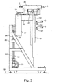
- Fig. 1 comprises the total designated 80 plant a frame 89, are mounted on the two squeezing rollers 1 for forming the incoming in their nip glass tube strand 81 and downstream of two pulleys 2 to the formed glass tube strand in the direction of the drawing machine 82 with the two Switzerlandrollenzipen 83, 84th redirect.
- a housing cover 45 in which the squeezing rollers 1 are arranged, shields the deformation area in the area of the squeezing rollers 1 from the outside environment.
- the outer diameter of the glass tube strand 81 is preferably optically measured with the aid of a measuring device 86 without contact and very particularly preferably.
- the inner diameter of the glass tube strand 81 is optically measured by means of a measuring device 87, in particular by means of a triangulation method.
- the measuring location of the measuring device 87 is preferably as close as possible to the measuring location of the measuring device 86.
- the two squeezing rollers 1 are automatically measured, for example by means of inductive displacement measurement, and the concentricity error and / or the outside diameter fluctuations of the squeezing rollers are determined.
- the conveyed length of the pipe string 81 is measured by means of a measuring device 91, preferably contactless.
- the relevant components of the system 80 are controlled or regulated by a control or regulating device 88, in particular by a CPU based on a software designed for this purpose.
- a control or regulating device 88 in particular by a CPU based on a software designed for this purpose.
- This can be controlled or regulated to a constant outer diameter of the glass tubes, or to a constant wall thickness of the glass tube or so that the concentricity error of the nip rolls 1 based on the width of the nip formed by these results in a minimum.
- the Fig. 2 shows a front view of a device for forming according to a first embodiment of the present invention.
- a base plate 30 is secured to the sliding table 35 is mounted vertically displaceable to allow adjustment of the height of the nip rollers 1. This height adjustment can be done manually using the handwheel 33, but also done by motor.
- two guide rods 31 are fixed, which guide the translation table vertically.
- the adjustment is accomplished by means of a threaded spindle 34, which engages on the one hand in the vertical adjusting device acting as a handwheel 33 and on the other hand in the displacement table 35 or with it.
- Fig. 2 is the support plate 20, on which the nip rollers (not shown) are mounted, connected via a horizontal adapter 38 and a vertical adapter 37 with the translation table 35.
- the handwheel 33 By adjusting the handwheel 33, the height of the nip rolls 1 can thus be adjusted.
- the height is adjusted so that a temperature range is provided along the glass tube strand which rapidly cools down in the withdrawal direction, in which the glass tube strand is suitably plastic in order to be able to be shaped precisely.
- This height can be set once, for example during commissioning of the system, or readjusted continuously or cyclically by means of the control or regulation 88.
- the height of the pulleys 2 and their position in a direction transverse to the drawing direction of the glass tube strand can be adjusted or readjusted independently of each other by means of the height adjustments 51 and 53 and by means of the transverse adjustments 52 and 54.
- the Fig. 3 shows the device after the Fig. 2 in a side view.
- the two nip rolls 1 forming a nip are mounted on a sliding table 12 which carries the two nip rolls 1.
- the displacement table 12 can be adjusted by means of the adjusting motor 25 in the axial direction of the nip rolls 1, so as to adjust the two squeezing rollers together axially.
- the two nip rolls 1 forming a nip can be mounted on a two-part displacement table 12, one half of which carries one of the nip rolls 1 and the other half carries the other of the two nip rolls 1. While one half of the sliding table 12 according to this embodiment is held stationary during the deformation, the other half of the sliding table 12 can be adjusted by means of the adjusting motor 25 in the axial direction of the nip rollers 1 relative to the first half of the sliding table 12.
- two mutually parallel guide rods 21 are mounted on respective bearing blocks 22 on the support plate 20.
- sliding elements (not shown), which engage in the guide rods 21, perform the axial adjustment of the sliding table.
- an adjusting threaded spindle 24 is further attached to the support plate, which is rotationally driven by the adjusting motor 25 and engages in a mating thread (not shown) on the underside of the sliding table 12.
- the adjusting motor 25 is designed as a synchronous motor, but may also be designed as a stepper motor to allow a stepwise axial adjustment, as explained in more detail below.
- the sliding table 12 is further provided a transverse guide rail 15, which is the adjustment of the sliding table (or according to the aforementioned alternative embodiment of one relative to the other half of the translation table 12) results in the adjustment of the nip width of the nip.
- an adjusting motor 13 is provided, which is fixed to the support plate 20.
- both squeezing rollers 1 can be adjusted axially.
- the two servomotors 9 are provided, which are coupled via a respective gear 10 and a respective clutch 8 with the associated nip roll 1.
- the clutch 8 is received in a clutch housing, the front flange-like end 11 is partially penetrated by the clutch 8.
- the coupling 8 couples with a spindle shaft 4, which is mounted by means of bearings 5 / spindle bearings 7 in a respective housing block designed as a bearing block 6.
- the nip rolls 1 may be attached to mounting flanges at the front end of the respective spindle shaft 4.
- a respective rotary feedthrough 3 which can be cooled by means of air or a fluid, such as water, to further cool the nip rolls. It should be noted, however, that due to the invention according to the invention permanently performed axial displacement of the nip rolls 1 during the deformation of the glass tube, such cooling is not essential.
- the position of preferably both nip rolls 1 is changed together by permanent axial adjustment of the position of the nip rolls so that a contact surface between the respective nip roll and the hot glass body is permanently varied or changes.
- This permanent axial adjustment of the position of the nip rolls preferably takes place in accordance with a predetermined movement function.
- This movement function is preferably a cyclical reciprocating movement of the respective squeegee roller 1 in its axial direction corresponding to a sawtooth or sine function or a comparable movement function, which is preferably performed in a temporally continuous manner. This is carried out in discrete steps of the same step size.
- the precise structure of the system allows the micrometer accurate delivery of the movable nip roll against the fixed nip roll. Disturbances in the area of the nip are reduced on the one hand by the covers 46 and 47 and on the other hand can be minimized by means of the control or regulation 88, as described above with reference to FIGS Fig. 1 described.
- the temperature influences in the region of the nip can be detected metrologically via a pyrometer and the rolling process can be corrected either manually or automatically.
- the structure of the system is the micrometer accurate manipulation of the inner diameter of a pinched tube in a hitherto unknown accuracy (measured, for example, ⁇ 20 microns) were possible.
- the nip rolls can be position-controlled in micro-grades so that the smallest gap width error of the two nip rolls can be determined.
- the synchronized rotation axes of the squeezing rollers can be driven by control technology with a differential speed in order to prevent curvature effects caused by the deflection of the glass strand.
- the drawing speed is set by the drawing machine, the rolling speed can be operated at a different speed, either to create a slack or to exert a pull on the glass strand, which has a significant effect on the geometry of the crimped pipe.
- the control and regulating circuit of the plant is made of a optical measuring system, that the inner diameter of the crimped tube micrometer-accurate measures and the recuperzisionsstellmotoren the respective axes (axes of rotation of the rollers, feed axes) formed. Furthermore, the pair of rollers is moved stepwise over a further actuator to minimize premature wear of the rollers, due to the high temperature influence of the still plastic glass.
- the plant and especially the squeeze rolls can be air- or water-cooled in order to minimize the temperature effects due to the conditions prevailing at the place of use.
- FIGS. 5a and 5b show two further perspective views of a device for forming according to the present invention.
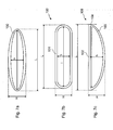
- FIGS. 7a to 7e show various examples of glass tubes with non-circular cross-section, which can be produced according to the present invention with high precision.
- an oval tube 100 is formed, the height H is smaller than the maximum transverse dimension L.
- the clear width in the direction of the semi-minor axis is designated by h.
- the wall thickness of such an oval tube can be constant over the entire circumference or, as in the Fig. 7a represented, vary continuously and mirror-symmetrically.
- Such an oval tube can be used for example as an intent filter for LEDs of flat screens. A 30% higher light output could be detected.
- such an oval tube can also be used as a medium tube for photobioreactors for irradiating microorganisms received in the medium tube or for solar thermal systems for heating a fluid which flows through the medium tube by means of sunlight, as follows executed.
- the formed tube 100 is substantially rectangular, with semicircular rounded side edges and two mutually parallel longitudinal sides 101 of constant wall thickness.
- the glass tube 100 has a flat longitudinal side 102 and a mirror-symmetrically and convexly curved surface 103, wherein the bending radii in the two corner regions 104 are very small.
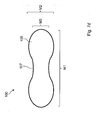
- the formed glass tube 100 is a total dumbbell-shaped, with two symmetrical oval side wings 105 of a height M2, which are connected to each other via a narrower connecting web 107 a height M3.
- the inventors have observed that such a glass tube with conventional process parameters for the formation of an oval tube, as described above with reference to Fig. 7a described forms, when the middle side wall portions on the broad side of the glass tube after forming slightly in the hot, plastically deformable state. These middle side wall sections can thereby come in stronger than in the Fig. 7d shown, wherein the side wall portions do not touch each other in the middle of the glass tube to give the dumbbell-shaped tube profile a comparatively high stability.
- the Fig. 7e shows the general structure of a glass tube, which is produced by a method according to the present invention.
- This has a central portion L3 with a profile deviating from the circular shape, for example formed as an oval tube, as described above with reference to FIG Fig. 7a described.
- the glass tube also has two open, ie not sealed or sealed, end portions L1 and L1 * which have a circular profile which preferably corresponds to the circular profile of the glass tube entering the nip between the nip rolls because the glass tube is in the end portions L1 and L1 * was not reshaped.
- the end sections L1 and L1 * go over transition sections L2 and L2 * continuously in the central portion L3 with the deviating from the circular profile over.
- the central portion L3 is formed by reshaping the glass tube entering the nip between the nip rolls.
- the width of the broad side of the glass tube corresponds to the distance of the nip rollers forming the nip.
- the end portions L1 and L1 * are preferably not reshaped.
- the end of the transitional sections L2, L2 * to the central portion L3 marks the gap width of the nip between the nip rolls, which corresponds to a maximum degree of deformation of the incoming into the nip Stahlsprofils or a minimum outer dimension of the formed glass tube, ie, for example, the height h of the broad side of the Oval tube 100 according to the Fig. 7a ,
- the tube according to the Fig. 7e are circumferential length of the central portion L3, that is, the non-circular profile, and the circumferential lengths of the end portions L1, L1 * of the tube with the circular profile equal.
- the profiles of the sections L2, L3 and L1 * can be specified by specifying the shape of the nip rolls and their operation suitable and varied in a simple manner.
- the central portion L3 may be formed drop-shaped as a whole, when the axes of the nip rolls, which form the nip, during the deformation of the central portion are adjusted so that they converge in a V-shape.
- the profile of the central portion L3 may vary axially when the squeeze rolls forming the nip have a non-circular profile, in particular an oval or polygonal profile.
- the central section L3 may have a profile such as that exemplified in FIG Fig.
- the nip rolls can be actively driven and / or additionally heated. Furthermore, the squeezing rollers can be adjusted axially and / or their angle of attack can be changed.
- the Fig. 8 shows a schematic flow diagram of a method according to the present invention for the preparation of in the Fig. 7e shown glass tube.
- a tube having a circular exit profile is provided.
- the material can be produced continuously by means of a suitable production process, for example by extruding a plastic, preferably a transparent plastic, or by continuously drawing a glass tube from a molten glass, for example by means of a down-draw method, Vello method or Danner method ,
- the tube is conveyed in a plastically deformable state through a nip, which is formed by at least two nip rolls. Depending on the material of the pipe, this may require some heating of the pipe.
- the pipe is conveyed further to the nip immediately after its manufacture, for example by drawing a glass tubing from a molten glass or extruding a plastic pipe.
- the nip has a first gap width, which is greater than or equal to an outer dimension of the output profile of the tube, ie the outer diameter of the incoming into the nip pipe string.
- preference is given to no deformation of the tube in the nip, since the nip rolls do not abut against the outer circumference of the tubing string.
- the tube length conveyed into the nip is measured, for example with the aid of the length measuring device 91 (cf. Fig. 1 ).
- the nip rolls remain in their quiescent state without the tube being formed in the nip.
- the width of the nip is started to be reduced by adjusting at least one nip roll in a direction perpendicular to the axial direction thereof. The instant of direct contact of the nip rolls on the outer circumference of the pipe string entering the nip marks the beginning of the transition region L2.
- the tube is increasingly reshaped until, finally, the width of the nip has reached a predetermined amount (second nip width) that corresponds, for example, to the minor axis of the oval tube to be produced.
- second nip width a predetermined amount that corresponds, for example, to the minor axis of the oval tube to be produced.
- the pipe After reaching the second gap width, which is smaller than the outer dimension of the initial profile of the incoming pipe into the nip, the pipe is deformed in the plastically deformable state to the non-circular profile L3.
- Conceivable here is the transformation to an oval tube, as exemplified in the Fig. 7a shown, but also to any other profiles that differ from the ideal circular shape and exemplified above with reference to FIGS. 7b to 7d have been described.
- the delivered pipe length continues to be measured. As long as the measured pipe length has not yet exceeded a predetermined value L3, the nip rolls remain in the state with the second nip width, in which the pipe is formed in the nip.
- the width of the nip is started to be increased again by adjusting at least one squeeze roller in a direction perpendicular to the axial direction thereof.
- the time of commencement of this enlargement of the nip marks the beginning of the rear transition region L2 *.
- tubes may be made in this manner whose end portions L1, L * are circular, that is, connectable by conventional tube connection technologies to connection means (e.g., inlet and outlet) or adjacent tubes, but at least one central one Section L3 have a suitable deviating from the circular shape profile.
- tubes with a section of the circular shape deviating profile nevertheless be connected by means of proven pipe connection technologies with connection means or adjacent pipes.
- arbitrary profile profiles can also be set in the axial direction of the tube. Basically symmetrical profile profiles are preferred, as in the Fig. 7e shown, since these can be produced with lower voltage usually. In principle, however, are also any other in the axial direction of the tube asymmetric profile profiles.
- Areas of application of such tubes, in particular glass tubes, are, for example: oval tubes with high geometrical accuracy for the use of hermetic packages for semiconductor nanoparticles in which a high geometrical accuracy (gap dimension) is important; Piston or sheath tubes for discharge lamps, in particular flash lamps in which the installation dimension, but not the light output should be minimized.
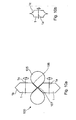
- FIG. 10a is shown in a schematic sectional view of the region of the nip formed by two nip rolls 1.
- the glass tube 100 passes through the nip perpendicular to the plane of the drawing.
- the squeezing rollers 1 rotate about the respective axis 1a.
- the squeezing rollers 1 on its outer circumference on a projection 1b, which in the illustrated embodiment, the shape of an isosceles triangle, although the present invention is basically not limited to this profile.
- the squeezing rollers 1 form a nip, widening symmetrically and wedge-shaped starting from the narrowest point, namely where the vertices of the projections 1 b are opposite each other.
- the glass tube 100 is deformed so much that it comes in the central region to a constriction 107, where the top and bottom of the glass tube touch and merge together to form a connecting web 107.
- Starting from the connecting web 107 extend oblique connecting legs 106 whose shape and inclination is determined by the profile of the projections 1 b of the nip rolls 1, which eventually pass into two spherical side wings 105.
- a thus formed glass tube 100 thus provides two flow channels, which are formed by the side wings 105. in the Region of the connecting web 107, these flow channels are separated from each other, so that, for example, in this area fluids can flow in opposite directions.
- Fig. 10b shows a further embodiment of a squeezer 1, which has a projection 1c with a concave curvature. This leads accordingly Fig. 10a in the region of the connecting leg to a correspondingly convex curvature of the glass tube (not shown).
- FIGS. 9a to 9c Two preferred applications of a glass tube made by a method according to the present invention will now be described.
- the Fig. 9a shows the use of such a transparent tube in a photobioreactor for growing microorganisms by irradiation with natural light.
- the transparent tube 100 which may be formed of glass or a suitable transparent plastic, there is a liquid 113, which receives the microorganisms 112 to be cultivated, for example algae, as a matrix.
- the tube 100 is connected via its end portions (not shown), which have the circular profile, with connecting means, ie an inlet and outlet (not shown), or with other tubes of the same type, possibly via intermediate or connecting pieces, so the liquid 113 with the microorganisms 112 can be pumped continuously or in cycles through the photobioreactor.
- the tube has at least one central portion with a profile deviating from the circular shape and is otherwise configured as described above with reference to FIG Fig. 7e described. This central portion is formed, for example, as the illustrated oval tube.
- the central portion (L3) of the tube 100 that is, for example, the illustrated oval tube, with its broader side facing the natural light source (sun) 110 faces. More specifically, the major axis which passes through the two foci of the oval tube 100 is oriented perpendicular to the direction of light incidence or to a direction of light incidence averaged over the usual course of irradiation.
- the natural light source by means of concave mirrors or similar optical imaging devices on the tube 100 suitably map, said in the Fig. 9a then the illustrated arrows should symbolize the direction of sunshine.
- the central portion (L3) of the tube so for example, the illustrated oval tube, arranged in a corresponding manner with its broader side facing the sunlight or the direction of the sun's rays.
- the tube 100 will generally not be facing exactly (in the mathematical sense) with its broadside towards the direction of sunshine, but only approximately because the tube 100 is generally facing is not tracked according to the changing position of the sun.
- the orientation of the tubes 100 of the photobioreactor could in principle also be provided in order to allow optimal irradiation of the sunlight into the tube 100 according to the invention.
- the image of the sunlight on the tube 100 is adjusted by suitably adjusting the concave mirror or similar optical imaging devices according to the position of the sun.
- the Fig. 9b shows the use of a transparent tube 100 made by a method according to the present invention in a photobioreactor for growing microorganisms by irradiation with artificial light.
- the artificial light source 115 is located at the focal point of a concave mirror 111 extending along and parallel to the respective central portion so that the light of the artificial light source 110 is imaged into an expanded light beam irradiating the tube 100.
- the central portion (L3) of the tube 100 that is, for example, the oval tube shown, arranged with its broader side facing the light source 115. More specifically, the major axis passing through the two foci of the oval tube 100 is oriented perpendicular to the light incident direction as dictated by the concave mirror 111 and the arrangement of the light source 115.
- an oval tube (with the same circumference) and a major axis ratio of, for example, 1.42: 1 has an area increased by a factor of 1.16. Due to the slightly smaller cross-section, the algae flow faster in the oval area than in the round area and are exposed shorter by a factor of 1.06. Taken together, however, a positive effect with a factor of 1.09 remains according to the invention.
- This factor corresponds to increased algae growth compared to a completely round tube.
- algae can be grown in tubes in which several tubes are connected to quasi-endless tubes (for example, up to 50m in length) and vertically stacked with stands and exposed to the sun or an artificial light source.
- the combination of oval tubes with round ends like As described above, it is advantageous to take advantage of the increased light output and conventional round tube joining techniques.
- the Fig. 9c shows another use of a tube 100 made by a method according to the present invention for solar thermal applications for heating a fluid by sunlight.
- the transparent tube 100 which may be formed of glass or a suitable plastic, there is a liquid 113 which is to be heated.
- the tube 100 is connected via its end portions (not shown), which have the circular profile, with connection means, ie an inlet and outlet (not shown), or with other tubes of the same type, so that the liquid 113 is continuously or clocked by the Solar thermal system can be pumped.
- the tube has at least one central portion with a profile deviating from the circular shape and is otherwise configured as described above with reference to FIG Fig. 7e described. This central portion is formed, for example, as the illustrated oval tube 100.
- the central portion (L3) of the tube so for example, the illustrated oval tube, arranged with its wider side facing a light source.
- the light of the sun 110 is imaged via a concave mirror 111 onto the tube 100, which extends along the respective central portion and parallel to it, so that the sunlight of the light source is imaged in an expanded light beam which irradiates the tube 100.
- the tube 100 is arranged with its wider side facing the concave mirror 111, which serves as a light source for heating the fluid 113 in the tube 100 here.
- the concave mirror 111 will be tracked according to the changing position of the sun.
- any deformable materials may be used, for example, glass, plastic or plastic composite materials.
- the material of the tube is suitably transparent in the wavelength range of the irradiating light.
- transparent types of glass for example, durane (Si0 2 -81%, B 2 0 3 - 13%, N 2 0 + K 2 0-4%, Al 2 0 3 - 2%), soda lime or Fiolax ® , or transparent Plastics selected from the group comprising: polymethyl methacrylate (PMMA), polycarbonate (PC), polyamide (PA), polyethylene (PE) polypropylene (PP), polystyrene (PS), poly-4-methylpentene-1 (PMP), polyvinyl chloride (PVC), cycloolefin copolymers (COC), styrene / butadiene / styrene block copolymer (SBS), methyl methacrylate / acrylonitrile / polybutadiene / styrene graft copolymers (MABS), aromatic polyesters (APE), polyestercarbonates (PEC), cellulose propionate (CP), polyetherfluoroethylene (PTFE ), PF
- the pipe length can be 0,20m - 10m
- the diameter in the round area can be larger than 8 mm and smaller than 200 mm
- the wall thicknesses can be in the range of 0,5 to 10mm.
- Oval tubes in the sense of the present application can be provided with principal axes a and b of the longest or shortest diameter) and size ratios 1 ⁇ a / b ⁇ 2 and in particular 1.2 ⁇ a / b ⁇ 1.6.
- the glass tube can be marked in accordance with the external dimension and / or internal dimension detected downstream of the nip by means of the measuring devices 86, 87, for example by labeling or by means of laser marking. Furthermore, the glass tube can also be sorted according to the outer dimension and / or inner dimension detected downstream of the nip by means of the measuring devices 86, 87.
- the requirements for the tolerances of the components are generally at a 10-fold accuracy of tolerance specification.
- the individual components of the device were set to max. +/- 3 ⁇ m tolerated. Note the temperature influence, as a temperature change of 1K leads to a gap dimension change of 1 ⁇ m. By means of a cooling system, therefore, optionally the temperature of the system can be kept as constant as possible.
- the roll surfaces usually heat up uncontrollably through the glass strand, which is formed by the above-described permanent axial adjustment of at least one of the nip rolls and preferably of both the nip Squeezing rolls can be avoided. This can be further supported by permanent monitoring and control of the gap width of the nip.
- FIG. 10 shows an exemplary connection assembly 190 of two tubes made by a method according to the present invention.
- the two end sections 203 with a circular profile are each surrounded by a sleeve-shaped pipe connector 204.
- the two pipe connectors 204 are preferably connected to each other, but may also be integrally formed.
- Fig. 11b Fig. 3 shows in a schematic representation a photobioreactor 200 for growing microorganisms by irradiation, for example algae, wherein the photobioreactor 200 comprises tubes made by a method according to the present invention.
- Growing algae use light and certain nutrients, especially carbon dioxide, soluble nitrogen compounds and phosphate.
- Daylight is usually used as light, but artificial light can be used as an alternative to daylight or in addition to it.
- a small amount of the microorganisms are admixed with a liquid, for example water, in particular fresh water or seawater, or a suitable nutrient fluid.
- the photobioreactor 200 comprises a plurality of tubes that are suitably transparent so that light can penetrate through them into the liquid that is in the tubes.
- the tubes each include non-circular profile sections 202 and circular profile sections 204 as described above.
- the tubes are connected to one another via connecting elements 204, which are designed, for example, as described above with reference to FIG Fig. 11a described.
- a plurality of tubes are connected in series in this manner to form a respective row.
- the individual rows are connected to each other via U-tubes 207, so that an overall meander-shaped arrangement of tubes is realized, in which the Liquid with the microorganisms is stored and flows properly.
- the respective first or last row of pipes can be connected via a connecting line 201 to storage containers, pumps, etc. (not shown).
- the tubes are held by means of holding elements 206 in a frame 205, which allows a suitable alignment of the tubes, as described above.
- the tubes have a section with a circular profile at both ends
- the tubes can be suitably cut to length at any other portions during or after their manufacture.
- tubes having a section with a circular profile for connection to adjacent tubes and at least one further section with a non-circular profile may be conceivable, the tubes being cut to length in this section with a non-circular profile.
- such tubes have an end with a circular profile and an opposite end with a non-circular profile.
- the tube can also be designed as a dumbbell-shaped double tube, ie without any end section with a circular profile, wherein the connection with the flow channels formed by the side wings 105 is then accomplished in another way, for example by means of hoses.
- the device is used for the transformation of glass tubes
- the device can be used in a similar manner also for forming tubes of other plastically permanently deformable materials.
- the starting glass tube preferably has a circular cross section and then the deformation takes place to a profile deviating therefrom in at least one central section.
- the pipe ends are formed in the region of the end sections with a constant profile and open, so not melted or otherwise closed.
Landscapes
- Chemical & Material Sciences (AREA)
- Engineering & Computer Science (AREA)
- Organic Chemistry (AREA)
- Health & Medical Sciences (AREA)
- Life Sciences & Earth Sciences (AREA)
- Materials Engineering (AREA)
- Bioinformatics & Cheminformatics (AREA)
- Wood Science & Technology (AREA)
- Zoology (AREA)
- Biotechnology (AREA)
- Genetics & Genomics (AREA)
- Microbiology (AREA)
- Sustainable Development (AREA)
- Biomedical Technology (AREA)
- Biochemistry (AREA)
- General Engineering & Computer Science (AREA)
- General Health & Medical Sciences (AREA)
- Physics & Mathematics (AREA)
- General Physics & Mathematics (AREA)
- Mechanical Engineering (AREA)
- Clinical Laboratory Science (AREA)
- Manufacturing & Machinery (AREA)
- Molecular Biology (AREA)
- Re-Forming, After-Treatment, Cutting And Transporting Of Glass Products (AREA)
- Shaping Of Tube Ends By Bending Or Straightening (AREA)
- Extrusion Moulding Of Plastics Or The Like (AREA)
- Casting Or Compression Moulding Of Plastics Or The Like (AREA)
Applications Claiming Priority (1)
| Application Number | Priority Date | Filing Date | Title |
|---|---|---|---|
| DE102013109454.6A DE102013109454B4 (de) | 2013-08-30 | 2013-08-30 | Verfahren zur Herstellung sowie Verwendung eines Rohrs mit einem abschnittsweise von einer Kreisform abweichenden Profil und kreisförmigen Endabschnitten und Verwendung einer Vorrichtung zur Herstellung eines Rohrs |
Publications (2)
| Publication Number | Publication Date |
|---|---|
| EP2842916A1 EP2842916A1 (de) | 2015-03-04 |
| EP2842916B1 true EP2842916B1 (de) | 2015-12-23 |
Family
ID=51399522
Family Applications (1)
| Application Number | Title | Priority Date | Filing Date |
|---|---|---|---|
| EP14181847.6A Not-in-force EP2842916B1 (de) | 2013-08-30 | 2014-08-21 | Verfahren und vorrichtung zur herstellung eines rohrs mit einem abschnittsweise von einer kreisform abweichenden profil und kreisförmigen endabschnitten. |
Country Status (7)
| Country | Link |
|---|---|
| US (1) | US10227252B2 (https=) |
| EP (1) | EP2842916B1 (https=) |
| JP (1) | JP6008915B2 (https=) |
| CN (1) | CN104418486B (https=) |
| BR (1) | BR102014021555A2 (https=) |
| DE (1) | DE102013109454B4 (https=) |
| ES (1) | ES2565988T3 (https=) |
Families Citing this family (15)
| Publication number | Priority date | Publication date | Assignee | Title |
|---|---|---|---|---|
| EP3333136B1 (de) * | 2016-12-08 | 2022-02-16 | Schott Ag | Verfahren zum weiterverarbeiten eines glasrohr-halbzeugs |
| US20180164226A1 (en) * | 2016-12-08 | 2018-06-14 | Schott Ag | Method for further processing a glass tube semi-finished product |
| DE102016123865A1 (de) * | 2016-12-08 | 2018-06-14 | Schott Ag | Verfahren zum Weiterverarbeiten eines Glasrohr-Halbzeugs einschließlich einer thermischen Umformung |
| DE102016124833A1 (de) | 2016-12-19 | 2018-06-21 | Schott Ag | Verfahren zum Herstellen eines Hohlglasprodukts aus einem Glasrohr-Halbzeug mit Markierungen, sowie Verwendungen hiervon |
| DE102016125129A1 (de) * | 2016-12-21 | 2018-06-21 | Schott Ag | Verfahren zum Herstellen eines Glasrohr-Halbzeugs oder eines daraus hergestellten Hohlglasprodukts mit Markierungen, sowie Verwendungen hiervon |
| CN110944951B (zh) * | 2017-03-24 | 2022-09-27 | 康宁股份有限公司 | 用于在管转换期间测量玻璃温度的系统及方法 |
| DE102017115397A1 (de) | 2017-07-10 | 2019-01-10 | Schott Schweiz Ag | Heißformgebungswerkzeug für die Herstellung von Glascontainern |
| CN111633968B (zh) * | 2020-06-03 | 2022-06-24 | 沈阳工业大学 | 一种大型航空玻璃保温拉伸装置 |
| DE102020114886A1 (de) | 2020-06-04 | 2021-12-09 | Gerresheimer Bünde Gmbh | Verfahren und eine Anlage zum Herstellen eines Glaszeuges |
| DE102020114880A1 (de) * | 2020-06-04 | 2021-12-09 | Gerresheimer Bünde Gmbh | Vorrichtung zum Umformen eines Glaszeuges |
| US12459852B2 (en) | 2021-05-24 | 2025-11-04 | Corning Incorporated | Feedback control systems and methods for glass tube converting processes |
| US11959054B2 (en) * | 2021-11-04 | 2024-04-16 | Upside Foods, Inc. | Substrate apparatus with multi-layer substrate for cell-based meat cultivators |
| CN114274430B (zh) * | 2021-12-22 | 2023-07-07 | 佛山市耐锢塑料机械有限公司 | 一种塑料薄膜生产设备的定型装置及其定型工艺 |
| CN116198104B (zh) * | 2023-02-10 | 2024-11-12 | 重庆交通大学 | 一种可折叠可微调的铝塑管矫直下管装置 |
| CN118459070B (zh) * | 2024-05-08 | 2024-11-01 | 枣庄市琢玉工艺品有限公司 | 一种玻璃器皿生产用的封底装置 |
Family Cites Families (18)
| Publication number | Priority date | Publication date | Assignee | Title |
|---|---|---|---|---|
| DE545449C (de) * | 1930-10-28 | 1932-02-29 | Patra Patent Treuhand | Vorrichtung zum Umformen von Glasroehren oder -staeben |
| DE1007962B (de) * | 1954-06-04 | 1957-05-09 | Siemens Ag | Verfahren zum Herstellen von Glasfolienbaendern |
| NL7510101A (nl) | 1975-08-27 | 1977-03-01 | Philips Nv | Werkwijze voor het omvormen van een glasbuis. |
| US4142514A (en) * | 1976-03-04 | 1979-03-06 | Solation Products, Inc. | Solar heat collector |
| JPS5947629U (ja) * | 1982-09-20 | 1984-03-29 | 東芝硝子株式会社 | 棒状ガラスの製造機 |
| JPS61224257A (ja) | 1985-03-27 | 1986-10-04 | Yamato Sangyo Kk | 放電管 |
| JP2920316B2 (ja) * | 1990-06-13 | 1999-07-19 | 光洋精工株式会社 | 平坦部付き円管の製造方法 |
| JPH06114910A (ja) | 1992-10-06 | 1994-04-26 | Sekisui Chem Co Ltd | 複合管の製造方法 |
| DE10014653A1 (de) | 2000-03-24 | 2001-10-11 | Simona Ag | Verfahren zum Herstellen eines nach dem Relining-Verfahren in eine schadhafte Rohrleitung oder einen schadhaften Kanal einstzbaren Rohrschusses |
| JP2006004660A (ja) * | 2004-06-15 | 2006-01-05 | Harison Toshiba Lighting Corp | 冷陰極蛍光ランプ及びその製造方法 |
| JP2006004880A (ja) * | 2004-06-21 | 2006-01-05 | Sanken Electric Co Ltd | 面光源装置 |
| JP2006315919A (ja) * | 2005-05-13 | 2006-11-24 | Harison Toshiba Lighting Corp | ガラス管成形装置およびその成形方法 |
| DE102006015223B3 (de) * | 2006-03-30 | 2007-08-30 | Schott Ag | Verfahren und Vorrichtung zur Herstellung eines Glasrohrs |
| WO2009051479A2 (en) * | 2007-10-15 | 2009-04-23 | Algaelink N.V. | Photobioreactor and method for the production of phototropic organisms |
| WO2009104297A1 (ja) * | 2008-02-22 | 2009-08-27 | シャープ株式会社 | 照明装置、表示装置、及びテレビ受信装置 |
| CN201326984Y (zh) * | 2008-11-28 | 2009-10-14 | 霍尼韦尔朗能电器系统技术(广东)有限公司 | 一种可拆卸的led灯灯头 |
| DE102009000154B4 (de) | 2009-01-12 | 2014-01-23 | Battenfeld-Cincinnati Germany Gmbh | Vorrichtung und Verfahren zum Führen und/oder Formen eines Kunststoffstranges |
| DE102010043587B4 (de) | 2010-11-08 | 2012-06-14 | Christoph Peppmeier | Zuchtvorrichtung für phototrophe Kulturen, sowie Verfahren zu deren Steuerung |
-
2013
- 2013-08-30 DE DE102013109454.6A patent/DE102013109454B4/de not_active Expired - Fee Related
-
2014
- 2014-08-21 EP EP14181847.6A patent/EP2842916B1/de not_active Not-in-force
- 2014-08-21 ES ES14181847.6T patent/ES2565988T3/es active Active
- 2014-08-28 JP JP2014174572A patent/JP6008915B2/ja not_active Expired - Fee Related
- 2014-08-28 US US14/470,970 patent/US10227252B2/en not_active Expired - Fee Related
- 2014-08-29 BR BR102014021555A patent/BR102014021555A2/pt not_active Application Discontinuation
- 2014-09-01 CN CN201410441690.4A patent/CN104418486B/zh not_active Expired - Fee Related
Also Published As
| Publication number | Publication date |
|---|---|
| US20150064779A1 (en) | 2015-03-05 |
| US10227252B2 (en) | 2019-03-12 |
| ES2565988T3 (es) | 2016-04-08 |
| JP2015107636A (ja) | 2015-06-11 |
| DE102013109454B4 (de) | 2018-03-22 |
| BR102014021555A2 (pt) | 2016-08-16 |
| JP6008915B2 (ja) | 2016-10-19 |
| EP2842916A1 (de) | 2015-03-04 |
| DE102013109454A1 (de) | 2015-03-05 |
| CN104418486B (zh) | 2018-10-30 |
| CN104418486A (zh) | 2015-03-18 |
Similar Documents
| Publication | Publication Date | Title |
|---|---|---|
| EP2842916B1 (de) | Verfahren und vorrichtung zur herstellung eines rohrs mit einem abschnittsweise von einer kreisform abweichenden profil und kreisförmigen endabschnitten. | |
| EP2695862B1 (de) | Verfahren und vorrichtung zum umformen eines länglichen glaskörpers sowie verwendung hiervon | |
| EP3266590B1 (de) | Blasfolienanlage, verfahren zum herstellen einer blasfolienbahn und damit hergestellte folie | |
| EP2818454B1 (de) | Glasbearbeitungsvorrichtung und Bodenmaschine hierfür zum Herstellen von Glasbehältern | |
| DE60116471T2 (de) | Verfahren und fertigungsstrasse zur kontinuierlichen herstellung von biaxial-gereckten kunststoffrohren | |
| DE102011014474B4 (de) | Schnecke | |
| DE60003163T2 (de) | Rohr aus thermoplastischem kunststoff | |
| DE69412906T2 (de) | Glaspolyedern und Verfahren zu ihrer Herstellung | |
| DE112013006145B4 (de) | Verfahren zur Herstellung eines Glasformkörpers und Formwerkzeug | |
| DE3121524A1 (de) | Verfahren zur herstellung eines rohrfoermigen koerpers und vorrichtung hierfuer | |
| EP2548850B1 (de) | Verfahren und Vorrichtung zur bevorzugt kontinuierlichen Herstellung von Glasrohren mit einem vorbestimmten Innenprofil | |
| DE102012025610B4 (de) | Vorrichtung zum Umformen eines länglichen Glaskörpers sowie Vorrichtung zum Herstellen eines länglichen Glaskörpers | |
| EP3275846B1 (de) | Verfahren zur lasergestützten umformung von glaskörpern | |
| EP2900447A2 (de) | Heissstempelverfahren | |
| DE102004007560B4 (de) | Vorrichtung und Ziehtank zur Herstellung von dünnen Glasscheiben | |
| EP3511301A1 (de) | Verfahren und vorrichtung zur herstellung von glasvorprodukten und von glasprodukten | |
| DE10348098A1 (de) | Vorrichtung und Verfahren zum Herstellen von Rohren oder Stäben | |
| EP3288694B1 (de) | Verfahren zum induktionsbiegeumformen eines druckfesten rohrs mit grosser wandstärke und grossem durchmesser und induktions-rohrbiegevorrichtung | |
| DE102005063041B4 (de) | Stufenlose einstellbare Kalibrierhülse für extrudierte Kunststoffrohre | |
| EP3392215A1 (de) | Vorrichtung und verfahren zur kühlung eines mittels rohrziehen gefertigten glasstrangs | |
| DE102018209353B4 (de) | Verfahren zum Biegen eines Kunststoffrohrs | |
| DE102015001841A1 (de) | Verfahren zum Betreiben einer Blasfolienanlage, Kalibriereinheit und Blasfolienanlage | |
| EP2626188B1 (de) | Verstellbares Kalibrierverfahren | |
| DE102006024566A1 (de) | Verfahren und Vorrichtung zur Herstellung eines Glasrohrs, Glasrohr und dessen Verwendung | |
| DE69612014T2 (de) | Vorrichtung zum formen und kühlen von wellrohren aus kunststoff |
Legal Events
| Date | Code | Title | Description |
|---|---|---|---|
| 17P | Request for examination filed |
Effective date: 20140821 |
|
| AK | Designated contracting states |
Kind code of ref document: A1 Designated state(s): AL AT BE BG CH CY CZ DE DK EE ES FI FR GB GR HR HU IE IS IT LI LT LU LV MC MK MT NL NO PL PT RO RS SE SI SK SM TR |
|
| AX | Request for extension of the european patent |
Extension state: BA ME |
|
| PUAI | Public reference made under article 153(3) epc to a published international application that has entered the european phase |
Free format text: ORIGINAL CODE: 0009012 |
|
| R17P | Request for examination filed (corrected) |
Effective date: 20150209 |
|
| RBV | Designated contracting states (corrected) |
Designated state(s): AL AT BE BG CH CY CZ DE DK EE ES FI FR GB GR HR HU IE IS IT LI LT LU LV MC MK MT NL NO PL PT RO RS SE SI SK SM TR |
|
| GRAP | Despatch of communication of intention to grant a patent |
Free format text: ORIGINAL CODE: EPIDOSNIGR1 |
|
| RIC1 | Information provided on ipc code assigned before grant |
Ipc: C03B 23/09 20060101ALN20150610BHEP Ipc: C03B 23/045 20060101ALI20150610BHEP Ipc: G01B 11/04 20060101ALI20150610BHEP Ipc: C03B 23/055 20060101AFI20150610BHEP Ipc: G01B 11/08 20060101ALI20150610BHEP Ipc: C03B 23/049 20060101ALI20150610BHEP Ipc: G01B 11/12 20060101ALI20150610BHEP Ipc: B29K 105/00 20060101ALI20150610BHEP Ipc: B29C 53/20 20060101ALI20150610BHEP Ipc: C12M 1/12 20060101ALI20150610BHEP Ipc: B29K 101/12 20060101ALI20150610BHEP Ipc: C12M 1/00 20060101ALI20150610BHEP Ipc: B29C 53/08 20060101ALI20150610BHEP |
|
| INTG | Intention to grant announced |
Effective date: 20150703 |
|
| RIC1 | Information provided on ipc code assigned before grant |
Ipc: C03B 23/049 20060101ALI20150623BHEP Ipc: B29C 53/20 20060101ALI20150623BHEP Ipc: C12M 1/12 20060101ALI20150623BHEP Ipc: G01B 11/08 20060101ALI20150623BHEP Ipc: C03B 23/055 20060101AFI20150623BHEP Ipc: C03B 23/09 20060101ALN20150623BHEP Ipc: G01B 11/04 20060101ALI20150623BHEP Ipc: C03B 23/045 20060101ALI20150623BHEP Ipc: G01B 11/12 20060101ALI20150623BHEP Ipc: B29K 101/12 20060101ALI20150623BHEP Ipc: C12M 1/00 20060101ALI20150623BHEP Ipc: B29C 53/08 20060101ALI20150623BHEP Ipc: B29K 105/00 20060101ALI20150623BHEP |
|
| GRAS | Grant fee paid |
Free format text: ORIGINAL CODE: EPIDOSNIGR3 |
|
| GRAA | (expected) grant |
Free format text: ORIGINAL CODE: 0009210 |
|
| AK | Designated contracting states |
Kind code of ref document: B1 Designated state(s): AL AT BE BG CH CY CZ DE DK EE ES FI FR GB GR HR HU IE IS IT LI LT LU LV MC MK MT NL NO PL PT RO RS SE SI SK SM TR |
|
| REG | Reference to a national code |
Ref country code: GB Ref legal event code: FG4D Free format text: NOT ENGLISH |
|
| REG | Reference to a national code |
Ref country code: CH Ref legal event code: EP |
|
| REG | Reference to a national code |
Ref country code: IE Ref legal event code: FG4D Free format text: LANGUAGE OF EP DOCUMENT: GERMAN |
|
| REG | Reference to a national code |
Ref country code: AT Ref legal event code: REF Ref document number: 766476 Country of ref document: AT Kind code of ref document: T Effective date: 20160115 |
|
| REG | Reference to a national code |
Ref country code: DE Ref legal event code: R096 Ref document number: 502014000238 Country of ref document: DE |
|
| REG | Reference to a national code |
Ref country code: ES Ref legal event code: FG2A Ref document number: 2565988 Country of ref document: ES Kind code of ref document: T3 Effective date: 20160408 |
|
| REG | Reference to a national code |
Ref country code: LT Ref legal event code: MG4D |
|
| REG | Reference to a national code |
Ref country code: NL Ref legal event code: MP Effective date: 20151223 |
|
| PG25 | Lapsed in a contracting state [announced via postgrant information from national office to epo] |
Ref country code: LT Free format text: LAPSE BECAUSE OF FAILURE TO SUBMIT A TRANSLATION OF THE DESCRIPTION OR TO PAY THE FEE WITHIN THE PRESCRIBED TIME-LIMIT Effective date: 20151223 Ref country code: NO Free format text: LAPSE BECAUSE OF FAILURE TO SUBMIT A TRANSLATION OF THE DESCRIPTION OR TO PAY THE FEE WITHIN THE PRESCRIBED TIME-LIMIT Effective date: 20160323 Ref country code: HR Free format text: LAPSE BECAUSE OF FAILURE TO SUBMIT A TRANSLATION OF THE DESCRIPTION OR TO PAY THE FEE WITHIN THE PRESCRIBED TIME-LIMIT Effective date: 20151223 |
|
| PG25 | Lapsed in a contracting state [announced via postgrant information from national office to epo] |
Ref country code: LV Free format text: LAPSE BECAUSE OF FAILURE TO SUBMIT A TRANSLATION OF THE DESCRIPTION OR TO PAY THE FEE WITHIN THE PRESCRIBED TIME-LIMIT Effective date: 20151223 Ref country code: FI Free format text: LAPSE BECAUSE OF FAILURE TO SUBMIT A TRANSLATION OF THE DESCRIPTION OR TO PAY THE FEE WITHIN THE PRESCRIBED TIME-LIMIT Effective date: 20151223 Ref country code: RS Free format text: LAPSE BECAUSE OF FAILURE TO SUBMIT A TRANSLATION OF THE DESCRIPTION OR TO PAY THE FEE WITHIN THE PRESCRIBED TIME-LIMIT Effective date: 20151223 Ref country code: NL Free format text: LAPSE BECAUSE OF FAILURE TO SUBMIT A TRANSLATION OF THE DESCRIPTION OR TO PAY THE FEE WITHIN THE PRESCRIBED TIME-LIMIT Effective date: 20151223 Ref country code: GR Free format text: LAPSE BECAUSE OF FAILURE TO SUBMIT A TRANSLATION OF THE DESCRIPTION OR TO PAY THE FEE WITHIN THE PRESCRIBED TIME-LIMIT Effective date: 20160324 Ref country code: SE Free format text: LAPSE BECAUSE OF FAILURE TO SUBMIT A TRANSLATION OF THE DESCRIPTION OR TO PAY THE FEE WITHIN THE PRESCRIBED TIME-LIMIT Effective date: 20151223 |
|
| PG25 | Lapsed in a contracting state [announced via postgrant information from national office to epo] |
Ref country code: SM Free format text: LAPSE BECAUSE OF FAILURE TO SUBMIT A TRANSLATION OF THE DESCRIPTION OR TO PAY THE FEE WITHIN THE PRESCRIBED TIME-LIMIT Effective date: 20151223 Ref country code: IS Free format text: LAPSE BECAUSE OF FAILURE TO SUBMIT A TRANSLATION OF THE DESCRIPTION OR TO PAY THE FEE WITHIN THE PRESCRIBED TIME-LIMIT Effective date: 20160423 Ref country code: PL Free format text: LAPSE BECAUSE OF FAILURE TO SUBMIT A TRANSLATION OF THE DESCRIPTION OR TO PAY THE FEE WITHIN THE PRESCRIBED TIME-LIMIT Effective date: 20151223 Ref country code: EE Free format text: LAPSE BECAUSE OF FAILURE TO SUBMIT A TRANSLATION OF THE DESCRIPTION OR TO PAY THE FEE WITHIN THE PRESCRIBED TIME-LIMIT Effective date: 20151223 Ref country code: SK Free format text: LAPSE BECAUSE OF FAILURE TO SUBMIT A TRANSLATION OF THE DESCRIPTION OR TO PAY THE FEE WITHIN THE PRESCRIBED TIME-LIMIT Effective date: 20151223 Ref country code: PT Free format text: LAPSE BECAUSE OF FAILURE TO SUBMIT A TRANSLATION OF THE DESCRIPTION OR TO PAY THE FEE WITHIN THE PRESCRIBED TIME-LIMIT Effective date: 20160426 Ref country code: RO Free format text: LAPSE BECAUSE OF FAILURE TO SUBMIT A TRANSLATION OF THE DESCRIPTION OR TO PAY THE FEE WITHIN THE PRESCRIBED TIME-LIMIT Effective date: 20151223 |
|
| REG | Reference to a national code |
Ref country code: DE Ref legal event code: R097 Ref document number: 502014000238 Country of ref document: DE |
|
| PLBE | No opposition filed within time limit |
Free format text: ORIGINAL CODE: 0009261 |
|
| STAA | Information on the status of an ep patent application or granted ep patent |
Free format text: STATUS: NO OPPOSITION FILED WITHIN TIME LIMIT |
|
| PG25 | Lapsed in a contracting state [announced via postgrant information from national office to epo] |
Ref country code: DK Free format text: LAPSE BECAUSE OF FAILURE TO SUBMIT A TRANSLATION OF THE DESCRIPTION OR TO PAY THE FEE WITHIN THE PRESCRIBED TIME-LIMIT Effective date: 20151223 |
|
| 26N | No opposition filed |
Effective date: 20160926 |
|
| PG25 | Lapsed in a contracting state [announced via postgrant information from national office to epo] |
Ref country code: BE Free format text: LAPSE BECAUSE OF NON-PAYMENT OF DUE FEES Effective date: 20160831 |
|
| PG25 | Lapsed in a contracting state [announced via postgrant information from national office to epo] |
Ref country code: SI Free format text: LAPSE BECAUSE OF FAILURE TO SUBMIT A TRANSLATION OF THE DESCRIPTION OR TO PAY THE FEE WITHIN THE PRESCRIBED TIME-LIMIT Effective date: 20151223 |
|
| PG25 | Lapsed in a contracting state [announced via postgrant information from national office to epo] |
Ref country code: MC Free format text: LAPSE BECAUSE OF FAILURE TO SUBMIT A TRANSLATION OF THE DESCRIPTION OR TO PAY THE FEE WITHIN THE PRESCRIBED TIME-LIMIT Effective date: 20151223 |
|
| REG | Reference to a national code |
Ref country code: FR Ref legal event code: ST Effective date: 20170428 |
|
| REG | Reference to a national code |
Ref country code: IE Ref legal event code: MM4A |
|
| PG25 | Lapsed in a contracting state [announced via postgrant information from national office to epo] |
Ref country code: IE Free format text: LAPSE BECAUSE OF NON-PAYMENT OF DUE FEES Effective date: 20160821 Ref country code: FR Free format text: LAPSE BECAUSE OF NON-PAYMENT OF DUE FEES Effective date: 20160831 |
|
| PG25 | Lapsed in a contracting state [announced via postgrant information from national office to epo] |
Ref country code: LU Free format text: LAPSE BECAUSE OF NON-PAYMENT OF DUE FEES Effective date: 20160821 |
|
| REG | Reference to a national code |
Ref country code: CH Ref legal event code: PL |
|
| PG25 | Lapsed in a contracting state [announced via postgrant information from national office to epo] |
Ref country code: CH Free format text: LAPSE BECAUSE OF NON-PAYMENT OF DUE FEES Effective date: 20170831 Ref country code: LI Free format text: LAPSE BECAUSE OF NON-PAYMENT OF DUE FEES Effective date: 20170831 |
|
| PG25 | Lapsed in a contracting state [announced via postgrant information from national office to epo] |
Ref country code: HU Free format text: LAPSE BECAUSE OF FAILURE TO SUBMIT A TRANSLATION OF THE DESCRIPTION OR TO PAY THE FEE WITHIN THE PRESCRIBED TIME-LIMIT; INVALID AB INITIO Effective date: 20140821 |
|
| PG25 | Lapsed in a contracting state [announced via postgrant information from national office to epo] |
Ref country code: MT Free format text: LAPSE BECAUSE OF FAILURE TO SUBMIT A TRANSLATION OF THE DESCRIPTION OR TO PAY THE FEE WITHIN THE PRESCRIBED TIME-LIMIT Effective date: 20151223 Ref country code: MK Free format text: LAPSE BECAUSE OF FAILURE TO SUBMIT A TRANSLATION OF THE DESCRIPTION OR TO PAY THE FEE WITHIN THE PRESCRIBED TIME-LIMIT Effective date: 20151223 Ref country code: CY Free format text: LAPSE BECAUSE OF FAILURE TO SUBMIT A TRANSLATION OF THE DESCRIPTION OR TO PAY THE FEE WITHIN THE PRESCRIBED TIME-LIMIT Effective date: 20151223 |
|
| PG25 | Lapsed in a contracting state [announced via postgrant information from national office to epo] |
Ref country code: BG Free format text: LAPSE BECAUSE OF FAILURE TO SUBMIT A TRANSLATION OF THE DESCRIPTION OR TO PAY THE FEE WITHIN THE PRESCRIBED TIME-LIMIT Effective date: 20151223 |
|
| PG25 | Lapsed in a contracting state [announced via postgrant information from national office to epo] |
Ref country code: AL Free format text: LAPSE BECAUSE OF FAILURE TO SUBMIT A TRANSLATION OF THE DESCRIPTION OR TO PAY THE FEE WITHIN THE PRESCRIBED TIME-LIMIT Effective date: 20151223 Ref country code: TR Free format text: LAPSE BECAUSE OF FAILURE TO SUBMIT A TRANSLATION OF THE DESCRIPTION OR TO PAY THE FEE WITHIN THE PRESCRIBED TIME-LIMIT Effective date: 20151223 |
|
| PGFP | Annual fee paid to national office [announced via postgrant information from national office to epo] |
Ref country code: DE Payment date: 20180823 Year of fee payment: 5 Ref country code: IT Payment date: 20180830 Year of fee payment: 5 Ref country code: ES Payment date: 20180921 Year of fee payment: 5 |
|
| PGFP | Annual fee paid to national office [announced via postgrant information from national office to epo] |
Ref country code: CZ Payment date: 20180820 Year of fee payment: 5 |
|
| GBPC | Gb: european patent ceased through non-payment of renewal fee |
Effective date: 20180821 |
|
| PG25 | Lapsed in a contracting state [announced via postgrant information from national office to epo] |
Ref country code: GB Free format text: LAPSE BECAUSE OF NON-PAYMENT OF DUE FEES Effective date: 20180821 |
|
| REG | Reference to a national code |
Ref country code: DE Ref legal event code: R119 Ref document number: 502014000238 Country of ref document: DE |
|
| PG25 | Lapsed in a contracting state [announced via postgrant information from national office to epo] |
Ref country code: CZ Free format text: LAPSE BECAUSE OF NON-PAYMENT OF DUE FEES Effective date: 20190821 |
|
| PG25 | Lapsed in a contracting state [announced via postgrant information from national office to epo] |
Ref country code: DE Free format text: LAPSE BECAUSE OF NON-PAYMENT OF DUE FEES Effective date: 20200303 |
|
| PG25 | Lapsed in a contracting state [announced via postgrant information from national office to epo] |
Ref country code: IT Free format text: LAPSE BECAUSE OF NON-PAYMENT OF DUE FEES Effective date: 20190821 |
|
| REG | Reference to a national code |
Ref country code: AT Ref legal event code: MM01 Ref document number: 766476 Country of ref document: AT Kind code of ref document: T Effective date: 20190821 |
|
| PG25 | Lapsed in a contracting state [announced via postgrant information from national office to epo] |
Ref country code: AT Free format text: LAPSE BECAUSE OF NON-PAYMENT OF DUE FEES Effective date: 20190821 |
|
| REG | Reference to a national code |
Ref country code: ES Ref legal event code: FD2A Effective date: 20210105 |
|
| PG25 | Lapsed in a contracting state [announced via postgrant information from national office to epo] |
Ref country code: ES Free format text: LAPSE BECAUSE OF NON-PAYMENT OF DUE FEES Effective date: 20190822 |