EP2842504A1 - Knochenschraube, Implantatplatte und System daraus - Google Patents
Knochenschraube, Implantatplatte und System daraus Download PDFInfo
- Publication number
- EP2842504A1 EP2842504A1 EP14182914.3A EP14182914A EP2842504A1 EP 2842504 A1 EP2842504 A1 EP 2842504A1 EP 14182914 A EP14182914 A EP 14182914A EP 2842504 A1 EP2842504 A1 EP 2842504A1
- Authority
- EP
- European Patent Office
- Prior art keywords
- bone
- implant plate
- bone screw
- screw
- flank
- Prior art date
- Legal status (The legal status is an assumption and is not a legal conclusion. Google has not performed a legal analysis and makes no representation as to the accuracy of the status listed.)
- Granted
Links
Images

Classifications
-
- A—HUMAN NECESSITIES
- A61—MEDICAL OR VETERINARY SCIENCE; HYGIENE
- A61B—DIAGNOSIS; SURGERY; IDENTIFICATION
- A61B17/00—Surgical instruments, devices or methods
- A61B17/56—Surgical instruments or methods for treatment of bones or joints; Devices specially adapted therefor
- A61B17/58—Surgical instruments or methods for treatment of bones or joints; Devices specially adapted therefor for osteosynthesis, e.g. bone plates, screws or setting implements
- A61B17/68—Internal fixation devices, including fasteners and spinal fixators, even if a part thereof projects from the skin
- A61B17/84—Fasteners therefor or fasteners being internal fixation devices
- A61B17/86—Pins or screws or threaded wires; nuts therefor
- A61B17/8605—Heads, i.e. proximal ends projecting from bone
-
- A—HUMAN NECESSITIES
- A61—MEDICAL OR VETERINARY SCIENCE; HYGIENE
- A61B—DIAGNOSIS; SURGERY; IDENTIFICATION
- A61B17/00—Surgical instruments, devices or methods
- A61B17/56—Surgical instruments or methods for treatment of bones or joints; Devices specially adapted therefor
- A61B17/58—Surgical instruments or methods for treatment of bones or joints; Devices specially adapted therefor for osteosynthesis, e.g. bone plates, screws or setting implements
- A61B17/68—Internal fixation devices, including fasteners and spinal fixators, even if a part thereof projects from the skin
- A61B17/80—Cortical plates, i.e. bone plates; Instruments for holding or positioning cortical plates, or for compressing bones attached to cortical plates
- A61B17/8052—Cortical plates, i.e. bone plates; Instruments for holding or positioning cortical plates, or for compressing bones attached to cortical plates immobilised relative to screws by interlocking form of the heads and plate holes, e.g. conical or threaded
-
- A—HUMAN NECESSITIES
- A61—MEDICAL OR VETERINARY SCIENCE; HYGIENE
- A61B—DIAGNOSIS; SURGERY; IDENTIFICATION
- A61B17/00—Surgical instruments, devices or methods
- A61B17/56—Surgical instruments or methods for treatment of bones or joints; Devices specially adapted therefor
- A61B17/58—Surgical instruments or methods for treatment of bones or joints; Devices specially adapted therefor for osteosynthesis, e.g. bone plates, screws or setting implements
- A61B17/68—Internal fixation devices, including fasteners and spinal fixators, even if a part thereof projects from the skin
- A61B17/80—Cortical plates, i.e. bone plates; Instruments for holding or positioning cortical plates, or for compressing bones attached to cortical plates
- A61B17/8052—Cortical plates, i.e. bone plates; Instruments for holding or positioning cortical plates, or for compressing bones attached to cortical plates immobilised relative to screws by interlocking form of the heads and plate holes, e.g. conical or threaded
- A61B17/8057—Cortical plates, i.e. bone plates; Instruments for holding or positioning cortical plates, or for compressing bones attached to cortical plates immobilised relative to screws by interlocking form of the heads and plate holes, e.g. conical or threaded the interlocking form comprising a thread
-
- A—HUMAN NECESSITIES
- A61—MEDICAL OR VETERINARY SCIENCE; HYGIENE
- A61B—DIAGNOSIS; SURGERY; IDENTIFICATION
- A61B17/00—Surgical instruments, devices or methods
- A61B17/56—Surgical instruments or methods for treatment of bones or joints; Devices specially adapted therefor
- A61B17/58—Surgical instruments or methods for treatment of bones or joints; Devices specially adapted therefor for osteosynthesis, e.g. bone plates, screws or setting implements
- A61B17/68—Internal fixation devices, including fasteners and spinal fixators, even if a part thereof projects from the skin
- A61B17/84—Fasteners therefor or fasteners being internal fixation devices
- A61B17/86—Pins or screws or threaded wires; nuts therefor
- A61B17/866—Material or manufacture
-
- A—HUMAN NECESSITIES
- A61—MEDICAL OR VETERINARY SCIENCE; HYGIENE
- A61B—DIAGNOSIS; SURGERY; IDENTIFICATION
- A61B17/00—Surgical instruments, devices or methods
- A61B17/56—Surgical instruments or methods for treatment of bones or joints; Devices specially adapted therefor
- A61B17/58—Surgical instruments or methods for treatment of bones or joints; Devices specially adapted therefor for osteosynthesis, e.g. bone plates, screws or setting implements
- A61B17/68—Internal fixation devices, including fasteners and spinal fixators, even if a part thereof projects from the skin
- A61B17/84—Fasteners therefor or fasteners being internal fixation devices
- A61B17/86—Pins or screws or threaded wires; nuts therefor
- A61B17/8685—Pins or screws or threaded wires; nuts therefor comprising multiple separate parts
Definitions
- the present invention relates to a bone screw for variable angle or polyaxial screwing an implant plate with a bone. It further relates to an implant plate for such a screw connection and finally to a system comprising such a bone screw and such an implant plate.
- the EP2 308 403 B1 discloses a bone screw having a bone threaded stem and having a conically sheathed head thread axially adjacent the bone thread.
- the head thread runs at an end remote from the bone thread in a circumferential recess.
- the undercut has an undercut flank intended for blocking with the bone plate. In this case, cold welding can be prevented because the blocking takes place immediately after hitting the undercut on the bone plate.
- this screw there is the disadvantage that the screw head is engaged only over a small area with the bone plate. With a diagonal screwing the bone screw into the bone plate it can despite the undercut to chip formation come because the head thread of the bone screw cuts when screwing into the material of the bone plate and it comes to material removal.
- a angle stable variable screw for a bone plate for osteosynthesis known.
- a star-shaped opening is formed with an internal thread. This is due to the star shape of threaded portions and formed between two adjacent threaded portions bulges.
- the thread core diameter tapers in the screwing direction.
- a thread-free pan for receiving a screw head.
- the bone plate can be used with a round or with a threaded head screw, the latter can be locked angularly stable in the plate opening, the round head screw but not. If a threaded head screw is screwed obliquely into the plate opening, the head thread of the screw cuts partially into the threaded sections of the star-shaped opening, which leads to disadvantageous material removal and chip formation.
- a stabilization system for bones is known.
- This has a substantially T-shaped bone plate with through-holes provided with an internal thread and a set of predetermined unidirectionally screw-in screws and a set by a surgeon selectable multidirectionally screwed screws.
- the screws have screw heads provided with a head thread in various embodiments. In an oblique screwing into the through holes of the plate, the head thread cuts into the material of the plate, in particular into the internal thread in the respective through hole, whereby it comes at a disadvantage to chip formation.
- the system consists of a bone plate with a through hole inserted therein, a bone screw with a bone and a head thread and a cup-shaped spacer with internal thread.
- the passage opening is provided with a part-spherical flange whose contour fits the spacer. This must be introduced by the surgeon from the bottom of the bone plate in the through hole, whereupon its cup-shaped contour rests against the part-spherical flange.
- the bone screw is inserted from the opposite side into the passage opening. Their bone thread is smaller than the internal thread of the spacer, so that there is no intervention between them.
- the head thread of the bone screw engages in the internal thread of the spacer.
- the spacer With a deep screwing the bone screw, when the head of the bone screw abuts against the top of the bone plate, by this engagement, the spacer is pressed against the part-spherical flange of the bone plate. The spacer and thus also screwed therein bone screw are then fixed in position relative to the bone plate. Due to the partial spherical surfaces of spacer and flange, the system is variable in angle and can be fixed independently of the screw-in angle. Since the internal thread of the spacer and the head thread of the bone screw are always aligned with each other, there is no chip formation. However, the system has many components, is complex to produce and complex in its handling.
- the object of the invention is to enable a surgeon to remove bone screws in the desired direction, depending on the course of the fracture. variably multidirectional, to screw into an implant plate and a bone.
- This chip formation should not occur and the bone screw safely and permanently secured against the implant plate or be blocked, so that a postoperative loosening of the screw and thus their lateral emigration to adjacent soft parts are prevented or at least slowed down.
- the connection should also after a certain time, e.g. as part of an implant removal, easy to be solved again.
- the system and its components are said to be simple and inexpensive to manufacture and, in particular, easy to use for the surgeon using them.
- a bone screw for angularly variable screwing of an implant plate with a bone wherein the bone screw has a shaft with a bone thread and at one end of the shaft Has screw head, wherein in the screw head at its side facing the shaft, a circumferentially circumferential groove-shaped recess is formed, which groove-shaped recess has a groove flank, which is intended for clamping, bracing or blocking with an implant plate.
- the bone screw is particularly suitable and intended for variable-angle screwing with an implant plate according to one of claims 7 to 13.
- an implant plate for angularly variable screwing of a bone screw with a bone
- the implant plate has at least one passage opening for receiving the bone screw, wherein the passage opening on the side opposite to the bone on the bone side of the implant plate of a circumferential direction surrounding circumferential and axially projecting collar, wherein the collar has a collar edge, which is intended for jamming, distortion or blocking with the bone screw.
- the implant plate is intended in particular for screwing with a bone screw according to one of claims 1 to 6.
- the groove-shaped depression of the bone screw may be formed as an undercut.
- at least a portion or a corresponding counter-structure of the implant plate engages in this undercut.
- the shapes of the undercut and of the at least one section of the implant plate are designed such that when the bone screw is screwed in, the undercut and the mentioned section or sections of the implant plate are moved in the screwing direction towards each other and, due to their coordinated geometry, jamming, distortion or blocking , It is of particular advantage that this can proceed without the formation of chips, which are loosened in screwing the screw or the implant plate, for example by cutting the screw or implant thread in the material of the respective counterpart in screwing according to the prior art.
- the jamming, distortion or blocking takes place automatically when screwing the bone screw, without next to the bone screw other elements, eg in Form of nuts, clamping elements or the like, by the surgeon must be handled.
- the system according to the invention is therefore particularly simple and safe to handle.
- the particular intended for jamming, distortion or blocking groove flank of the recess is the radially outer groove flank. This makes it possible that the bone screw clamped even with an oblique screwing regardless of the respective angle of penetration into the implant plate safely with its specific structure that the screw can be screwed in different, individually selectable by the surgeon angles relative to the implant plate and it further not to Chip formation is coming.
- the particular intended for jamming, distortion or blocking groove flank is inclined in the axial direction relative to the longitudinal axis of the shaft by an angle ⁇ .
- the angle ⁇ is preferably in a range between 30 ° and 50 °, more preferably between 35 ° and 45 °.
- the groove flank can be straight or curved.
- clamping, bracing or blocking certain groove flank not only in the circumferential direction, but (partially) formed spherical or concave , It is preferably formed in the shape of a spherical segment with a radius "r".
- the center of the segment curvature lies on the central axis of the screw shank, ie the radius "r" extends from the shank axis to the surface of the curved groove flank.
- the radius "r” is preferably selected such that the center of the segment curvature forms the intended pivot point of the bone screw about which it is pivoted in a oblique screwing against a normal of the opening provided in the implant plate.
- the radius may preferably be selected such that the pivot point of the screw is located in a proximal shaft portion of the bone screw, in that shaft portion located in the implant plate such that the pivot point of the bone screw is within the implant plate.
- the bone thread extends as far as possible over the entire length of the shaft. It is preferred if there is as far as possible no thread-free region below the screw head. According to the invention, the bone thread may even extend into the region of the groove-shaped depression of the screw head. In the case of a screw head formed in one piece with the shank, this can be problematic for manufacturing reasons. According to one embodiment of the invention, the bone screw is therefore formed in two parts, and the screw head or a part thereof arranged and fixed to the head end of the shaft.
- the screw head is preferably at least partially formed by a (screw head) ring radially surrounding the shaft at the head end of the shaft.
- the head end of the shaft may have a half-finished, integrally formed with the shaft screw head socket, which is completed by the subsequently attachable or attachable screw head ring.
- the bone screw can be made according to this form of the invention by arranging and fixing the ring, the screw head or at least parts thereof on the bone threaded shaft after forming the bone thread on the shaft.
- the attachment can be done in different ways, for example by positive engagement (eg crimping), adhesion (pressing) or material closure (eg welding, soldering, gluing) or a combination thereof.
- the ring or the screw head or the parts thereof are pressed onto the shaft.
- the radially outer flank of the groove-shaped depression is formed by the ring or screw head arranged on the shaft or part thereof.
- the whole groove-shaped recess may be formed therein.
- the collar of the implant plate may be formed in the form of a protrusion on the surface of the implant plate.
- the collar may be formed by a recess surrounding the passage opening at a certain distance is formed in the side of the implant plate opposite to the bone on the implant. Their recess flank facing the passage opening forms the collar flank intended for jamming or blocking with the bone screw.
- the bone screw can be sunk with advantage in the depression surrounding the collar, so that it does not protrude or only insignificantly beyond the implant plate.
- the collar and the depression surrounding it can be inserted so deeply into the implant plate that the head of the bone screw is completely retractable.
- the jaw edge of the implant plate intended for jamming or blocking is the collar flank lying on the side facing away from the passage opening.
- the collar flank can be straight or curved. It may be inclined in the axial direction with respect to the longitudinal axis of the passage opening by an angle ⁇ . This angle ⁇ is adapted to the inclination and / or shape of the intended for jamming, distortion or blocking groove flank of the recess of the bone screw.
- the collar flank intended for jamming, bracing or blocking can not only be curved in the circumferential direction, but also be (partially) spherically formed. It is preferably formed spherical segment with a radius "R".
- the center of the segment curvature of the collar flank is preferably on the central axis of the through hole.
- the radius "R” may be selected such that the center of the segment curvature forms the intended fulcrum of the bone screw about which it is pivoted in an oblique screwing against a normal of the opening provided in the implant plate. He is particularly attuned to the strength of the implant plate.
- an internal thread is formed in the passage opening of the implant plate, in particular a conical internal thread with a preferred cone angle of 16 ° or 18 °.
- the thread of the implant plate and the bone thread of the bone screw preferably have play with each other, in particular angular play. In this way, the screw can be screwed at different angles in the through hole, without causing chip formation, for example, because the bone thread cuts into the internal thread of the implant plate or vice versa.
- the axis of the passage opening or at least one passage opening relative to the normal of the implant plate is inclined by an angle ⁇ , the angle ⁇ preferably in a range between 0 ° and 10 °, more preferably between 2 ° and 8,2 °.
- the inclination of the passage opening may be provided additionally or alternatively to the aforementioned thread play and / or the conicity of the internal thread.
- any embodiment of the bone screw may be used with any embodiment of the implant plate in a system.
- the invention allows in an advantageous manner that a screw can also be screwed in several times if necessary, since the screw is not blocked by a cutting into the material of the implant plate, but jammed with this without chip formation, tense or blocked, without causing damage or changes in the threads of bone screw and implant plate comes.
- the FIG. 1 shows a system according to the invention, which has an implant plate 1 and two bone screws 2a, b.
- the implant plate 1 has three passage openings 3, 4, 5, which are intended to receive a bone screw 2, 20.
- a bone screw is respectively inserted 2a and 2b, while the passage opening 4 is empty.
- the bone screw 2a is in FIG. 2 shown in detail along with the implant plate 1 in section.
- the bone screw 2b is in FIG. 3 shown in detail along with the implant plate 1 in section. From a comparison of FIGS. 2 and 3 shows that the bone screws 2a and 2b are positioned with different screw-in angles relative to the normal 6 of the implant plate 1.
- the bone screw 2a has a shaft 7 (see also Fig. 4 ), which is provided with a bone thread 8. At the end, the bone screw 2a has a screw head 9.
- the bone thread 8 runs to just below the screw head 9.
- a receptacle 10 is formed for a screwing tool, in the example shown, a hexagon socket for a hex wrench.
- a groove-shaped recess 11 is formed in the shaft 7 facing the underside of the screw head 9. This runs in the circumferential direction, so that it forms an annular groove which extends in the underside of the screw head 9 around the shaft 7 around.
- the radially outer groove edge 12 of the recess 11 is spherical segment-like, in particular concave, shaped, wherein the radius r of the ball segment of the central axis 13 of the bone screw 2a and the shaft 7 to the surface of the groove edge 12 extends.
- the bone screw 2b is formed accordingly.
- a collar 15 surrounding the respective passage opening is formed around each of the passage openings 3, 4, 5 on its side 14 facing away from the bone.
- the collar 15 has one of the respective passage opening 3, 4, 5 facing, ie in the radial direction inner collar edge 16 and the respective passage opening 3, 4, 5 facing away, so in the radial direction outer collar edge 17.
- the outer collar flank 17 is spherical-segment-like, in particular convex, shaped, wherein the radius R of the ball segment extends from the axis 19 of the through-opening 3, 4, 5 to the surface of the collar flank 17. More specifically, in the thickness direction of the plate, the center of the ball segment is inside the implant plate, so that the pivot point of the bone screw 2a, b is inside the implant plate.
- the radius center of the ball segment may also be located slightly outside of the implant plate 1.
- the two radii r (the groove flank 12) and R (the collar flank 17) can be the same size, in which case - as shown - the two spherical segment-like surfaces of groove flank 12 and collar flank 17 abut each other over the entire surface.
- the radius R of the collar flank 17 can also be smaller than the radius r of the groove flank 12, in which case a linear contact of groove and collar flank is achieved with a correspondingly greater surface pressure and the bone screw is universally usable.
- the collar 15 is of a Surrounding annular groove 18 and is prepared by introducing the groove 18 in the side 14 of the implant plate 1.
- the through holes 3, 4, 5 are each provided with an internal thread.
- the passage opening 3 is provided, for example, with a straight thread, while the internal threads of the passage openings 4 and 5 are formed conically with different cone angles.
- a relatively thin implant plate may be provided with a short straight straight thread, while a thicker implant plate should be provided with a long conical thread.
- the conical internal thread opens to the side, which is connected to the bone, or to the collar flank 17 opposite or opposite side of the implant plate 1 out.
- FIGS. 6 and 7 show further that the respective passage angle of the through holes 3, 4, 5, ie the angle between the longitudinal axis 19 of the corresponding passage opening relative to the normal 6 of the implant plate 1, are different. While the through holes 3 and 5 are inserted in the direction of the normal, the through hole 4 is inclined at an angle oblique to the normal.
- the internal threads of the passage openings 3, 4, 5 have over the bone thread 8 of the bone screws 2a, b a certain angular play, so that the corresponding bone screw 2 can be screwed without chip formation at an angle obliquely to the longitudinal axis of the respective passage opening.
- This angular play is achieved by the conical thread form of the internal thread of the through holes 4 and 5.
- Another additional or alternative possibility for oblique screwing is achieved by the inclined longitudinal axis of the through holes.
- the bone thread 8 with both the (not shown in the figures) bone and with the internal thread of the respective passage opening 3, 4, 5 in intervention.
- the bone thread 8 comes as close as possible to the screw head 9, since then at a complete screwing of the bone screw sufficient thread length is available to be in engagement with the internal thread.
- the bone thread 8 at the in the FIGS. 1, 2, 3 and 4 illustrated embodiment of the bone screw 2 to lead close to the screw head 9. Remedy here in the FIG. 5 illustrated embodiment in the form of the bone screw 20. While in the in FIG.
- FIG. 4 shown bone screw 2 whose shaft 7 and head 9 are integrally formed, the bone screw 20 of FIG. 5 constructed in two parts. It has the shaft 7, which is widened end to a part of the screw head 9.
- the shank-side region of the screw head 9 is formed by a ring 21 pressed onto the shank 7. This has an inclined, directed to the shaft 7 surface 22, which forms the groove-shaped recess 11 together with the shaft 7.
- the surface 22 forms the outer groove flank.
- the bone screw 20 is produced by first the bone thread 8 is formed and subsequently the ring 21 is pressed in the region of the screw head 9 on the shaft.
Landscapes
- Health & Medical Sciences (AREA)
- Orthopedic Medicine & Surgery (AREA)
- Surgery (AREA)
- Life Sciences & Earth Sciences (AREA)
- Heart & Thoracic Surgery (AREA)
- Nuclear Medicine, Radiotherapy & Molecular Imaging (AREA)
- Engineering & Computer Science (AREA)
- Biomedical Technology (AREA)
- Neurology (AREA)
- Medical Informatics (AREA)
- Molecular Biology (AREA)
- Animal Behavior & Ethology (AREA)
- General Health & Medical Sciences (AREA)
- Public Health (AREA)
- Veterinary Medicine (AREA)
- Surgical Instruments (AREA)
Abstract
Description
- Die vorliegende Erfindung betrifft eine Knochenschraube zum winkelvariablen bzw. polyaxialen Verschrauben einer Implantatplatte mit einem Knochen. Sie betrifft ferner eine Implantatplatte für eine derartige Verschraubung sowie schließlich ein System aus einer solchen Knochenschraube und einer solchen Implantatplatte.
- Polyaxiale bzw. multidirektionale Verschraubungen einer Knochenschraube in einer Knochen- oder Implantatplatte sowie Knochenschrauben und Implantatplatten dafür sind aus dem Stand der Technik bekannt. Bei bekannten Verschraubungen besteht oftmals der Nachteil von Spanbildung beim Eindrehen der Schraube, weil die Gewinde von Knochenschraube und -platte insbesondere bei einem schrägen Eindrehen nicht richtig zusammenpassen und sich das Gewinde der Schraube in das Material der Knochenplatte schneidet. Ein weiterer Nachteil kann sein, dass die erzielte Verbindung instabil werden kann, da der Schraubenkopf in einem zu geringen Eingriff mit der Platte steht und deswegen relativ zu dieser unzureichend gesichert ist. Dies kann zur Folge haben, dass die Schrauben nach einer gewissen Zeit lateral aus der Platte heraus in angrenzende Weichteile wandern, wenn ihr Halt im Knochen, in den sei eingeschraubt sind, nachlässt.
- Die
EP2 308 403 B1 offenbart eine Knochenschraube mit einem ein Knochengewinde aufweisenden Schaft und mit einem axial benachbart zum Knochengewinde angeordneten Kopfgewinde mit konischer Hüllstruktur. Das Kopfgewinde läuft an einem vom Knochengewinde abgewandten Ende in einen umlaufenden Freistich aus. Der Freistich weist eine Freistichflanke auf, die für ein Verblocken mit der Knochenplatte bestimmt ist. Dabei kann Kaltverschweißen verhindert werden, da die Verblockung unmittelbar nach Auftreffen der Freistichflanke auf die Knochenplatte erfolgt. Bei dieser Verschraubung besteht der Nachteil, dass der Schraubenkopf nur über einen kleinen Bereich mit der Knochenplatte in Eingriff steht. Bei einem schrägen Einschrauben der Knochenschraube in die Knochenplatte kann es trotz des Freistichs zur Spanbildung kommen, da das Kopfgewinde der Knochenschraube beim Eindrehen in das Material der Knochenplatte einschneidet und es zu Materialabtragung kommt. - Aus der
DE 10 2005 042 766 A1 ist eine winkelstabil variable Verschraubung für eine Knochenplatte zur Osteosynthese bekannt. In der Knochenplatte ist eine sternförmige Öffnung mit einem Innengewinde ausgebildet. Dieses besteht aufgrund der Sternform aus Gewindeabschnitten und jeweils zwischen zwei benachbarten Gewindeabschnitten ausgebildeten Ausbuchtungen. Der Gewindekerndurchmesser verjüngt sich in Einschraubrichtung. An der Oberseite der Knochenplatte befindet sich eine gewindefreie Pfanne zur Aufnahme eines Schraubenkopfs. Die Knochenplatte kann mit einer Rund- oder mit einer Gewindekopfschraube genutzt werden, wobei letztere winkelstabil in der Plattenöffnung arretierbar ist, die Rundkopfschraube jedoch nicht. Wird eine Gewindekopfschraube schräg in die Plattenöffnung eingeschraubt, schneidet das Kopfgewinde der Schraube teilweise in die Gewindeabschnitte der sternförmigen Öffnung ein, wodurch es mit Nachteil zur Materialabtragung und zur Spanbildung kommt. - Aus der
US 2006/0009771 A1 ist ein Stabilisierungssystem für Knochen bekannt. Dieses weist eine im Wesentlichen T-förmige Knochenplatte mit mit einem Innengewinde versehenen Durchgangsöffnungen sowie einen Satz vorbestimmt unidirektional eindrehbarer Schrauben und einen Satz durch einen Chirurgen wählbar multidirektional eindrehbarer Schrauben auf. Die Schrauben weisen in verschiedenen Ausführungsformen mit einem Kopfgewinde versehene Schraubenköpfe auf. Bei einem schrägen Einschrauben in die Durchgangsöffnungen der Platte schneidet das Kopfgewinde in das Material der Platte, insbesondere in das Innengewinde in der jeweiligen Durchgangsöffnung, wodurch es mit Nachteil zur Spanbildung kommt. - Aus der
WO2011/085272 A1 ist ein winkelvariables Knochenschraubensystem bekannt. Das System besteht aus einer Knochenplatte mit einer darin eingebrachten Durchgangsöffnung, einer Knochenschraube mit einem Knochen- und einem Kopfgewinde sowie einer napfförmigen Distanzscheibe mit Innengewinde. Die Durchgangsöffnung ist mit einem teilkugelförmigen Flansch versehen, dessen Kontur passend zu der der Distanzscheibe ist. Diese muss durch den Chirurgen von der Unterseite der Knochenplatte in die Durchgangsöffnung eingebracht werden, woraufhin ihre napfförmige Kontur an dem teilkugelförmigen Flansch anliegt. Die Knochenschraube wird von der gegenüberliegenden Seite in die Durchgangsöffnung eingebracht. Deren Knochengewinde ist kleiner als das Innengewinde der Distanzscheibe, so dass zwischen diesen kein Eingriff erfolgt. Das Kopfgewinde der Knochenschraube jedoch greift in das Innengewinde der Distanzscheibe ein. Bei einem tiefen Eindrehen der Knochenschraube wird, wenn der Kopf der Knochenschraube gegen die Oberseite der Knochenplatte stößt, durch diesen Eingriff die Distanzscheibe gegen den teilkugelförmigen Flansch der Knochenplatte gepresst. Die Distanzscheibe und damit auch die darin eingeschraubte Knochenschraube sind dann gegenüber der Knochenplatte lagefixiert. Aufgrund der Teilkugelflächen von Distanzscheibe und Flansch ist das System winkelvariabel und unabhängig vom Einschraubwinkel fixierbar. Da die das Innengewinde der Distanzscheibe und das Kopfgewinde der Knochenschraube immer passend zueinander ausgerichtet sind, kommt es nicht zur Spanbildung. Allerdings weist das System zahlreiche Komponenten auf, ist aufwendig herzustellen und hinsichtlich seiner Handhabung komplex. - Ausgehend vom vorstehend beschriebenen Stand der Technik liegt der Erfindung die Aufgabe zugrunde, einem Chirurgen zu ermöglichen, Knochenschrauben je nach Frakturverlauf in gewünschter Richtung, d.h. variabel multidirektional, in eine Implantatplatte und einen Knochen einzuschrauben. Dabei soll Spanbildung nicht auftreten und die Knochenschraube sicher und dauerhaft gegenüber der Implantatplatte gesichert oder verblockt sein, so dass ein postoperatives Lösen der Schraube und damit deren laterales Auswandern in angrenzende Weichteile verhindert oder zumindest verlangsamt werden. Die Verbindung soll auch nach einer gewissen Zeit, z.B. im Rahmen einer Implantatentfernung, einfach wieder zu lösen sein. Das System und seine Komponenten sollen einfach und zu günstigen Kosten herzustellen und insbesondere für den sie nutzenden Chirurgen einfach anzuwenden sein.
- Die Aufgabe wird gelöst durch eine Knochenschraube zum winkelvariablen Verschrauben einer Implantatplatte mit einem Knochen, wobei die Knochenschraube einen Schaft mit einem Knochengewinde und an einem Ende des Schafts einen Schraubenkopf aufweist, wobei in dem Schraubenkopf an dessen zum Schaft weisenden Seite eine in Umfangsrichtung umlaufende nutförmige Vertiefung ausgebildet ist, welche nutförmige Vertiefung eine Nutflanke aufweist, die zum Verklemmen, Verspannen oder Verblocken mit einer Implantatplatte bestimmt ist. Die Knochenschraube ist insbesondere geeignet und bestimmt zum winkelvariablen Verschrauben mit einer Implantatplatte nach einem der Ansprüche 7 bis 13.
- Die Aufgabe wird des Weiteren gelöst durch eine Implantatplatte zum winkelvariablen Verschrauben einer Knochenschraube mit einem Knochen, wobei die Implantatplatte wenigstens eine Durchgangsöffnung zur Aufnahme der Knochenschraube aufweist, wobei die Durchgangsöffnung auf der der zur Anlage am Knochen bestimmten Seite gegenüberliegenden Seite der Implantatplatte von einem in Umfangsrichtung umlaufenden und in axialer Richtung vorstehenden Kragen umgeben ist, wobei der Kragen eine Kragenflanke aufweist, die zum Verklemmen, Verspannen oder Verblocken mit der Knochenschraube bestimmt ist. Die Implantatplatte ist insbesondere zum Verschrauben mit einer Knochenschraube nach einem der Ansprüche 1 bis 6 bestimmt.
- Die nutförmige Vertiefung der Knochenschraube kann als Hinterschneidung ausgebildet sein. Nach der Erfindung greift bei bestimmungsgemäßer Verwendung der Knochenschraube zumindest ein Abschnitt oder eine entsprechende Gegenstruktur der Implantatplatte in diese Hinterschneidung ein. Die Formen der Hinterschneidung und des wenigstens einen Abschnitts der Implantatplatte sind derart ausgebildet, dass beim Eindrehen der Knochenschraube die Hinterschneidung und der genannte Abschnitt bzw. die genannten Abschnitte der Implantatplatte in Einschraubrichtung gegeneinander bewegt werden und aufgrund ihrer aufeinander abgestimmten Geometrie miteinander Verklemmen, Verspannen oder Verblocken. Es ist von besonderem Vorteil, dass dieses ohne Bildung von Spänen, die bei Verschraubungen nach dem Stand der Technik von der Schraube oder der Implantatplatte z.B. durch Einschneiden des Schrauben- oder Implantatgewindes in das Material des jeweiligen Gegenstücks gelöst werden, ablaufen kann. Mit besonderem Vorteil erfolgt das Verklemmen, Verspannen oder Verblocken automatisch beim Eindrehen der Knochenschraube, ohne dass neben der Knochenschraube weitere Elemente, z.B. in Form von Muttern, Klemmelementen oder ähnlichem, durch den Operateur gehandhabt werden müssen. Das System nach der Erfindung ist daher besonders einfach und sicher zu handhaben.
- In einer Ausführungsform ist die zum Verklemmen, Verspannen oder Verblocken bestimmte Nutflanke der Vertiefung die in radialer Richtung äußere Nutflanke. Dadurch wird ermöglicht, dass die Knochenschraube auch bei einem schrägen Eindrehen unabhängig vom jeweiligen Eindrehwinkel in die Implantatplatte sicher mit deren dazu bestimmten Struktur verklemmt, dass die Schraube in unterschiedlichen, vom Chirurgen individuell wählbaren Winkeln relativ zur Implantatplatte eingeschraubt werden kann und es des Weiteren nicht zur Spanbildung kommt.
- Nach einer Ausführungsform der Erfindung ist die zum Verklemmen, Verspannen oder Verblocken bestimmte Nutflanke in axialer Richtung gegenüber der Längsachse des Schaftes um einen Winkel α geneigt. Der Winkel α liegt vorzugsweise in einem Bereich zwischen 30° und 50°, bevorzugter zwischen 35° und 45°. Die Nutflanke kann gerade oder gewölbt ausgebildet sein. Um verschiedene Einschraubwinkel der Knochenschraube relativ zur Implantatplatte zu ermöglichen, wobei stets ein sicheres Verklemmen gewährleistet ist, ist nach einer Form der Erfindung die zum Verklemmen, Verspannen oder Verblocken bestimmte Nutflanke nicht nur in Umfangsrichtung gekrümmt, sondern (teil-)sphärisch bzw. konkav ausgebildet. Sie ist vorzugsweise kugelsegmentförmig mit einem Radius "r" ausgebildet. Der Mittelpunkt der Segmentkrümmung liegt auf der Mittelachse des Schraubenschaftes, d.h. der Radius "r" verläuft von der Schaftachse zur Oberfläche der gekrümmten Nutflanke. Der Radius "r" ist vorzugsweise derart ausgewählt, dass der Mittelpunkt der Segmentkrümmung den bestimmungsgemäßen Drehpunkt der Knochenschraube ausbildet, um den diese bei einem schrägen Einschrauben gegenüber einer Normalen der in der Implantatplatte vorgesehenen Öffnung geschwenkt ist. Der Radius kann vorzugsweise so gewählt sein, dass sich der Drehpunkt der Schraube in einem proximalen Schaftabschnitt der Knochenschraube befindet, und zwar in demjenigen Schaftabschnitt, der sich in der Implantatplatte befindet, so dass sich der Dreh- oder Schwenkpunkt der Knochenschraube innerhalb der Implantatplatte befindet.
- Um einen sicheren und festen Sitz der Knochenschraube in der Implantatplatte auch bei einem schrägen Einschrauben bewirken zu können, ist nach einer Form der Erfindung vorgesehen, dass sich das Knochengewinde möglichst über die gesamte Länge des Schaftes erstreckt. Es ist bevorzugt, wenn unterhalb des Schraubenkopfs möglichst kein gewindefreier Bereich vorliegt. Nach der Erfindung kann sich das Knochengewinde sogar in den Bereich der nutförmigen Vertiefung des Schraubenkopfs erstrecken. Bei einem einteilig mit dem Schaft ausgebildeten Schraubenkopf kann dies aus fertigungstechnischen Gründen problematisch sein. Nach einer Ausführungsform der Erfindung ist die Knochenschraube daher zweiteilig ausgebildet, und der Schraubenkopf oder ein Teil davon am kopfseitigen Ende des Schaftes angeordnet und befestigt. Vorzugsweise ist der Schraubenkopf zumindest teilweise durch einen am kopfseitigen Ende des Schaftes angeordneten, den Schaft radial umgebender (Schraubenkopf-)Ring ausgebildet. Das kopfseitige Ende des Schafts kann einen halbfertigen, mit dem Schaft einstückig ausgebildeten Schraubenkopfsockel aufweisen, der durch den nachträglich auf- oder anbringbaren Schraubenkopfring komplettiert wird. Die Knochenschraube kann nach dieser Form der Erfindung hergestellt werden, indem nach einem Ausbilden des Knochengewindes am Schaft der Ring, der Schraubenkopf oder wenigstens Teile davon auf dem mit dem Knochengewinde versehenen Schaft angeordnet und befestigt werden. Die Befestigung kann auf unterschiedliche Weise erfolgen, z.B. durch Formschluss (z.B. Crimpen), Kraftschluss (Pressen) oder Materialschluss (z.B. Schweißen, Löten, Kleben) oder eine Kombination daraus. Vorzugsweise sind der Ring oder der Schraubenkopf oder die Teile davon auf den Schaft aufgepresst. Nach einer Form der Erfindung ist die radial äußere Flanke der nutförmigen Vertiefung durch den auf dem Schaft angeordneten Ring oder Schraubenkopf oder Teil davon ausgebildet. Alternativ kann die ganze nutförmige Vertiefung darin ausgebildet sein. Durch das nachträgliche Aufbringen des Rings kann das Gewinde viel näher an den Schraubenkopf gefräst werden. Das Gewinde kann bis innerhalb des Rings reichen bzw. der Ring kann einen Endabschnitt des Gewinde umfassen oder umgeben. Ein solches bis nahe an den Schraubenkopf reichendes Gewinde ermöglicht die Verwendung der erfindungsgemäßen Knochenschraube auch mit dünnen Platten.
- Nach einer Form der Erfindung kann der Kragen der Implantatplatte in Form einer Erhebung auf der Oberfläche der Implantatplatte ausgebildet sein. Nach einer anderen Ausführungsform kann der Kragen ausgebildet sein, indem in die der zur Anlage am Knochen bestimmten Seite der Implantatplatte gegenüberliegende Seite eine die Durchgangsöffnung in einem bestimmten Abstand umgebende Vertiefung ausgebildet ist. Deren zur Durchgangsöffnung weisende Vertiefungsflanke bildet die zum Verklemmen oder Verblocken mit der Knochenschraube bestimmte Kragenflanke aus. Im letztgenannten Fall kann die Knochenschraube mit Vorteil in die den Kragen umgebende Vertiefung versenkt werden, so dass sie nicht oder nur unwesentlich über die Implantatplatte übersteht. Der Kragen und die ihn umgebene Vertiefung kann so tief in die Implantatplatte eingebracht sein, dass der Kopf der Knochenschraube vollständig versenkbar ist.
- Nach einer Form der Erfindung ist die zum Verklemmen oder Verblocken bestimmte Kragenflanke der Implantatplatte die auf der der Durchgangsöffnung abgewandten Seite liegenden Kragenflanke. Die Kragenflanke kann gerade oder gewölbt ausgebildet sein. Sie kann in axialer Richtung gegenüber der Längsachse der Durchgangsöffnung um einen Winkel α geneigt sein. Dieser Winkel α ist auf die Neigung und/oder Form der zum Verklemmen, Verspannen oder Verblocken vorgesehenen Nutflanke der Vertiefung der Knochenschraube angepasst. Nach einer Form der Erfindung liegt er vorzugsweise in einem Bereich zwischen 20° und 40°, bevorzugter zwischen 25° und 35°.Er ist insbesondere kleiner als der Neigungswinkel der entsprechenden Nutflanke der Knochenschraube, da auf diese Weise ein Einschneiden der die umlaufende Vertiefung der Knochenschraube umgebenden Kante in das Material der Implantatplatte vermieden wird. Des Weiteren kann, um verschiedene Einschraubwinkel der Knochenschraube relativ zur Implantatplatte unter sicherem Verklemmen zu ermöglichen, nach einer Form der Erfindung die zum Verklemmen, Verspannen oder Verblocken bestimmte Kragenflanke nicht nur in Umfangsrichtung gekrümmt, sondern (teil-)sphärisch ausgebildet sein. Sie ist vorzugsweise kugelsegmentförmig mit einem Radius "R" ausgebildet. Dieser kann kleiner oder gleich dem Radius "r" der Vertiefung der Knochenschraube sein. Der Mittelpunkt der Segmentkrümmung der Kragenflanke liegt vorzugsweise auf der Mittelachse der Durchgangsöffnung. Der Radius "R" kann derart ausgewählt sein, dass der Mittelpunkt der Segmentkrümmung den bestimmungsgemäßen Drehpunkt der Knochenschraube ausbildet, um den diese bei einem schrägen Einschrauben gegenüber einer Normalen der in der Implantatplatte vorgesehenen Öffnung geschwenkt ist. Er ist insbesondere auf die Stärke der Implantatplatte abgestimmt.
- Nach einer Ausführungsform der Erfindung ist in der Durchgangsöffnung der Implantatplatte ein Innengewinde ausgebildet, insbesondere ein kegelförmiges Innengewinde mit einem bevorzugten Kegelwinkel von 16° oder 18°. Das Gewinde der Implantatplatte und das Knochengewinde der Knochenschraube haben vorzugsweise zueinander Spiel, insbesondere Winkelspiel. Auf diese Weise kann die Schraube in verschiedenen Winkel in die Durchgangsöffnung eingeschraubt werden, ohne dass es zur Spanbildung kommt, weil beispielsweise das Knochengewinde in das Innengewinde der Implantatplatte einschneidet oder umgekehrt.
- Eine weitere Möglichkeit, eine schräge Verschraubung der Knochenschraube zu ermöglichen, besteht nach der Erfindung darin, dass die Achse der Durchgangsöffnung oder wenigstens einer Durchgangsöffnung gegenüber der Normalen der Implantatplatte um einen Winkel β geneigt ist, wobei der Winkel β vorzugsweise in einem Bereich zwischen 0° und 10°, bevorzugter zwischen 2° und 8,2° liegt. Die Neigung der Durchgangsöffnung kann zusätzlich oder alternativ zum vorgenannten Gewindespiel und/oder der Konizität des Innengewindes vorgesehen sein.
- Nach der Erfindung kann jede Ausführungsform der Knochenschraube mit jeder Ausführungsform der Implantatplatte in einem System verwendet werden. Durch die Erfindung wird in vorteilhafter Weise ermöglicht, dass eine Schraube notwendigenfalls auch mehrfach eingeschraubt werden kann, da die Schraube nicht durch ein Einschneiden in das Material der Implantatplatte verblockt, sondern sich mit dieser ohne Spanbildung verklemmt, verspannt oder verblockt, ohne dass es zu Beschädigungen oder Veränderungen der Gewinde von Knochenschraube und Implantatplatte kommt.
- Weitere Merkmale und Vorteile der vorliegenden Erfindung ergeben sich aus der folgenden beispielhaften Beschreibung einer besonders bevorzugten Ausführungsform der Erfindung anhand der Figuren. Dabei zeigt:
-
Fig. 1 eine Ausführungsform des Systems nach der Erfindung mit zwei Knochenschrauben, die in eine Implantatplatte eingeschraubt sind, in einer seitlichen Ansicht, einer Aufsicht und einer Schnittansicht; -
Fig. 2 eine der Knochenschrauben mit Implantatplatte ausFigur 1 im Detail in einer Schnittansicht derFigur 1 ; -
Fig. 3 die andere Knochenschraube mit Implantatplatte ausFigur 1 im Detail in einer Schnittansicht derFigur 1 ; -
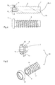
Fig. 4 eine Knochenschraube nach einer Ausführungsform in einer Seiten- und einer Schnittansicht; -
Fig. 5 eine Knochenschraube nach einer anderen Ausführungsform in einer Seiten- und einer Schnittansicht; -
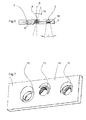
Fig. 6 eine Implantatplatte nach der Erfindung in einer Schnittansicht; und -
Fig. 7 die Implantatplatte derFigur 6 in einer perspektivischen Darstellung. - Die
Figur 1 zeigt ein System nach der Erfindung, das eine Implantatplatte 1 und zwei Knochenschrauben 2a, b aufweist. Die Implantatplatte 1 weist drei Durchgangsöffnungen 3, 4, 5 auf, die zur Aufnahme einer Knochenschraube 2, 20 bestimmt sind. In die Durchgangsöffnungen 3 und 5 ist jeweils eine Knochenschraube 2a bzw. 2b eingebracht, während die Durchgangsöffnung 4 leer ist. - Die Knochenschraube 2a ist in
Figur 2 zusammen mit der Implantatplatte 1 im Schnitt im Detail dargestellt. Die Knochenschraube 2b ist inFigur 3 zusammen mit der Implantatplatte 1 im Schnitt im Detail dargestellt. Aus einem Vergleich derFiguren 2 und 3 geht hervor, dass die Knochenschrauben 2a und 2b mit unterschiedlichen Einschraubwinkeln relativ zur Normalen 6 der Implantatplatte 1 positioniert sind. - Die Knochenschraube 2a weist einen Schaft 7 auf (siehe auch
Fig. 4 ), der mit einem Knochengewinde 8 versehen ist. Endseitig weist die Knochenschraube 2a einen Schraubenkopf 9 auf. Das Knochengewinde 8 läuft bis kurz unterhalb des Schraubenkopfs 9. In dessen vom Schaft 7 abgewandten Oberseite ist eine Aufnahme 10 für ein Schraubwerkzeug ausgebildet, im gezeigten Beispiel eine Innensechskantaufnahme für einen Sechskantschlüssel. In der dem Schaft 7 zugewandten Unterseite des Schraubenkopfs 9 ist eine nutförmige Vertiefung 11 ausgebildet. Diese läuft in Umfangsrichtung um, so dass sie eine ringförmige Nut bildet, die in der Unterseite des Schraubenkopfs 9 um den Schaft 7 herum verläuft. Die in radialer Richtung äußere Nutflanke 12 der Vertiefung 11 ist kugelsegmentartig, insbesondere konkav, geformt, wobei der Radius r des Kugelsegments von der Mittelachse 13 der Knochenschraube 2a bzw. des Schafts 7 zur Oberfläche der Nutflanke 12 verläuft. Die Knochenschraube 2b ist entsprechend ausgebildet. - An der Implantatplatte 1 ist an deren dem Knochen abgewandten Seite 14 um jede der Durchgangsöffnungen 3, 4, 5 ein die jeweilige Durchgangsöffnung ringförmig umgebender Kragen 15 ausgebildet. Der Kragen 15 weist eine der jeweiligen Durchgangsöffnung 3, 4, 5 zugewandte, also in radialer Richtung innere Kragenflanke 16 und eine der jeweiligen Durchgangsöffnung 3, 4, 5 abgewandte, also in radialer Richtung äußere Kragenflanke 17 auf. Die äußere Kragenflanke 17 ist kugelsegmentartig, insbesondere konvex, geformt, wobei der Radius R des Kugelsegments von der Achse 19 der Durchgangsöffnung 3, 4, 5 zur Oberfläche der Kragenflanke 17 verläuft. Genauer gesagt, befindet sich der Mittelpunkt des Kugelsegments in Dickenrichtung der Platte innerhalb der Implantatplatte, so dass der Schwenkpunkt der Knochenschraube 2a, b sich innerhalb der Implantatplatte befindet. Der Radiusmittelpunkt des Kugelsegments kann sich auch etwas außerhalb der Implantatplatte 1 befinden. Die beiden Radien r (der Nutflanke 12) und R (der Kragenflanke 17) können gleich groß sein, in welchem Fall - wie gezeigt - die beiden kugelsegmentartigen Flächen von Nutflanke 12 und Kragenflanke 17 vollflächig aneinander anliegen. Der Radius R der Kragenflanke 17 kann allerdings auch kleiner als der Radius r der Nutflanke 12 sein, in welchem Fall eine linienförmige Anlage von Nut- und Kragenflanke mit entsprechend größerer Flächenpressung erzielt wird und die Knochenschraube universeller verwendbar ist. Der Kragen 15 ist von einem ringförmigen Einstich 18 umgeben und wird durch Einbringen des Einstichs 18 in die Seite 14 der Implantatplatte 1 hergestellt.
- Wie insbesondere aus
Figur 6 hervorgeht, sind die Durchgangsöffnungen 3, 4, 5 jeweils mit einem Innengewinde versehen. Die Durchgangsöffnung 3 ist beispielhaft mit einem geraden Gewinde versehen, während die Innengewinde der Durchgangsöffnungen 4 und 5 konisch mit unterschiedlichen Konuswinkeln ausgebildet sind. Insbesondere eine relativ dünne Implantatplatte kann mit einem kurzstreckigen geraden Gewinde versehen sein, während bei einer dickeren Implantatplatte ein langstreckiges konisches Gewinde vorgesehen sein sollte. Wie in derFig. 6 gezeigt, öffnet sich das konische Innengewinde zu der Seite hin, die mit dem Knochen verbunden wird, bzw. zu der der Kragenflanke 17 gegenüberliegenden oder abgewandten Seite der Implantatplatte 1 hin. - Die
Figuren 6 und 7 zeigen des Weiteren, dass die jeweiligen Durchtrittswinkel der Durchgangsöffnungen 3, 4, 5, also die Winkel zwischen der Längsachse 19 der entsprechenden Durchgangsöffnung relativ zur Normalen 6 der Implantatplatte 1, unterschiedlich sind. Während die Durchgangsöffnungen 3 und 5 in Richtung der Normalen eingebracht ist, ist die Durchgangsöffnung 4 in einem Winkel schräg zur Normalen geneigt. Die Innengewinde der Durchgangsöffnungen 3, 4, 5 weisen gegenüber dem Knochengewinde 8 der Knochenschrauben 2a, b ein gewisses Winkelspiel auf, so dass die entsprechende Knochenschraube 2 ohne Spanbildung in einem Winkel schräg zur Längsachse der jeweiligen Durchgangsöffnung eingeschraubt werden kann. Dieses Winkelspiel wird durch die konische Gewindeform der Innengewinde der Durchgangsöffnungen 4 und 5 erzielt. Eine andere zusätzliche oder alternative Möglichkeit zum schrägen Einschrauben wird durch die geneigte Längsachse der Durchgangsöffnungen erzielt. - Nach der Erfindung steht das Knochengewinde 8 sowohl mit dem (in den Figuren nicht dargestellten) Knochen als auch mit dem Innengewinde der jeweiligen Durchgangsöffnung 3, 4, 5 in Einriff. Um einen sicheren Halt der Knochenschraube 2 in dem Innengewinde gewährleisten zu können, ist es von Vorteil, wenn das Knochengewinde 8 möglichst nahe an den Schraubenkopf 9 heranreicht, da dann bei einem vollständigen Eindrehen der Knochenschraube ausreichend Gewindelänge zur Verfügung steht, um mit dem Innengewinde in Eingriff zu stehen. Aus fertigungstechnischen Gründen ist es jedoch schwierig, wenn nicht unmöglich, das Knochengewinde 8 bei der in den
Figuren 1, 2, 3 und4 dargestellten Ausführungsform der Knochenschraube 2 bis nahe an den Schraubenkopf 9 zu führen. Abhilfe schafft hier die in derFigur 5 dargestellte Ausführungsform in Form der Knochenschraube 20. Während bei der inFigur 4 dargestellten Knochenschraube 2 deren Schaft 7 und Kopf 9 einstückig ausgebildet sind, ist die Knochenschraube 20 derFigur 5 zweiteilig aufgebaut. Sie weist den Schaft 7 auf, der endseitig zu einem Teil des Schraubenkopfs 9 aufgeweitet ist. Der schaftseitige Bereich des Schraubenkopfs 9 ist durch einen auf den Schaft 7 aufgepressten Ring 21 gebildet. Dieser weist eine geneigte, zum Schaft 7 gerichtete Fläche 22 auf, die zusammen mit dem Schaft 7 die nutförmige Vertiefung 11 bildet. Die Fläche 22 bildet dabei die äußere Nutflanke aus. Die Knochenschraube 20 wird hergestellt, indem zunächst das Knochengewinde 8 ausgebildet wird und nachfolgend der Ring 21 im Bereich des Schraubenkopfs 9 auf den Schaft aufgepresst wird.
Claims (14)
- Knochenschraube (2, 20) zum winkelvariablen Verschrauben einer Implantatplatte (1) mit einem Knochen, insbesondere einer Implantatplatte (1) nach einem der Ansprüche 7 bis 13, wobei
die Knochenschraube (2, 20) einen Schaft (7) mit einem Knochengewinde (8) und an einem Ende des Schafts (7) einen Schraubenkopf (9) aufweist,
in dem Schraubenkopf (9) in dessen zum Schaft (7) weisender Unterseite eine in Umfangsrichtung umlaufende nutförmige Vertiefung (11) ausgebildet ist, und
die nutförmige Vertiefung (11) eine Nutflanke (12, 22) aufweist, die zum Verklemmen, Verspannen oder Verblocken mit einer Implantatplatte (1) bestimmt ist. - Knochenschraube nach Anspruch 1, dadurch gekennzeichnet, dass die zum Verklemmen oder Verblocken bestimmte Nutflanke (12, 22) die in radialer Richtung äußere Nutflanke der Vertiefung (11) ist.
- Knochenschraube nach Anspruch 1 oder 2, dadurch gekennzeichnet, dass die zum Verklemmen oder Verblocken bestimmte Nutflanke (12, 22) in axialer Richtung gegenüber der Längsachse (13) des Schaftes (7) um einen Winkel α geneigt ist, wobei α vorzugsweise in einem Bereich zwischen 30° und 50°, bevorzugter zwischen 35° und 45° liegt.
- Knochenschraube nach Anspruch 1 oder 2, dadurch gekennzeichnet, dass die zum Verklemmen oder Verblocken bestimmte Nutflanke (12, 22) kugelsegmentförmig oder konkav mit einem Radius r ausgebildet ist.
- Knochenschraube nach einem der vorstehenden Ansprüche, dadurch gekennzeichnet, dass der Schraubenkopf (9) zumindest teilweise durch einen am kopfseitigen Ende des Schaftes (7) angeordneten, den Schaft (7) radial umgebenden, insbesondere zum Schaft (7) separaten, Ring (21) ausgebildet ist.
- Knochenschraube nach Anspruch 5, dadurch gekennzeichnet, dass der Ring (21) zumindest die radial äußere Flanke (22) der nutförmigen Vertiefung (11) ausbildet oder dass die nutförmige Vertiefung (11) in dem Ring (21) ausgebildet ist.
- Implantatplatte (1) zum winkelvariablen Verschrauben einer Knochenschraube (2, 20) mit einem Knochen, insbesondere einer Knochenschraube (2, 20) nach einem der Ansprüche 1 bis 6, wobei
die Implantatplatte (1) wenigstens eine Durchgangsöffnung (3, 4, 5) zur Aufnahme der Knochenschraube (2, 20) aufweist,
die Durchgangsöffnung (3, 4, 5) auf der der zur Anlage am Knochen bestimmten Seite gegenüberliegenden Seite (14) der Implantatplatte (1) von einem in Umfangsrichtung umlaufenden und in axialer Richtung vorstehenden Kragen (15) umgeben ist, und
der Kragen (15) eine Kragenflanke (17) aufweist, die zum Verklemmen, Verspannen oder Verblocken mit der Knochenschraube (2, 20) bestimmt ist. - Implantatplatte nach Anspruch 7, dadurch gekennzeichnet, dass die zum Verklemmen oder Verblocken bestimmte Kragenflanke (17) die auf der der Durchgangsöffnung (3, 4, 5) abgewandten Seite liegenden Kragenflanke (17) ist.
- Implantatplatte nach Anspruch 7 oder 8, dadurch gekennzeichnet, dass die Kragenflanke (17) in axialer Richtung gegenüber der Längsachse (19) der Durchgangsöffnung (3, 4, 5) um einen Winkel α geneigt ist, wobei α vorzugsweise in einem Bereich zwischen 20° und 40°, bevorzugter zwischen 25° und 35° liegt.
- Implantatplatte nach einem der vorhergehenden Ansprüche 7 bis 9,
dadurch gekennzeichnet, dass die Kragenflanke (17) kugelsegmentförmig oder konvex mit einem Radius R ausgebildet ist. - Implantatplatte nach einem der vorhergehenden Ansprüche 7 bis 10,
dadurch gekennzeichnet, dass in der Durchgangsöffnung (3, 4, 5) ein Innengewinde ausgebildet ist. - Implantatplatte nach einem der vorhergehenden Ansprüche 7 bis 11,
dadurch gekennzeichnet, dass in der Durchgangsöffnung (3, 4, 5) ein kegelförmiges Innengewinde ausgebildet ist, mit einem bevorzugten Kegelwinkel γ von 16° oder 18°. - Implantatplatte nach einem der vorhergehenden Ansprüche 7 bis 12,
dadurch gekennzeichnet, dass die Achse (19) wenigstens einer Durchgangsöffnung (3, 4, 5) gegenüber der Normalen (6) der Implantatplatte (1) um einen Winkel β geneigt ist, wobei der Winkel β vorzugsweise in einem Bereich zwischen 0° und 10°, bevorzugter zwischen 2° und 8,2° liegt. - System aus wenigstens einer Knochenschraube (2, 20) nach einem der Ansprüche 1 bis 6 und einer Implantatplatte (1) nach einem der Ansprüche 7 bis 13.
Applications Claiming Priority (1)
| Application Number | Priority Date | Filing Date | Title |
|---|---|---|---|
| DE102013109569.0A DE102013109569A1 (de) | 2013-09-02 | 2013-09-02 | Knochenschrauben, Implantatplatte und System daraus |
Publications (2)
| Publication Number | Publication Date |
|---|---|
| EP2842504A1 true EP2842504A1 (de) | 2015-03-04 |
| EP2842504B1 EP2842504B1 (de) | 2018-07-11 |
Family
ID=51485478
Family Applications (1)
| Application Number | Title | Priority Date | Filing Date |
|---|---|---|---|
| EP14182914.3A Active EP2842504B1 (de) | 2013-09-02 | 2014-08-29 | Knochenschraube, Implantatplatte und System daraus |
Country Status (3)
| Country | Link |
|---|---|
| EP (1) | EP2842504B1 (de) |
| JP (1) | JP6474567B2 (de) |
| DE (1) | DE102013109569A1 (de) |
Citations (9)
| Publication number | Priority date | Publication date | Assignee | Title |
|---|---|---|---|---|
| US20060009771A1 (en) | 2000-02-01 | 2006-01-12 | Orbay Jorge L | Bone stabilization system including plate having fixed-angle holes together with unidirectional locking screws and surgeon-directed locking screws |
| DE102005042766A1 (de) | 2005-07-13 | 2007-01-25 | Königsee Implantate und Instrumente zur Osteosynthese GmbH | Winkelstabil variable Verschraubung für eine Knochenplatte zur Osteosynthese und dergleichen Implantat |
| US20070233125A1 (en) * | 2006-03-17 | 2007-10-04 | Nexa Orthopedics, Inc. | Bone screw with selectively securable washer |
| US20090157123A1 (en) * | 2007-12-17 | 2009-06-18 | Andreas Appenzeller | Dynamic bone fixation element and method of using the same |
| WO2011085272A1 (en) | 2010-01-08 | 2011-07-14 | Biomet Manufacturing Corp. | Variable angle locking screw |
| US20110184415A1 (en) * | 2010-01-26 | 2011-07-28 | Westmark Medical, Llc | Bone screw retention mechanism |
| EP2364657A1 (de) * | 2010-03-08 | 2011-09-14 | Stryker Trauma SA | Système de fixation osseuse avec fils profilés incurvés |
| US20110313421A1 (en) * | 2010-06-17 | 2011-12-22 | Chris Sidebotham | Low profile medical locking plate and bone screw design for bone fractures |
| EP2308403B1 (de) | 2009-10-12 | 2013-03-27 | NORMED Medizin-Technik GmbH | Knochenschraube sowie System |
Family Cites Families (2)
| Publication number | Priority date | Publication date | Assignee | Title |
|---|---|---|---|---|
| DE102005032026B3 (de) * | 2005-07-08 | 2006-12-14 | Stryker Leibinger Gmbh & Co. Kg | Osteosyntheseplatte mit schräg zur Plattenebene verlaufenden Durchgangsöffnungen |
| DE102009060396B4 (de) * | 2009-12-22 | 2017-04-13 | Bernhard Clasbrummel | Knochenplatte mit Vorrichtung zur winkelstabilen Schraubenfixation und Schrauben hierfür |
-
2013
- 2013-09-02 DE DE102013109569.0A patent/DE102013109569A1/de not_active Withdrawn
-
2014
- 2014-08-29 EP EP14182914.3A patent/EP2842504B1/de active Active
- 2014-09-01 JP JP2014177147A patent/JP6474567B2/ja active Active
Patent Citations (9)
| Publication number | Priority date | Publication date | Assignee | Title |
|---|---|---|---|---|
| US20060009771A1 (en) | 2000-02-01 | 2006-01-12 | Orbay Jorge L | Bone stabilization system including plate having fixed-angle holes together with unidirectional locking screws and surgeon-directed locking screws |
| DE102005042766A1 (de) | 2005-07-13 | 2007-01-25 | Königsee Implantate und Instrumente zur Osteosynthese GmbH | Winkelstabil variable Verschraubung für eine Knochenplatte zur Osteosynthese und dergleichen Implantat |
| US20070233125A1 (en) * | 2006-03-17 | 2007-10-04 | Nexa Orthopedics, Inc. | Bone screw with selectively securable washer |
| US20090157123A1 (en) * | 2007-12-17 | 2009-06-18 | Andreas Appenzeller | Dynamic bone fixation element and method of using the same |
| EP2308403B1 (de) | 2009-10-12 | 2013-03-27 | NORMED Medizin-Technik GmbH | Knochenschraube sowie System |
| WO2011085272A1 (en) | 2010-01-08 | 2011-07-14 | Biomet Manufacturing Corp. | Variable angle locking screw |
| US20110184415A1 (en) * | 2010-01-26 | 2011-07-28 | Westmark Medical, Llc | Bone screw retention mechanism |
| EP2364657A1 (de) * | 2010-03-08 | 2011-09-14 | Stryker Trauma SA | Système de fixation osseuse avec fils profilés incurvés |
| US20110313421A1 (en) * | 2010-06-17 | 2011-12-22 | Chris Sidebotham | Low profile medical locking plate and bone screw design for bone fractures |
Also Published As
| Publication number | Publication date |
|---|---|
| JP6474567B2 (ja) | 2019-02-27 |
| JP2015061596A (ja) | 2015-04-02 |
| DE102013109569A1 (de) | 2015-03-05 |
| EP2842504B1 (de) | 2018-07-11 |
Similar Documents
| Publication | Publication Date | Title |
|---|---|---|
| EP2416720B1 (de) | Vorrichtung zur winkelstabilen fixation und kompression einer bruchstelle bzw. osteotomie an einem knochen | |
| DE102005042766B4 (de) | Plattenloch einer Knochenplatte für die Osteosynthese | |
| EP1608278B1 (de) | Aufnahme für ein verblockungselement und verblockungselement | |
| EP1457161B1 (de) | Verankerungselement zur Verwendung in der Wirbelsäulen- oder Knochenchirurgie und Verfahren zu seiner Herstellung | |
| EP2844169B1 (de) | Knochenplattensystem für osteosynthese | |
| EP3267913A1 (de) | Knochenplatte mit einer knochenschraube | |
| EP1622527A1 (de) | Implantat mit einem fixierkörper für eine knochenschraube | |
| EP3100691B1 (de) | Uniplanares knochenverankerungselement | |
| DE102005004841B4 (de) | Osteosyntheseplatte mit einer Vielzahl von Bohrungen zur Aufnahme von Knochenschrauben | |
| EP3261566B1 (de) | Knochenplatte und operationsset zum fixieren von knochenfragmenten | |
| DE102009021597A1 (de) | Schnellspannmutter und Schnellspannsystem | |
| EP3209229B1 (de) | Vorrichtung zum befestigen eines stabs an einem knochen | |
| EP2701622B1 (de) | Verschlusseinrichtung für kanülierte knochenschrauben | |
| EP2842504B1 (de) | Knochenschraube, Implantatplatte und System daraus | |
| DE102004056091B4 (de) | Orthopädische Fixationsvorrichtung und orthopädisches Fixationssystem | |
| EP3157449B1 (de) | Pedikelschraube mit einschraubhilfe | |
| DE102005014546B4 (de) | Großfragmentplatte und Adapter für eine Großfragmentplatte | |
| EP3610988B1 (de) | Pressvorrichtung mit zentrierter bolzenfixierung | |
| WO2008003313A2 (de) | Osteosynthesisches fixationssystem | |
| EP3856059B1 (de) | Fixationssystem für knochen | |
| CH717204A2 (de) | Set mit Schraube und Werkzeug. | |
| DE102014226493B4 (de) | Verbindungselement zum Fixieren von mindestens zwei Knochen oder Knochenfragmenten eines Lebewesens | |
| EP3228881A1 (de) | Bausatz zum verbinden von bauteilen | |
| DE102015012909A1 (de) | Vorrichtung zum Befestigen eines Stabs an einem Knochen | |
| EP3484391A1 (de) | Polyaxiales knochenfixationssystem |
Legal Events
| Date | Code | Title | Description |
|---|---|---|---|
| 17P | Request for examination filed |
Effective date: 20140829 |
|
| AK | Designated contracting states |
Kind code of ref document: A1 Designated state(s): AL AT BE BG CH CY CZ DE DK EE ES FI FR GB GR HR HU IE IS IT LI LT LU LV MC MK MT NL NO PL PT RO RS SE SI SK SM TR |
|
| AX | Request for extension of the european patent |
Extension state: BA ME |
|
| PUAI | Public reference made under article 153(3) epc to a published international application that has entered the european phase |
Free format text: ORIGINAL CODE: 0009012 |
|
| R17P | Request for examination filed (corrected) |
Effective date: 20150904 |
|
| RBV | Designated contracting states (corrected) |
Designated state(s): AL AT BE BG CH CY CZ DE DK EE ES FI FR GB GR HR HU IE IS IT LI LT LU LV MC MK MT NL NO PL PT RO RS SE SI SK SM TR |
|
| GRAP | Despatch of communication of intention to grant a patent |
Free format text: ORIGINAL CODE: EPIDOSNIGR1 |
|
| INTG | Intention to grant announced |
Effective date: 20180122 |
|
| GRAS | Grant fee paid |
Free format text: ORIGINAL CODE: EPIDOSNIGR3 |
|
| GRAA | (expected) grant |
Free format text: ORIGINAL CODE: 0009210 |
|
| AK | Designated contracting states |
Kind code of ref document: B1 Designated state(s): AL AT BE BG CH CY CZ DE DK EE ES FI FR GB GR HR HU IE IS IT LI LT LU LV MC MK MT NL NO PL PT RO RS SE SI SK SM TR |
|
| REG | Reference to a national code |
Ref country code: GB Ref legal event code: FG4D Free format text: NOT ENGLISH |
|
| REG | Reference to a national code |
Ref country code: CH Ref legal event code: EP |
|
| REG | Reference to a national code |
Ref country code: AT Ref legal event code: REF Ref document number: 1016098 Country of ref document: AT Kind code of ref document: T Effective date: 20180715 |
|
| REG | Reference to a national code |
Ref country code: IE Ref legal event code: FG4D Free format text: LANGUAGE OF EP DOCUMENT: GERMAN |
|
| REG | Reference to a national code |
Ref country code: DE Ref legal event code: R096 Ref document number: 502014008789 Country of ref document: DE |
|
| REG | Reference to a national code |
Ref country code: FR Ref legal event code: PLFP Year of fee payment: 5 |
|
| REG | Reference to a national code |
Ref country code: NL Ref legal event code: MP Effective date: 20180711 |
|
| REG | Reference to a national code |
Ref country code: LT Ref legal event code: MG4D |
|
| PG25 | Lapsed in a contracting state [announced via postgrant information from national office to epo] |
Ref country code: NL Free format text: LAPSE BECAUSE OF FAILURE TO SUBMIT A TRANSLATION OF THE DESCRIPTION OR TO PAY THE FEE WITHIN THE PRESCRIBED TIME-LIMIT Effective date: 20180711 |
|
| PG25 | Lapsed in a contracting state [announced via postgrant information from national office to epo] |
Ref country code: NO Free format text: LAPSE BECAUSE OF FAILURE TO SUBMIT A TRANSLATION OF THE DESCRIPTION OR TO PAY THE FEE WITHIN THE PRESCRIBED TIME-LIMIT Effective date: 20181011 Ref country code: BG Free format text: LAPSE BECAUSE OF FAILURE TO SUBMIT A TRANSLATION OF THE DESCRIPTION OR TO PAY THE FEE WITHIN THE PRESCRIBED TIME-LIMIT Effective date: 20181011 Ref country code: PL Free format text: LAPSE BECAUSE OF FAILURE TO SUBMIT A TRANSLATION OF THE DESCRIPTION OR TO PAY THE FEE WITHIN THE PRESCRIBED TIME-LIMIT Effective date: 20180711 Ref country code: LT Free format text: LAPSE BECAUSE OF FAILURE TO SUBMIT A TRANSLATION OF THE DESCRIPTION OR TO PAY THE FEE WITHIN THE PRESCRIBED TIME-LIMIT Effective date: 20180711 Ref country code: IS Free format text: LAPSE BECAUSE OF FAILURE TO SUBMIT A TRANSLATION OF THE DESCRIPTION OR TO PAY THE FEE WITHIN THE PRESCRIBED TIME-LIMIT Effective date: 20181111 Ref country code: GR Free format text: LAPSE BECAUSE OF FAILURE TO SUBMIT A TRANSLATION OF THE DESCRIPTION OR TO PAY THE FEE WITHIN THE PRESCRIBED TIME-LIMIT Effective date: 20181012 Ref country code: RS Free format text: LAPSE BECAUSE OF FAILURE TO SUBMIT A TRANSLATION OF THE DESCRIPTION OR TO PAY THE FEE WITHIN THE PRESCRIBED TIME-LIMIT Effective date: 20180711 Ref country code: FI Free format text: LAPSE BECAUSE OF FAILURE TO SUBMIT A TRANSLATION OF THE DESCRIPTION OR TO PAY THE FEE WITHIN THE PRESCRIBED TIME-LIMIT Effective date: 20180711 Ref country code: SE Free format text: LAPSE BECAUSE OF FAILURE TO SUBMIT A TRANSLATION OF THE DESCRIPTION OR TO PAY THE FEE WITHIN THE PRESCRIBED TIME-LIMIT Effective date: 20180711 |
|
| PG25 | Lapsed in a contracting state [announced via postgrant information from national office to epo] |
Ref country code: AL Free format text: LAPSE BECAUSE OF FAILURE TO SUBMIT A TRANSLATION OF THE DESCRIPTION OR TO PAY THE FEE WITHIN THE PRESCRIBED TIME-LIMIT Effective date: 20180711 Ref country code: HR Free format text: LAPSE BECAUSE OF FAILURE TO SUBMIT A TRANSLATION OF THE DESCRIPTION OR TO PAY THE FEE WITHIN THE PRESCRIBED TIME-LIMIT Effective date: 20180711 Ref country code: LV Free format text: LAPSE BECAUSE OF FAILURE TO SUBMIT A TRANSLATION OF THE DESCRIPTION OR TO PAY THE FEE WITHIN THE PRESCRIBED TIME-LIMIT Effective date: 20180711 Ref country code: ES Free format text: LAPSE BECAUSE OF FAILURE TO SUBMIT A TRANSLATION OF THE DESCRIPTION OR TO PAY THE FEE WITHIN THE PRESCRIBED TIME-LIMIT Effective date: 20180711 |
|
| REG | Reference to a national code |
Ref country code: DE Ref legal event code: R097 Ref document number: 502014008789 Country of ref document: DE |
|
| PG25 | Lapsed in a contracting state [announced via postgrant information from national office to epo] |
Ref country code: LU Free format text: LAPSE BECAUSE OF NON-PAYMENT OF DUE FEES Effective date: 20180829 Ref country code: MC Free format text: LAPSE BECAUSE OF FAILURE TO SUBMIT A TRANSLATION OF THE DESCRIPTION OR TO PAY THE FEE WITHIN THE PRESCRIBED TIME-LIMIT Effective date: 20180711 Ref country code: IT Free format text: LAPSE BECAUSE OF FAILURE TO SUBMIT A TRANSLATION OF THE DESCRIPTION OR TO PAY THE FEE WITHIN THE PRESCRIBED TIME-LIMIT Effective date: 20180711 Ref country code: CZ Free format text: LAPSE BECAUSE OF FAILURE TO SUBMIT A TRANSLATION OF THE DESCRIPTION OR TO PAY THE FEE WITHIN THE PRESCRIBED TIME-LIMIT Effective date: 20180711 Ref country code: EE Free format text: LAPSE BECAUSE OF FAILURE TO SUBMIT A TRANSLATION OF THE DESCRIPTION OR TO PAY THE FEE WITHIN THE PRESCRIBED TIME-LIMIT Effective date: 20180711 Ref country code: RO Free format text: LAPSE BECAUSE OF FAILURE TO SUBMIT A TRANSLATION OF THE DESCRIPTION OR TO PAY THE FEE WITHIN THE PRESCRIBED TIME-LIMIT Effective date: 20180711 |
|
| REG | Reference to a national code |
Ref country code: BE Ref legal event code: MM Effective date: 20180831 |
|
| PLBE | No opposition filed within time limit |
Free format text: ORIGINAL CODE: 0009261 |
|
| STAA | Information on the status of an ep patent application or granted ep patent |
Free format text: STATUS: NO OPPOSITION FILED WITHIN TIME LIMIT |
|
| PG25 | Lapsed in a contracting state [announced via postgrant information from national office to epo] |
Ref country code: SM Free format text: LAPSE BECAUSE OF FAILURE TO SUBMIT A TRANSLATION OF THE DESCRIPTION OR TO PAY THE FEE WITHIN THE PRESCRIBED TIME-LIMIT Effective date: 20180711 Ref country code: DK Free format text: LAPSE BECAUSE OF FAILURE TO SUBMIT A TRANSLATION OF THE DESCRIPTION OR TO PAY THE FEE WITHIN THE PRESCRIBED TIME-LIMIT Effective date: 20180711 Ref country code: SK Free format text: LAPSE BECAUSE OF FAILURE TO SUBMIT A TRANSLATION OF THE DESCRIPTION OR TO PAY THE FEE WITHIN THE PRESCRIBED TIME-LIMIT Effective date: 20180711 |
|
| 26N | No opposition filed |
Effective date: 20190412 |
|
| PG25 | Lapsed in a contracting state [announced via postgrant information from national office to epo] |
Ref country code: SI Free format text: LAPSE BECAUSE OF FAILURE TO SUBMIT A TRANSLATION OF THE DESCRIPTION OR TO PAY THE FEE WITHIN THE PRESCRIBED TIME-LIMIT Effective date: 20180711 Ref country code: BE Free format text: LAPSE BECAUSE OF NON-PAYMENT OF DUE FEES Effective date: 20180831 |
|
| PG25 | Lapsed in a contracting state [announced via postgrant information from national office to epo] |
Ref country code: MT Free format text: LAPSE BECAUSE OF FAILURE TO SUBMIT A TRANSLATION OF THE DESCRIPTION OR TO PAY THE FEE WITHIN THE PRESCRIBED TIME-LIMIT Effective date: 20180711 |
|
| PG25 | Lapsed in a contracting state [announced via postgrant information from national office to epo] |
Ref country code: TR Free format text: LAPSE BECAUSE OF FAILURE TO SUBMIT A TRANSLATION OF THE DESCRIPTION OR TO PAY THE FEE WITHIN THE PRESCRIBED TIME-LIMIT Effective date: 20180711 |
|
| PG25 | Lapsed in a contracting state [announced via postgrant information from national office to epo] |
Ref country code: HU Free format text: LAPSE BECAUSE OF FAILURE TO SUBMIT A TRANSLATION OF THE DESCRIPTION OR TO PAY THE FEE WITHIN THE PRESCRIBED TIME-LIMIT; INVALID AB INITIO Effective date: 20140829 Ref country code: PT Free format text: LAPSE BECAUSE OF FAILURE TO SUBMIT A TRANSLATION OF THE DESCRIPTION OR TO PAY THE FEE WITHIN THE PRESCRIBED TIME-LIMIT Effective date: 20180711 |
|
| PG25 | Lapsed in a contracting state [announced via postgrant information from national office to epo] |
Ref country code: CY Free format text: LAPSE BECAUSE OF FAILURE TO SUBMIT A TRANSLATION OF THE DESCRIPTION OR TO PAY THE FEE WITHIN THE PRESCRIBED TIME-LIMIT Effective date: 20180711 Ref country code: MK Free format text: LAPSE BECAUSE OF NON-PAYMENT OF DUE FEES Effective date: 20180711 Ref country code: IE Free format text: LAPSE BECAUSE OF NON-PAYMENT OF DUE FEES Effective date: 20180829 |
|
| REG | Reference to a national code |
Ref country code: AT Ref legal event code: MM01 Ref document number: 1016098 Country of ref document: AT Kind code of ref document: T Effective date: 20190829 |
|
| PG25 | Lapsed in a contracting state [announced via postgrant information from national office to epo] |
Ref country code: AT Free format text: LAPSE BECAUSE OF NON-PAYMENT OF DUE FEES Effective date: 20190829 |
|
| P01 | Opt-out of the competence of the unified patent court (upc) registered |
Effective date: 20230804 |
|
| PGFP | Annual fee paid to national office [announced via postgrant information from national office to epo] |
Ref country code: DE Payment date: 20250819 Year of fee payment: 12 |
|
| PGFP | Annual fee paid to national office [announced via postgrant information from national office to epo] |
Ref country code: GB Payment date: 20250822 Year of fee payment: 12 |
|
| PGFP | Annual fee paid to national office [announced via postgrant information from national office to epo] |
Ref country code: FR Payment date: 20250827 Year of fee payment: 12 |
|
| PGFP | Annual fee paid to national office [announced via postgrant information from national office to epo] |
Ref country code: CH Payment date: 20250901 Year of fee payment: 12 |