EP2842481A1 - Hydrogel-Implantat für Sensorik von Metaboliten in Körpergewebe - Google Patents
Hydrogel-Implantat für Sensorik von Metaboliten in Körpergewebe Download PDFInfo
- Publication number
- EP2842481A1 EP2842481A1 EP14186223.5A EP14186223A EP2842481A1 EP 2842481 A1 EP2842481 A1 EP 2842481A1 EP 14186223 A EP14186223 A EP 14186223A EP 2842481 A1 EP2842481 A1 EP 2842481A1
- Authority
- EP
- European Patent Office
- Prior art keywords
- hydrogel
- implant
- sensor
- matrix
- analyte
- Prior art date
- Legal status (The legal status is an assumption and is not a legal conclusion. Google has not performed a legal analysis and makes no representation as to the accuracy of the status listed.)
- Granted
Links
- 239000000017 hydrogel Substances 0.000 title claims abstract description 95
- 239000007943 implant Substances 0.000 title claims abstract description 76
- 239000002207 metabolite Substances 0.000 title description 5
- 239000011159 matrix material Substances 0.000 claims abstract description 72
- 239000002245 particle Substances 0.000 claims abstract description 69
- 239000012491 analyte Substances 0.000 claims abstract description 31
- 239000000463 material Substances 0.000 claims abstract description 30
- 239000012530 fluid Substances 0.000 claims abstract description 13
- 210000001124 body fluid Anatomy 0.000 claims abstract description 12
- 239000010839 body fluid Substances 0.000 claims abstract description 12
- 229920000615 alginic acid Polymers 0.000 claims description 25
- 235000010443 alginic acid Nutrition 0.000 claims description 25
- FHVDTGUDJYJELY-UHFFFAOYSA-N 6-{[2-carboxy-4,5-dihydroxy-6-(phosphanyloxy)oxan-3-yl]oxy}-4,5-dihydroxy-3-phosphanyloxane-2-carboxylic acid Chemical compound O1C(C(O)=O)C(P)C(O)C(O)C1OC1C(C(O)=O)OC(OP)C(O)C1O FHVDTGUDJYJELY-UHFFFAOYSA-N 0.000 claims description 22
- 229940072056 alginate Drugs 0.000 claims description 22
- WQZGKKKJIJFFOK-GASJEMHNSA-N Glucose Natural products OC[C@H]1OC(O)[C@H](O)[C@@H](O)[C@@H]1O WQZGKKKJIJFFOK-GASJEMHNSA-N 0.000 claims description 17
- 239000008103 glucose Substances 0.000 claims description 17
- XLYOFNOQVPJJNP-UHFFFAOYSA-N water Substances O XLYOFNOQVPJJNP-UHFFFAOYSA-N 0.000 claims description 17
- 229920000642 polymer Polymers 0.000 claims description 15
- 239000012528 membrane Substances 0.000 claims description 10
- 108090000623 proteins and genes Proteins 0.000 claims description 9
- 102000004169 proteins and genes Human genes 0.000 claims description 9
- 239000000126 substance Substances 0.000 claims description 9
- 229920001282 polysaccharide Polymers 0.000 claims description 7
- 239000005017 polysaccharide Substances 0.000 claims description 7
- -1 boric acid ester Chemical class 0.000 claims description 6
- 102000005548 Hexokinase Human genes 0.000 claims description 4
- 108700040460 Hexokinases Proteins 0.000 claims description 4
- CERQOIWHTDAKMF-UHFFFAOYSA-N Methacrylic acid Chemical class CC(=C)C(O)=O CERQOIWHTDAKMF-UHFFFAOYSA-N 0.000 claims description 4
- 230000008859 change Effects 0.000 claims description 4
- 229920001577 copolymer Polymers 0.000 claims description 4
- 238000004132 cross linking Methods 0.000 claims description 4
- 238000004020 luminiscence type Methods 0.000 claims description 4
- XDIYNQZUNSSENW-NUVHGKSTSA-N (2r,3s,4s,5r)-2,3,4,5,6-pentahydroxyhexanal;(2r,3s,4r,5r)-2,3,4,5,6-pentahydroxyhexanal Chemical compound OC[C@@H](O)[C@H](O)[C@H](O)[C@@H](O)C=O.OC[C@@H](O)[C@@H](O)[C@H](O)[C@@H](O)C=O XDIYNQZUNSSENW-NUVHGKSTSA-N 0.000 claims description 3
- NIXOWILDQLNWCW-UHFFFAOYSA-N acrylic acid group Chemical group C(C=C)(=O)O NIXOWILDQLNWCW-UHFFFAOYSA-N 0.000 claims description 3
- 238000009792 diffusion process Methods 0.000 claims description 3
- 108010090623 galactose binding protein Proteins 0.000 claims description 3
- 102000021529 galactose binding proteins Human genes 0.000 claims description 3
- 229920002338 polyhydroxyethylmethacrylate Polymers 0.000 claims description 3
- 238000006116 polymerization reaction Methods 0.000 claims description 3
- 229920002451 polyvinyl alcohol Polymers 0.000 claims description 3
- 230000008961 swelling Effects 0.000 claims description 3
- OMIGHNLMNHATMP-UHFFFAOYSA-N 2-hydroxyethyl prop-2-enoate Chemical compound OCCOC(=O)C=C OMIGHNLMNHATMP-UHFFFAOYSA-N 0.000 claims description 2
- WHNPOQXWAMXPTA-UHFFFAOYSA-N 3-methylbut-2-enamide Chemical compound CC(C)=CC(N)=O WHNPOQXWAMXPTA-UHFFFAOYSA-N 0.000 claims description 2
- 229920002134 Carboxymethyl cellulose Polymers 0.000 claims description 2
- 108010062580 Concanavalin A Proteins 0.000 claims description 2
- 108010050375 Glucose 1-Dehydrogenase Proteins 0.000 claims description 2
- 239000004372 Polyvinyl alcohol Substances 0.000 claims description 2
- 150000001252 acrylic acid derivatives Chemical class 0.000 claims description 2
- 239000004327 boric acid Substances 0.000 claims description 2
- 239000001768 carboxy methyl cellulose Substances 0.000 claims description 2
- 235000010948 carboxy methyl cellulose Nutrition 0.000 claims description 2
- 239000008112 carboxymethyl-cellulose Substances 0.000 claims description 2
- 239000012634 fragment Substances 0.000 claims description 2
- 229920002401 polyacrylamide Polymers 0.000 claims description 2
- 150000004676 glycans Chemical class 0.000 claims 4
- 230000000704 physical effect Effects 0.000 claims 3
- 229920006037 cross link polymer Polymers 0.000 claims 1
- 230000002401 inhibitory effect Effects 0.000 claims 1
- 230000003993 interaction Effects 0.000 claims 1
- 238000000465 moulding Methods 0.000 description 13
- 239000000975 dye Substances 0.000 description 12
- 210000004379 membrane Anatomy 0.000 description 11
- 210000001519 tissue Anatomy 0.000 description 11
- 239000000243 solution Substances 0.000 description 10
- 239000008280 blood Substances 0.000 description 9
- 210000004369 blood Anatomy 0.000 description 9
- 238000001514 detection method Methods 0.000 description 9
- 239000007850 fluorescent dye Substances 0.000 description 9
- 238000000034 method Methods 0.000 description 9
- 239000011859 microparticle Substances 0.000 description 9
- 239000000203 mixture Substances 0.000 description 8
- 229920000867 polyelectrolyte Polymers 0.000 description 8
- 239000008351 acetate buffer Substances 0.000 description 7
- 229920002307 Dextran Polymers 0.000 description 6
- 239000006228 supernatant Substances 0.000 description 6
- 239000013543 active substance Substances 0.000 description 5
- 239000002105 nanoparticle Substances 0.000 description 5
- 239000004480 active ingredient Substances 0.000 description 4
- 239000011324 bead Substances 0.000 description 4
- 238000005266 casting Methods 0.000 description 4
- 238000000576 coating method Methods 0.000 description 4
- 230000000694 effects Effects 0.000 description 4
- 238000009472 formulation Methods 0.000 description 4
- 238000002513 implantation Methods 0.000 description 4
- 238000005259 measurement Methods 0.000 description 4
- 230000008569 process Effects 0.000 description 4
- YXFVVABEGXRONW-UHFFFAOYSA-N Toluene Chemical compound CC1=CC=CC=C1 YXFVVABEGXRONW-UHFFFAOYSA-N 0.000 description 3
- 239000011248 coating agent Substances 0.000 description 3
- 210000000795 conjunctiva Anatomy 0.000 description 3
- 238000005520 cutting process Methods 0.000 description 3
- 239000003814 drug Substances 0.000 description 3
- 229940079593 drug Drugs 0.000 description 3
- 125000000524 functional group Chemical group 0.000 description 3
- 239000011521 glass Substances 0.000 description 3
- 238000011068 loading method Methods 0.000 description 3
- 239000000178 monomer Substances 0.000 description 3
- 229920001467 poly(styrenesulfonates) Polymers 0.000 description 3
- 150000004804 polysaccharides Chemical class 0.000 description 3
- 229960002796 polystyrene sulfonate Drugs 0.000 description 3
- 239000011970 polystyrene sulfonate Substances 0.000 description 3
- 238000002360 preparation method Methods 0.000 description 3
- 239000002904 solvent Substances 0.000 description 3
- SMZOUWXMTYCWNB-UHFFFAOYSA-N 2-(2-methoxy-5-methylphenyl)ethanamine Chemical compound COC1=CC=C(C)C=C1CCN SMZOUWXMTYCWNB-UHFFFAOYSA-N 0.000 description 2
- 229930040373 Paraformaldehyde Natural products 0.000 description 2
- 229920002518 Polyallylamine hydrochloride Polymers 0.000 description 2
- 239000004743 Polypropylene Substances 0.000 description 2
- 230000009102 absorption Effects 0.000 description 2
- 238000010521 absorption reaction Methods 0.000 description 2
- 239000000654 additive Substances 0.000 description 2
- 210000001742 aqueous humor Anatomy 0.000 description 2
- 150000001875 compounds Chemical class 0.000 description 2
- 238000010276 construction Methods 0.000 description 2
- 230000007423 decrease Effects 0.000 description 2
- 239000008367 deionised water Substances 0.000 description 2
- 229910021641 deionized water Inorganic materials 0.000 description 2
- 238000013461 design Methods 0.000 description 2
- 238000011161 development Methods 0.000 description 2
- 230000018109 developmental process Effects 0.000 description 2
- 201000010099 disease Diseases 0.000 description 2
- 208000037265 diseases, disorders, signs and symptoms Diseases 0.000 description 2
- 238000009826 distribution Methods 0.000 description 2
- 238000005516 engineering process Methods 0.000 description 2
- 210000003722 extracellular fluid Anatomy 0.000 description 2
- NOESYZHRGYRDHS-UHFFFAOYSA-N insulin Chemical compound N1C(=O)C(NC(=O)C(CCC(N)=O)NC(=O)C(CCC(O)=O)NC(=O)C(C(C)C)NC(=O)C(NC(=O)CN)C(C)CC)CSSCC(C(NC(CO)C(=O)NC(CC(C)C)C(=O)NC(CC=2C=CC(O)=CC=2)C(=O)NC(CCC(N)=O)C(=O)NC(CC(C)C)C(=O)NC(CCC(O)=O)C(=O)NC(CC(N)=O)C(=O)NC(CC=2C=CC(O)=CC=2)C(=O)NC(CSSCC(NC(=O)C(C(C)C)NC(=O)C(CC(C)C)NC(=O)C(CC=2C=CC(O)=CC=2)NC(=O)C(CC(C)C)NC(=O)C(C)NC(=O)C(CCC(O)=O)NC(=O)C(C(C)C)NC(=O)C(CC(C)C)NC(=O)C(CC=2NC=NC=2)NC(=O)C(CO)NC(=O)CNC2=O)C(=O)NCC(=O)NC(CCC(O)=O)C(=O)NC(CCCNC(N)=N)C(=O)NCC(=O)NC(CC=3C=CC=CC=3)C(=O)NC(CC=3C=CC=CC=3)C(=O)NC(CC=3C=CC(O)=CC=3)C(=O)NC(C(C)O)C(=O)N3C(CCC3)C(=O)NC(CCCCN)C(=O)NC(C)C(O)=O)C(=O)NC(CC(N)=O)C(O)=O)=O)NC(=O)C(C(C)CC)NC(=O)C(CO)NC(=O)C(C(C)O)NC(=O)C1CSSCC2NC(=O)C(CC(C)C)NC(=O)C(NC(=O)C(CCC(N)=O)NC(=O)C(CC(N)=O)NC(=O)C(NC(=O)C(N)CC=1C=CC=CC=1)C(C)C)CC1=CN=CN1 NOESYZHRGYRDHS-UHFFFAOYSA-N 0.000 description 2
- 238000000608 laser ablation Methods 0.000 description 2
- 238000004519 manufacturing process Methods 0.000 description 2
- 239000008188 pellet Substances 0.000 description 2
- 229920003229 poly(methyl methacrylate) Polymers 0.000 description 2
- 239000004926 polymethyl methacrylate Substances 0.000 description 2
- 229920006324 polyoxymethylene Polymers 0.000 description 2
- 229920001155 polypropylene Polymers 0.000 description 2
- 235000019422 polyvinyl alcohol Nutrition 0.000 description 2
- 239000011148 porous material Substances 0.000 description 2
- 210000003786 sclera Anatomy 0.000 description 2
- 238000003756 stirring Methods 0.000 description 2
- 239000000725 suspension Substances 0.000 description 2
- UXVMQQNJUSDDNG-UHFFFAOYSA-L Calcium chloride Chemical compound [Cl-].[Cl-].[Ca+2] UXVMQQNJUSDDNG-UHFFFAOYSA-L 0.000 description 1
- 208000002177 Cataract Diseases 0.000 description 1
- AEMOLEFTQBMNLQ-BZINKQHNSA-N D-Guluronic Acid Chemical compound OC1O[C@H](C(O)=O)[C@H](O)[C@@H](O)[C@H]1O AEMOLEFTQBMNLQ-BZINKQHNSA-N 0.000 description 1
- 108010015776 Glucose oxidase Proteins 0.000 description 1
- 239000004366 Glucose oxidase Substances 0.000 description 1
- 102000004877 Insulin Human genes 0.000 description 1
- 108090001061 Insulin Proteins 0.000 description 1
- 206010025421 Macule Diseases 0.000 description 1
- 241001465754 Metazoa Species 0.000 description 1
- 239000004793 Polystyrene Substances 0.000 description 1
- VYPSYNLAJGMNEJ-UHFFFAOYSA-N Silicium dioxide Chemical compound O=[Si]=O VYPSYNLAJGMNEJ-UHFFFAOYSA-N 0.000 description 1
- 239000007983 Tris buffer Substances 0.000 description 1
- 239000002253 acid Substances 0.000 description 1
- 230000000996 additive effect Effects 0.000 description 1
- 239000000783 alginic acid Substances 0.000 description 1
- 229960001126 alginic acid Drugs 0.000 description 1
- 125000003277 amino group Chemical group 0.000 description 1
- 238000004458 analytical method Methods 0.000 description 1
- 239000008346 aqueous phase Substances 0.000 description 1
- 239000007864 aqueous solution Substances 0.000 description 1
- 230000004888 barrier function Effects 0.000 description 1
- 230000008901 benefit Effects 0.000 description 1
- AEMOLEFTQBMNLQ-UHFFFAOYSA-N beta-D-galactopyranuronic acid Natural products OC1OC(C(O)=O)C(O)C(O)C1O AEMOLEFTQBMNLQ-UHFFFAOYSA-N 0.000 description 1
- 125000003178 carboxy group Chemical group [H]OC(*)=O 0.000 description 1
- 230000008878 coupling Effects 0.000 description 1
- 238000010168 coupling process Methods 0.000 description 1
- 238000005859 coupling reaction Methods 0.000 description 1
- 238000006352 cycloaddition reaction Methods 0.000 description 1
- 230000008021 deposition Effects 0.000 description 1
- 210000004207 dermis Anatomy 0.000 description 1
- 239000006185 dispersion Substances 0.000 description 1
- 230000007613 environmental effect Effects 0.000 description 1
- 210000000744 eyelid Anatomy 0.000 description 1
- 239000004744 fabric Substances 0.000 description 1
- 238000011049 filling Methods 0.000 description 1
- 239000000706 filtrate Substances 0.000 description 1
- 238000001917 fluorescence detection Methods 0.000 description 1
- 229940116332 glucose oxidase Drugs 0.000 description 1
- 235000019420 glucose oxidase Nutrition 0.000 description 1
- 108010070004 glucose receptor Proteins 0.000 description 1
- 229920001477 hydrophilic polymer Polymers 0.000 description 1
- 238000003780 insertion Methods 0.000 description 1
- 230000037431 insertion Effects 0.000 description 1
- 229940125396 insulin Drugs 0.000 description 1
- 238000003698 laser cutting Methods 0.000 description 1
- 239000007788 liquid Substances 0.000 description 1
- VSQYNPJPULBZKU-UHFFFAOYSA-N mercury xenon Chemical compound [Xe].[Hg] VSQYNPJPULBZKU-UHFFFAOYSA-N 0.000 description 1
- 238000012544 monitoring process Methods 0.000 description 1
- 230000003287 optical effect Effects 0.000 description 1
- 230000035699 permeability Effects 0.000 description 1
- 239000012071 phase Substances 0.000 description 1
- 229920003023 plastic Polymers 0.000 description 1
- 239000004033 plastic Substances 0.000 description 1
- 229920001200 poly(ethylene-vinyl acetate) Polymers 0.000 description 1
- 239000004417 polycarbonate Substances 0.000 description 1
- 229920000515 polycarbonate Polymers 0.000 description 1
- 229920001296 polysiloxane Polymers 0.000 description 1
- 229920002223 polystyrene Polymers 0.000 description 1
- 238000004080 punching Methods 0.000 description 1
- 230000004044 response Effects 0.000 description 1
- 210000001525 retina Anatomy 0.000 description 1
- 210000003491 skin Anatomy 0.000 description 1
- 238000005507 spraying Methods 0.000 description 1
- 238000001356 surgical procedure Methods 0.000 description 1
- 229920001059 synthetic polymer Polymers 0.000 description 1
- 239000003826 tablet Substances 0.000 description 1
- 125000003396 thiol group Chemical group [H]S* 0.000 description 1
- 238000012546 transfer Methods 0.000 description 1
- LENZDBCJOHFCAS-UHFFFAOYSA-N tris Chemical compound OCC(N)(CO)CO LENZDBCJOHFCAS-UHFFFAOYSA-N 0.000 description 1
- 210000002700 urine Anatomy 0.000 description 1
- 229920003176 water-insoluble polymer Polymers 0.000 description 1
Images


Classifications
-
- A—HUMAN NECESSITIES
- A61—MEDICAL OR VETERINARY SCIENCE; HYGIENE
- A61K—PREPARATIONS FOR MEDICAL, DENTAL OR TOILETRY PURPOSES
- A61K9/00—Medicinal preparations characterised by special physical form
- A61K9/48—Preparations in capsules, e.g. of gelatin, of chocolate
- A61K9/50—Microcapsules having a gas, liquid or semi-solid filling; Solid microparticles or pellets surrounded by a distinct coating layer, e.g. coated microspheres, coated drug crystals
-
- A—HUMAN NECESSITIES
- A61—MEDICAL OR VETERINARY SCIENCE; HYGIENE
- A61B—DIAGNOSIS; SURGERY; IDENTIFICATION
- A61B5/00—Measuring for diagnostic purposes; Identification of persons
- A61B5/145—Measuring characteristics of blood in vivo, e.g. gas concentration, pH value; Measuring characteristics of body fluids or tissues, e.g. interstitial fluid, cerebral tissue
- A61B5/1455—Measuring characteristics of blood in vivo, e.g. gas concentration, pH value; Measuring characteristics of body fluids or tissues, e.g. interstitial fluid, cerebral tissue using optical sensors, e.g. spectral photometrical oximeters
- A61B5/1459—Measuring characteristics of blood in vivo, e.g. gas concentration, pH value; Measuring characteristics of body fluids or tissues, e.g. interstitial fluid, cerebral tissue using optical sensors, e.g. spectral photometrical oximeters invasive, e.g. introduced into the body by a catheter
-
- A—HUMAN NECESSITIES
- A61—MEDICAL OR VETERINARY SCIENCE; HYGIENE
- A61B—DIAGNOSIS; SURGERY; IDENTIFICATION
- A61B5/00—Measuring for diagnostic purposes; Identification of persons
-
- A—HUMAN NECESSITIES
- A61—MEDICAL OR VETERINARY SCIENCE; HYGIENE
- A61B—DIAGNOSIS; SURGERY; IDENTIFICATION
- A61B5/00—Measuring for diagnostic purposes; Identification of persons
- A61B5/145—Measuring characteristics of blood in vivo, e.g. gas concentration, pH value; Measuring characteristics of body fluids or tissues, e.g. interstitial fluid, cerebral tissue
- A61B5/14532—Measuring characteristics of blood in vivo, e.g. gas concentration, pH value; Measuring characteristics of body fluids or tissues, e.g. interstitial fluid, cerebral tissue for measuring glucose, e.g. by tissue impedance measurement
-
- G—PHYSICS
- G01—MEASURING; TESTING
- G01N—INVESTIGATING OR ANALYSING MATERIALS BY DETERMINING THEIR CHEMICAL OR PHYSICAL PROPERTIES
- G01N21/00—Investigating or analysing materials by the use of optical means, i.e. using sub-millimetre waves, infrared, visible or ultraviolet light
- G01N21/62—Systems in which the material investigated is excited whereby it emits light or causes a change in wavelength of the incident light
- G01N21/63—Systems in which the material investigated is excited whereby it emits light or causes a change in wavelength of the incident light optically excited
- G01N21/64—Fluorescence; Phosphorescence
-
- G—PHYSICS
- G01—MEASURING; TESTING
- G01N—INVESTIGATING OR ANALYSING MATERIALS BY DETERMINING THEIR CHEMICAL OR PHYSICAL PROPERTIES
- G01N21/00—Investigating or analysing materials by the use of optical means, i.e. using sub-millimetre waves, infrared, visible or ultraviolet light
- G01N21/75—Systems in which material is subjected to a chemical reaction, the progress or the result of the reaction being investigated
- G01N21/77—Systems in which material is subjected to a chemical reaction, the progress or the result of the reaction being investigated by observing the effect on a chemical indicator
- G01N21/7703—Systems in which material is subjected to a chemical reaction, the progress or the result of the reaction being investigated by observing the effect on a chemical indicator using reagent-clad optical fibres or optical waveguides
- G01N2021/7706—Reagent provision
- G01N2021/773—Porous polymer jacket; Polymer matrix with indicator
-
- G—PHYSICS
- G01—MEASURING; TESTING
- G01N—INVESTIGATING OR ANALYSING MATERIALS BY DETERMINING THEIR CHEMICAL OR PHYSICAL PROPERTIES
- G01N21/00—Investigating or analysing materials by the use of optical means, i.e. using sub-millimetre waves, infrared, visible or ultraviolet light
- G01N21/75—Systems in which material is subjected to a chemical reaction, the progress or the result of the reaction being investigated
- G01N21/77—Systems in which material is subjected to a chemical reaction, the progress or the result of the reaction being investigated by observing the effect on a chemical indicator
- G01N2021/7769—Measurement method of reaction-produced change in sensor
- G01N2021/7786—Fluorescence
Definitions
- the invention relates to hydrogel molded bodies which are constructed such that an analyte to be determined in the aqueous phase of a hydrogel network can freely diffuse, but the chemical or biochemical sensor components are immobilized in the network.
- the external shape and the mechanical properties of the hydrogel molded body are optimized for the implantation and the implantation site.
- Such hydrogel moldings can be used, for example, to detect analytes, in particular certain metabolites, in a body tissue, in particular a body fluid.
- the body tissue may be a body tissue of an eye and the body fluid may be an eye fluid (e.g., aqueous humor, tear fluid, or interstitial fluid).
- the proposed hydrogel molded body is basically usable.
- the detection of the at least one analyte to be determined can range from a purely qualitative detection to a quantitative detection. Such detection methods can be used, for example, to determine a glucose concentration in the body tissue, for example in the eye fluid. From this analyte or glucose concentration it is then possible to conclude, for example, with reference to known correlations, for example, to a concentration of the analyte, in particular glucose, in other body fluids, for example in blood. Besides glucose, the present invention, alternatively or additionally, is also applicable to other types of analytes.
- analyte or metabolite concentrations in particular the blood glucose concentration
- Conventional systems for the determination of analyte or metabolite concentrations, in particular the blood glucose concentration are usually based on the fact that the patient or a doctor, for example by means of a suitable lancet system, perforates a skin area and thereby generates a blood sample.
- This sample is subsequently analyzed for its analyte content by means of suitable measuring methods, for example optical and / or electrochemical measuring methods.
- suitable measuring methods for example optical and / or electrochemical measuring methods.
- detection in other body fluids, such as urine can be done.
- a blood glucose concentration determination technology is based on the measurement of glucose in body tissue and body fluids, particularly in ocular fluids such as tear fluid, aqueous humor or interstitial fluid.
- ocular fluids such as tear fluid, aqueous humor or interstitial fluid.
- the ocular sensor comprises a glucose receptor labeled with a first fluorescent label and a glucose competitor labeled with a second fluorescent label ("donor").
- the two fluorescent labels are selected so that when the competitor is bound to the receptor, the fluorescence of the second fluorescent label is quenched due to resonant fluorescence energy transfer.
- the proportion of the fluorescently-labeled competitor which has been displaced by the glucose can be measured.
- the glucose concentration in the eye fluid can be determined.
- This measurement can in turn be used to deduce the blood glucose concentration.
- Other types of detection are also conceivable and familiar to the person skilled in the art, for example a fluorescence detection of the first fluorescent label.
- WO 02/087429 describes a fluorescence photometer by means of which blood glucose concentrations can be determined by measuring the glucose concentration in an ocular fluid.
- the illustrated device is capable of simultaneously measuring two fluorescence intensities at two different wavelengths.
- Hydrogels have proven to be a suitable matrix material for such implants.
- Hydrogels are water-containing, but at least largely water-insoluble polymers whose molecules are chemically, z. By covalent or ionic bonds, or physically, e.g. B. by looping the polymer chains are linked to a three-dimensional network.
- Hydrogels typically have hydrophilic polymer components which cause the hydrogels to swell in water with a substantial increase in volume, but at least substantially retain their material cohesiveness. Hydrogels have high biocompatibility and mostly have tissue-like mechanical properties.
- Hydrogel moldings with certain additives embedded in the hydrogel network are known in the art, where a hydrogel network is understood to be a water-containing network composed of a polymer which is either insoluble in water itself or by appropriate means made insoluble in water has been.
- suitable measures may include, in particular, the generation of covalent or ionic bonds between the polymer building blocks of the network; Physical measures such as entangling the polymer blocks are known.
- hydrogel molded bodies described in the prior art include, for.
- implants for the eye that are either externally applied to the surface of the eye (eg, contact lenses) or implanted in a layer or chamber of the eye (eg, intraocular lenses). Examples of these are the moldings described in the patent documents listed below.
- the ophthalmic implant for controlling cataract from the US 5,127,901 is inserted between the sclera (dermis) and the conjunctiva (conjunctiva) and has a suitable shape.
- Ethylene-vinyl acetate copolymers are considered to be a particularly suitable polymer for the implant, which also provides a suitable diffusion barrier for the targeted drug release, e.g. B. is located in an inner matrix of this polymer.
- the membrane with the active substance enveloping membrane is constructed of this polymer.
- these implants contain an additive that indicates the consumption of the drug.
- these implants may also have coatings or portions at particular locations of the shaped body which are not permeable, even temporarily, to the active ingredient, if so desired at certain locations on the eye.
- the implants of US 6,416,777 and US 6,986,900 are placed in the eye such that the medically active agent is located above the macula (yellow spot of the retina) and the implant is outside the sclera.
- Their geometries have F-, C- or L-shape.
- the interior containing the active ingredient may, for. B. tablet form and the polymer may - depending on the application - be more or less permeable to the active ingredient.
- the polymer should be biocompatible and not biodegradable. Acrylates and silicones are listed as preferred.
- the active ingredient is dissolved in a liquid, so that it must be ensured for a targeted delivery from the implant.
- the object of the present invention is therefore to provide a hydrogel molded article which makes it possible to detect one or more analytes in a body fluid, for example an ocular fluid, and which at least largely avoids the disadvantages of known hydrogel shaped bodies.
- a hydrogel molded body is to be provided whose outer shape and its further construction make it possible for at least one sensor component and optionally at least one reference component to be present in the hydrogel in addition to an analyte (eg glucose) to be determined.
- an analyte eg glucose
- a basic idea of the present invention is to immobilize a sensor component in the implant by encapsulating the components in micro- or nanoparticles which are distributed, in particular dispersed, in a hydrogel matrix. Particularly preferred is an at least substantially homogeneous distribution.
- an implant for detecting at least one analyte in a body fluid, in particular an ocular fluid is proposed, which is set up to be implanted in a body tissue of a patient, in particular a tissue layer and / or a chamber of the patient's eye.
- the term "patient” generally includes living beings, in particular humans, whereby the term does not necessarily imply a disease. For example, it is also possible to make measurements on healthy humans or animals in order to measure a metabolite concentration in order to be able to recognize diseases in good time if necessary.
- the term implant is also intended to include the case where no implantation is actually performed, i. E.
- the implant has a hydrogel matrix with at least one hydrogel, wherein the implant further comprises sensor particles dispersed in the hydrogel matrix, the sensor particles having at least one sensor matrix with a sensor matrix material (122) and at least one sensor material.
- the sensor particles are preferably configured as micro- or nanoparticles, preferably with a particle diameter in the range of a few micrometers (eg ⁇ 100 micrometers, preferably ⁇ 20 micrometers) up to several 100 nanometers.
- micro- or nanoparticles are preferably permeable to the analyte either due to their structure or due to a semipermeable shell.
- the interior of the particles is designed so that the sensor components have optimal activity.
- the sensor material is designed such that it reacts sensitively to the analyte to be detected.
- this sensor property is specific for the analyte to be detected.
- various detection principles can be used.
- the analyte may chemically react with the sensor material (eg, form a covalent bond, a complex bond, or a similar compound), such binding being detected, for example, by changing fluorescence properties of the analyte and / or the sensor material and / or the sensor material analyte compound can.
- Loose bonds are also possible, for example physical bonds and / or approximations of sensor material and analyte, which in turn can be detected, for example, spectroscopically.
- the senor material is designed such that at least one detectable physical and / or chemical property of the implant changes when the analyte concentration in the body fluid, in particular the ocular fluid, changes or when analyte is present in the body fluid.
- An essential aspect and advantage of the invention is the fact that the properties of hydrogel matrix and sensor particles can be optimized separately. Thus, one needs implants with a good mechanical strength, which can be achieved in hydrogels essentially by higher network density and relatively low water content.
- the sensor material for example, relatively large biomolecules such as Con A (104 kD), glucose oxidase (63 kD), glucose dehydrogenase, hexokinase or glucose galactose binding protein (GGBP) are used, whose functionality depends on the presence of the native configuration and the mobility of the biomolecules
- GGBP glucose galactose binding protein
- the environmental conditions for such proteins and / or other sensor components can be optimized regardless of the requirements of the implant.
- the sensor material may also comprise a protein and / or a functionally equivalent fragment, mutants of hexokinase and / or GGBP and / or boric acid ester derivatives.
- hydrogels can also be used for the microparticles or sensor particles whose water content is more than 90%. Since in such cases the proteins could partially diffuse out of the particles due to the low network density, the sensor particles are preferably coated with a semipermeable layer.
- LBL layer-by-layer
- cross-linked proteins, polysaccharides or other polymers which form a second, denser hydrogel layer around the interior of the particle.
- LBL also refers to the sequential deposition of oppositely charged polyelectrolytes. For example, a sensor particle can first be charged with a negative or positive charge Coat polyelectrolytes and then with a correspondingly oppositely charged polyelectrolyte. This process can be repeated until the desired layer thickness and permeability is achieved.
- partially uncharged polymer layers are introduced between two oppositely charged layers.
- the "LBL” layer not stepwise but by a step by complexes in the coating solution of the two oppositely charged polyelectrolytes are formed, which deposit under certain conditions on the surface of the particles. If the sensor components are very large or if the hydrogel matrix surrounding the microparticles is particularly dense, microparticles without a membrane can also be used.
- Suitable solutions for such special sensor particles, in particular in the construction of the LBL layers, are disclosed, for example, in the following patent documents: WO 2005/089727 . WO 2004/014540 . WO 02/017888 . WO 00/077281 . WO 00/003797 . EP-A 1 116 516 . WO 99/047252 . WO 99/047253 . US 6,451,871 . US 6,896,926 . US 7,022,379 and US 6,926,965 ,
- Suitable materials for sensor particles are e.g. ionically crosslinked alginates and mixtures of alginates and polysaccharides or polysaccharide derivatives such as carboxymethylcellulose or else also synthetic polymers or copolymers such as polyhydroxyethyl methacrylate (P-HEMA), polyacrylamides and copolymers of acrylic acid and / or acrylic acid and methacrylic acid derivatives such as dimethylacrylamide, hydroxyethyl acrylate, methacrylic acid.
- P-HEMA polyhydroxyethyl methacrylate
- polyacrylamides and copolymers of acrylic acid and / or acrylic acid and methacrylic acid derivatives such as dimethylacrylamide, hydroxyethyl acrylate, methacrylic acid.
- all polymers are conceivable which are water-soluble and crosslinked or crosslinkable. It is also possible to use the same polymer for the sensor particles as for the hydrogel matrix, but in general the polymers should differ in their degree of crosslinking.
- Suitable hydrogels for the sensor particles and / or for the hydrogel matrix are z. As disclosed in the following patent documents: EP-B 0 641 806 . EP-B 0 790 258 . EP-B 0 807 265 and EP 0 637 490 ,
- the implant preferably further comprises at least one at least largely analyte-invariant reference component.
- the reference component may in particular have at least one luminescent component, in particular a fluorescence component.
- the luminescent properties of the luminescent component should be at least largely analyte-invariant.
- the reference component can in principle be introduced into the implant in various ways.
- the reference component can be introduced into the hydrogel or sensor matrix in any desired manner, for example dispersed in the matrix, dissolved, emulsified or suspended.
- a chemical bond for example a covalent bond, an ionic bond or a complex bond, to one or more components of the implant, for example to the hydrogel matrix, is also possible.
- reference particles can be embedded in the hydrogel matrix containing one or more reference components.
- a reference matrix material may be included.
- these reference particles may preferably comprise microparticles or nanoparticles, preferably having a particle diameter in the range of a few microns (e.g., ⁇ 100 microns, preferably ⁇ 10 microns) to a few hundreds of nanometers.
- the hydrogel matrix can apply correspondingly to the reference matrix material.
- one or more of the materials described above may also be used for the reference matrix material.
- the use of a shell around the reference particles is again possible, with respect to the materials and other properties can also be referenced analogously to the above to the shell of the sensor particles.
- the sensor and / or reference particles should be relatively small in relation to the thickness of the hydrogel molding, so that a homogeneous distribution in the hydrogel or reference matrix material is possible.
- the diameter should preferably not be greater than about 10% of the thickness of the hydrogel or of the hydrogel molding.
- the reference components can, for. As fluorescent dyes or high molecular weight derivatives of fluorescent dyes or are chemically or physically bound either on the surface of the hydrogel, the sensor particles and / or the reference particles or in the matrix (matrix material) of the reference or sensor particles.
- the reference components are at least substantially analyte-invariant, i. their detectable physical and / or chemical properties (e.g., again fluorescence and / or luminescence properties) will not change, or only slightly, in the presence of the analyte to be detected (e.g., not more than 5%, preferably less).
- covalent bonds can serve or strong complex bonds such as biotin-avidin.
- functional groups on the surface of the particles are reacted with functional groups on the dye molecule.
- Appropriate synthetic procedures for coupling e.g. Amino groups, thiol groups and carboxy groups are known from the literature.
- the dyes may be embedded in LBL layers or other layers applied to inert particles. In these cases, the dye may either be due to its e.g. Charge properties are deposited together with the polyelectrolyte, or the dye is directly covalently bonded to one of the polyelectrolytes.
- the reference components (hereinafter also referred to simply as "dyes” or “dyeinolecule” or “dye group” without restricting the general design possibilities) can for example be polymerized directly with monomers and shaped as particles.
- the network formed by the polymerization of the monomers is preferably so narrow that the dye molecule can no longer diffuse out.
- Such a physical Immobilization can also be achieved by swelling the particles in suitable solvents and incubating the swollen particles in a dye solution.
- the network in good solvents increases its pore size (eg polystyrene in toluene) and after diffusing the Farbstoffinoleküle in the application solvent (water or physiological solution) reduces the pore size again.
- This is particularly advantageous in the case of sensitive dyes since the conditions for the polymerization are thus bypassed for the dye.
- the dye molecule itself contains polymerizable functional groups and is copolymerized together with the monomer.
- the reference particles are characterized in that their measurement parameters are e.g. Fluorescence does not change with the concentration of the analyte.
- the implant can have a hydrogel shaped body.
- the hydrogel molding itself is then preferably made of a water-soluble crosslinkable prepolymer and the sensor and reference particles.
- the particles are homogeneously dispersed in an aqueous solution of the prepolymers and the aqueous dispersion is then crosslinked (radically, for example, photochemically or thermally or in 2 + 2 cycloaddition).
- the shaped body preferably has a maximum diameter of 10 mm and a surface to volume ratio of at least 8. This development of the invention has the effect that the response speed of the implant to changes in the analyte concentration in the eye fluid typically does not exceed a value of a few minutes, preferably not more than 3-4 minutes.
- the molding does not necessarily have to be a round disk. Rather, any shapes are possible as long as the circle circumscribing the shape is not greater than 10 mm.
- the edge of the shaped body may be substantially rectangular, but "substantially" also deviations of up to 60 °, but preferably not more than 20 ° and especially not more than 5 ° can be tolerated.
- the thickness of the shaped body preferably decreases towards the edge.
- the edge has a preferred angle of 0 ° to 60 °.
- the edges may preferably be rounded.
- the shaped body can be planar or curved.
- the curvature preferably has a radius of curvature of 14 mm to 8 mm. The radius of curvature of the curvature should not be less than 8 mm in particular.
- a hydrogel matrix 110 of an implant 112 (the implant is shown only symbolically) is shown.
- the hydrogel matrix 110 of the implant 112 has a hydrogel 114 in each case as a basic component.
- the water content, network density, and shape of the hydrogel matrix 110 may each be optimized for the particular implantation application.
- sensor particles 116 are distributed in the hydrogel matrix 110.
- the embodiments in the Figures 1A and 1B differ in that in Figure 1A the sensor particles 116 have a membrane 118, in the embodiment in FIG. 1B not.
- embodiments are also conceivable in which both sensor particles 116 with membrane 118 and those without membrane are present next to one another.
- the sensor particles 116 each have a sensor matrix 120 with a sensor matrix material 122 and a sensor material 124 received in the sensor matrix material.
- the sensor material 124 is sensitive to an analyte 126 which is incorporated in the Figures 1A and 1B symbolically denoted by the reference numeral 126 and which can diffuse through the hydrogel matrix 110 and preferably also through the sensor matrix 120.
- reference particles 128 are distributed in the hydrogel matrix 110 in the illustrated embodiments. These include a reference matrix material 130 and a reference component 132, wherein the reference component 132 in this embodiment is physically and / or chemically bonded to the surface and / or interior of the reference matrix material 130.
- a copolymerized fluorescent dye and / or a fluorescent dye attached to the surface of the reference matrix material 130 and / or the reference particle 128 may be used as the reference component 132.
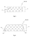
- FIG. 2 an embodiment of a shaped body 210 of an implant 112 is shown in different views.
- the top view shows a top view, the middle view a sectional view from the side without curvature and the bottom view a sectional view from the side with a curvature.
- the diameter D is preferably not more than 10 mm, and the thickness d is preferably about 250 microns.
- the radius of curvature R (lowermost representation) is preferably between 8 mm and 14 mm.
- edge shape 212 shows a substantially rectangular edge, such as may be created by means of a mold
- edge shape 214 shows a tapered shape.
- the edges of the edge shape 214 are perpendicular to a disc plane of the shaped body 210.
- Such an edge profile 214 may arise, for example, by a lithographic manufacturing process, in which for curing the shaped body 210 is irradiation perpendicularly from above.
- FIGS. 3 and 4 Further embodiments of edge shapes of a shaped body 210 are shown. So shows FIG. 3 a partially oblique edge shape.
- the thickness of the molded body 210 decreases from the initial thickness d towards the edge to the thickness d '.
- the edge thickness d ' may be 15 microns to 250 microns. This results, for example, a contact angle, which in FIG. 3 is denoted by ⁇ , from 0 ° to 60 °.
- FIG. 4 two possible edge courses 410, 412 of a shaped body 210 are superimposed, which can be used in further exemplary embodiments.
- This is with the reference numeral 410 designates an edge geometry which (for example by using a corresponding casting mold) has a rounded (eg circular or elliptical profile).
- Reference numeral 412 denotes an edge geometry which has a curved course, for example by using a laser ablation method. This curved course 412 may be provided on one side (solid line 412) or on both sides (in FIG. 4 shown in dashed lines).
- the shape of the hydrogel article 210 can be defined, for example, by a corresponding casting mold.
- the mold is preferably made to account for shrinkage or swelling upon curing of the initial molding formulation.
- the casting mold can be wholly or partly made of a plastic such as polypropylene (PP), polymethylmethacrylate (PMMA), polycarbonate (PC), polyoxymethylene (POM) or polyetheresterketone (PEEK) or glass (UV-translucent).
- PP polypropylene
- PMMA polymethylmethacrylate
- PC polycarbonate
- POM polyoxymethylene
- PEEK polyetheresterketone
- the edge geometry is defined by the closed mold.
- the rim can be photolithographically defined by UV crosslinking or by the surface tension between prepolymer solution and mold material.
- the edge can be defined by cutting.
- a mechanical cutting results in a largely rectangular edge geometry.
- a "rounded" edge can be achieved using a Gaussian intensity profile.
- Alginic acid sodium salt is dissolved in deionized water at 55 ° C with stirring.
- the alginate solution is sprayed by means of a two-component atomizing nozzle (Spraying Systems Co.) into an ultrasonic bath filled with calcium chloride solution, where the alginate drops harden.
- the hardened alginate particles are filtered through a 30 ⁇ m filter cloth and the filtrate is concentrated by settling in a separating funnel. Subsequently, the alginate particles are autoclaved as a 10% solution. Depending on the desired water content of the alginate particles, the concentration of the alginate solution can be varied between 0.2% and 10%.
- Alginattyps molecular weight, ratio guluronic acid to manuronic acid
- the alginate particles are centrifuged off and mixed in the ratio 1: 1 (w / v) with polyallylamine hydrochloride in 10 mM acetate buffer, pH 5.5 and incubated for 5 min. The mixture will centrifuged, the supernatant was removed and the alginate particles were washed twice in the ratio 1: 2 (w / v) with 10 mM acetate buffer, pH 5.5 for 2 min each time and centrifuged off. This procedure is repeated with polystyrenesulfonate in 10 mM acetate buffer, pH 5.5 as the second layer. The process is repeated until the desired number of layers has been applied. The number of layers as well as the concentration of the polyelectrolytes determines the density of the precoat. Typical concentrations are between 0.05% and 1%, typical layer numbers between 1 and 6.
- the (optionally precoated) alginate particles are centrifuged off, washed once with deionized water and again centrifuged off.
- the required amount of dextran is weighed and dissolved in water.
- 1 ml of the dextran solution is added to 1 g of centrifuged alginate particle pellet, mixed by shaking, homogenized in an ultrasonic bath and incubated overnight at 2-8 ° C.
- the alginate beads are then centrifuged off and separated from the supernatant.
- the amount of dextran absorbed is calculated by subtraction of the specific absorptions of supernatant before and after loading. Typical loadings are between 0.01 and 10 mg dextran per g alginate particle.
- ConA is dissolved in a concentration of 5-15 mg / ml in TRIS buffer, pH 7.4. The required amount of ConA is added to the dextran-filled alginate particle pellet, mixed by shaking, homogenized in an ultrasonic bath and incubated overnight at 2-8 ° C. The alginate beads are then centrifuged off and separated from the supernatant. The absorbed amount of ConA is calculated by subtraction of the protein-specific absorptions of supernatant before and after loading.
- the loaded (optionally precoated) alginate beads are mixed in the ratio 1: 1 (w / v) with polystyrene sulfonate in 10 mM acetate buffer, pH 5.5 and incubated for 5 min.
- the mixture is centrifuged, the supernatant is removed and the alginate beads are washed twice in the ratio 1: 2 (w / v) with 10 mM acetate buffer, pH 5.5, for 2 minutes each time and centrifuged off.
- This procedure is repeated alternately with polyallylamine hydrochloride in 10 mM acetate buffer, pH 5.5, and polystyrene sulfonate in 10 mM acetate buffer, pH 5.5, until the desired number of layers are applied.
- the number of layers as well as the concentration of the polyelectrolytes determines the density of the precoat. Typical concentrations are between 0.05% and 1%, typical layer numbers between 10 and 60.
- a 10% reference particle suspension is homogenized in an ultrasonic bath. 990 mg of coated sensor particles are mixed with 8.415 g of a 20 to 40% solution of acrylamidoacetaldehyde-1,3-acetal of polyvinyl alcohol by stirring. 495 ⁇ l of 10% reference particle suspension are pipetted and the mixture is homogenized in an ultrasonic bath. Thereafter, the formulation is rolled for about 3 hours on a roller block.
- the formulation is filled into a syringe and dosed by means of a compressed air-operated dosing unit into a shaped body (female side BK7 glass, male side quartz glass).
- a shaped body female side BK7 glass, male side quartz glass.
- the molding is closed and irradiated under UV light (Hamamatzu Mercury Xenon lamp) for about 5 sec.
- UV light Hamatzu Mercury Xenon lamp
- Implants are already made with 2 and 4 mm diameter and a thickness of about 140 to 250 microns and implanted into the human eye. Implants with radii of curvature of 12 mm, 8.6 mm and planar implants are used. The edges are defined by punching or by positive locking.
Abstract
Description
- Die Erfindung betrifft Hydrogelformkörper, die so aufgebaut sind, dass ein zu bestimmender Analyt in der wässrigen Phase eines Hydrogel-Netzwerks frei diffundieren kann, die chemischen bzw. biochemischen Sensorkomponenten aber im Netzwerk immobilisiert sind. Die äußere Form und die mechanischen Eigenschaften des Hydrogelformkörpers sind für die Implantation und den Implantationsort optimiert. Derartige Hydrogelformkörper können beispielsweise eingesetzt werden, um Analyten, insbesondere bestimmte Metaboliten, in einem Körpergewebe, insbesondere einer Körperflüssigkeit, zu detektieren. Insbesondere kann es sich bei dem Körpergewebe um ein Körpergewebe eines Auges handeln und bei der Körperflüssigkeit um eine Augenflüssigkeit (z.B. Kammerwasser, Tränenflüssigkeit oder interstitielle Flüssigkeit). Auch für andere Gewebearten und/oder Arten von Körperflüssigkeiten ist der vorgeschlagene Hydrogelformkörper jedoch grundsätzlich einsetzbar.
- Die Detektion des mindestens einen zu bestimmenden Analyten kann von einer rein qualitativen Detektion bis hin zu einer quantitativen Detektion reichen. Derartige Detektionsverfahren können beispielsweise zur Bestimmung einer Glukosekonzentration in dem Körpergewebe, beispielsweise in der Augenflüssigkeit, genutzt werden. Aus dieser Analyt- bzw. Glucosekonzentration kann dann anschließend unter Bezugnahme auf bekannte Korrelationen beispielsweise auf eine Konzentration des Analyten, insbesondere der Glucose, in anderen Körperflüssigkeiten, beispielsweise in Blut geschlossen werden. Neben Glucose ist die vorliegende Erfindung, alternativ oder zusätzlich, auch auf andere Arten von Analyten anwendbar.
- Herkömmliche Systeme zur Bestimmung von Analyt- bzw. Metabolitkonzentrationen, insbesondere der Blutglukosekonzentration, basieren in der Regel darauf, dass der Patient oder ein Arzt, beispielsweise mittels eines geeigneten Lanzettensystems, einen Hautbereich perforiert und dadurch eine Blutprobe generiert. Diese Probe wird anschließend mittels geeigneter Messverfahren, beispielsweise optischer und/oder elektrochemischer Messverfahren, auf ihren Analytgehalt analysiert. Neben einem Nachweis in Blut kann auch ein Nachweis in anderen Körperflüssigkeiten, wie beispielsweise in Urin erfolgen.
- Um die mit der häufigen Generierung von Blutproben verbundenen Unannehmlichkeiten der Patienten zu verringern, wurden verschiedene nicht-invasive oder minimal-invasive Technologien zur Messung von Analytkonzentrationen entwickelt. Im Folgenden wird dabei ohne Beschränkung des Schutzumfangs der Erfindung auf die Bestimmung der Blutglukosekonzentrationen eingegangen, wobei naturgemäß auch andere Arten von Analyten bzw. Metaboliten nachweisbar sind.
- Eine Technologie der Blutglukosekonzentrationsbestimmung basiert auf der Messung von Glukose in Körpergewebe und Körperflüssigkeiten, insbesondere in Augenflüssigkeiten, wie beispielsweise Tränenflüssigkeit, Kammerwasser oder interstitieller Flüssigkeit. So ist beispielsweise in
WO 01/13783 - Auch
WO 02/087429 - Die zitierten Druckschriften aus dem Stand der Technik stellen nur einige Ausführungsbeispiele dafür dar, wie Analyten durch geeignete Sensoren in einem Implantat, beispielsweise einem Augenimplantat, erfasst und in ihrer Konzentration bestimmt werden können. Ein zentraler Aspekt stellt jedoch in den meisten Fällen die Ausgestaltung des Implantats, insbesondere des Augenimplantats, selbst dar, welches für die Analytik zahlreichen Anforderungen und Randbedingungen genügen muss. Als geeignetes Matrixmaterial für derartige Implantate haben sich insbesondere Hydrogele erwiesen. Hydrogele sind wasserenthaltende, jedoch zumindest weitgehend wasserunlösliche Polymere, deren Moleküle chemisch, z. B. durch kovalente oder ionische Bindungen, oder physikalisch, z. B. durch Verschlaufen der Polymerketten, zu einem dreidimensionalen Netzwerk verknüpft sind. Hydrogele weisen in der Regel hydrophile Polymerkomponenten auf, welche bewirken, dass die Hydrogele in Wasser unter beträchtlicher Volumenzunahme aufquellen, wobei jedoch ihr stofflicher Zusammenhalt zumindest weitgehend erhalten bleibt. Hydrogele weisen eine hohe Biokompatibilität auf und haben zumeist gewebeähnliche mechanische Eigenschaften.
- Hydrogelformkörper mit bestimmten Zusatzstoffen, die im Hydrogel-Netzwerk eingebettet sind, sind aus dem Stand der Technik bekannt, wobei unter einem Hydrogel-Netzwerk ein wasserenthaltendes Netzwerk verstanden wird, das aus einem Polymer aufgebaut ist, das entweder an sich wasserunlöslich ist oder durch geeignete Maßnahmen wasserunlöslich gemacht wurde. Zu solchen geeigneten Maßnahmen kann sich insbesondere die Erzeugung von kovalenten oder ionischen Bindungen zwischen den Polymerbausteinen des Netzwerks gehören; auch physikalische Maßnahmen wie Verschlaufungen der Polymerbausteine sind bekannt.
- Zu den Hydrogelformkörpern, die im Stand der Technik beschrieben werden, zählen z. B. Implantate für das Auge, die entweder von außen auf die Oberfläche des Auges aufgebracht (z. B. Kontaktlinsen) oder in eine Schicht beziehungsweise Kammer des Auges implantiert (z. B. Intraokularlinsen) werden. Beispiele dafür sind die in den nachfolgend aufgeführten Patentdokumenten beschriebenen Formkörper.
- Das ophthalmische Implantat zur Kontrolle des Grauen Stars aus der
US 5,127,901 wird zwischen die Sclera (Lederhaut) und die Konjunktiva (Bindehaut) eingebracht und weist eine dafür geeignete Form auf. - Die Implantate der
US 5,300,114 oderUS 5,476,511 eröffnen die Möglichkeit, dass unterhalb der Konjunktiva medizinisch aktive Stoffe wirksam sein können. Ethylen-VinylacetatCopolymere werden als besonders geeignetes Polymer für das Implantat angesehen, das auch eine geeignete Diffusionsbarriere für den gezielt freizugebenden Wirkstoff darstellt, der sich z. B. in einer inneren Matrix aus diesem Polymer befindet. Auch die Matrix mit dem Wirkstoff umhüllende Membran ist aus diesem Polymer aufgebaut. Zusätzlich enthalten diese Implantate einen Zusatzstoff, der den Verbrauch des Wirkstoffs anzeigt. Außerdem können diese Implantate auch Beschichtungen oder Abschnitte an bestimmten Stellen des Formkörpers aufweisen, die gerade nicht durchlässig - auch nicht zeitweilig - für den Wirkstoff sind, falls dies an bestimmten Stellen des Auges so erwünscht ist. - Die Implantate der
US 6,416,777 undUS 6,986,900 werden so ins Auge eingebracht, dass der medizinisch aktive Wirkstoff oberhalb der Macula (gelber Fleck der Netzhaut) angeordnet ist und das Implantat sich außerhalb der Sclera befindet. Ihre Geometrien weisen F-, C- oder L-Form auf. Das den Wirkstoff enthaltende Innere kann z. B. Tablettenform haben und das Polymere kann - je nach Anwendungsziel - für den Wirkstoff mehr oder weniger durchlässig sein. Das Polymer soll biokompatibel und nicht biologisch abbaubar sein. Acrylate und Silikone werden als bevorzugt aufgeführt. In einer Variante ist der Wirkstoff in einer Flüssigkeit gelöst, so dass für eine gezielte Abgabe aus dem Implantat gesorgt werden muss. - Die an solche Formkörper mit einem medizinisch aktiven Wirkstoff gestellten Anforderungen sind aber nicht ohne weiteres auf Formkörper übertragbar, in die Analyten eindringen und dort untersucht werden sollen. In letzterem Fall, bei welchem durch den Hydrogel-Formkörper Analyten nachgewiesen werden sollen, sind sogar oftmals diametral entgegen-gesetzte Anforderungen im Vergleich zu Wirkstoff-Implantaten zu stellen, da das bzw. die Sensormaterialien ja gerade nicht oder nur geringfügig im Implantat diffundieren sollen, sondern ortsgebunden im Implantat verbleiben sollen. Andererseits soll es dem nachzuweisenden Analyten ermöglicht werden, nahezu ungehindert und schnell zum Ort des Nachweises im Implantat zu diffundieren, damit die Analytkonzentration zeitnah erfasst werden kann. Dies stellt eine wesentliche Voraussetzung dafür dar, dass ggf. medizinische Gegenmaßnahmen ergriffen werden können, wie beispielsweise eine entsprechende Medikation von Insulin.
- Aufgabe der vorliegenden Erfindung ist es daher, einen Hydrogelformkörper bereitzustellen, welcher den Nachweis eines oder mehrerer Analyten in einer Körperflüssigkeit, beispielsweise einer Augenflüssigkeit, ermöglicht und welcher die Nachteile bekannter Hydrogelformkörper zumindest weitgehend vermeidet. Insbesondere soll ein Hydrogelformkörper bereitgestellt werden, dessen äußere Form und dessen weiterer Aufbau es ermöglichen, dass sich im Hydrogel neben einem zu bestimmenden Analyten (z. B. Glukose), mindestens eine Sensorkomponente und gegebenenfalls noch mindestens eine Referenzkomponente befinden.
- Diese Aufgabe wird durch die Erfindung mit den Merkmalen des unabhängigen Anspruchs gelöst. Vorteilhafte Weiterbildungen der Erfindung sind in den Unteransprüchen gekennzeichnet. Der Wortlaut sämtlicher Ansprüche wird hiermit durch Bezugnahme zum Inhalt dieser Beschreibung gemacht.
- Ein Grundgedanke der vorliegenden Erfindung besteht darin, eine Immobilisierung einer Sensorkomponente in dem Implantat durch eine Verkapselung der Komponenten in Mikro-oder Nanopartikeln vorzunehmen, die in einer Hydrogelmatrix verteilt, insbesondere dispergiert, sind. Besonders bevorzugt ist dabei eine zumindest im Wesentlichen homogene Verteilung.
- Es wird daher ein Implantat zum Nachweis mindestens eines Analyten in einer Körperflüssigkeit, insbesondere einer Augenflüssigkeit, vorgeschlagen, welches eingerichtet ist, um in ein Körpergewebe eines Patienten, insbesondere eine Gewebeschicht und/oder eine Kammer eines Auges des Patienten, implantiert zu werden. Der Begriff eines Patienten umfasst dabei allgemein Lebewesen, insbesondere Menschen, wobei der Begriff nicht notwendigerweise eine Krankheit impliziert. So können auch beispielsweise Messungen an gesunden Menschen oder Tieren vorgenommen werden, um eine Metabolitkonzentration zu messen, um gegebenenfalls rechtzeitig Krankheiten erkennen zu können. Der Begriff Implantat soll jedoch auch den Fall umfassen, dass keine Implantation im eigentlichen Sinne vorgenommen wird, d.h. eine Einbringung in ein Gewebe eines Patienten, sondern soll auch ein einfaches Aufbringen auf ein derartiges Gewebe umfassen, also ein Aufbringen ohne die Notwendigkeit eines chirurgischen Eingriffes, also beispielsweise eine Kontaktlinse und/oder ein Inlay, welches beispielsweise unter einem Augenlid eines Patienten platziert werden kann.
- Das Implantat weist eine Hydrogelmatrix mit mindestens einem Hydrogel auf, wobei das Implantat weiterhin in der Hydrogelmatrix dispergierte Sensorpartikel aufweist, wobei die Sensorpartikel mindestens eine Sensormatrix mit einem Sensormatrixmaterial (122) und mindestens ein Sensormaterial aufweisen.
- Die Sensorpartikel sind vorzugsweise als Mikro- oder Nanopartikel ausgestaltet, vorzugsweise mit einem Partikeldurchmesser im Bereich weniger Mikrometer (z.B. <100 Mikrometer, vorzugsweise <20 Mikrometer) bis hin zu einigen 100 Nanometern.
- Die Mikro- oder Nanopartikel sind vorzugsweise permeabel gegenüber dem Analyten entweder aufgrund ihrer Struktur oder aufgrund einer semipermeablen Hülle. Das Innere der Partikel ist so gestaltet, dass die Sensorkomponenten eine optimale Aktivität aufweisen.
- Das Sensormaterial ist derart ausgestaltet, dass dieses sensitiv auf den nachzuweisenden Analyten reagiert. Vorzugsweise ist diese Sensoreigenschaft spezifisch für den nachzuweisenden Analyten. Dabei können, wie aus dem oben beschriebenen Stand der Technik bekannt, verschiedene Nachweisprinzipien eingesetzt werden. Beispielsweise kann der Analyt mit dem Sensormaterial chemisch reagieren (z.B. eine kovalente Bindung, eine Komplexbindung oder eine ähnliche Verbindung eingehen), wobei diese Bindung beispielsweise durch Änderung von Fluoreszenzeigenschaften des Analyten und/oder des Sensormaterials und/oder der Sensormaterial-Analyt-Verbindung nachgewiesen werden kann. Auch lockerere Bindungen sind möglich, beispielsweise physikalische Bindungen und/oder Annäherungen von Sensormaterial und Analyt, welche beispielsweise wiederum spektroskopisch nachgewiesen werden können. In jedem Fall ist das Sensormaterial jedoch derart ausgestaltet, dass sich mindestens eine nachweisbare physikalische und/oder chemische Eigenschaft des Implantats ändert, wenn sich die Analytkonzentration in der Körperflüssigkeit, insbesondere der Augenflüssigkeit, ändert bzw. wenn Analyt in der Körperflüssigkeit vorhanden ist.
- Ein wesentlicher Aspekt und Vorteil der Erfindung ist die Tatsache, dass die Eigenschaften von Hydrogelmatrix und Sensorpartikeln getrennt optimiert werden können. So benötigt man Implantate mit einer guten mechanischen Festigkeit, die bei Hydrogelen im Wesentlichen durch höhere Netzwerkdichte und relativ geringen Wassergehalt erzielt werden kann.
- Werden jetzt aber für das Sensormaterial beispielsweise relativ große Biomoleküle wie Con A (104 kD), Glukoseoxidase (63 kD), Glukosedehydrogenase, Hexokinase oder Glucose Galactose binding protein (GGBP) verwendet, deren Funktionalität vom Vorliegen der nativen Konfiguration sowie von der Beweglichkeit der Biomoleküle abhängt, so wirken sich allerdings geringe Wassergehalte und dichte Netzwerke ungünstig auf die Aktivität und Beweglichkeit der Proteine aus. In den Mikropartikeln können die Umgebungsbedingungen für solche Proteine und/oder andere Sensorkomponenten unabhängig von den Anforderungen an das Implantat optimiert werden. Weiterhin kann das Sensormaterial auch ein Protein und/oder ein funktionell äquivalentes Fragment umfassen, Mutanten von Hexokinase und/oder GGBP und/oder Borsäureesterderivate.
- So können beispielsweise Hydrogele auch für die Mikropartikel bzw. Sensorpartikel verwendet werden, deren Wassergehalt über 90% beträgt. Da in solchen Fällen die Proteine wegen der geringen Netzwerkdichte teilweise aus den Partikeln heraus diffundieren könnten, werden die Sensorpartikel vorzugsweise mit einer semipermeablen Schicht beschichtet.
- Dies können "klassische" LBL ("layer-by-layer")-Schichten sein, es können aber auch vernetzte Proteine, Polysaccharide oder andere Polymere eingesetzt werden, die eine zweite, dichtere Hydrogelschicht um das Innere des Partikels bilden. Der Begriff LBL bezieht sich dabei auch auf die nacheinander folgende Abscheidung von entgegengesetzt geladenen Polyelektrolyten. Man kann zum Beispiel einen Sensorpartikel zunächst mit einem negativ oder positiv geladenen Polyelektrolyten beschichten und anschließend mit einem entsprechend entgegengesetzt geladenen Polyelektrolyten. Diesen Vorgang kann man wiederholen, bis die gewünschte Schichtdicke und Permeabilität erzielt wird. Es gibt auch Varianten, bei denen teilweise ungeladene Polymerschichten zwischen zwei entgegengesetzt geladenen Schichten eingebracht werden. Alternativ kann man die "LBL" Schicht auch nicht schrittweise sondern durch einen Schritt aufbauen, indem in der Beschichtungslösung Komplexe aus den beiden entgegengesetzt geladenen Polyelektrolyten gebildet werden, die sich unter bestimmten Bedingungen auf der Oberfläche der Partikel abscheiden. Sind die Sensorkomponenten sehr groß oder ist die die Mikropartikel umhüllende Hydrogelmatrix besonders dicht, so können auch Mikropartikel ohne Membran verwendet werden.
- Geeignete Lösungen für solche speziellen Sensorpartikel, insbesondere in dem Aufbau der LBL-Schichten, werden beispielsweise in den folgenden Patentdokumenten offenbart:
WO 2005/089727 ,WO 2004/014540 ,WO 02/017888 WO 00/077281 WO 00/003797 EP-A 1 116 516 ,WO 99/047252 WO 99/047253 US 6,451,871 ,US 6,896,926 ,US 7,022,379 undUS 6,926,965 . - Geeignete Materialien für Sensorpartikel sind z.B. ionisch vernetzte Alginate und Mischungen von Alginaten und Polysacchariden oder Polysaccharidderivaten wie Carboxymethylcellulose oder aber auch synthetische Polymere bzw. Copolymere wie Polyhydroxyethylmethacrylat (P-HEMA), Polyacrylamide und Copolymere aus Acrylsäure und/oder Acrylsäure- und Methacrylsäurederivate wie Dimethylacrylamid, Hydroxyethyacrylat, Methacrylsäure. Grundsätzlich sind alle Polymere denkbar, die wasserlöslich und vernetzt oder vernetzbar sind. Es ist auch möglich, für die Sensorpartikel das gleiche Polymer wie für die Hydrogelmatrix zu benutzen, wobei sich im Allgemeinen jedoch die Polymere in ihrem Vernetzungsgrad unterscheiden sollten. Ein Beispiel hierfür sind Polyvinylalkohole mit unterschiedlichen Mengen funktioneller, vernetzbarer Gruppen.
- Geeignete Hydrogele für die Sensorpartikel und/oder auch für die Hydrogelmatrix werden z. B. in den nachfolgenden Patentdokumenten offenbart:
EP-B 0 641 806 ,EP-B 0 790 258 ,EP-B 0 807 265 undEP 0 637 490 . - Neben Sensorpartikeln mit Mikro- oder Nanopartikeln, die die Sensormaterialien bzw. Sensorkomponenten enthalten, weist das Implantat vorzugsweise weiterhin mindestens eine zumindest weitgehend Analyt-invariante Referenzkomponente auf. Die Referenzkomponente kann insbesondere mindestens eine lumineszierende Komponente, insbesondere eine Fluoreszenzkomponente, aufweisen. Die Lumineszenzeigenschaften der luminszierenden Komponente sollen zumindest weitgehend Analyt-invariant sein.
- Die Referenzkomponente kann grundsätzlich auf verschiedene Weisen in das Implantat eingebracht werden. Beispielsweise kann die Referenzkomponente auf beliebige Weise in die Hydrogel- oder Sensormatrix eingebracht sein, beispielsweise in der Matrix dispergiert, gelöst, emulgiert oder suspensiert sein. Auch eine chemische Bindung, beispielsweise eine kovalente Bindung, eine ionische Bindung oder eine Komplexbindung, an eine oder mehrere Komponenten des Implantats, beispielsweise an die Hydrogelmatrix, ist möglich.
- In einer besonders bevorzugten Ausführungsform wird mindestens eine Referenzkomponente mittels Referenzpartikeln in das Implantat eingebracht. So können Referenzpartikel in die Hydrogelmatrix eingebettet werden, die eine oder mehrere Referenzkomponenten enthalten. Weiterhin kann ein Referenzmatrixmaterial enthalten sein. Wiederum können diese Referenzpartikel vorzugsweise Mikro- oder Nanopartikel aufweisen, vorzugsweise mit einem Partikeldurchmesser im Bereich weniger Mikrometer (z.B. <100 Mikrometer, vorzugsweise <10 Mikrometer) bis hin zu einigen 100 Nanometern.
- Grundsätzlich kann für das Referenzmatrixmaterial das oben bezüglich der Hydrogelmatrix Gesagte entsprechend gelten. Insbesondere können für das Referenzmatrixmaterial ebenfalls eine oder mehrere der oben beschrieben Materialien eingesetzt werden. Auch die Verwendung einer Hülle um die Referenzpartikel ist wiederum möglich, wobei bezüglich der Materialien und weiteren Eigenschaften ebenfalls wiederum auf das oben zur Hülle der Sensorpartikel Gesagte analog verwiesen werden kann. Die Sensor- und/oder Referenzpartikel sollten dabei relativ klein bezogen auf die Dicke des Hydrogelformkörpers sein, damit eine homogene Verteilung im Hydrogel bzw. Referenzmatrixmaterial möglich ist. Der Durchmesser sollte vorzugsweise nicht größer als ca. 10 % der Dicke des Hydrogels bzw. des Hydrogelformkörpers sein.
- Die Referenzkomponenten können z. B. Fluoreszenzfarbstoffe oder hochmolekulare Derivate von Fluoreszenzfarbstoffen sein oder umfassen, die entweder auf der Oberfläche des Hydrogels, der Sensorpartikel und/oder der Referenzpartikel oder in der Matrix (Matrixmaterial) der Referenz- oder Sensorpartikel chemisch oder physikalisch gebunden sind.
- Vorzugsweise sind die Referenzkomponenten zumindest weitgehend Analyt-invariant, d.h. ändern ihre nachweisbaren physikalischen und/oder chemischen Eigenschaften (z.B. wiederum Fluoreszenz- und/oder Lumineszenzeigenschaften) im Wesentlichen auch bei Anwesenheit des nachzuweisenden Analyten nicht oder nur unwesentlich (z.B. um nicht mehr als 5%, vorzugsweise weniger).
- Zur oberflächlichen Anbindung der Farbstoffe können kovalente Bindungen dienen oder aber auch starke Komplexbindungen wie Biotin-Avidin. In diesen Fällen werden funktionelle Gruppen an der Oberfläche der Partikel mit funktionellen Gruppen am Farbstoffinolekül umgesetzt. Entsprechende Synthesevorschriften zur Kopplung von z.B. Amino-Gruppen, Thiol-Gruppen und Carboxy-Gruppen sind literaturbekannt. Auch können die Farbstoffe in LBL-Schichten oder anderen Schichten, die auf inerten Partikeln aufgebracht werden, eingebettet sein. In diesen Fällen kann der Farbstoff entweder aufgrund seiner z.B. Ladungseigenschaften zusammen mit den Polyelektrolyten abgeschieden werden, oder der Farbstoff ist direkt an einen der Polyelektrolyten kovalent gebunden.
- Zur Bindung in den Partikeln können die Referenzkomponenten (im Folgenden ohne Beschränkung der allgemeinen Ausgestaltungsmöglichkeiten auch einfach "Farbstoffe" oder "Farbstoffinolekül" oder "Farbstoffgruppe" genannt) zum Beispiel direkt mit Monomeren polymerisiert werden und als Partikel gestaltet werden. In diesem Fall ist das durch die Polymerisation der Monomere entstehende Netzwerk vorzugsweise so engmaschig, dass das Farbstoffmolekül nicht mehr hinaus diffundieren kann. Eine solche physikalische Immobilisierung kann auch durch Quellung der Partikel in geeigneten Lösungsmitteln und Inkubation der gequollenen Partikel in einer Farbstofflösung erreicht werden. Dabei macht man sich die Tatsache zunutze, dass das Netzwerk in guten Lösungsmitteln seine Porengröße vergrößert (z.B. Polystyrol in Toluol) und nach Eindiffundieren der Farbstoffinoleküle im Anwendungslösungsmittel (Wasser oder physiologischer Lösung) die Porengröße wieder verringert. Dies ist besonders bei empfindlichen Farbstoffen von Vorteil, da so für den Farbstoff die Bedingungen der Polymerisation umgangen werden.
- Eine andere Variante besteht darin, dass das Farbstoffinolekül selbst polymerisierbare funktionelle Gruppen enthält und zusammen mit dem Monomer copolymerisiert wird. Die Referenzpartikel zeichnen sich dadurch aus, dass sich ihr Messparameter z.B. Fluoreszenz nicht mit der Konzentration des Analyten ändert.
- Das Implantat kann insbesondere einen Hydrogelformkörper aufweisen. Der Hydrogelformkörper selbst wird dann vorzugsweise aus einem wasserlöslichen vernetzbaren Präpolymer und den Sensor- und Referenzpartikeln hergestellt. Dabei werden die Partikel in einer wässrigen Lösung der Präpolymeren homogen dispergiert und die wässrige Dispersion anschließend vernetzt (radikalisch z.B. photochemisch oder thermisch oder in 2+2 Cycloaddition).
- Der Formkörper weist bevorzugt einen maximalen Durchmesser von 10 mm und ein Oberflächen zu Volumen-Verhältnis von mindestens 8 auf. Diese Weiterbildung der Erfindung bewirkt, dass die Ansprechgeschwindigkeit des Implantats auf Änderungen der Analytkonzentration in der Augenflüssigkeit typischerweise einen Wert von wenigen Minuten, vorzugsweise von nicht mehr als 3-4 Minuten, nicht übersteigt. Der Formkörper muss nicht zwangsläufig eine runde Scheibe sein. Vielmehr sind beliebige Formen möglich, solange der die Form umschreibende Kreis nicht größer 10 mm ist.
- Der Rand des Formkörpers kann im Wesentlichen rechtwinklig sein, wobei jedoch unter "im Wesentlichen" auch Abweichungen von bis zu 60°, vorzugsweise jedoch von nicht mehr als 20° und besonders von nicht mehr als 5° toleriert werden können. Die Dicke des Formkörpers nimmt bevorzugt zum Rand hin ab. Der Rand hat einen bevorzugten Winkel von 0° bis 60°. Die Kanten können bevorzugt abgerundet sein. Der Formkörper kann planar oder gewölbt sein. Die Wölbung hat bevorzugt einen Krümmungsradius von 14 mm bis 8 mm. Der Krümmungsradius der Wölbung soll insbesondere nicht kleiner 8 mm sein.
- Zusammengefasst kann der Hydrogelformkörper, welchen das Implantat aufweisen kann, insbesondere über die folgenden Eigenschaften verfügen:
- Der Hydrogelformkörper kann eine im Wesentlichen flache, runde Gestalt aufweisen, wobei der Durchmesser des Hydrogelformkörpers nicht größer sein kann als 10 mm.
- Der Hydrogelformkörper kann ein Oberflächen-zu-Volumen-Verhältnis von mindestens 5, vorzugsweise von mindestens 8 aufweisen.
- Der Hydrogelformkörper kann einen im Wesentlichen rechtwinkligen Rand aufweisen.
- Der Hydrogelformkörper kann eine Wölbung mit einem Krümmungsradius zwischen 5 mm und 20 mm, besonders bevorzugt zwischen 8 mm und 14 mm aufweisen.
- Der Hydrogelformkörper kann eine Dicke von nicht mehr als 250 Mikrometern aufweisen.
- Der Hydrogelformkörper kann im Randbereich eine Dicke von nicht mehr als 250 Mikrometern, vorzugsweise eine Dicke zwischen 15 Mikrometern und 250 Mikrometern aufweisen.
- Der Hydrogelformkörper kann einen abgerundeten Rand aufweisen, insbesondere einen abgerundeten Rand mit einem Gaußprofil.
- Der Hydrogelformkörper kann zumindest teilweise unter Verwendung eines Laserablationsverfahrens und/oder eines lithographischen Verfahrens und/oder eines Gussverfahrens hergestellt sein.
- Weitere Einzelheiten und Merkmale der Erfindung ergeben sich aus der nachfolgenden Beschreibung von bevorzugten Ausführungsbeispielen in Verbindung mit den Unteransprüchen. Hierbei können die jeweiligen Merkmale für sich alleine oder zu mehreren in Kombination miteinander verwirklicht sein. Die Erfindung ist nicht auf die Ausführungsbeispiele beschränkt.
- Die Ausführungsbeispiele sind in den Figuren schematisch dargestellt. Gleiche Bezugsziffern in den einzelnen Figuren bezeichnen dabei gleiche oder funktionsgleiche bzw. hinsichtlich ihrer Funktionen einander entsprechende Elemente.
- Im Einzelnen zeigt:
- Figur 1A
- eine Hydrogelmatrix eines Implantats mit Sensorpartikeln mit Membran;
- Figur 1B
- eine Hydrogelmatrix eines Implantats mit Sensorpartikeln ohne Membran;
- Figur 2
- einen Formkörper eines Implantats in verschiedenen Ansichten;
- Figur 3
- eine Schnittdarstellung eines ersten Ausführungsbeispiels eines Formkörpers eines Implantats in einer Seitenansicht; und
- Figur 4
- eine Schnittdarstellung eines zweiten Ausführungsbeispiels eines Formkörpers eines Implantats in einer Seitenansicht.
- In den
Figuren 1A und 1B ist jeweils eine Hydrogelmatrix 110 eines Implantats 112 (das Implantat ist nur symbolisch dargestellt) dargestellt. Im Folgenden wird speziell die Anwendung der Erfindung auf ein Augenimplantat erläutert, wobei jedoch, wie oben ausgeführt, die Erfindung grundsätzlich auch auf Implantate 112 für andere Arten von Körpergewebe einsetzbar ist. Die Hydrogelmatrix 110 des Implantats 112 weist jeweils als Grundkomponente ein Hydrogel 114 auf. Der Wassergehalt, die Netzwerkdichte und die Form der Hydrogelmatrix 110 können jeweils optimiert sein für die spezielle Implantationsanwendung. - In beiden Fällen sind in der Hydrogelmatrix 110 Sensorpartikel 116 verteilt. Die Ausführungsbeispiele in den
Figuren 1A und 1B unterscheiden sich dadurch, dass inFigur 1A die Sensorpartikel 116 eine Membran 118 aufweisen, in dem Ausführungsbeispiel inFigur 1B hingegen nicht. Es sind jedoch auch Ausfiihrungsformen denkbar, in denen sowohl Sensorpartikel 116 mit Membran 118 als auch solche ohne Membran nebeneinander vorliegen. - Die Sensorpartikel 116 weisen jeweils eine Sensormatrix 120 mit einem Sensormatrixmaterial 122 und einem in dem Sensormatrixmaterial aufgenommenen Sensormaterial 124 auf. Das Sensormaterial 124 ist sensitiv für einen Analyten 126, welcher in den
Figuren 1A und 1B symbolisch mit der Bezugsziffer 126 bezeichnet ist und welcher durch die Hydrogelmatrix 110 und vorzugsweise auch durch die Sensormatrix 120 diffundieren kann. - Weiterhin sind in der Hydrogelmatrix 110 in den dargestellten Ausführungsbeispielen Referenzpartikel 128 verteilt. Diese weisen ein Referenzmatrixmaterial 130 und eine Referenzkomponente 132 auf, wobei die Referenzkomponente 132 in diesem Ausführungsbeispiel an der Oberfläche und/oder im Inneren des Referenzmatrixmaterials 130 physikalisch und/oder chemisch gebunden ist. Beispielsweise kann ein einpolymerisierter Fluoreszenzfarbstoff und/oder ein auf der Oberfläche des Referenzmatrixmaterials 130 und/oder des Referenzpartikels 128 angebrachter Fluoreszenzfarbstoff als Referenzkomponente 132 verwendet werden.
- In
Figur 2 ist ein Ausführungsbeispiel eines Formkörpers 210 eines Implantats 112 in verschiedenen Ansichten dargestellt. Die obere Ansicht zeigt eine Draufsicht, die mittlere Ansicht eine Schnittdarstellung von der Seite ohne Krümmung und die untere Ansicht eine Schnittdarstellung von der Seite mit einer Krümmung. Der Durchmesser D beträgt vorzugsweise nicht mehr als 10 mm, und die Dicke d vorzugsweise ca. 250 Mikrometer. Der Krümmungsradius R (unterste Darstellung) beträgt vorzugsweise zwischen 8 mm und 14 mm. - Weiterhin sind in der untersten Darstellung der Formkörpers 210 zwei mögliche Randformen überlagert dargestellt. Während die Randform 212 einen im Wesentlichen rechteckigen Rand zeigt, wie er beispielsweise mittels einer Gussform erzeugt werden kann, zeigt die Randform 214 eine spitz zulaufende Form. Hierbei sind vorzugsweise die Ränder der Randform 214 senkrecht zu einer Scheibenebene des Formkörpers 210. Ein derartiger Randverlauf 214 kann beispielsweise durch ein Lithographisches Herstellungsverfahren entstehen, bei welchem zur Aushärtung des Formkörpers 210 eine Bestrahlung senkrecht von oben erfolgt.
- In den
Figuren 3 und 4 sind weitere Ausführungsbeispiele von Randformen eines Formkörpers 210 dargestellt. So zeigtFigur 3 eine teilweise schräg verlaufende Randform. Dabei nimmt die Dicke des Formkörpers 210 von der Ausgangsdicke d zum Rand hin auf die Dicke d' ab. Während die Dicke d beispielsweise 250 Mikrometer betragen kann, kann die Randdicke d' beispielsweise 15 Mikrometer bis hin zu 250 Mikrometer betragen. Damit ergibt sich beispielsweise ein Randwinkel, welcher inFigur 3 mit α bezeichnet ist, von 0° bis hin zu 60°. - In
Figur 4 sind wiederum zwei mögliche Randverläufe 410, 412 eines Formkörpers 210 überlagert, welche in weiteren Ausführungsbeispielen eingesetzt werden können. Hierbei ist mit der Bezugsziffer 410 eine Randgeometrie bezeichnet, welche (beispielsweise durch Verwendung einer entsprechenden Gussform) einen abgerundeten (z.B. kreisbogenförmigen oder elliptischen Verlauf) aufweist. Mit der Bezugsziffer 412 ist eine Randgeometrie bezeichnet, welche einen gekrümmten Verlauf aufweist, beispielsweise durch Verwendung eines Laserablationsverfahrens. Dieser gekrümmte Verlauf 412 kann einseitig vorgesehen sein (durchgezogene Linie 412) oder auch beidseitig (inFigur 4 gestrichelt dargestellt). - Die Form des Hydrogelformkörpers 210 kann beispielsweise durch eine entsprechende Gussform definiert werden. Die Gussform ist vorzugsweise so gefertigt, dass ein Schrumpfen oder Quellen bei der Aushärtung der Ausgangsformulierung für die Formgebung berücksichtigt wird. Die Gussform kann ganz oder teilweise aus einem Kunststoff wie Polypropylen (PP), Polymethylmethacrylat (PMMA), Polycarbonat (PC), Polyoxymethylen (POM) oder Polyetheresterketon (PEEK) oder aus Glas (UV-lichtdurchlässig) bestehen. Im Falle von geschlossenen Formen wird die Randgeometrie durch die geschlossene Gussform definiert. Im Falle von offenen Formen (Glasformen) kann der Rand photolithographisch durch UV-Vernetzung definiert werden oder durch die Oberflächenspannung zwischen Präpolymerlösung und Formmaterial.
- Auch kann im Falle von offenen Formen oder größeren Formstücken der Rand durch Ausschneiden definiert werden. Bei einem mechanischen Ausschneiden ergibt sich eine weitgehend rechteckige Randgeometrie. Bei einem Ausschneiden mittels Laser kann bei Verwendung eines Gauß-Intensitätsprofils eine "abgerundete" Kante erzielt werden.
- Nachfolgend wird die Herstellung eines Hydrogelformkörpers beispielhaft dargestellt.
- Alginsäure-Natriumsalz wird in deionisiertem Wasser bei 55 °C unter Rühren gelöst. Die Alginatlösung wird mittels einer Zweistoffzerstäuberdüse (Firma Spraying Systems Co.) in ein mit Calciumchloridlösung befülltes Ultraschallbad versprüht, wo die Alginattropfen aushärten.
- Die ausgehärteten Alginatpartikel werden über ein 30 µm Filtergewebe filtriert und das Filtrat durch Absitzen im Scheidetrichter aufkonzentriert. Anschließend werden die Alginatpartikel als 10%ige Lösung autoklaviert. Je nach gewünschtem Wassergehalt der Alginatpartikel kann die Konzentration der Alginatlösung zwischen 0,2% und 10% variiert werden. Durch entsprechende Wahl des Alginattyps (Molekulargewicht, Verhältnis Guluronsäure zu Manuronsäure) ist ein weiteres Feintuning der Netzwerkdichte möglich.
- Die Alginatpartikel werden abzentrifugiert und im Verhältnis 1:1 (w/v) mit Polyallylamin-Hydrochlorid in 10 mM Acetat-Puffer, pH 5,5 gemischt und 5 min inkubiert. Die Mischung wird zentrifugiert, der Überstand abgenommen und die Alginatpartikel zweimal im Verhältnis 1:2 (w/v) mit 10 mM Acetat-Puffer, pH 5,5 jeweils 2 min gewaschen und abzentrifugiert. Dieser Vorgang wird mit Polystyrolsulfonat in 10 mM Acetat-Puffer, pH 5,5 als zweite Schicht wiederholt. Der Vorgang wird so lange wiederholt, bis die gewünschte Anzahl Schichten aufgebracht wurde. Die Anzahl an Schichten sowie die Konzentration der Polyelektrolyte bestimmt die Dichte der Vorbeschichtung. Typische Konzentrationen sind zwischen 0,05% und 1%, typische Schichtzahlen zwischen 1 und 6.
- Die (optional vorbeschichteten) Alginatpartikel werden abzentrifugiert, einmal mit deionisiertem Wasser gewaschen und wieder abzentrifugiert.
- Die benötigte Menge Dextran wird abgewogen und in Wasser gelöst.
- Auf 1 g abzentrifugiertes Alginatpartikel-Pellet wird 1 ml der Dextranlösung gegeben, durch Schütteln gemischt, im Ultraschallbad homogenisiert und über Nacht bei 2-8 °C inkubiert. Anschließend werden die Alginatkugeln abzentrifugiert und vom Überstand getrennt. Die aufgenommene Menge Dextran wird durch Differenzbildung der spezifischen Absorptionen von Überstand vor und nach Beladung errechnet. Typische Beladungen sind zwischen 0,01 und 10 mg Dextran pro g Alginatpartikel.
- ConA wird in einer Konzentration von 5-15 mg/ml in TRIS-Puffer, pH 7,4 gelöst. Die benötigte Menge ConA wird auf das Dextran-befüllte Alginatpartikel-Pellet gegeben, durch Schütteln gemischt, im Ultraschallbad homogenisiert und über Nacht bei 2-8 °C inkubiert. Anschließend werden die Alginatkugeln abzentrifugiert und vom Überstand getrennt. Die aufgenommene Menge ConA wird durch Differenzbildung der proteinspezifischen Absorptionen von Überstand vor und nach Beladung errechnet.
- Die beladenen (optional vorbeschichteten) Alginatkugeln werden im Verhältnis 1:1 (w/v) mit Polystyrolsulfonat in 10 mM Acetat-Puffer, pH 5,5 gemischt und 5 min inkubiert. Die Mischung wird zentrifugiert, der Überstand abgenommen und die Alginatkugeln zweimal im Verhältnis 1:2 (w/v) mit 10 mM Acetat-Puffer, pH 5,5 jeweils 2 min gewaschen und abzentrifugiert. Dieser Vorgang wird abwechselnd mit Polyallylamin-Hydrochlorid in 10 mM Acetat-Puffer, pH 5,5 und Polystyrolsulfonat in 10 mM Acetat-Puffer, pH 5,5 wiederholt, bis die gewünschte Anzahl Schichten aufgebracht sind. Die Anzahl an Schichten sowie die Konzentration der Polyelektrolyte bestimmt die Dichte der Vorbeschichtung. Typische Konzentrationen sind zwischen 0,05% und 1%, typische Schichtzahlen zwischen 10 und 60.
- Eine 10%ige Referenzpartikel-Suspension wird im Ultraschallbad homogenisiert. 990 mg beschichtete Sensorpartikel werden mit 8,415 g einer 20 bis 40%igen Lösung von Acrylamidoacetaldehydo-1,3-acetal von Polyvinylalkohol durch Rühren gemischt. 495 µl 10%ige Referenzpartikel-Suspension werden zupipettiert und die Mischung im Ultraschallbad homogenisiert. Danach wird die Formulierung ca. 3 Stunden auf einem Rollenblock gerollt.
- Die Formulierung wird in eine Spritze gefüllt und mittels einer Druckluft-betriebenen Dosiereinheit in einen Formkörper (weibliche Seite BK7 Glas, männliche Seite Quarzglas) dosiert. Der Formkörper wird geschlossen und unter UV-Licht (Hamamatzu Mercury-Xenon Lampe) für ca. 5 sec bestrahlt. Das vernetzte Implantat wird aus dem Formkörper entnommen, an Luft getrocknet und verpackt.
- Es werden bereits Implantate mit 2 und 4 mm Durchmesser und einer Dicke von ca. 140 bis 250 µm hergestellt und ins menschliche Auge implantiert. Es kommen Implantate mit Krümmungsradien von 12 mm, 8,6 mm und planare Implantate zum Einsatz. Die Ränder werden durch Ausstanzen oder durch Formschluss definiert.
- Es werden auch Ränder mit Phasen an der Ober- und Unterseite eingesetzt. Das Ausschneiden mittels Excimer Laser wird ebenfalls durchgeführt.
-
- 110
- Hydrogelmatrix
- 112
- Implantat
- 114
- Hydrogel
- 116
- Sensorpartikel
- 118
- Membran
- 120
- Sensormatrix
- 122
- Sensormatrixmaterial
- 124
- Sensormaterial
- 126
- Analyt
- 128
- Referenzpartikel
- 130
- Referenzmatrixmaterial
- 132
- Referenzko mponente
- 210
- Formkörper
- 212
- rechtwinklige Randform
- 214
- spitz zulaufende Randform
- 410
- runder Randverlauf
- 412
- gekrümmter Randverlauf
Claims (15)
- Implantat (110) zum Nachweis mindestens eines Analyten (126) in einer Körperflüssigkeit, insbesondere einer Augenflüssigkeit, wobei das Implantat (110) eingerichtet ist, um in ein Körpergewebe eines Patienten, insbesondere eine Gewebeschicht und/oder eine Kammer eines Auges des Patienten, implantiert zu werden, wobei das Implantat (110) eine Hydrogelmatrix (110) mit mindestens einem Hydrogel (114) aufweist, wobei das Implantat (110) weiterhin in der Hydrogelmatrix (110) homogen dispergierte Sensorpartikel (116) aufweist, wobei die Sensorpartikel (116) mindestens eine Sensormatrix (120) mit einem Sensormatrixmaterial (122) und mindestens ein Sensormaterial (124) aufweisen, wobei das Implantat (110) weiterhin mindestens eine zumindest weitgehend Analyt-invariante Referenzkomponente (132) aufweist, wobei die Referenzkomponente (132) homogen in der Hydrogelmatrix (110) dispergiert ist.
- Implantat (110) nach dem vorhergehenden Anspruch, wobei das Sensormaterial (124) mindestens eines der folgenden Materialien aufweist: Concanavalin A; Glukoseoxidase; Glukosedehydrogenase; Hexokinase; Glucose Galactose-bindendes Protein; ein Protein und/oder ein funktionell einem Protein äquivalentes Fragment; einen Mutanten von Hexokinase; einen Mutanten von Glucose Galactose-bindendem Protein; ein Borsäureesterderivat.
- Implantat (110) nach einem der beiden vorhergehenden Ansprüche, wobei die Sensorpartikel (116) eine für den Analyten (126) zumindest teilweise permeable Hülle (118), insbesondere eine Membran, aufweisen.
- Implantat (110) nach dem vorhergehenden Anspruch, wobei die Hülle (118) diffusionshemmende Eigenschaften für das mindestens eine Sensormaterial (124) aufweisen, insbesondere für das mindestens eine Sensormaterial (124) zumindest weitgehend undurchlässig ist.
- Implantat (110) nach einem der beiden vorhergehenden Ansprüche, wobei die Hülle (118) mindestens eine der folgenden Materialien aufweist: ein vernetztes Protein; ein Polysaccharid; ein vernetztes Polysaccharid; ein Polymer, insbesondere ein Hydrogel mit einer die Dichte des Hydrogels der Hydrogelmatrix (110) übersteigenden Dichte; eine layer-by-layer-Schicht.
- Implantat (110) nach einem der vorhergehenden Ansprüche, wobei das Sensormaterial (124) mindestens eines der folgenden Materialien aufweist:- ein Molekül und/oder eine Gruppe, welche bei Anwesenheit eines Analyten (126) mindestens eine chemische oder physikalische Eigenschaft ändert, insbesondere eine Lumineszenzeigenschaft, insbesondere eine Fluoreszenzeigenschaft;- ein Molekül und/oder eine Gruppe, wobei der Analyt (126) bei Annäherung und/oder Reaktion mit dem Molekül und/oder der Gruppe mindestens eine chemische oder physikalische Eigenschaft ändert, insbesondere eine Lumineszenzeigenschaft, insbesondere eine Fluoreszenzeigenschaft;- ein Molekül und/oder eine Gruppe, wobei der Analyt (126) mit dem Molekül und/oder der Gruppe eine chemische oder physikalische Bindung eingeht, welche durch Änderung mindestens einer chemischen oder physikalischen Eigenschaft nachweisbar ist, insbesondere durch Änderung einer Lumineszenzeigenschaft, insbesondere durch Änderung einer Fluoreszenzeigenschaft.
- Implantat (110) nach einem der vorhergehenden Ansprüche, wobei das mindestens eine Sensormatrixmaterial (122) und die Hydrogelmatrix (110) derart ausgestaltet sind, dass das mindestens eine Sensormaterial (124) in dem Sensormatrixmaterial (122) einen höheren Diffusionskoeffizienten aufweist als in der Hydrogelmatrix (HO), insbesondere als in dem mindestens einen Hydrogel (114) der Hydrogelmatrix (110), wobei das Sensormatrixmaterial (122) vorzugsweise eine geringere Dichte aufweist als die Hydrogelmatrix (110), insbesondere als das Hydrogel (114) der Hydrogelmatrix (110).
- Implantat (110) nach einem der vorhergehenden Ansprüche, wobei das Sensormatrixmaterial (122) ein Hydrogel mit einem Wassergehalt aufweist, welcher den Wassergehalt des Hydrogels (114) der Hydrogelmatrix (110) übersteigt, wobei das Hydrogel des Sensormatrixmaterials (122) insbesondere einen Wassergehalt von mindestens 70 Gewichtsprozent, vorzugsweise von mindestens 85 Gewichtsprozent, aufweist.
- Implantat (110) nach einem der vorhergehenden Ansprüche, wobei das Sensormatrixmaterial (122) mindestens eines der folgenden Materialien aufweist: ein Alginat, insbesondere ein ionisch vernetztes Alginat; ein Polysaccharid; ein Polysaccharidderivat, insbesondere Carboxymethylcellulose; ein synthetisches kovalent oder über Wasserstoffbrückenbindung vernetztes oder ionisch vernetztes Polymer oder Copolymer, insbesondere Polyvinylalkohol und/oder Polyhydroxyethylmethacrylat; ein Polyacrylamid; ein eine Acrylsäure-Einheit enthaltendes Copolymer; ein Acrylsäurederivat oder ein Methacrylsäurederivat, insbesondere Dimethylacrylamid, Hydroxyethyacrylat oder Methacrylsäure.
- Implantat (110) nach einem der vorhergehenden Ansprüche, wobei die Hydrogelmatrix (110) und das Sensormatrixmaterial (122) ein chemisch identisches Hydrogel (114) mit jeweils unterschiedlichem Vernetzungsgrad aufweisen, wobei insbesondere das Hydrogel (114) der Hydrogelmatrix (110) einen höheren Vernetzungsgrad aufweist als das Hydrogel des Sensormatrixmaterials (122).
- Implantat (110) nach einem der vorhergehenden Ansprüche, wobei die Referenzkomponente (132) mindestens eine lumineszierende Komponente, insbesondere eine Fluoreszenzkomponente, aufweist, wobei die Lumineszenzeigenschaften der luminszierenden Komponente zumindest weitgehend Analyt-invariant sind.
- Implantat (110) nach einem der vorhergehenden Ansprüche, wobei das Implantat (110) in der Hydrogelmatrix (110) implantierte Referenzpartikel (128) aufweist, wobei die Referenzpartikel (128) die mindestens eine zumindest weitgehend Analyt-invariante Referenzkomponente (132) aufweisen, wobei die Referenzpartikel (128) weiterhin mindestens ein Referenzmatrixmaterial (130) aufweisen, wobei die Referenzkomponente (132) an der Oberfläche und/oder im Inneren des Referenzmatrixmaterials (130) physikalisch und/oder chemisch gebunden ist.
- Implantat (110) nach dem vorhergehenden Anspruch, wobei die physikalische und/oder chemische Bindung mindestens eine der folgenden Bindungen umfasst: eine kovalente Bindung; eine Komplexbindung; eine ionische Wechselwirkung und/oder eine ionische Bindung.
- Implantat (110) nach einem der beiden vorhergehenden Ansprüche, wobei die Referenzkomponente (132) zumindest teilweise durch Polymerisation mit dem Referenzmatrixmaterial (130) verbunden ist.
- Implantat (110) nach einem der drei vorhergehenden Ansprüche, wobei die Referenzkomponente (132) zumindest weitgehend physikalisch in dem Referenzmatrixmaterial (130) immobilisiert ist, insbesondere durch eine Quellung.
Applications Claiming Priority (3)
| Application Number | Priority Date | Filing Date | Title |
|---|---|---|---|
| DE102007024642A DE102007024642A1 (de) | 2007-05-24 | 2007-05-24 | Hydrogel-Implantat für Sensorik von Metaboliten am Auge |
| US92466907P | 2007-05-25 | 2007-05-25 | |
| EP08759965A EP2164384A2 (de) | 2007-05-24 | 2008-05-23 | Hydrogel-implantat für sensorik von metaboliten in körpergewebe |
Related Parent Applications (1)
| Application Number | Title | Priority Date | Filing Date |
|---|---|---|---|
| EP08759965A Division EP2164384A2 (de) | 2007-05-24 | 2008-05-23 | Hydrogel-implantat für sensorik von metaboliten in körpergewebe |
Publications (2)
| Publication Number | Publication Date |
|---|---|
| EP2842481A1 true EP2842481A1 (de) | 2015-03-04 |
| EP2842481B1 EP2842481B1 (de) | 2017-07-12 |
Family
ID=39877224
Family Applications (2)
| Application Number | Title | Priority Date | Filing Date |
|---|---|---|---|
| EP14186223.5A Active EP2842481B1 (de) | 2007-05-24 | 2008-05-23 | Hydrogel-Implantat für Sensorik von Metaboliten in Körpergewebe |
| EP08759965A Withdrawn EP2164384A2 (de) | 2007-05-24 | 2008-05-23 | Hydrogel-implantat für sensorik von metaboliten in körpergewebe |
Family Applications After (1)
| Application Number | Title | Priority Date | Filing Date |
|---|---|---|---|
| EP08759965A Withdrawn EP2164384A2 (de) | 2007-05-24 | 2008-05-23 | Hydrogel-implantat für sensorik von metaboliten in körpergewebe |
Country Status (12)
| Country | Link |
|---|---|
| US (1) | US8647271B2 (de) |
| EP (2) | EP2842481B1 (de) |
| KR (1) | KR101510488B1 (de) |
| CN (1) | CN101707931B (de) |
| AU (1) | AU2008252936B2 (de) |
| CA (1) | CA2688011C (de) |
| DE (1) | DE102007024642A1 (de) |
| ES (1) | ES2643055T3 (de) |
| HK (1) | HK1143727A1 (de) |
| MX (1) | MX2009012540A (de) |
| TW (1) | TWI459977B (de) |
| WO (1) | WO2008142158A2 (de) |
Families Citing this family (33)
| Publication number | Priority date | Publication date | Assignee | Title |
|---|---|---|---|---|
| DK1882446T3 (da) * | 2006-07-24 | 2009-01-12 | Eyesense Ag | Anordning til måling af en analyt i en öjenvæske |
| US9517023B2 (en) | 2009-06-01 | 2016-12-13 | Profusa, Inc. | Method and system for directing a localized biological response to an implant |
| US9409013B2 (en) | 2009-10-20 | 2016-08-09 | Nyxoah SA | Method for controlling energy delivery as a function of degree of coupling |
| US9415216B2 (en) | 2009-10-20 | 2016-08-16 | Nyxoah SA | Devices for treatment of sleep apnea |
| US10010272B2 (en) | 2010-05-27 | 2018-07-03 | Profusa, Inc. | Tissue-integrating electronic apparatus |
| CN103260501B (zh) | 2010-10-06 | 2015-09-02 | 普罗弗萨股份有限公司 | 组织整合性传感器 |
| ES2580207T3 (es) * | 2010-12-17 | 2016-08-22 | Eyesense Ag | Biosensor competitivo de elevada sensibilidad |
| JP5881730B2 (ja) * | 2010-12-17 | 2016-03-09 | アイセンス アーゲー | 高感度を有するバイオセンサーのためのヒドロゲルの使用 |
| CA2850444A1 (en) | 2011-09-30 | 2013-04-25 | Adi Mashiach | Apparatus and method to control an implant |
| DE102012201892A1 (de) * | 2012-02-09 | 2013-08-14 | Robert Bosch Gmbh | Bestimmung des Blutzuckerspiegels eines Patienten unter Verwendung eines implantierbaren Sensors und eines elektrischen Funktionspflasters |
| US9574057B2 (en) | 2012-03-28 | 2017-02-21 | Becton, Dickinson And Company | Hydrogel adhesion to molded polymers |
| US9084530B2 (en) | 2012-04-12 | 2015-07-21 | Elwha Llc | Computational methods and systems for reporting information regarding appurtenances to wound dressings |
| US10130518B2 (en) | 2012-04-12 | 2018-11-20 | Elwha Llc | Appurtenances including sensors for reporting information regarding wound dressings |
| US9024751B2 (en) | 2012-04-12 | 2015-05-05 | Elwha Llc | Dormant to active appurtenances for reporting information regarding wound dressings |
| US10226212B2 (en) | 2012-04-12 | 2019-03-12 | Elwha Llc | Appurtenances to cavity wound dressings |
| US10265219B2 (en) | 2012-04-12 | 2019-04-23 | Elwha Llc | Wound dressing monitoring systems including appurtenances for wound dressings |
| US10158928B2 (en) | 2012-04-12 | 2018-12-18 | Elwha Llc | Appurtenances for reporting information regarding wound dressings |
| US9144488B2 (en) | 2012-06-13 | 2015-09-29 | Elwha Llc | Breast implant with analyte sensors responsive to external power source |
| US9144489B2 (en) | 2012-06-13 | 2015-09-29 | Elwha Llc | Breast implant with covering, analyte sensors and internal power source |
| US8795359B2 (en) | 2012-06-13 | 2014-08-05 | Elwha Llc | Breast implant with regionalized analyte sensors and internal power source |
| US9211185B2 (en) | 2012-06-13 | 2015-12-15 | Elwha Llc | Breast implant with analyte sensors and internal power source |
| US8808373B2 (en) | 2012-06-13 | 2014-08-19 | Elwha Llc | Breast implant with regionalized analyte sensors responsive to external power source |
| US8790400B2 (en) | 2012-06-13 | 2014-07-29 | Elwha Llc | Breast implant with covering and analyte sensors responsive to external power source |
| CA2904031A1 (en) | 2013-03-14 | 2014-10-02 | Profusa, Inc. | Method and device for correcting optical signals |
| US9161712B2 (en) | 2013-03-26 | 2015-10-20 | Google Inc. | Systems and methods for encapsulating electronics in a mountable device |
| BR112015029988A2 (pt) | 2013-06-06 | 2017-07-25 | Profusa Inc | aparelho e métodos para detectar sinais óticos de sensores implantados |
| US20190000361A1 (en) * | 2015-12-09 | 2019-01-03 | The Texas A&M University System | Implantable biosensors |
| US9983185B2 (en) * | 2016-02-01 | 2018-05-29 | City University Of Hong Kong | Chemosensing hydrogel for the detection of biogenic amines |
| WO2018039652A1 (en) * | 2016-08-26 | 2018-03-01 | Cardiac Pacemakers, Inc. | Systems and methods for determining an abnormal glycemic event using surrogates for glucose |
| WO2018119400A1 (en) | 2016-12-22 | 2018-06-28 | Profusa, Inc. | System and single-channel luminescent sensor for and method of determining analyte value |
| US20200008719A1 (en) * | 2017-03-01 | 2020-01-09 | Metronom Health, Inc. | Analyte sensors and methods of manufacturing analyte sensors |
| CN112218908B (zh) | 2018-01-18 | 2023-09-29 | Hy2保健公司 | 用于降低选定生物分子的生物利用度的多孔亲和水凝胶颗粒 |
| CN111543961B (zh) * | 2020-05-11 | 2021-03-09 | 清华大学 | 无线柔性贴片式温度传感器及其制备方法 |
Citations (24)
| Publication number | Priority date | Publication date | Assignee | Title |
|---|---|---|---|---|
| US5127901A (en) | 1990-05-18 | 1992-07-07 | Odrich Ronald B | Implant with subconjunctival arch |
| US5300114A (en) | 1992-05-04 | 1994-04-05 | Allergan, Inc. | Subconjunctival implants for ocular drug delivery |
| EP0637490A1 (de) | 1993-07-19 | 1995-02-08 | Ciba-Geigy Ag | Verfahren und Vorrichtung zur Herstellung von Formkörpern sowie nach dem Verfahren hergestellte Formkörper |
| EP0641806B1 (de) | 1993-08-06 | 1998-01-28 | Novartis AG | Verfahren zur Herstellung von Formkörpern |
| WO1999047252A2 (de) | 1998-03-19 | 1999-09-23 | MAX-PLANCK-Gesellschaft zur Förderung der Wissenschaften e.V. | Herstellung von nano- und mikrokapseln durch schichtweise polyelektrolyt-selbstassemblierung |
| WO1999047253A1 (en) | 1998-03-19 | 1999-09-23 | MAX-PLANCK-Gesellschaft zur Förderung der Wissenschaften e.V. | Fabrication of multilayer-coated particles and hollow shells via electrostatic self-assembly of nanocomposite multilayers on decomposable colloidal templates |
| WO2000003797A1 (de) | 1998-07-15 | 2000-01-27 | MAX-PLANCK-Gesellschaft zur Förderung der Wissenschaften e.V. | Polyelektrolythüllen auf biologischen templaten |
| EP0807265B1 (de) | 1995-02-03 | 2000-04-12 | Novartis AG | Vernetzte polymere |
| WO2000077281A1 (en) | 1999-06-10 | 2000-12-21 | MAX-PLANCK-Gesellschaft zur Förderung der Wissenschaften e.V. | Encapsulation of crystals via multilayer coatings |
| WO2001013783A1 (en) | 1999-08-26 | 2001-03-01 | Novartis Ag | Ocular analyte sensor |
| EP1116516A1 (de) | 2000-01-13 | 2001-07-18 | Max-Planck-Gesellschaft zur Förderung der Wissenschaften e.V. | Beschichtung von soliden Partikeln durch Mehrlegen von Polymeren |
| WO2002017888A2 (en) | 2000-08-28 | 2002-03-07 | MAX-PLANCK-Gesellschaft zur Förderung der Wissenschaften e.V. | Controlled and sustained release properties of polyelectrolyte multilayer capsules |
| US6416777B1 (en) | 1999-10-21 | 2002-07-09 | Alcon Universal Ltd. | Ophthalmic drug delivery device |
| US6451871B1 (en) | 1998-11-25 | 2002-09-17 | Novartis Ag | Methods of modifying surface characteristics |
| WO2002087429A1 (en) | 2001-04-27 | 2002-11-07 | Novartis Ag | Apparatus for measuring blood glucose concentrations |
| WO2004014540A1 (de) | 2002-08-02 | 2004-02-19 | Capsulution Nanoscience Ag | Farbkodierte layer-by-layer mikrokapseln als kombinatorische analysebibliotheken und als spezifische optische sensoren |
| US20040180391A1 (en) * | 2002-10-11 | 2004-09-16 | Miklos Gratzl | Sliver type autonomous biosensors |
| US20050095174A1 (en) * | 2003-10-31 | 2005-05-05 | Wolf David E. | Semipermeable sensors for detecting analyte |
| US6896926B2 (en) | 2002-09-11 | 2005-05-24 | Novartis Ag | Method for applying an LbL coating onto a medical device |
| US6926965B2 (en) | 2002-09-11 | 2005-08-09 | Novartis Ag | LbL-coated medical device and method for making the same |
| WO2005089727A1 (de) | 2004-03-19 | 2005-09-29 | Capsulution Nanoscience Ag | Verfahren zur herstellung von cs-partikeln und mikrokapseln unter verwendung poröser template, cs-partikel und mikrokapseln sowie deren verwendung |
| US6986900B2 (en) | 2001-07-23 | 2006-01-17 | Alcon, Inc. | Ophthalmic drug delivery device |
| US7022379B2 (en) | 2000-02-04 | 2006-04-04 | Novartis Ag | Single-dip process for achieving a layer-by-layer-like coating |
| US20070105176A1 (en) * | 2005-09-28 | 2007-05-10 | Ibey Bennett L | Method and apparatus for glucose monitoring |
Family Cites Families (20)
| Publication number | Priority date | Publication date | Assignee | Title |
|---|---|---|---|---|
| US4180308A (en) * | 1972-10-02 | 1979-12-25 | Syntex (Usa) Inc. | Contact lens |
| US5545423A (en) * | 1991-11-25 | 1996-08-13 | Vivorx, Inc. | Cytoprotective, biocompatible, retrievable macrocapsule containment systems for biologically active materials |
| US5404951A (en) * | 1993-07-07 | 1995-04-11 | Atlantic Richfield Company | Well treatment with artificial matrix and gel composition |
| US5705780A (en) * | 1995-06-02 | 1998-01-06 | Howmedica Inc. | Dehydration of hydrogels |
| US6011984A (en) * | 1995-11-22 | 2000-01-04 | Minimed Inc. | Detection of biological molecules using chemical amplification and optical sensors |
| US6485703B1 (en) * | 1998-07-31 | 2002-11-26 | The Texas A&M University System | Compositions and methods for analyte detection |
| US6259518B1 (en) * | 1999-08-10 | 2001-07-10 | Novartis Ag | Wetcell device for inspection |
| WO2000029206A1 (en) * | 1998-11-13 | 2000-05-25 | Sensor Technologies Inc. | Monodisperse preparations useful with implanted devices |
| US6329485B1 (en) * | 1998-12-11 | 2001-12-11 | Bausch & Lomb Incorporated | High refractive index hydrogel compositions for ophthalmic implants |
| FR2810552B1 (fr) * | 2000-06-26 | 2004-11-19 | Univ Paris Curie | Polymere biocompatible a structure tridimensionnelle a cellules communicantes, procede de preparation et application en medecine et en chirurgie |
| GB0116853D0 (en) * | 2001-07-10 | 2001-09-05 | Torsana Diabetes Diagnostics A | Optical sensor containing particles for in SITU measurement of analytes |
| US6719699B2 (en) * | 2002-02-07 | 2004-04-13 | Sonotech, Inc. | Adhesive hydrophilic membranes as couplants in ultrasound imaging applications |
| US8216854B2 (en) * | 2003-01-07 | 2012-07-10 | Biotex, Inc. | Device and method for measuring analytes |
| WO2004064629A1 (en) * | 2003-01-21 | 2004-08-05 | Ehrfeld Miktotechnik Ag | Sensor system for detecting analytes in tear fluid |
| US20070184222A1 (en) * | 2004-04-20 | 2007-08-09 | University Of Rochester | Hydrogel-supported porous semiconductor devices |
| TWI385429B (zh) * | 2005-08-11 | 2013-02-11 | Coopervision Int Holding Co Lp | 隱形眼鏡及減少隱形眼鏡配戴者之結膜壓力之方法 |
| US20070122362A1 (en) * | 2005-11-26 | 2007-05-31 | Giniger Martin S | Hydrogel sheets and shapes for oral care |
| US7809441B2 (en) * | 2006-05-17 | 2010-10-05 | Cardiac Pacemakers, Inc. | Implantable medical device with chemical sensor and related methods |
| US7572841B2 (en) * | 2006-06-15 | 2009-08-11 | Coopervision International Holding Company, Lp | Wettable silicone hydrogel contact lenses and related compositions and methods |
| DE102007003341B4 (de) * | 2007-01-17 | 2018-01-04 | Eyesense Ag | Okularsensor und Messsystem zum Nachweis eines Analyten in einer Augenflüssigkeit |
-
2007
- 2007-05-24 DE DE102007024642A patent/DE102007024642A1/de not_active Ceased
-
2008
- 2008-05-21 TW TW097118764A patent/TWI459977B/zh active
- 2008-05-23 KR KR1020097026884A patent/KR101510488B1/ko active IP Right Grant
- 2008-05-23 CN CN2008800173179A patent/CN101707931B/zh active Active
- 2008-05-23 WO PCT/EP2008/056364 patent/WO2008142158A2/de active Application Filing
- 2008-05-23 AU AU2008252936A patent/AU2008252936B2/en active Active
- 2008-05-23 US US12/601,524 patent/US8647271B2/en active Active
- 2008-05-23 EP EP14186223.5A patent/EP2842481B1/de active Active
- 2008-05-23 CA CA2688011A patent/CA2688011C/en active Active
- 2008-05-23 EP EP08759965A patent/EP2164384A2/de not_active Withdrawn
- 2008-05-23 ES ES14186223.5T patent/ES2643055T3/es active Active
- 2008-05-23 MX MX2009012540A patent/MX2009012540A/es active IP Right Grant
-
2010
- 2010-11-01 HK HK10110252.0A patent/HK1143727A1/xx unknown
Patent Citations (26)
| Publication number | Priority date | Publication date | Assignee | Title |
|---|---|---|---|---|
| US5127901A (en) | 1990-05-18 | 1992-07-07 | Odrich Ronald B | Implant with subconjunctival arch |
| US5300114A (en) | 1992-05-04 | 1994-04-05 | Allergan, Inc. | Subconjunctival implants for ocular drug delivery |
| US5476511A (en) | 1992-05-04 | 1995-12-19 | Allergan, Inc. | Subconjunctival implants for ocular drug delivery |
| EP0637490A1 (de) | 1993-07-19 | 1995-02-08 | Ciba-Geigy Ag | Verfahren und Vorrichtung zur Herstellung von Formkörpern sowie nach dem Verfahren hergestellte Formkörper |
| EP0641806B1 (de) | 1993-08-06 | 1998-01-28 | Novartis AG | Verfahren zur Herstellung von Formkörpern |
| EP0790258B1 (de) | 1993-08-06 | 2003-10-01 | Novartis AG | Photovernetzte Polymere |
| EP0807265B1 (de) | 1995-02-03 | 2000-04-12 | Novartis AG | Vernetzte polymere |
| WO1999047252A2 (de) | 1998-03-19 | 1999-09-23 | MAX-PLANCK-Gesellschaft zur Förderung der Wissenschaften e.V. | Herstellung von nano- und mikrokapseln durch schichtweise polyelektrolyt-selbstassemblierung |
| WO1999047253A1 (en) | 1998-03-19 | 1999-09-23 | MAX-PLANCK-Gesellschaft zur Förderung der Wissenschaften e.V. | Fabrication of multilayer-coated particles and hollow shells via electrostatic self-assembly of nanocomposite multilayers on decomposable colloidal templates |
| WO2000003797A1 (de) | 1998-07-15 | 2000-01-27 | MAX-PLANCK-Gesellschaft zur Förderung der Wissenschaften e.V. | Polyelektrolythüllen auf biologischen templaten |
| US6451871B1 (en) | 1998-11-25 | 2002-09-17 | Novartis Ag | Methods of modifying surface characteristics |
| WO2000077281A1 (en) | 1999-06-10 | 2000-12-21 | MAX-PLANCK-Gesellschaft zur Förderung der Wissenschaften e.V. | Encapsulation of crystals via multilayer coatings |
| WO2001013783A1 (en) | 1999-08-26 | 2001-03-01 | Novartis Ag | Ocular analyte sensor |
| US6416777B1 (en) | 1999-10-21 | 2002-07-09 | Alcon Universal Ltd. | Ophthalmic drug delivery device |
| EP1116516A1 (de) | 2000-01-13 | 2001-07-18 | Max-Planck-Gesellschaft zur Förderung der Wissenschaften e.V. | Beschichtung von soliden Partikeln durch Mehrlegen von Polymeren |
| US7022379B2 (en) | 2000-02-04 | 2006-04-04 | Novartis Ag | Single-dip process for achieving a layer-by-layer-like coating |
| WO2002017888A2 (en) | 2000-08-28 | 2002-03-07 | MAX-PLANCK-Gesellschaft zur Förderung der Wissenschaften e.V. | Controlled and sustained release properties of polyelectrolyte multilayer capsules |
| WO2002087429A1 (en) | 2001-04-27 | 2002-11-07 | Novartis Ag | Apparatus for measuring blood glucose concentrations |
| US6986900B2 (en) | 2001-07-23 | 2006-01-17 | Alcon, Inc. | Ophthalmic drug delivery device |
| WO2004014540A1 (de) | 2002-08-02 | 2004-02-19 | Capsulution Nanoscience Ag | Farbkodierte layer-by-layer mikrokapseln als kombinatorische analysebibliotheken und als spezifische optische sensoren |
| US6896926B2 (en) | 2002-09-11 | 2005-05-24 | Novartis Ag | Method for applying an LbL coating onto a medical device |
| US6926965B2 (en) | 2002-09-11 | 2005-08-09 | Novartis Ag | LbL-coated medical device and method for making the same |
| US20040180391A1 (en) * | 2002-10-11 | 2004-09-16 | Miklos Gratzl | Sliver type autonomous biosensors |
| US20050095174A1 (en) * | 2003-10-31 | 2005-05-05 | Wolf David E. | Semipermeable sensors for detecting analyte |
| WO2005089727A1 (de) | 2004-03-19 | 2005-09-29 | Capsulution Nanoscience Ag | Verfahren zur herstellung von cs-partikeln und mikrokapseln unter verwendung poröser template, cs-partikel und mikrokapseln sowie deren verwendung |
| US20070105176A1 (en) * | 2005-09-28 | 2007-05-10 | Ibey Bennett L | Method and apparatus for glucose monitoring |
Non-Patent Citations (1)
| Title |
|---|
| HUIGUANG ZHU ET AL: "Combined Physical and Chemical Immobilization of Glucose Oxidase in Alginate Microspheres Improves Stability of Encapsulation and Activity", BIOCONJUGATE CHEMISTRY, vol. 16, no. 6, 1 November 2005 (2005-11-01), XP055161595, ISSN: 1043-1802, DOI: 10.1021/bc050171z * |
Also Published As
| Publication number | Publication date |
|---|---|
| KR20100033382A (ko) | 2010-03-29 |
| TWI459977B (zh) | 2014-11-11 |
| WO2008142158A3 (de) | 2009-05-28 |
| CA2688011C (en) | 2016-08-30 |
| ES2643055T3 (es) | 2017-11-21 |
| KR101510488B1 (ko) | 2015-04-08 |
| HK1143727A1 (en) | 2011-01-14 |
| CA2688011A1 (en) | 2008-11-27 |
| EP2164384A2 (de) | 2010-03-24 |
| CN101707931A (zh) | 2010-05-12 |
| AU2008252936A1 (en) | 2008-11-27 |
| WO2008142158A2 (de) | 2008-11-27 |
| CN101707931B (zh) | 2012-12-05 |
| EP2842481B1 (de) | 2017-07-12 |
| US20100331634A1 (en) | 2010-12-30 |
| TW200911305A (en) | 2009-03-16 |
| AU2008252936B2 (en) | 2013-11-07 |
| DE102007024642A1 (de) | 2008-11-27 |
| US8647271B2 (en) | 2014-02-11 |
| MX2009012540A (es) | 2010-02-12 |
Similar Documents
| Publication | Publication Date | Title |
|---|---|---|
| EP2842481B1 (de) | Hydrogel-Implantat für Sensorik von Metaboliten in Körpergewebe | |
| DE69918159T2 (de) | Verfahren und vorrichtung zur steuerung der gewebeimplantat-interaktionen | |
| Gomaa et al. | Laser-engineered dissolving microneedles for active transdermal delivery of nadroparin calcium | |
| Nguyen et al. | Influence of resveratrol release on the tissue response to mechanically adaptive cortical implants | |
| DE60119556T2 (de) | Optischer sensor zur in-situ messung von analyten | |
| DE69731223T2 (de) | Beschichtung mit gasenthaltenden hohlräumen zur verstärkung von ultraschall-echos | |
| Curcio et al. | Grafted thermo-responsive gelatin microspheres as delivery systems in triggered drug release | |
| DE60209056T2 (de) | Element mit variabler Struktur für implantierbare Artikel, dazugehörige implantierbare Artikel und deren Herstellung | |
| EP2652500B1 (de) | Kompetitiver biosensor mit erhöhter sensitivität | |
| EP2334236B1 (de) | Implantierbares sensorelement | |
| CA2386151A1 (en) | Reactive polymeric valve, dispensing devices and methods using same | |
| EP2438860A1 (de) | Medizinisches Sensorsystem | |
| EP2438861B1 (de) | Medizinisches Sensorsystem zum Nachweis von zumindest einem Merkmal in zumindest einem tierischen und/oder menschlichen Körper | |
| EP2652510A1 (de) | Verwendung von hydrogelen für biosensoren mit erhöhter sensitivität | |
| Jang et al. | Three-dimensionally-patterned submicrometer-scale hydrogel/air networks that offer a new platform for biomedical applications | |
| EP2268264B1 (de) | Quervernetzte polymermatrix, insbesondere zur verabreichung von wirkstoffen | |
| DE10311622B4 (de) | Sensorisches Membran-Osmometer und osmotisches Messverfahren zur quantitativen Bestimmung niedermolekularer Affinitätsliganden | |
| WO2002088734A1 (de) | System für die membranpermeationsmessung | |
| DE102009027151A1 (de) | Partikel mit induzierbarer Formänderung | |
| EP3576723A1 (de) | Selektives freisetzungssystem für tumortherapeutika und tumordiagnostika sowie biosensor für tumorgewebe | |
| WO2024074274A1 (de) | Verfahren zur herstellung einer anthropogenen zielsubstanz | |
| DE102020134302A1 (de) | Molekularer Sensor | |
| McDermott | Thin-Film Drug Delivery Coatings to Mitigate the Reactive Tissue Response Associated with Neuroprosthetic Micro-Electrode Implantation | |
| Domschke | Ophthalmic Glucose Nanosensors for Diabetes Management | |
| Nayak | Microencapsulation techniques towards building a sensor: A study of factors affecting enzyme encapsulation and stability |
Legal Events
| Date | Code | Title | Description |
|---|---|---|---|
| 17P | Request for examination filed |
Effective date: 20140924 |
|
| AC | Divisional application: reference to earlier application |
Ref document number: 2164384 Country of ref document: EP Kind code of ref document: P |
|
| AK | Designated contracting states |
Kind code of ref document: A1 Designated state(s): AT BE BG CH CY CZ DE DK EE ES FI FR GB GR HR HU IE IS IT LI LT LU LV MC MT NL NO PL PT RO SE SI SK TR |
|
| PUAI | Public reference made under article 153(3) epc to a published international application that has entered the european phase |
Free format text: ORIGINAL CODE: 0009012 |
|
| RIN1 | Information on inventor provided before grant (corrected) |
Inventor name: MUELLER, ACHIM Inventor name: NIKOLAUS, KATHARINA Inventor name: HERBRECHTSMEIER, PETER Inventor name: KNUTH, MONIKA |
|
| GRAP | Despatch of communication of intention to grant a patent |
Free format text: ORIGINAL CODE: EPIDOSNIGR1 |
|
| STAA | Information on the status of an ep patent application or granted ep patent |
Free format text: STATUS: GRANT OF PATENT IS INTENDED |
|
| INTG | Intention to grant announced |
Effective date: 20170216 |
|
| GRAS | Grant fee paid |
Free format text: ORIGINAL CODE: EPIDOSNIGR3 |
|
| GRAA | (expected) grant |
Free format text: ORIGINAL CODE: 0009210 |
|
| STAA | Information on the status of an ep patent application or granted ep patent |
Free format text: STATUS: THE PATENT HAS BEEN GRANTED |
|
| AC | Divisional application: reference to earlier application |
Ref document number: 2164384 Country of ref document: EP Kind code of ref document: P |
|
| AK | Designated contracting states |
Kind code of ref document: B1 Designated state(s): AT BE BG CH CY CZ DE DK EE ES FI FR GB GR HR HU IE IS IT LI LT LU LV MC MT NL NO PL PT RO SE SI SK TR |
|
| REG | Reference to a national code |
Ref country code: GB Ref legal event code: FG4D Free format text: NOT ENGLISH |
|
| REG | Reference to a national code |
Ref country code: CH Ref legal event code: EP |
|
| REG | Reference to a national code |
Ref country code: AT Ref legal event code: REF Ref document number: 907559 Country of ref document: AT Kind code of ref document: T Effective date: 20170715 |
|
| REG | Reference to a national code |
Ref country code: IE Ref legal event code: FG4D Free format text: LANGUAGE OF EP DOCUMENT: GERMAN |
|
| REG | Reference to a national code |
Ref country code: DE Ref legal event code: R096 Ref document number: 502008015461 Country of ref document: DE |
|
| REG | Reference to a national code |
Ref country code: NL Ref legal event code: MP Effective date: 20170712 |
|
| REG | Reference to a national code |
Ref country code: ES Ref legal event code: FG2A Ref document number: 2643055 Country of ref document: ES Kind code of ref document: T3 Effective date: 20171121 |
|
| REG | Reference to a national code |
Ref country code: LT Ref legal event code: MG4D |
|
| PG25 | Lapsed in a contracting state [announced via postgrant information from national office to epo] |
Ref country code: HR Free format text: LAPSE BECAUSE OF FAILURE TO SUBMIT A TRANSLATION OF THE DESCRIPTION OR TO PAY THE FEE WITHIN THE PRESCRIBED TIME-LIMIT Effective date: 20170712 Ref country code: SE Free format text: LAPSE BECAUSE OF FAILURE TO SUBMIT A TRANSLATION OF THE DESCRIPTION OR TO PAY THE FEE WITHIN THE PRESCRIBED TIME-LIMIT Effective date: 20170712 Ref country code: NO Free format text: LAPSE BECAUSE OF FAILURE TO SUBMIT A TRANSLATION OF THE DESCRIPTION OR TO PAY THE FEE WITHIN THE PRESCRIBED TIME-LIMIT Effective date: 20171012 Ref country code: FI Free format text: LAPSE BECAUSE OF FAILURE TO SUBMIT A TRANSLATION OF THE DESCRIPTION OR TO PAY THE FEE WITHIN THE PRESCRIBED TIME-LIMIT Effective date: 20170712 Ref country code: LT Free format text: LAPSE BECAUSE OF FAILURE TO SUBMIT A TRANSLATION OF THE DESCRIPTION OR TO PAY THE FEE WITHIN THE PRESCRIBED TIME-LIMIT Effective date: 20170712 Ref country code: NL Free format text: LAPSE BECAUSE OF FAILURE TO SUBMIT A TRANSLATION OF THE DESCRIPTION OR TO PAY THE FEE WITHIN THE PRESCRIBED TIME-LIMIT Effective date: 20170712 |
|
| PG25 | Lapsed in a contracting state [announced via postgrant information from national office to epo] |
Ref country code: GR Free format text: LAPSE BECAUSE OF FAILURE TO SUBMIT A TRANSLATION OF THE DESCRIPTION OR TO PAY THE FEE WITHIN THE PRESCRIBED TIME-LIMIT Effective date: 20171013 Ref country code: IS Free format text: LAPSE BECAUSE OF FAILURE TO SUBMIT A TRANSLATION OF THE DESCRIPTION OR TO PAY THE FEE WITHIN THE PRESCRIBED TIME-LIMIT Effective date: 20171112 Ref country code: BG Free format text: LAPSE BECAUSE OF FAILURE TO SUBMIT A TRANSLATION OF THE DESCRIPTION OR TO PAY THE FEE WITHIN THE PRESCRIBED TIME-LIMIT Effective date: 20171012 Ref country code: LV Free format text: LAPSE BECAUSE OF FAILURE TO SUBMIT A TRANSLATION OF THE DESCRIPTION OR TO PAY THE FEE WITHIN THE PRESCRIBED TIME-LIMIT Effective date: 20170712 Ref country code: PL Free format text: LAPSE BECAUSE OF FAILURE TO SUBMIT A TRANSLATION OF THE DESCRIPTION OR TO PAY THE FEE WITHIN THE PRESCRIBED TIME-LIMIT Effective date: 20170712 |
|
| REG | Reference to a national code |
Ref country code: DE Ref legal event code: R097 Ref document number: 502008015461 Country of ref document: DE |
|
| PG25 | Lapsed in a contracting state [announced via postgrant information from national office to epo] |
Ref country code: RO Free format text: LAPSE BECAUSE OF FAILURE TO SUBMIT A TRANSLATION OF THE DESCRIPTION OR TO PAY THE FEE WITHIN THE PRESCRIBED TIME-LIMIT Effective date: 20170712 Ref country code: CZ Free format text: LAPSE BECAUSE OF FAILURE TO SUBMIT A TRANSLATION OF THE DESCRIPTION OR TO PAY THE FEE WITHIN THE PRESCRIBED TIME-LIMIT Effective date: 20170712 Ref country code: DK Free format text: LAPSE BECAUSE OF FAILURE TO SUBMIT A TRANSLATION OF THE DESCRIPTION OR TO PAY THE FEE WITHIN THE PRESCRIBED TIME-LIMIT Effective date: 20170712 |
|
| PLBE | No opposition filed within time limit |
Free format text: ORIGINAL CODE: 0009261 |
|
| STAA | Information on the status of an ep patent application or granted ep patent |
Free format text: STATUS: NO OPPOSITION FILED WITHIN TIME LIMIT |
|
| REG | Reference to a national code |
Ref country code: FR Ref legal event code: PLFP Year of fee payment: 11 |
|
| PG25 | Lapsed in a contracting state [announced via postgrant information from national office to epo] |
Ref country code: EE Free format text: LAPSE BECAUSE OF FAILURE TO SUBMIT A TRANSLATION OF THE DESCRIPTION OR TO PAY THE FEE WITHIN THE PRESCRIBED TIME-LIMIT Effective date: 20170712 Ref country code: SK Free format text: LAPSE BECAUSE OF FAILURE TO SUBMIT A TRANSLATION OF THE DESCRIPTION OR TO PAY THE FEE WITHIN THE PRESCRIBED TIME-LIMIT Effective date: 20170712 |
|
| 26N | No opposition filed |
Effective date: 20180413 |
|
| PG25 | Lapsed in a contracting state [announced via postgrant information from national office to epo] |
Ref country code: SI Free format text: LAPSE BECAUSE OF FAILURE TO SUBMIT A TRANSLATION OF THE DESCRIPTION OR TO PAY THE FEE WITHIN THE PRESCRIBED TIME-LIMIT Effective date: 20170712 |
|
| PG25 | Lapsed in a contracting state [announced via postgrant information from national office to epo] |
Ref country code: MT Free format text: LAPSE BECAUSE OF FAILURE TO SUBMIT A TRANSLATION OF THE DESCRIPTION OR TO PAY THE FEE WITHIN THE PRESCRIBED TIME-LIMIT Effective date: 20170712 |
|
| REG | Reference to a national code |
Ref country code: CH Ref legal event code: PL |
|
| REG | Reference to a national code |
Ref country code: BE Ref legal event code: MM Effective date: 20180531 |
|
| PG25 | Lapsed in a contracting state [announced via postgrant information from national office to epo] |
Ref country code: MC Free format text: LAPSE BECAUSE OF FAILURE TO SUBMIT A TRANSLATION OF THE DESCRIPTION OR TO PAY THE FEE WITHIN THE PRESCRIBED TIME-LIMIT Effective date: 20170712 |
|
| REG | Reference to a national code |
Ref country code: IE Ref legal event code: MM4A |
|
| PG25 | Lapsed in a contracting state [announced via postgrant information from national office to epo] |
Ref country code: CH Free format text: LAPSE BECAUSE OF NON-PAYMENT OF DUE FEES Effective date: 20180531 Ref country code: LI Free format text: LAPSE BECAUSE OF NON-PAYMENT OF DUE FEES Effective date: 20180531 |
|
| PG25 | Lapsed in a contracting state [announced via postgrant information from national office to epo] |
Ref country code: LU Free format text: LAPSE BECAUSE OF NON-PAYMENT OF DUE FEES Effective date: 20180523 |
|
| PG25 | Lapsed in a contracting state [announced via postgrant information from national office to epo] |
Ref country code: IE Free format text: LAPSE BECAUSE OF NON-PAYMENT OF DUE FEES Effective date: 20180523 |
|
| PG25 | Lapsed in a contracting state [announced via postgrant information from national office to epo] |
Ref country code: BE Free format text: LAPSE BECAUSE OF NON-PAYMENT OF DUE FEES Effective date: 20180531 |
|
| REG | Reference to a national code |
Ref country code: AT Ref legal event code: MM01 Ref document number: 907559 Country of ref document: AT Kind code of ref document: T Effective date: 20180523 |
|
| PG25 | Lapsed in a contracting state [announced via postgrant information from national office to epo] |
Ref country code: AT Free format text: LAPSE BECAUSE OF NON-PAYMENT OF DUE FEES Effective date: 20180523 |
|
| PG25 | Lapsed in a contracting state [announced via postgrant information from national office to epo] |
Ref country code: TR Free format text: LAPSE BECAUSE OF FAILURE TO SUBMIT A TRANSLATION OF THE DESCRIPTION OR TO PAY THE FEE WITHIN THE PRESCRIBED TIME-LIMIT Effective date: 20170712 |
|
| PG25 | Lapsed in a contracting state [announced via postgrant information from national office to epo] |
Ref country code: PT Free format text: LAPSE BECAUSE OF FAILURE TO SUBMIT A TRANSLATION OF THE DESCRIPTION OR TO PAY THE FEE WITHIN THE PRESCRIBED TIME-LIMIT Effective date: 20170712 Ref country code: HU Free format text: LAPSE BECAUSE OF FAILURE TO SUBMIT A TRANSLATION OF THE DESCRIPTION OR TO PAY THE FEE WITHIN THE PRESCRIBED TIME-LIMIT; INVALID AB INITIO Effective date: 20080523 |
|
| PG25 | Lapsed in a contracting state [announced via postgrant information from national office to epo] |
Ref country code: CY Free format text: LAPSE BECAUSE OF FAILURE TO SUBMIT A TRANSLATION OF THE DESCRIPTION OR TO PAY THE FEE WITHIN THE PRESCRIBED TIME-LIMIT Effective date: 20170712 |
|
| PGFP | Annual fee paid to national office [announced via postgrant information from national office to epo] |
Ref country code: IT Payment date: 20230531 Year of fee payment: 16 Ref country code: FR Payment date: 20230517 Year of fee payment: 16 Ref country code: ES Payment date: 20230621 Year of fee payment: 16 Ref country code: DE Payment date: 20230519 Year of fee payment: 16 |
|
| PGFP | Annual fee paid to national office [announced via postgrant information from national office to epo] |
Ref country code: GB Payment date: 20230522 Year of fee payment: 16 |