EP2841758B1 - Dispositif comprenant une partie de carter d'un moteur à combustion interne, un injecteur de carburant et une griffe de serrage - Google Patents
Dispositif comprenant une partie de carter d'un moteur à combustion interne, un injecteur de carburant et une griffe de serrage Download PDFInfo
- Publication number
- EP2841758B1 EP2841758B1 EP13709135.1A EP13709135A EP2841758B1 EP 2841758 B1 EP2841758 B1 EP 2841758B1 EP 13709135 A EP13709135 A EP 13709135A EP 2841758 B1 EP2841758 B1 EP 2841758B1
- Authority
- EP
- European Patent Office
- Prior art keywords
- fuel injector
- housing part
- injector
- bore
- plate
- Prior art date
- Legal status (The legal status is an assumption and is not a legal conclusion. Google has not performed a legal analysis and makes no representation as to the accuracy of the status listed.)
- Not-in-force
Links
- 239000000446 fuel Substances 0.000 title claims description 47
- 238000002485 combustion reaction Methods 0.000 title claims description 16
- 210000000078 claw Anatomy 0.000 description 24
- 238000007789 sealing Methods 0.000 description 12
- 238000004519 manufacturing process Methods 0.000 description 3
- 230000005540 biological transmission Effects 0.000 description 1
- 238000011161 development Methods 0.000 description 1
- 230000018109 developmental process Effects 0.000 description 1
- 230000008030 elimination Effects 0.000 description 1
- 238000003379 elimination reaction Methods 0.000 description 1
- 230000002349 favourable effect Effects 0.000 description 1
- 238000003780 insertion Methods 0.000 description 1
- 230000037431 insertion Effects 0.000 description 1
- 230000002093 peripheral effect Effects 0.000 description 1
Images
Classifications
-
- F—MECHANICAL ENGINEERING; LIGHTING; HEATING; WEAPONS; BLASTING
- F02—COMBUSTION ENGINES; HOT-GAS OR COMBUSTION-PRODUCT ENGINE PLANTS
- F02M—SUPPLYING COMBUSTION ENGINES IN GENERAL WITH COMBUSTIBLE MIXTURES OR CONSTITUENTS THEREOF
- F02M61/00—Fuel-injectors not provided for in groups F02M39/00 - F02M57/00 or F02M67/00
- F02M61/14—Arrangements of injectors with respect to engines; Mounting of injectors
-
- F—MECHANICAL ENGINEERING; LIGHTING; HEATING; WEAPONS; BLASTING
- F02—COMBUSTION ENGINES; HOT-GAS OR COMBUSTION-PRODUCT ENGINE PLANTS
- F02M—SUPPLYING COMBUSTION ENGINES IN GENERAL WITH COMBUSTIBLE MIXTURES OR CONSTITUENTS THEREOF
- F02M61/00—Fuel-injectors not provided for in groups F02M39/00 - F02M57/00 or F02M67/00
- F02M61/16—Details not provided for in, or of interest apart from, the apparatus of groups F02M61/02 - F02M61/14
- F02M61/168—Assembling; Disassembling; Manufacturing; Adjusting
Definitions
- the invention relates to an arrangement comprising a housing part of an internal combustion engine having a bore, a in the bore of the housing part at least partially received fuel injector and a clamping claw, the fuel injector is biased in the direction of its longitudinal axis A against the housing part on their Pratzkraft. Furthermore, the invention relates to a fuel injector for such an arrangement as well as the use of a clamping claw for fixing a fuel injector to a housing part of an internal combustion engine.
- a fuel injector for internal combustion engines which has a housing which comprises at least two each a pressure chamber enclosing the high-pressure body, which lie against each other via abutment surfaces and are clamped by means of a clamping device.
- a clamping device In order to ensure a high-pressure-tight connection of the high-pressure body, it is proposed in this document to provide at least one contact surface with a biting edge.
- the biting edge is intended to cause a particularly favorable surface pressure distribution in the region of the high-pressure seal when clamping the high-pressure body against each other by means of a clamping nut, with the biting edge digging into the end face of the respective other body.
- the clamping nut has an internal thread and the housing has a corresponding external thread.
- an injector for injecting fuel into combustion chambers of internal combustion engines which can be fixed by means of a clamping claw on a housing part of an internal combustion engine.
- the injector is inserted into a bore of the housing part and held in the bore by the force of the clamping claw.
- the present invention seeks to simplify an arrangement comprising a housing part having a bore, a fuel injector at least partially received in the bore and a clamping claw for fixing the fuel injector on the housing part.
- the proposed arrangement comprises a housing part of an internal combustion engine having a bore, a in the bore of the housing part at least partially received fuel injector and a clamping claw, the fuel injector in the direction of its longitudinal axis A can be prestressed against the housing part by their Pratzkraft.
- the fuel injector is supported directly or indirectly on the housing part and the Pratzkraft the Spannpratze causes a high-pressure-tight connection of at least one plate-shaped component of the fuel injector with a nozzle body and / or a holding body of the fuel injector.
- the clawing force of the clamping claw is therefore not only used to fix the injector on the housing part, but also as a sealing force in order to realize a high-pressure-tight connection of at least one first component with a second component of the injector.
- the use of a nozzle retaining nut and / or a valve clamping screw is unnecessary, via the screw connection to the injector, an axial force can be generated, which is usually the required high-pressure density Connection of the components causes.
- the production of the fuel injector is simplified, so that the production costs decrease. For one thing, the number of components is reduced, on the other hand, the structure of the components is simplified because at least one thread is eliminated. Furthermore, a factory leakage test can be omitted.
- the clamping claw By acting in the longitudinal direction of the injector Pratzkraft the clamping claw can be effected in the region of at least one sealing point depending on the specific configuration of the support of the injector on the housing part a high-pressure-tight seal. It is important to form sealing points in the area of the contact surfaces of two adjacent components.
- the one component is supported directly or indirectly on the housing part of the internal combustion engine and the other component is acted upon directly or indirectly by the Pratzkraft of the clamping claw.
- the clamping claw acts together with the housing part of the internal combustion engine for generating the clawing force serving as sealing force.
- the clamping claw is screwed by means of a fastening screw in the housing part.
- the bore of the housing part on an obliquely, in particular radially, with respect to the longitudinal axis A of the injector extending support surface for the axial support of the fuel injector.
- the support surface is further preferably annular. It can also be formed by a radially extending shoulder or a cone-shaped portion of the bore. This has the advantage that a uniform application of force is guaranteed.
- the injector can also be supported outside the bore on the housing part.
- the housing part the obliquely, in particular radially, with respect to the longitudinal axis A of the injector extending support surface - and that outside the bore - on.
- the support surface the above applies.
- At least one plate-shaped component is a throttle plate and / or a valve plate.
- the Pratzkraft the clamping claw is then preferably the high-pressure-tight connection of the throttle plate with the valve plate and / or with a nozzle body, which usually rests on the side facing away from the valve plate of the throttle plate.
- the clawing force of the clamping claw of the high-pressure-tight connection of the valve plate can be used with a holding body, which usually rests on the side of the valve plate facing away from the throttle plate.
- a holding body which usually rests on the side of the valve plate facing away from the throttle plate.
- the injector is preferably supported on the housing part of the internal combustion engine via the nozzle body.
- the nozzle body may have a radial shoulder over which it rests directly or indirectly on a support surface of the housing part.
- the support surface is preferably designed as an annular surface and preferably formed within the bore, in which the injector is at least partially received.
- the bore may be formed as a stepped bore in order to realize the annular surface.
- the further proposed for an inventive arrangement fuel injector is characterized in that it comprises a holding device for temporary or permanent connection of at least one plate-shaped component of the fuel injector with a nozzle body and / or a holding body of the fuel injector.
- the holding device is preferably detachably connectable to the fuel injector. In this way - at least during transport, ie before the determination of the injector on the housing part of the internal combustion engine - a connection of the components are effected, which is not initially high pressure-tight. Because this requires the Pratzkraft the Spannpratze.
- the task of the holding device is essentially to connect the individual components captive.
- the holding device Before the insertion of the injector into the bore of the housing part, the holding device is advantageously removed, since the injector without such a holding device has a smaller space requirement. If the injector is supported on the outside of the housing part, the holding device can also remain permanently connected to the injector and the support of the injector on the housing part can be made indirectly via the holding device. The holding device can serve in this way the radial positional fixation of the injector or individual components of the injector. If the injector is at least partially inserted into a bore of the housing part, preferably the bore serves for the radial support.
- the holding device comprises at least one sleeve, a clip, a bracket or the like. Both the bracket and the bracket allow a releasable connection of the holding device with the injector.
- the holding device has at least one latching element which can be brought into engagement with a recess of at least one plate-shaped component, the nozzle body and / or the holding body.
- the recess is preferably formed on the outer peripheral side of a component of the injector, preferably in the form of a circumferential groove or a circumferential paragraph.
- a clamping claw for fixing a fuel injector on a housing part of an internal combustion engine wherein the fuel injector is at least partially received in a bore of a housing part and supported directly or indirectly on the housing part, wherein the Pratzkraft the clamping claw for high-pressure-tight connection of at least one plate-shaped component the fuel injector is used with a nozzle body and / or a holding body of the fuel injector.
- the use of the clawing force of the clamping claw as a sealing force allows a nozzle tension-free design of the fuel injector. In this way, the configuration of the injector can be simplified and at the same time a high-pressure-tight connection of the components of the injector can be achieved. By eliminating the nozzle retaining nut, the production costs can be reduced at the same time.
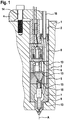
- FIG. 1 An inventive arrangement is exemplary of the Fig. 1 refer to.
- the illustrated arrangement comprises a fuel injector 3, which is received in a bore 2 of a housing part 1 of an internal combustion engine and fixed by means of a clamping claw 4 on the housing part 1.
- the clamping claw 4 is attached thereto by means of a fastening screw 14 on the housing part 1.
- the clamping claw 4 exerts an axial force, the so-called Pratzkraft, on the injector 3, which presses the injector 3 against serving as a support surface 9 paragraph of the bore 2.
- individual components of the injector 3, namely a nozzle body 7, a throttle plate 5, a valve plate 6 and a holding body 8, axially biased against each other.
- the bias in the axial direction causes the components are connected to each other high pressure tight in the range of sealing points 13, since the Pratzkraft the clamping claw 4 due to a non-existing nozzle lock nut also serves as a sealing force.
- Another sealing point 13, which is sealed high-pressure-tight over the Pratzkraft the clamping claw 4 is formed between the nozzle body 7 and the support surface 9 of the housing part 1.
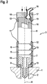
- FIG. 2 An inventive fuel injector is exemplary of Fig. 2 refer to.
- the fuel injector 3 has no nozzle retaining nut, so that other means for axially biasing a nozzle body 7, a throttle plate 5, a valve plate 6 and a holding body 8 are provided against each other.
- These means comprise a plurality of holding devices 10, which are sleeve-shaped or clip-like.
- the clip-type holding devices 10 encompass a component arrangement consisting of nozzle body 7, throttle plate 5, valve plate 6 and holding body 8, so that they ensure cohesion of the component arrangement.
- the clamps are provided on both sides with latching elements 11, which engage in a recess 12 of the injector 3 designed as a circumferential groove or engage behind a shoulder of the injector 3, so that a positive connection is effected in each case.
- a sleeve-shaped or pot-shaped holding device 10 is placed on the nozzle body 7 facing away from the end of the injector 3. Due to the cup shape of the holding device 10 is at the same time a contact surface for the plant of the clamping claw (in Fig. 2 not shown) created on the injector 3.
- the holding device 10 thus serves at the same time as a force transmission member, which the Pratzkraft (see arrows) on the fuel injector 3 transmits.
- the sleeve-shaped or cup-shaped holding device 10 also has a latching element 11, which in the present case has the shape of a radially inwardly extending collar, which is in engagement with a recess 12 designed as a circumferential groove 12 of the injector. Furthermore, the pot-shaped holding device 10 has a bore 17 for carrying out a feed line 16, which is connected to an inlet channel 15 of the injector 3.
- the bore 17 is in the present case designed as a stepped bore, so that over the stage a positive connection with the likewise step-shaped supply line 16 can be produced. In this way, a high pressure-tight connection of the feed line 16 to the inlet channel 15 can be effected via the Pratzkraft (see arrows).
- the connection area thus represents a further sealing point 13.
Landscapes
- Engineering & Computer Science (AREA)
- Chemical & Material Sciences (AREA)
- Combustion & Propulsion (AREA)
- Mechanical Engineering (AREA)
- General Engineering & Computer Science (AREA)
- Manufacturing & Machinery (AREA)
- Fuel-Injection Apparatus (AREA)
Claims (6)
- Agencement comprenant une partie de boîtier (1) d'un moteur à combustion interne avec un alésage (2), un injecteur de carburant (3) reçu au moins en partie dans l'alésage (2) de la partie de boîtier (1) ainsi qu'une griffe de serrage (4) dont la force d'engagement précontraint l'injecteur de carburant (3) dans la direction de son axe longitudinal (A) contre la partie de boîtier (1),
caractérisé en ce que l'injecteur de carburant (3) est supporté directement ou indirectement sur la partie de boîtier (1) et la force d'engagement de la griffe de serrage (4) provoque une connexion étanche aux hautes pressions d'au moins un composant en forme de plaque (5, 6) de l'injecteur de carburant (3) à un corps de buse (7) et/ou un corps de retenue (8) de l'injecteur de carburant (3). - Agencement selon la revendication 1,
caractérisé en ce que l'alésage (2) de la partie de boîtier (1) et/ou la partie de boîtier (1) présente une surface d'appui (9) s'étendant obliquement, notamment radialement, par rapport à l'axe longitudinal (A) en vue du support axial de l'injecteur de carburant (3). - Agencement selon la revendication 1 ou 2, caractérisé en ce qu'au moins un composant en forme de plaque (5, 6) est une plaque d'étranglement (5) et/ou une plaque de soupape (6).
- Injecteur de carburant pour un agencement selon l'une quelconque des revendications précédentes, caractérisé en ce que l'injecteur de carburant (3), pour la connexion temporaire ou durable d'au moins un composant en forme de plaque (5, 6) de l'injecteur de carburant (3) à un corps de buse (7) et/ou un corps de retenue (8) de l'injecteur de carburant (3), comprend un dispositif de retenue (10) pouvant être connecté de préférence de manière amovible à l'injecteur de carburant (3).
- Injecteur de carburant selon la revendication 4, caractérisé en ce que le dispositif de retenue (10) comprend au moins une douille, une pince, un étrier ou similaire et/ou présente au moins un élément d'encliquetage (11) qui peut être amené en prise avec un évidement (12) d'au moins un composant en forme de plaque (5, 6), du corps de buse (7) et/ou du corps de retenue (8).
- Utilisation d'une griffe de serrage (4) pour la fixation d'un injecteur de carburant (3) sur une partie de boîtier (1) d'un moteur à combustion interne, l'injecteur de carburant (3) étant reçu au moins en partie dans un alésage (2) de la partie de boîtier (1) et étant supporté directement ou indirectement sur la partie de boîtier (1), la force d'engagement de la griffe de serrage (4) étant utilisée pour la connexion étanche aux hautes pressions d'au moins un composant en forme de plaque (5, 6) de l'injecteur de carburant (3) à un corps de buse (7) et/ou un corps de retenue (8) de l'injecteur de carburant (3).
Applications Claiming Priority (2)
| Application Number | Priority Date | Filing Date | Title |
|---|---|---|---|
| DE201210205701 DE102012205701A1 (de) | 2012-04-05 | 2012-04-05 | Anordnung umfassend ein Gehäuseteil einer Brennkraftmaschine, einen Kraftstoffinjektor und eine Spannpratze |
| PCT/EP2013/055276 WO2013149799A1 (fr) | 2012-04-05 | 2013-03-14 | Dispositif comprenant une partie de carter d'un moteur à combustion interne, un injecteur de carburant et une griffe de serrage |
Publications (2)
| Publication Number | Publication Date |
|---|---|
| EP2841758A1 EP2841758A1 (fr) | 2015-03-04 |
| EP2841758B1 true EP2841758B1 (fr) | 2016-05-18 |
Family
ID=47878069
Family Applications (1)
| Application Number | Title | Priority Date | Filing Date |
|---|---|---|---|
| EP13709135.1A Not-in-force EP2841758B1 (fr) | 2012-04-05 | 2013-03-14 | Dispositif comprenant une partie de carter d'un moteur à combustion interne, un injecteur de carburant et une griffe de serrage |
Country Status (5)
| Country | Link |
|---|---|
| EP (1) | EP2841758B1 (fr) |
| CN (1) | CN104603446B (fr) |
| DE (1) | DE102012205701A1 (fr) |
| IN (1) | IN2014DN07380A (fr) |
| WO (1) | WO2013149799A1 (fr) |
Families Citing this family (2)
| Publication number | Priority date | Publication date | Assignee | Title |
|---|---|---|---|---|
| DE102012208075A1 (de) * | 2012-05-15 | 2013-11-21 | Man Diesel & Turbo Se | Injektor für eine Kraftstoffversorgungsanlage einer Brennkraftmaschine sowie Kraftstoffversorgungsanlage |
| DE102013018177B4 (de) * | 2013-11-29 | 2016-01-28 | L'orange Gmbh | Kraftstoffinjektormodul sowie Kraftstoffinjektor und Prüfanordnung damit |
Family Cites Families (5)
| Publication number | Priority date | Publication date | Assignee | Title |
|---|---|---|---|---|
| DE19705227A1 (de) * | 1997-02-12 | 1998-08-13 | Bosch Gmbh Robert | Kraftstoffeinspritzventil für Brennkraftmaschinen |
| CN1898046B (zh) * | 2003-12-22 | 2010-12-08 | 本田技研工业株式会社 | 构件的成形方法 |
| DE202006002663U1 (de) | 2006-02-20 | 2006-04-13 | Robert Bosch Gmbh | Kraftstoffinjektor für Brennkraftmaschinen |
| DE102007008146A1 (de) | 2007-02-19 | 2008-08-21 | Robert Bosch Gmbh | Injektor mit Zusatzkörper |
| DE102011078387A1 (de) * | 2011-06-30 | 2013-01-03 | Robert Bosch Gmbh | Kraftstoffinjektor |
-
2012
- 2012-04-05 DE DE201210205701 patent/DE102012205701A1/de not_active Withdrawn
-
2013
- 2013-03-14 IN IN7380DEN2014 patent/IN2014DN07380A/en unknown
- 2013-03-14 WO PCT/EP2013/055276 patent/WO2013149799A1/fr active Application Filing
- 2013-03-14 CN CN201380018468.7A patent/CN104603446B/zh not_active Expired - Fee Related
- 2013-03-14 EP EP13709135.1A patent/EP2841758B1/fr not_active Not-in-force
Also Published As
| Publication number | Publication date |
|---|---|
| IN2014DN07380A (fr) | 2015-04-24 |
| WO2013149799A1 (fr) | 2013-10-10 |
| CN104603446B (zh) | 2018-04-24 |
| DE102012205701A1 (de) | 2013-10-10 |
| CN104603446A (zh) | 2015-05-06 |
| EP2841758A1 (fr) | 2015-03-04 |
Similar Documents
| Publication | Publication Date | Title |
|---|---|---|
| DE102013205340B3 (de) | Montagehilfe für eine Radlagereinheit | |
| AT522050B1 (de) | Flüssigkeitsgekühlte brennkraftmaschine | |
| EP2841756B1 (fr) | Support destiné à fixer un élément sur un moteur à combustion interne | |
| DE19857485A1 (de) | Montagevorrichtung zur Montage und Demontage eines Brennstoffeinspritzventils | |
| EP2321521A1 (fr) | Injecteur de carburant destiné à être disposé sur une chambre de combustion d'un moteur à combustion interne | |
| EP2841758B1 (fr) | Dispositif comprenant une partie de carter d'un moteur à combustion interne, un injecteur de carburant et une griffe de serrage | |
| EP2636911A1 (fr) | Agencement de fixation | |
| EP2664782A1 (fr) | Injecteur pour une installation d'alimentation en carburant d'un moteur à combustion et installation d'alimentation en carburant | |
| DE10256668A1 (de) | Stützelement | |
| EP2905461B1 (fr) | Installation d'injection de carburant dotée d'un composant destiné à guider le carburant, d'une soupape d'injection de carburant et d'un support | |
| DE102011088293B4 (de) | Pratze zum Haltern eines Injektors | |
| AT510318A1 (de) | Zentriervorrichtung für eine kraftstoffeinspritzdüse | |
| DE102005024044A1 (de) | Vorrichtung zur Befestigung eines Kraftstoff einspritzenden Injektors an einer Brennkraftmaschine | |
| DE19807819C1 (de) | Verfahren zur brennraumseitigen Abdichtung eines Einspritzventils einer Brennkraftmaschine | |
| EP2592260A1 (fr) | Injecteur de carburant, procédé de montage d'un injecteur de carburant et dispositif de serrage pour le montage d'un injecteur de carburant | |
| DE102016220395A1 (de) | Dichtungsring für ein Einspritzventil | |
| DE102011017647A1 (de) | Vorrichtung zur Erfassung eines Drucks, insbesondere eines Brennraumdrucks einer Brennkraftmaschine | |
| DE102004036518B4 (de) | Verdrehsichere Dichtkegelverbindung bei Einspritzleitungen zur Kraftstoffeinspritzung und Verfahren zu deren Herstellung | |
| DE102013200922A1 (de) | Brennstoffeinspritzanlage mit einer Brennstoff führenden Komponente, einem Brennstoffeinspritzventil und einer Aufhängung | |
| DE102016201600B4 (de) | Kraftstoffhochdruckpumpe und Kraftstoffeinspritzsystem | |
| DE102021203668A1 (de) | Hochdruckpumpe für ein Kraftstoffeinspritzsystem | |
| DE102021202697A1 (de) | Hochdruckspeicherleitung für ein Kraftstoffeinspritzsystem, Kraftstoffeinspritzsystem sowie Verwendung eines Drosselelements in einer Hochdruckspeicherleitung | |
| DE102014207586A1 (de) | Anschlussstutzen für eine Hochdruckpumpe in einem Kraftstoffeinspritzsystem sowie Hochdruckpumpe mit einem solchen Anschlussstutzen | |
| WO2003025384A1 (fr) | Dispositif de fixation d'injecteurs sur une culasse de cylindre | |
| DE102020215380A1 (de) | Adaptervorrichtung, Fluidleitungsvorrichtung und Kraftstoffeinspritzsystem für ein Fahrzeug |
Legal Events
| Date | Code | Title | Description |
|---|---|---|---|
| PUAI | Public reference made under article 153(3) epc to a published international application that has entered the european phase |
Free format text: ORIGINAL CODE: 0009012 |
|
| 17P | Request for examination filed |
Effective date: 20141105 |
|
| AK | Designated contracting states |
Kind code of ref document: A1 Designated state(s): AL AT BE BG CH CY CZ DE DK EE ES FI FR GB GR HR HU IE IS IT LI LT LU LV MC MK MT NL NO PL PT RO RS SE SI SK SM TR |
|
| AX | Request for extension of the european patent |
Extension state: BA ME |
|
| DAX | Request for extension of the european patent (deleted) | ||
| GRAP | Despatch of communication of intention to grant a patent |
Free format text: ORIGINAL CODE: EPIDOSNIGR1 |
|
| INTG | Intention to grant announced |
Effective date: 20160215 |
|
| GRAS | Grant fee paid |
Free format text: ORIGINAL CODE: EPIDOSNIGR3 |
|
| GRAA | (expected) grant |
Free format text: ORIGINAL CODE: 0009210 |
|
| AK | Designated contracting states |
Kind code of ref document: B1 Designated state(s): AL AT BE BG CH CY CZ DE DK EE ES FI FR GB GR HR HU IE IS IT LI LT LU LV MC MK MT NL NO PL PT RO RS SE SI SK SM TR |
|
| REG | Reference to a national code |
Ref country code: GB Ref legal event code: FG4D Free format text: NOT ENGLISH |
|
| REG | Reference to a national code |
Ref country code: CH Ref legal event code: EP |
|
| REG | Reference to a national code |
Ref country code: IE Ref legal event code: FG4D Free format text: LANGUAGE OF EP DOCUMENT: GERMAN Ref country code: AT Ref legal event code: REF Ref document number: 800710 Country of ref document: AT Kind code of ref document: T Effective date: 20160615 |
|
| REG | Reference to a national code |
Ref country code: DE Ref legal event code: R096 Ref document number: 502013003035 Country of ref document: DE |
|
| REG | Reference to a national code |
Ref country code: NL Ref legal event code: MP Effective date: 20160518 |
|
| REG | Reference to a national code |
Ref country code: LT Ref legal event code: MG4D |
|
| PG25 | Lapsed in a contracting state [announced via postgrant information from national office to epo] |
Ref country code: FI Free format text: LAPSE BECAUSE OF FAILURE TO SUBMIT A TRANSLATION OF THE DESCRIPTION OR TO PAY THE FEE WITHIN THE PRESCRIBED TIME-LIMIT Effective date: 20160518 Ref country code: NO Free format text: LAPSE BECAUSE OF FAILURE TO SUBMIT A TRANSLATION OF THE DESCRIPTION OR TO PAY THE FEE WITHIN THE PRESCRIBED TIME-LIMIT Effective date: 20160818 Ref country code: NL Free format text: LAPSE BECAUSE OF FAILURE TO SUBMIT A TRANSLATION OF THE DESCRIPTION OR TO PAY THE FEE WITHIN THE PRESCRIBED TIME-LIMIT Effective date: 20160518 Ref country code: LT Free format text: LAPSE BECAUSE OF FAILURE TO SUBMIT A TRANSLATION OF THE DESCRIPTION OR TO PAY THE FEE WITHIN THE PRESCRIBED TIME-LIMIT Effective date: 20160518 |
|
| PG25 | Lapsed in a contracting state [announced via postgrant information from national office to epo] |
Ref country code: SE Free format text: LAPSE BECAUSE OF FAILURE TO SUBMIT A TRANSLATION OF THE DESCRIPTION OR TO PAY THE FEE WITHIN THE PRESCRIBED TIME-LIMIT Effective date: 20160518 Ref country code: LV Free format text: LAPSE BECAUSE OF FAILURE TO SUBMIT A TRANSLATION OF THE DESCRIPTION OR TO PAY THE FEE WITHIN THE PRESCRIBED TIME-LIMIT Effective date: 20160518 Ref country code: PT Free format text: LAPSE BECAUSE OF FAILURE TO SUBMIT A TRANSLATION OF THE DESCRIPTION OR TO PAY THE FEE WITHIN THE PRESCRIBED TIME-LIMIT Effective date: 20160919 Ref country code: GR Free format text: LAPSE BECAUSE OF FAILURE TO SUBMIT A TRANSLATION OF THE DESCRIPTION OR TO PAY THE FEE WITHIN THE PRESCRIBED TIME-LIMIT Effective date: 20160819 Ref country code: RS Free format text: LAPSE BECAUSE OF FAILURE TO SUBMIT A TRANSLATION OF THE DESCRIPTION OR TO PAY THE FEE WITHIN THE PRESCRIBED TIME-LIMIT Effective date: 20160518 Ref country code: ES Free format text: LAPSE BECAUSE OF FAILURE TO SUBMIT A TRANSLATION OF THE DESCRIPTION OR TO PAY THE FEE WITHIN THE PRESCRIBED TIME-LIMIT Effective date: 20160518 Ref country code: HR Free format text: LAPSE BECAUSE OF FAILURE TO SUBMIT A TRANSLATION OF THE DESCRIPTION OR TO PAY THE FEE WITHIN THE PRESCRIBED TIME-LIMIT Effective date: 20160518 |
|
| PG25 | Lapsed in a contracting state [announced via postgrant information from national office to epo] |
Ref country code: EE Free format text: LAPSE BECAUSE OF FAILURE TO SUBMIT A TRANSLATION OF THE DESCRIPTION OR TO PAY THE FEE WITHIN THE PRESCRIBED TIME-LIMIT Effective date: 20160518 Ref country code: RO Free format text: LAPSE BECAUSE OF FAILURE TO SUBMIT A TRANSLATION OF THE DESCRIPTION OR TO PAY THE FEE WITHIN THE PRESCRIBED TIME-LIMIT Effective date: 20160518 Ref country code: CZ Free format text: LAPSE BECAUSE OF FAILURE TO SUBMIT A TRANSLATION OF THE DESCRIPTION OR TO PAY THE FEE WITHIN THE PRESCRIBED TIME-LIMIT Effective date: 20160518 Ref country code: SK Free format text: LAPSE BECAUSE OF FAILURE TO SUBMIT A TRANSLATION OF THE DESCRIPTION OR TO PAY THE FEE WITHIN THE PRESCRIBED TIME-LIMIT Effective date: 20160518 Ref country code: DK Free format text: LAPSE BECAUSE OF FAILURE TO SUBMIT A TRANSLATION OF THE DESCRIPTION OR TO PAY THE FEE WITHIN THE PRESCRIBED TIME-LIMIT Effective date: 20160518 |
|
| REG | Reference to a national code |
Ref country code: DE Ref legal event code: R097 Ref document number: 502013003035 Country of ref document: DE |
|
| PG25 | Lapsed in a contracting state [announced via postgrant information from national office to epo] |
Ref country code: PL Free format text: LAPSE BECAUSE OF FAILURE TO SUBMIT A TRANSLATION OF THE DESCRIPTION OR TO PAY THE FEE WITHIN THE PRESCRIBED TIME-LIMIT Effective date: 20160518 Ref country code: SM Free format text: LAPSE BECAUSE OF FAILURE TO SUBMIT A TRANSLATION OF THE DESCRIPTION OR TO PAY THE FEE WITHIN THE PRESCRIBED TIME-LIMIT Effective date: 20160518 |
|
| REG | Reference to a national code |
Ref country code: FR Ref legal event code: PLFP Year of fee payment: 5 |
|
| PLBE | No opposition filed within time limit |
Free format text: ORIGINAL CODE: 0009261 |
|
| STAA | Information on the status of an ep patent application or granted ep patent |
Free format text: STATUS: NO OPPOSITION FILED WITHIN TIME LIMIT |
|
| 26N | No opposition filed |
Effective date: 20170221 |
|
| PG25 | Lapsed in a contracting state [announced via postgrant information from national office to epo] |
Ref country code: SI Free format text: LAPSE BECAUSE OF FAILURE TO SUBMIT A TRANSLATION OF THE DESCRIPTION OR TO PAY THE FEE WITHIN THE PRESCRIBED TIME-LIMIT Effective date: 20160518 |
|
| REG | Reference to a national code |
Ref country code: CH Ref legal event code: PL |
|
| GBPC | Gb: european patent ceased through non-payment of renewal fee |
Effective date: 20170314 |
|
| PG25 | Lapsed in a contracting state [announced via postgrant information from national office to epo] |
Ref country code: MC Free format text: LAPSE BECAUSE OF FAILURE TO SUBMIT A TRANSLATION OF THE DESCRIPTION OR TO PAY THE FEE WITHIN THE PRESCRIBED TIME-LIMIT Effective date: 20160518 |
|
| REG | Reference to a national code |
Ref country code: IE Ref legal event code: MM4A |
|
| PG25 | Lapsed in a contracting state [announced via postgrant information from national office to epo] |
Ref country code: LU Free format text: LAPSE BECAUSE OF NON-PAYMENT OF DUE FEES Effective date: 20170314 |
|
| PG25 | Lapsed in a contracting state [announced via postgrant information from national office to epo] |
Ref country code: GB Free format text: LAPSE BECAUSE OF NON-PAYMENT OF DUE FEES Effective date: 20170314 Ref country code: IE Free format text: LAPSE BECAUSE OF NON-PAYMENT OF DUE FEES Effective date: 20170314 Ref country code: CH Free format text: LAPSE BECAUSE OF NON-PAYMENT OF DUE FEES Effective date: 20170331 Ref country code: LI Free format text: LAPSE BECAUSE OF NON-PAYMENT OF DUE FEES Effective date: 20170331 |
|
| REG | Reference to a national code |
Ref country code: BE Ref legal event code: MM Effective date: 20170331 |
|
| REG | Reference to a national code |
Ref country code: FR Ref legal event code: PLFP Year of fee payment: 6 |
|
| PG25 | Lapsed in a contracting state [announced via postgrant information from national office to epo] |
Ref country code: BE Free format text: LAPSE BECAUSE OF NON-PAYMENT OF DUE FEES Effective date: 20170331 |
|
| PG25 | Lapsed in a contracting state [announced via postgrant information from national office to epo] |
Ref country code: MT Free format text: LAPSE BECAUSE OF FAILURE TO SUBMIT A TRANSLATION OF THE DESCRIPTION OR TO PAY THE FEE WITHIN THE PRESCRIBED TIME-LIMIT Effective date: 20160518 |
|
| PG25 | Lapsed in a contracting state [announced via postgrant information from national office to epo] |
Ref country code: AL Free format text: LAPSE BECAUSE OF FAILURE TO SUBMIT A TRANSLATION OF THE DESCRIPTION OR TO PAY THE FEE WITHIN THE PRESCRIBED TIME-LIMIT Effective date: 20160518 |
|
| PGFP | Annual fee paid to national office [announced via postgrant information from national office to epo] |
Ref country code: FR Payment date: 20190326 Year of fee payment: 7 Ref country code: IT Payment date: 20190321 Year of fee payment: 7 |
|
| REG | Reference to a national code |
Ref country code: AT Ref legal event code: MM01 Ref document number: 800710 Country of ref document: AT Kind code of ref document: T Effective date: 20180314 |
|
| PG25 | Lapsed in a contracting state [announced via postgrant information from national office to epo] |
Ref country code: HU Free format text: LAPSE BECAUSE OF FAILURE TO SUBMIT A TRANSLATION OF THE DESCRIPTION OR TO PAY THE FEE WITHIN THE PRESCRIBED TIME-LIMIT; INVALID AB INITIO Effective date: 20130314 |
|
| PG25 | Lapsed in a contracting state [announced via postgrant information from national office to epo] |
Ref country code: BG Free format text: LAPSE BECAUSE OF FAILURE TO SUBMIT A TRANSLATION OF THE DESCRIPTION OR TO PAY THE FEE WITHIN THE PRESCRIBED TIME-LIMIT Effective date: 20160518 |
|
| PG25 | Lapsed in a contracting state [announced via postgrant information from national office to epo] |
Ref country code: CY Free format text: LAPSE BECAUSE OF FAILURE TO SUBMIT A TRANSLATION OF THE DESCRIPTION OR TO PAY THE FEE WITHIN THE PRESCRIBED TIME-LIMIT Effective date: 20160518 Ref country code: AT Free format text: LAPSE BECAUSE OF NON-PAYMENT OF DUE FEES Effective date: 20180314 |
|
| PG25 | Lapsed in a contracting state [announced via postgrant information from national office to epo] |
Ref country code: MK Free format text: LAPSE BECAUSE OF FAILURE TO SUBMIT A TRANSLATION OF THE DESCRIPTION OR TO PAY THE FEE WITHIN THE PRESCRIBED TIME-LIMIT Effective date: 20160518 |
|
| PG25 | Lapsed in a contracting state [announced via postgrant information from national office to epo] |
Ref country code: TR Free format text: LAPSE BECAUSE OF FAILURE TO SUBMIT A TRANSLATION OF THE DESCRIPTION OR TO PAY THE FEE WITHIN THE PRESCRIBED TIME-LIMIT Effective date: 20160518 |
|
| PG25 | Lapsed in a contracting state [announced via postgrant information from national office to epo] |
Ref country code: IS Free format text: LAPSE BECAUSE OF FAILURE TO SUBMIT A TRANSLATION OF THE DESCRIPTION OR TO PAY THE FEE WITHIN THE PRESCRIBED TIME-LIMIT Effective date: 20160918 |
|
| PG25 | Lapsed in a contracting state [announced via postgrant information from national office to epo] |
Ref country code: FR Free format text: LAPSE BECAUSE OF NON-PAYMENT OF DUE FEES Effective date: 20200331 |
|
| PG25 | Lapsed in a contracting state [announced via postgrant information from national office to epo] |
Ref country code: IT Free format text: LAPSE BECAUSE OF NON-PAYMENT OF DUE FEES Effective date: 20200314 |
|
| PGFP | Annual fee paid to national office [announced via postgrant information from national office to epo] |
Ref country code: DE Payment date: 20220525 Year of fee payment: 10 |
|
| REG | Reference to a national code |
Ref country code: DE Ref legal event code: R119 Ref document number: 502013003035 Country of ref document: DE |
|
| PG25 | Lapsed in a contracting state [announced via postgrant information from national office to epo] |
Ref country code: DE Free format text: LAPSE BECAUSE OF NON-PAYMENT OF DUE FEES Effective date: 20231003 |