EP2840469B1 - Operation input device, operation input method, and program - Google Patents
Operation input device, operation input method, and program Download PDFInfo
- Publication number
- EP2840469B1 EP2840469B1 EP13778112.6A EP13778112A EP2840469B1 EP 2840469 B1 EP2840469 B1 EP 2840469B1 EP 13778112 A EP13778112 A EP 13778112A EP 2840469 B1 EP2840469 B1 EP 2840469B1
- Authority
- EP
- European Patent Office
- Prior art keywords
- region
- coordinate
- contact
- proximity
- touch pad
- Prior art date
- Legal status (The legal status is an assumption and is not a legal conclusion. Google has not performed a legal analysis and makes no representation as to the accuracy of the status listed.)
- Not-in-force
Links
Images


Classifications
-
- G—PHYSICS
- G06—COMPUTING; CALCULATING OR COUNTING
- G06F—ELECTRIC DIGITAL DATA PROCESSING
- G06F3/00—Input arrangements for transferring data to be processed into a form capable of being handled by the computer; Output arrangements for transferring data from processing unit to output unit, e.g. interface arrangements
- G06F3/01—Input arrangements or combined input and output arrangements for interaction between user and computer
- G06F3/03—Arrangements for converting the position or the displacement of a member into a coded form
- G06F3/041—Digitisers, e.g. for touch screens or touch pads, characterised by the transducing means
- G06F3/044—Digitisers, e.g. for touch screens or touch pads, characterised by the transducing means by capacitive means
-
- G—PHYSICS
- G06—COMPUTING; CALCULATING OR COUNTING
- G06F—ELECTRIC DIGITAL DATA PROCESSING
- G06F1/00—Details not covered by groups G06F3/00 - G06F13/00 and G06F21/00
- G06F1/16—Constructional details or arrangements
- G06F1/1613—Constructional details or arrangements for portable computers
- G06F1/1633—Constructional details or arrangements of portable computers not specific to the type of enclosures covered by groups G06F1/1615 - G06F1/1626
- G06F1/1684—Constructional details or arrangements related to integrated I/O peripherals not covered by groups G06F1/1635 - G06F1/1675
- G06F1/169—Constructional details or arrangements related to integrated I/O peripherals not covered by groups G06F1/1635 - G06F1/1675 the I/O peripheral being an integrated pointing device, e.g. trackball in the palm rest area, mini-joystick integrated between keyboard keys, touch pads or touch stripes
-
- G—PHYSICS
- G06—COMPUTING; CALCULATING OR COUNTING
- G06F—ELECTRIC DIGITAL DATA PROCESSING
- G06F3/00—Input arrangements for transferring data to be processed into a form capable of being handled by the computer; Output arrangements for transferring data from processing unit to output unit, e.g. interface arrangements
- G06F3/01—Input arrangements or combined input and output arrangements for interaction between user and computer
- G06F3/03—Arrangements for converting the position or the displacement of a member into a coded form
- G06F3/041—Digitisers, e.g. for touch screens or touch pads, characterised by the transducing means
- G06F3/0416—Control or interface arrangements specially adapted for digitisers
- G06F3/0418—Control or interface arrangements specially adapted for digitisers for error correction or compensation, e.g. based on parallax, calibration or alignment
- G06F3/04186—Touch location disambiguation
-
- G—PHYSICS
- G06—COMPUTING; CALCULATING OR COUNTING
- G06F—ELECTRIC DIGITAL DATA PROCESSING
- G06F2203/00—Indexing scheme relating to G06F3/00 - G06F3/048
- G06F2203/041—Indexing scheme relating to G06F3/041 - G06F3/045
- G06F2203/04108—Touchless 2D- digitiser, i.e. digitiser detecting the X/Y position of the input means, finger or stylus, also when it does not touch, but is proximate to the digitiser's interaction surface without distance measurement in the Z direction
Definitions
- the present invention relates to an operation input device, an operation input method, and a program.
- a touch pad is a pointing device capable of pointing a coordinate by a user performing an operation by making a finger as a pointer in contact with the pad.
- the tip of the thumb is in contact with the touch pad when the operation is initiated.
- the tip of the thumb is gradually warped upward and thus is detached from the touch pad, and the belly of the thumb becomes gradually in contact with the touch pad.
- the tip of the thumb is more warped, and thus the portion of the belly of the thumb in contact with the touch pad approaches toward the base of the thumb.
- the user While moving the thumb in this way, the user has an image such that a fingertip corresponds to the pointed coordinate.
- the actual contact portion of the thumb with the touch pad moves from the fingertip of the thumb to the base side of the belly thereof, and the pointed coordinate detected by the touch pad also moves correspondingly.
- deviation is likely to occur between the operation intended by the user and the pointed coordinate actually detected by the touch pad.
- the sizes and shapes of fingers differ for each user. Further, manners of pushing and moving a finger when manipulating a touch pad also differ for each user. According to this, not only a warping state of the finger when manipulating the touch pad, and a position of the belly of the finger in contact with the touch pad, but also a contact state of the finger on the touch pad, differ for each user.
- the input device described in Japanese Unexamined Patent Application, First Publication No. 2010-204812 calculates the amount of movement of the contact point of the thumb with the touch pad by calculation using the corrected parameter based on a predetermined value.
- a pointed coordinate on the touch pad is obtained by estimation.
- the pointed coordinate is obtained by estimation, there are some cases where in accordance with the difference for each user in contact state of the finger with respect to the touch pad, and it is difficult to appropriately point a coordinate as intended by the user.
- From the EP 2 166 435 an input device is known, where a contact or proximity position is corrected to be closer to a user-intended contact or proximity position.
- a first and a second region is detected based on a 3-value processed proximity value, and the positions of respective centroids of the first region and the second region are calculated to calculate a direction of a straight line connecting the respective centroids.
- the pointed position which is different from the contact or proximity position, is then calculated based on the contact or proximity position and the direction of the straight line connecting the first centroid and the second centroid.
- the US 2013/0132922 disclose an input device, where the undesired proximity detection, the "handshadow error", is compensated for.
- a history profile of data derived from the screen both just prior to, and just after the touch is detected can be processed to compensate for the handshadow effect and to determine a correct touch position value.
- FIG. 1 shows an example of a configuration of a mobile terminal device 100 according to a first embodiment.
- the mobile terminal device 100 shown in this figure includes an operation input unit 101, a control unit 102, a display unit 103, and a communication unit 104.
- the operation input unit (operation input device) 101 outputs a pointed coordinate corresponding to an operation performed on a touch pad by a user. For this reason, the operation input unit 101 includes a touch pad 110, a touch pad interface 120, and a pointed coordinate output unit 130.
- the touch pad (coordinate detecting unit) 110 outputs a detection signal indicating a coordinate corresponding to a contact state of a finger in contact with the touch pad, and a detection signal indicating a coordinate corresponding to a proximity state of the finger in proximity to, without contact with, the touch pad.
- detecting methods for the touch pad 110 for example, an electrostatic capacitance method of detecting electrostatic capacitance generated between a sensor and a finger is known.
- the detecting method for the touch pad in the present embodiment is not particularly limited.
- the touch pad 110 of the present embodiment may be combined with the display unit 103 to become part of a touch pad by which operation on an image displayed on the display unit 103 can be performed.
- the touch pad 110 may be provided on the mobile terminal device 100 as an operation unit independent of the display unit 103.
- the touch pad interface 120 is a unit that inputs and outputs signals to and from the touch pad 110.
- the touch pad interface 120 detects, based on a detection signal output from the touch pad 110, a contact region where a finger is in contact with the touch pad 110, and a proximity region where the finger is in proximity to, without in contact with, the touch pad 110. Additionally, the touch pad interface 120 changes and sets sensitivity of the touch pad 110. Thus, the touch pad 110 switches between normal sensitivity for outputting a detection signal corresponding only to the contact region, and high sensitivity for outputting detection signals corresponding respectively to the contact region and the proximity region.
- the pointed coordinate output unit 130 determines a pointed coordinate based on information concerning only the contact region detected by the touch pad interface 120, or information concerning the contact region and the proximity region which are detected by the touch pad interface 120, and then outputs the determined pointed coordinate.
- the control unit 102 performs control of each unit and various processes in the mobile terminal device 100, and thereby implements the function as the mobile terminal device 100.
- the control unit 102 can be configured to include, for example, a CPU (central processing unit), a main storage device (RAM: random access memory), and an auxiliary storage device (a flash memory, a hard disk, and the like).
- the display unit 103 displays an image in accordance with control by the control unit 102.
- a liquid crystal display device may be used as the display unit 103.
- the communication unit 104 is a unit for communicating with another device via a predetermined communication network.
- the communication unit 104 has a function to communicate with other mobile phones via a telephonic communication network.
- the communication unit 104 has a function to communicate with other mobile terminal devices on the Internet or a LAN (local area network) via, for example, gateways.
- the communication unit 104 has a communication function corresponding to a predetermined short-range wireless communication system.
- FIG. 2 shows an example of a configuration of the operation input unit 101.
- the operation input unit 101 includes the touch pad 110, the touch pad interface 120, and the pointed coordinate output unit 130.
- the touch pad interface 120 includes a region detecting unit 121 and a sensitivity setting unit 122.
- the pointed coordinate output unit 130 includes a region combining unit 131, a determining unit 132, a determination result storing unit 133, and a pointed coordinate determining unit 134.
- the region detecting unit 121 detects, based on a detection signal output from the touch pad 110, a contact region where a finger is in contact with the touch pad 110, and a proximity region where the finger is in proximity to, without contact with, the touch pad 110. As a result of the detection, the region detecting unit 121 outputs information indicating a coordinate of the contact region on the touch pad 110 and a coordinate of the proximity region on the touch pad 110.
- the sensitivity setting unit 122 sets sensitivity of the touch pad 110. As described above, the sensitivity setting unit 122 sets sensitivity of the touch pad 110 so as to switch between the normal sensitivity for outputting a detection signal corresponding only to the contact region, and the high sensitivity for outputting detection signals corresponding respectively to the contact region and the proximity region.
- the high sensitivity is higher than the normal sensitivity.
- the region detecting unit 121 detects only a contact region based on a detection signal output from the touch pad 110. In a case where the high sensitivity is set, the region detecting unit 121 detects a contact region and a proximity region based on a detection signal output from the touch pad 110.
- a change of sensitivity of the touch pad 110 can be realized by, for example, changing a resolution in a two-dimensional direction of a sensor included in the touch pad 110.
- the sensor of the touch pad 110 outputs a detection signal corresponding only to the contact region where a finger is in contact with the touch pad 110.
- the resolution being set to be lower than the normal resolution, the sensor of the touch pad 110 becomes able to output not only a detection signal corresponding to the contact region, but also a detection signal corresponding to a region where the finger is in proximity to, without contact with, the sensor at a distance of up to, for example, approximately 10mm ( i.e., a proximity region).
- the sensitivity of the touch pad 110 becomes high.
- a temporal resolution of the sensor of the touch pad 110 it is also possible to set to the touch pad 110, higher sensitivity than the normal sensitivity.
- a scan frequency of the sensor of the touch pad 110 is set to be lower than the normal frequency.
- the region combining unit 131 included in the pointed coordinate output unit 130 combines a coordinate of the contact region and a coordinate of the proximity region, which are detected separately by the region detecting unit 121. As a result of the combination, the region combining unit 131 generates combined detected region information indicating the coordinate of the contact region and the coordinate of the proximity region.
- the region combining unit 131 outputs, as a result of detection, a normal detected region signal based only on information indicating the coordinate of the contact region output from the touch pad 110.
- the determining unit 132 determines whether or not to use a proximity region in determining a pointed coordinate, based on the area of the contact region detected by the region detecting unit 121.
- the determining unit 132 determines whether or not the area of the contact region is greater than or equal to a threshold value.
- a case where the area of the contact region is greater than or equal to the threshold value corresponds to a case where a finger in contact with the touch pad 110 for operation is the thumb.
- the pointed coordinate determining unit 134 uses the information concerning both the coordinate of the contact region and the coordinate of the proximity region, to determine a pointed coordinate. Therefore, if the area of the contact region is greater than or equal to the threshold value, the determining unit 132 determines to use the proximity region in determining a pointed coordinate.
- a case where the area of the contact region is less than the threshold value corresponds to a case where a finger in contact with the touch pad 110 for operation is the index finger.
- the pointed coordinate determining unit 134 uses only the information concerning the coordinate of the contact region, to determine a pointed coordinate. Therefore, if the area of the contact region is less than the threshold, the determining unit 132 determines not to use the proximity region in determining a pointed coordinate.
- the determination result storing unit 133 stores a result of determination by the determining unit 132. Specifically, if it is determined that the proximity region should be used, the determining unit 132 has the determination result storing unit 133 store determination result information indicating use of the proximity region. Additionally, if it is determined that the proximity region should not be used, the determining unit 132 has the determination result storing unit 133 store determination result information indicating non-use of the proximity region. In such a configuration, the determination result information stored by the determination result storing unit 133 may be 1-bit information indicating either use or non-use of the proximity region.
- the pointed coordinate determining unit 134 determines a pointed coordinate based on any one of the combined detected region information and the normal detected region information which are output by the region combining unit 131.
- the pointed coordinate means a coordinate pointed at by a finger on the touch pad 110.
- the pointed coordinate determining unit 134 determines a pointed coordinate based on the detected contact region and the detected proximity region. Additionally, if it is determined that the proximity region should not be used, the pointed coordinate determining unit 134 determines a pointed coordinate based only on the detected contact region.
- FIGS. 3(a), 3(b), and 3(c) show, from a side surface, a state where the touch pad 110 is manipulated with an index finger 200-f, and also show the region detected by the touch pad 110 at that time.
- the index finger200-f is moving on the touch pad 110 in the direction toward the fingertip thereof (the right direction of the paper), in the order of FIGS. 3(a), 3(b), and 3(c) .
- the index finger 200-f itself is relatively thin. For this reason, as shown in, for example, FIGS. 3(a), 3(b), and 3(c) , the area of a contact region 310 where the belly of the finger is in contact with the touch pad 110 is small. Additionally, in the case of the index finger 200-f, even if the fingertip is moved on the touch pad 110, the index finger 200-f itself is kept standing, and thus the fingertip is likely to be always stably in contact with the touch pad 110.
- the position (coordinate) intended to point at by a user performing operation on the touch pad 110 is a position corresponding to the fingertip thereof.
- the fingertip of the index finger is always in contact with the touch pad 110.
- the position (coordinate) intended by the user to point at on the touch pad 110 is substantially included in the contact region 310 actually detected by the touch pad 110. Therefore, in the case of the index finger, a pointed coordinate may be determined based on information concerning the contact region 310, without using information concerning the proximity region.
- FIGS. 4(a), 4(b), and 4(c) show, from the side surface, a state where the touch pad 110 is manipulated with a thumb 200-t, and also show a region detected by the touch pad 110 at that time. Additionally, the thumb 200-t is moving in the direction toward the fingertip side thereof on the touch pad 110, in the order of FIGS. 4(a), 4(b), and 4(c) .
- the thumb 200-t is considerably thick compared to the index finger 200-f, and accordingly, the belly of the finger is considerably wide. For this reason, as shown in FIGS. 4(a), 4(b), and 4(c) , the area of the contact region 310 where the belly of the thumb 200-t is in contact with the touch pad 110 is also large.
- the contact region 310 actually detected by the touch pad 110 is positioned closer to the base side of the thumb 200-t rather than the fingertip side thereof.
- the position (coordinate) intended by the user to point at on the touch pad 110 is largely deviated from the contact region 310 actually detected by the touch pad 110.
- a portion of the thumb 200-t in proximity to the contact portion is detected as a proximity region 320, even if that portion is not in contact with the touch pad 110.
- a portion of the thumb 200-t in proximity to the tip thereof is also included in the proximity region 320. From this point of view, in the case of the thumb, in order to meet the intention of the user, it is preferable to determine a point in proximity to the tip of the thumb 200-t to be a pointed coordinate 330, using the information concerning the proximity region 320.
- the determining unit 132 determines whether or not to use the proximity region 320 for determination of a pointed coordinate, in accordance with whether the finger manipulating the touch pad 110 is the thumb or the index finger. In other words, if the area of the contact region is less than the threshold value, the determining unit 132 determines not to use the proximity region in accordance with the determination that the finger manipulating the touch pad 110 is the index finger. Additionally, if the area of the contact region detected by the region detecting unit 121 is greater than or equal to the threshold value, the determining unit 132 determines to use the proximity region in accordance with the determination that the finger manipulating the touch pad 110 is the thumb.
- the determining unit 132 instructs the sensitivity setting unit 122 to set the normal sensitivity to the touch pad 110 in accordance with the determination not to use the proximity region.
- the sensitivity setting unit 122 sets the normal sensitivity to the touch pad 110.
- the touch pad 110 is set with normal sensitivity.
- the touch pad 110 set with normal sensitivity detects only the contact region 310 and outputs a detection signal.
- FIG. 5 shows a relationship between a value of the detection signal (detected value) output by the touch pad 110 set with normal sensitivity, and the distance of the finger from a surface of the touch pad 110.
- the touch pad 110 set with the normal sensitivity operates so as to output a detection signal having the maximum value only in the state where the finger is in contact with the surface of the touch pad 110.
- FIG. 6(a) shows, from the side surface, a state where the finger 200 is in contact with the touch pad 110.
- FIG. 6(b) shows the contact region 310 detected by the touch pad 110 set with normal sensitivity in the state shown in FIG. 6(a).
- FIG. 6(c) shows a distribution of the detection signals at the coordinate x1 of the touch pad 110 shown in FIG. 6(b) .
- the touch pad 110 set with the normal sensitivity outputs a detection signal having the maximum value "1.0" in accordance only with the coordinate of the contact region 310 where the finger 200 is in contact with the touch pad 110. Additionally, the touch pad 110 outputs a detection signal having a value "0" in accordance with the coordinate of a region other than the contact region 310, where the finger 200 is not in contact with the touch pad 110.
- the region combining unit 131 in this case receives the detection signal shown in FIG. 6(c) , and detects as the contact region 310, a region at a coordinate where the detected value is, for example, "1.0". Then, the region combining unit 131 outputs information indicating that coordinate, as the normal detected region information.
- the pointed coordinate determining unit 134 receives the normal detected region information and determines a pointed coordinate as follows. In other words, if the normal sensitivity is set, that is, it is determined not to use information concerning the proximity region, the pointed coordinate determining unit 134 determines to be the pointed coordinate 330, the center position of the coordinate range of the contact region 310 indicated by the normal detected region information, as shown in FIG 3 .
- the determining unit 132 instructs the sensitivity setting unit 122 to set high sensitivity to the touch pad 110.
- the sensitivity setting unit 122 sets high sensitivity to the touch pad 110.
- the touch pad 110 is set with high sensitivity.
- FIG. 7 shows a relationship between a value of the detection signal (detected value) output by the touch pad 110 set with high sensitivity, and the distance of the finger from the surface of the touch pad 110.
- the touch pad 110 set with the high sensitivity outputs a detection signal having the value "1.0" (the maximum value), with respect to the contact region 310 where the distance of the finger from the surface of the touch pad 110 is "0". This point is the same as that in the case where the normal sensitivity is set.
- the touch pad 110 outputs a detection signal having a value greater than "0", even if the distance of the finger from the surface of the touch pad is larger than "0", as long as the distance is less than a certain value (for example, approximately 10mm).
- a certain value for example, approximately 10mm.
- the touch pad 110 set with high sensitivity outputs a detection signal corresponding to a portion of the finger present within a given distance from the surface of the touch pad.
- the touch pad 110 can detect a portion of the finger in proximity to the surface of the touch pad.
- FIG. 8(a) shows, from the side surface, a state where the finger 200 is in contact with the touch pad 110.
- FIG. 8b shows the contact region 310 and the proximity region 320 which are detected by the touch pad 110 set with high sensitivity, in the state shown in FIG. 8(a).
- FIG. 8(c) shows a distribution of the detection signals at the coordinate x1 of the touch pad 110 shown in FIG. 8(b) .
- the touch pad 110 outputs a detection signal having the value "1.0" (the maximum value), with respect to the coordinate of the contact region 310 where the finger 200 is in contact with the touch pad 110. Furthermore, in a case where high sensitivity is set, the touch pad 110 also outputs a detection signal corresponding to the coordinate of the proximity region 320 corresponding to the portion of the finger 200 in proximity to, without contact with, the surface of the touch pad.
- the detection signal corresponding to the coordinate of the proximity region 320 is a signal having a value corresponding to the distance from the surface of the touch pad, which is within the range from "0" to "1.0".
- the region detecting unit 121 receives the detected signal shown in FIG. 8(c) , and detects the contact region 310 and the proximity region 320, for example, as follows.
- the region detecting unit 121 receives, as a detection signal, a detected value for each coordinate of the sensor of the touch pad 110. Then, the region detecting unit 121 compares the detection value for each coordinate received to a threshold value th1 set as shown in FIGS. 7 and 8 .
- the threshold value th1 is set so as to distinguish the detection value "1.0" corresponding to the contact region 310 from a detection value less than "1.0" corresponding to the proximity region 320.
- the region detecting unit 121 detects as the contact region 310, a range consisting of coordinates corresponding to the detected values that are greater than or equal to the threshold value th1. Additionally, the region detecting unit 121 detects, as the proximity region 320, a range consisting of coordinates corresponding to the detected values that are greater than "0" and less than the threshold value th1.
- the region combining unit 131 combines the coordinate range of the contact region 310 and the coordinate range of the proximity region 320, which are detected by the region detecting unit 121, to generate and output combined detected region information.
- the combined detected region information is information indicating the coordinate range of the contact region 310 and the coordinate range of the proximity region 320, which are on the touch pad 110.
- the pointed coordinate determining unit 134 determines the pointed coordinate 330. Description will be given with respect to the method of determining the pointed coordinates 330 based on the combined detected region information, while taking first to third examples.
- settings are made with respect to the coordinate of the touch pad 110 such that the origin O(0, 0) represents the coordinate of the position corresponding to the upper left vertex, an x-axis represents a horizontal direction, and a y-axis represents a vertical direction, as shown in FIGS. 9(a), 9(b), and 9(c) .
- the pointed coordinate determining unit 134 of the first example determines the pointed coordinate 330 by the following algorithm.
- the pointed coordinate determining unit 134 specifies a point closest to the origin O from among contact points of y-coordinates (lines in parallel to the x-axis) and the combined detected region 300 including the contact region 310 and the proximity region 320, which are indicated by the combined detected region information.
- FIG. 9 shows a state where a joint of the thumb is stretched in contact with the touch pad 110 while the fingertip of the thumb is oriented substantially directly above.
- a portion in proximity to the fingertip is proximate to the surface of the touch pad and thus is detected as the proximity region 320.
- the contact region 310 is detected corresponding to a portion of the belly of the finger in contact with the surface of the touch pad.
- a portion closer to the base side than the belly of the finger in contact with the surface of the touch pad is also in proximity to, without contact with, the surface of the touch pad, and thus is detected also as the proximity region 320.
- the pointed coordinate 330 determined in this manner is the end portion, on the fingertip side, of the proximity region 320.
- the pointed coordinate 330 corresponds to the position of the fingertip of the thumb in proximity to the surface of the touch pad, without contact with the touch pad 110.
- FIG. 9(b) shows a state where the thumb is standing in contact with the touch pad 110.
- the area of the proximity region 320 in the combined detected region 300 is small.
- the fingertip of the thumb is in contact with the touch pad, the contact region 310 is closer to the fingertip side.
- the pointed coordinate 330 is determined so as to correspond to the position of the end portion, on the fingertip side, of the proximity region 320.
- the pointed coordinate determining method of the first example it is possible to determine to be the pointed coordinate 330, a position corresponding to the end of the fingertip, as long as a user is manipulating the touch pad 110 while directing the fingertip upward.
- FIG. 9(c) shows a state where the thumb is slightly oblique to the touch pad 110.
- the pointed coordinate 330 determined in this manner is deviated slightly from the end of the fingertip, but is the position that can be regarded as substantially the end of the proximity region 320, without any problems.
- the pointed coordinate determination method of the first example it is possible to determine an appropriate pointed coordinate 330 with ignorable errors, as long as the thumb is slightly oblique to the touch pad 110.
- the method of determining the pointed coordinate 330 described with reference to FIG. 9 is effective in the case of an embodiment such that the movement of the finger with respect to the touch pad 110 is substantially along the y-axis. If the method shown FIG. 9 is used under such an embodiment, it is possible to determine a pointed coordinate that meets the intention of the user, with relatively high precision, although the process is simple and the processing load is light. Here, as described with reference to FIG. 9(c) , it is possible to determine a pointed coordinate with little errors even when the thumb is slightly oblique to the touch pad 110.
- pointed coordinate determination method of the second example it is possible to appropriately determine a pointed coordinate whatever direction the finger in contact with the touch pad 110 is directed to.
- FIG. 10(a) shows a state where the thumb is in contact with the touch pad 110 while being tilted in the right oblique direction.
- the pointed coordinate determining unit 134 determines a pointed coordinate by the pointed coordinate determination method of the second example, as follows.
- the pointed coordinate determining unit 134 obtains a center coordinate 311 of the contact region 310 and a center coordinate 321 of the proximity region 320, and then sets a straight line Lc passing the center coordinates 311 and 321.
- the pointed coordinate determining unit 134 obtains one coordinate of the intersection of the straight line Lc and the outer edge of the combined detected region 300 including the contact region 310 and the proximity region 320.
- the combined detected region 300 in FIG. 10 (a) is in a state where a portion of the proximity region 320 on the base side of the thumb is extending to the lower left side of the touch pad 110.
- the pointed coordinate determining unit 134 does not consider to be the outer edge of the combined detected region 300, such a portion of the detected region that has reached the end portion of the touch pad 110, as described above.
- the pointed coordinate determining unit 134 in this case obtains a coordinate of the end portion of the proximity region 320 on the fingertip side, as the coordinate of the intersection of the straight line Lc and the outer edge of the combined detected region 300. Then, the pointed coordinate determining unit 134 determines the coordinate obtained in this manner to be the pointed coordinate 330.
- the pointed coordinate 330 determined by the pointed coordinate determining method of the second example also corresponds to a position of the fingertip of the thumb.
- FIG. 10 (b) shows a state where the thumb is standing in contact with the touch pad 110 so that the area of the contact region 310 in the combined detected region 300 is small.
- the fingertip is an upper right end portion of the outer edge of the combined detected region 300, and the left lower end portion on the opposite side thereof is the side close to the base of the finger. Additionally, the thumb is oblique to the touch pad 110 almost in the lateral direction.
- the pointed coordinate determining unit 134 obtains the coordinate of the intersection of the straight line Lc and the outer edge of the combined detected region 300 by the pointed coordinate determination method of the second example in the case of the state shown in FIG. 10(b) , the coordinates of two points corresponding to the end portion, on the upper right side, of the combined detected region 300 and the end portion, on the lower left side, of the combined detected region 300, are obtained.
- the pointed coordinate determining unit 134 determines to be the pointed coordinate 330, the coordinate closer to the contact region 310.
- the pointed coordinate determining unit 134 can accurately determine the pointed coordinate 330, regardless of the direction of the finger with respect to the touch pad 110.
- the method shown in FIG 10 is a process of determining the intersection of the outer edge of the combined detected region 300 and the straight line Lc passing the center coordinate 311 of the contact region 310 and the center coordinate 321 of the proximity region 320, and therefore the processing load thereof is light.
- the pointed coordinate determining unit 134 using the pointed coordinate determination method of the third example obtains an approximate straight line Ln by approximating, by the least squares method, a group of coordinates corresponding to the combined detected region 300 including the contact region 310 and the proximity region 320, which are indicated by combined detected region information, as shown in FIGS. 11(a) and 11(b) . Then, the pointed coordinate determining unit 134 determines to be the pointed coordinate 330, the intersection of the approximate line Ln and the outer edge of the combined detected region 300.
- the pointed coordinate determination method of the third example similar to the pointed coordinate determination method of the second example, it is possible to appropriately set the pointed coordinate 330, regardless of the direction of the finger to the touch pad 110. Furthermore, in the third example, it is possible to obtain the pointed coordinate 330 at sufficiently high precision by using the least squares method.
- the pointed coordinate determining unit 134 uses all the coordinates forming the combined detected region 300, as shown in FIG. 11(c) .
- the pointed coordinate determining unit 134 may use coordinates extracted at regular intervals from all the coordinates forming the combined detected region 300.
- the pointed coordinate determining unit 134 may use the coordinates of the outer edge of the combined detected region 300 for the least squares method.
- the end portion of the contact region 310 is determined to be the pointed coordinate 330.
- the pointed coordinate 330 is determined so as to correspond to the position of the fingertip. As described above, it is the fingertip that the user manipulating the touch pad 110 is intending to point at. Accordingly, in the present embodiment, it is possible to determine a pointed coordinate as intended by the user.
- the coordinate corresponding to the position of the fingertip is obtained not by estimation, but by directly using the information detected as the proximity region 320.
- the coordinate of the position corresponding to the fingertip is detected in the combined detected region 300, as a pointed coordinate. This is based on the fact that, as described above, the position on the touch pad intended by the user to point at is generally the position of the fingertip.
- the pointed coordinate intended by some users is on the side that is slightly closer to the belly of the finger than the fingertip.
- the pointed coordinate determining unit 134 may determine a pointed coordinate so as to be on the side closer to the belly of the finger, instead of the fingertip.
- the pointed coordinate determining unit 134 determines by, for example, any one of the methods shown in FIGS. 9 to 11 , the pointed coordinate 330 corresponding to the fingertip portion.
- the pointed coordinate 330 in this case is a temporarily determined coordinate.
- the pointed coordinate determining unit 134 obtains a coordinate that internally divides in a predetermined ratio, a line segment connecting the center coordinate 311 of the contact region 310 and the pointed coordinate 330 corresponding to the fingertip portion. Then, the pointed coordinate determining unit 134 determines the coordinate obtained in this manner to be a regular pointed coordinate 330-1.
- the pointed coordinate determining unit 134 calculates the regular pointed coordinate 330-1 by the following calculation for weighted average, where (xc, yc) represents the center coordinate 311 of the contact region 310, (xt, yt) represents the pointed coordinate 330 corresponding to the fingertip portion.
- x , y xt ⁇ 1 ⁇ p + xc ⁇ p , yt ⁇ 1 ⁇ p + yc ⁇ p
- a weighting coefficient p may be optionally set in accordance with user operation.
- the user can modify the degree of moving the pointed coordinate to the base side of the finger, in accordance with preferences or operation feeling of the user, thereby improving the operation feeling.
- the determination of whether to use the information concerning the proximity region 320 for the determination of a pointed coordinate is performed by comparing the threshold value th and the area of the detected contact region 310.
- the determining unit 132 may use the threshold value th as a predetermined fixed value. However, there are individual differences in size of the finger. In accordance with this, a relationship between the area of the region where the thumb is in contact with the touch pad 110 and the area of the region where the index finger is in contact with the touch pad 110 also differs for each user.
- an appropriate value of the threshold th is set for each user, depending on the individual differences in relationship between the area of the region where the thumb is in contact with the touch pad 110 and the area of the region where the index finger is in contact with the touch pad 110.
- the operation input unit 101 may change the threshold value th, for example, as described with reference to FIG. 13 .
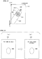
- the touch pad 110 is combined with the display unit 103 to form a touch pad.
- the control unit 102 has the display unit 103 display a window to obtain the area of the contact region 310 of the thumb.
- the user places the thumb on a mark 400 displayed on this window so that the belly side of the thumb is in contact with the mark 400.
- the touch pad 110 outputs a detection signal corresponding to the contact region detected in the mark 400.
- the region detecting unit 121 detects a coordinate range of the contact region.
- the determining unit 132 stores information concerning the coordinate range of the contact region of the thumb detected by the region detecting unit 121.
- control unit 102 has the display unit 103 display a window shown in FIG. 13(b) to obtain the area of the contact region 310 of the index finger.
- the user places the index finger on the mark 400 displayed on this window so that the belly side of the index finger is in contact with the mark 400.
- the determining unit 132 stores information concerning a coordinate range of the contact region of the index finger detected by the region detecting unit 121.
- the determining unit 132 sets a threshold value th using the information concerning the coordinate range of the contact region of the thumb and the information concerning the coordinate range of the contact region of the index finger, which are stored as described above. In other words, based on the area of the region where the thumb is in contact with the touch pad 110 and the area of the region where the index finger is in contact with the touch pad 110, the determining unit 132 sets the threshold value th to be compared with the area of the contact region 310 for the determination of whether or not to use the proximity region 320.
- the determining unit 132 stores the threshold value th calculated in the above manner, and uses the threshold value th for subsequent determination. Thus, in accordance with the size of the finger of the user, the determining unit 132 can appropriately determine whether or not to use information concerning the proximity region 320 (whether the touch pad 110 is manipulated with the thumb or index finger) for the determination of a pointed coordinate.
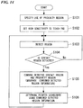
- the flowchart shown in FIG. 14 shows an example of processing procedure for the pointed coordinate determination to be performed by the operation input unit 101.
- the processing shown in this figure is the most fundamental processing of the first embodiment, where high sensitivity is fixedly set to the touch pad 110, and thereby the information concerning the proximity region 320 is constantly used to determine the pointed coordinate 330.
- the determining unit 132 determines that the information concerning the proximity region 320 should be used (step S101). In response to this determination, the determining unit 132 instructs the sensitivity setting unit 122 to set high sensitivity to the touch pad 110 (step S102).
- the region detecting unit 121 detects a region based on a detection signal output from the touch pad 110 (step S103). As a result of the detection of the region, the region detecting unit 121 determines whether or not the contact region 310 is detected (step S104). For this purpose, the region detecting unit 121 may determine, for example, whether there is a coordinate range where a value of the detection signal (detected value) is the maximum value "1.0".
- step S104 NO
- the region detecting unit 121 returns to step S103.
- step S104 YES
- the region detecting unit 121 has detected the proximity region 320 as well as the contact region 310, as described above.
- the region combining unit 131 combines the information concerning the contact region 310 and the information concerning the proximity region 320, which are detected by the region detecting unit 121, and thus generates combined detected region information (step S105).
- the pointed coordinate determining unit 134 determines the pointed coordinate 330 (or the pointed coordinate 330-1) using the generated combined detected region information, by any one of the methods described with reference to FIGS. 9 to 12 (step S106). After the process in step S106 is complete, the processing returns to step S103.
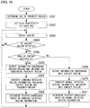
- the flowchart shown in FIG. 15 shows an example of processing procedure for the operation input unit 101 to change the sensitivity of the touch pad 110 and determine a pointed coordinate, in accordance with whether the finger used to manipulate the touch pad 110 is the thumb or the index finger.
- the determining unit 132 unconditionally determines not to use the proximity region 310, regardless of the area of the contact region 310 (step S201). Additionally, in accordance with a result of the determination, the determining unit 132 performs control for setting normal sensitivity to the touch pad 110 (step S202). Further, the determining unit 132 has the determination result storing unit 133 store determination result information indicating non-use of the proximity region as the result of the determination in step S201 (step S203).
- the region detecting unit 121 receives a detection signal output from the touch pad 110 and performs detection of a region (step S204), and as a result of the detection of the region, determines whether or not the contact region 310 is detected (step S205).
- step S205 NO
- the region detecting unit 121 returns to step S204.
- step S205 YES
- the determining unit 132 determines whether or not the area of the detected contact region 310 is greater than or equal to the threshold value th (step S206).
- the determination that the area of the contact region 310 is greater than or equal to the threshold value th corresponds to determination that the proximity region 320 should be used. Additionally, the area of the contact region 310 is less than the threshold value th corresponds to determination that the proximity region 320 should not be used.
- the determining unit 132 determines whether or not the determination result information stored in the determination result storing unit 133 indicates the use of the proximity region (step S207).
- step S207 If the determination result information indicates the use of the proximity region (step S207: YES), the touch pad 110 has already been set with high sensitivity. Therefore, in this case, the processing proceeds to step S211 while skipping steps S208 to S210.
- the touch pad 110 has been set with normal sensitivity.
- the determining unit 132 performs control for setting the high sensitivity to the touch pad 110 (step S208).
- the determining unit 132 has the determination result storing unit 133 store determination result information indicating the use of the proximity region (step S209).
- the determining unit 132 may rewrite the determination result information so far indicating the non-use of the proximity region, with information indicating the use of the proximity region.
- the region detecting unit 121 receives the detection signal output from the touch pad 110, and performs detection of a region again (step S210).
- the region detecting unit 121 detects the coordinate range of the contact region 310 and the coordinate range of the proximity region 320.
- the region combining unit 131 combines the information concerning the contact region 310 and the information concerning the proximity region 320, which are detected by the region detecting unit 121, and thus generates combined detected region information (step S211).
- the pointed coordinate determining unit 134 determines the pointed coordinate 330 (or the pointed coordinate 330-1) using the combined detected region information generated (step S212).
- the determining unit 132 further determines whether or not the determination result information stored in the determination result storing unit 133 indicates the non-use of the proximity region (step S213).
- step S213 If the determination result information indicates the non-use of the proximity region (step S213: YES), the touch pad 110 has already been set with normal sensitivity. For this reason, in this case, the processing proceeds to step S216 while skipping steps S214 to S215.
- the touch pad 110 determines whether the use of the proximity region (step S213: NO). If the determination result information indicates the use of the proximity region (step S213: NO), the touch pad 110 has been set with high sensitivity. For this reason, the determining unit 132 performs control for setting the normal sensitivity to the touch pad 110 (step S214). Additionally, the determining unit 132 rewrites the determination result information stored by the determination result storing unit 133 with information indicating the non-use of the proximity region (step S215). Thus, the touch pad 110 outputs a detection signal corresponding only to the contact region 310, and the region detecting unit 121 operates so as to detect only a coordinate range of the contact region 310.
- the region combining unit 131 generates normal detected region information including only information concerning the contact region 310 detected by the region detecting unit 121 (step S216).
- the pointed coordinate determining unit 134 determines the center position of the contact region 310 to be the pointed coordinate 330, for example, as described with reference to FIG. 3 (step S217).
- step S212 or S217 After the process in step S212 or S217 is complete, the processing returns to step S204.
- processing shown in FIGS. 14 and 15 for example, switching to any one of those processing may be made in accordance with setting operation by the user.
- the configurations of the mobile terminal device 100 and the operation input unit 101 may be similar to those shown in FIGS. 1 and 2 .
- the sensitivity of the touch pad 110 is switched between the high sensitivity and the normal sensitivity, in accordance with the determination of whether or not to use the proximity region 320.
- the high sensitivity is fixedly set to the touch pad 110. Furthermore, if it is determined that the proximity region 320 should be used, the operation input unit 101 determines the pointed coordinate 330 (or the pointed coordinate 330-1) using information concerning the contact region 310 and the proximity region 320. Additionally, if it is determined that the proximity region 320 should not be used, the operation input unit 101 of the second embodiment determines the pointed coordinate 330 (or the pointed coordinate 330-1) using only the information concerning the contact region 310.
- the flowchart shown in FIG. 16 shows an example of processing procedure to be performed for the operation input unit 101 of the second embodiment to determine the pointed coordinate 330.
- the determining unit 132 unconditionally determines to use the proximity region 310 (step S301). Additionally, in accordance with a result of the determination, the determining unit 132 performs control for setting high sensitivity to the touch pad 110 (step S302).
- the region detecting unit 121 receives a detection signal from the touch pad 110 and performs detection of a region (step S303). Since high sensitivity is set to the touch pad 110, the region detecting unit 121 in step S303 detects the contact region 310 and the proximity region 320. Then, as a result of the detection of the region, the region detecting unit 121 determines whether or not the contact region 310 is detected (step S304).
- step S304 NO
- the region detecting unit 121 returns to step S303.
- step S304 determines whether or not the area of the detected contact region 310 is greater than or equal to the threshold th (whether or not to use the information concerning the proximity region 320) (step S305).
- the region detecting unit 121 If it is determined that the area of the contact region 310 is greater than or equal to the threshold value th (the proximity region 320 should be used) (step S305: YES), the region detecting unit 121 outputs information concerning the contact region 310 and information concerning the proximity region 320 (step S306).
- the region combining unit 131 combines the information concerning the contact region 310 and the information concerning the proximity region 320, which are detected by the region detecting unit 121, and thus generates combined detected region information (step S307).
- the pointed coordinate determining unit 134 determines the pointed coordinate 330 (or the pointed coordinate 330-1) using the combined detected region information generated (step S308).
- the region detecting unit 121 outputs only the information concerning the contact region 310 among the information concerning the contact region 310 and the information concerning the proximity region 320 (step S309).
- the region combining unit 131 In response thereto, the region combining unit 131 generates normal detected region information including only the information concerning the contact region 310 (step S310).
- the pointed coordinate determining unit 134 determines the pointed coordinate 330 using the normal detected region information generated (step S311).
- step S308 or S311 After the process in step S308 or S311 is complete, the processing returns to step S303.
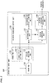
- FIG. 17 shows an example of a configuration of a mobile terminal device 100 according to the third arrangement.
- the same reference numerals are appended to the same portions shown in FIG. 1 , and description thereof is omitted.
- the touch pad 110 is constantly set with normal sensitivity, and thus operates so as to output a detection signal corresponding only to the contact region 310. Furthermore, the mobile terminal device 100 shown in FIG. 17 further includes a proximity region detecting unit 140 in the operation input unit 101.
- the proximity region detecting unit 140 includes a proximity region detecting device 141 and a proximity region detecting device interface 142.
- the proximity region detecting device 141 detects the proximity region 320.
- the proximity region detecting device 141 it is possible to employ an optical sensor for detecting a finger in proximity to the pad surface of the touch pad 110 by detecting light or infrared ray reflected by the finger.
- an optical sensor for detecting a finger in proximity to the pad surface of the touch pad 110 by detecting light or infrared ray reflected by the finger.
- a liquid crystal display device including an optical sensor is known, and such a device can be used as the proximity region detecting device 141.
- the proximity region detecting device 141 it is possible to employ an ultrasonic sensor for detecting the finger in proximity to the pad surface of the touch pad 110 by detecting ultrasonic waves reflected by the finger.
- the proximity region detecting device interface 142 receives a detection signal output from the proximity region detecting device 141 to detect a coordinate range of the proximity region 320.
- the pointed coordinate output unit 130 determines a pointed coordinate using the information concerning the contact region 310 received from the touch pad interface 120, and the information concerning the proximity region 320 received from the proximity region detecting unit 140, and then outputs the determined pointed coordinate.
- FIG. 18 shows an example of a configuration of the operation input unit 101 according to the third arrangement.
- the same reference numerals are appended to the same portions shown in FIG. 2 , and description thereof is omitted.
- the touch pad interface 120 includes only the region detecting unit 121.
- the normal sensitivity is fixedly set to the touch pad 110, and accordingly, the sensitivity setting unit 122 is omitted.
- the region detecting unit 121 of the third embodiment detects only the contact region 310 based on the detection signal output from the touch pad 110 set with the normal sensitivity.
- the proximity region detecting device interface 142 includes a device supporting proximity region detecting unit 142a.
- the device supporting proximity region detecting unit 142a detects a coordinate range of the proximity region 320 based on the detection signal output from the proximity region detecting device 141. Additionally, on-off operation of the device supporting proximity region detecting unit 142a is controlled by the determining unit 132.
- the determining unit 132 performs control for turning on detection operation of the device supporting proximity region detecting unit 142a.
- the region combining unit 131 receives the information concerning the contact region 310 detected by the region detecting unit 121 and the information concerning the proximity region 320 detected by the device supporting proximity region detecting unit 142a, and then generates combined detected region information.
- the pointed coordinate determining unit 134 determines the pointed coordinates 330 (or the pointed coordinate 330-1) using information concerning the coordinate ranges of the contact region 310 and the proximity region 320, which are indicated by the combined detected region information.
- the determining unit 132 performs a control for turning off the detection operation of the device supporting proximity region detecting unit 142a.
- the information concerning the proximity region 320 is not output from the device supporting proximity region detecting unit 142a.
- the region combining unit 131 generates normal detected region information including only the information concerning the contact region 310 detected by the region detecting unit 121.
- the pointed coordinate determining unit 134 determines the pointed coordinate 330 using the information concerning the coordinate range of the contact region 310 indicated by the normal detected region information.
- the flowchart shown in FIG. 19 shows an example of processing procedure to be performed for the operation input unit 101 of the third arrangement to determine a pointed coordinate.
- the determining unit 132 unconditionally determines not to use the proximity region, regardless of the area of the contact region 310 (step S401). Additionally, in accordance with a result of the determination in step S401, the determining unit 132 turns off the detection operation of the device supporting proximity region detecting unit 142a (step S402). Thus, information concerning the proximity region 320 will not be output from the device supporting proximity region detecting unit 142a.
- the determining unit 132 has the determination result storing unit 133 store determination result information indicating the non-use of the proximity region, which is the result of the determination in step S401 (step S403).
- the region detecting unit 121 receives a detection signal output from the touch pad 110 and performs detection of the contact region 310 (step S404).
- the determining unit 132 determines whether or not the determination result information stored in the determination result storing unit 133 indicates the use of the proximity region (step S405).
- step S405 If the determination result information indicates the use of the proximity region (step S405: YES), the detection operation of the device supporting proximity region detecting unit 142a has been turned on. For this reason, the device supporting proximity region detecting unit 142a receives a detection signal from the proximity region detecting device 141, and thus performs detection of the proximity region 320 (step S406).
- step S405 if the determination result information indicates the non-use of the proximity region (step S405: NO), the detection operation of the device supporting proximity region detecting unit 142a has been turned off. Thus, the device supporting proximity region detecting unit 142a in this case does not perform the detection of the proximity region 320 by skipping step S406.
- the region detecting unit 121 determines whether or not the contact region 310 is detected (step S407).
- step S407 NO
- the region detecting unit 121 returns to step S404.
- step S407 YES
- the determining unit 132 determines whether or not the area of the detected contact region 310 is greater than or equal to the threshold value th (step S408).
- the determining unit 132 determines whether or not the determination result information stored in the determination result storing unit 133 indicates the use of the proximity region (step S409).
- step S409 YES
- the detection operation of the device supporting proximity region detecting unit 142a has been turned on. Therefore, in this case, the processing proceeds to step S413 while skipping steps S410 to S412.
- the detection operation of the device supporting proximity region detecting unit 142a has been turned off.
- the determining unit 132 turns on the detection operation of the device supporting proximity region detecting unit 142a (step S410).
- the determining unit 132 rewrites the determination result information stored by the determination result storing unit 133 with information indicating the use of the proximity region (step S411).
- the device supporting proximity region detecting unit 142a receives a detection signal from the proximity region detecting device 141, and performs detection of the proximity region 320 (step S412).
- the region combining unit 131 receives the information concerning the proximity region 320 detected by the device supporting proximity region detecting unit 142a, and the information concerning the contact region 310 detected by the region detecting unit 121.
- the region combining unit 131 combines the information concerning the proximity region 320 detected by the device supporting proximity region detecting unit 142a, and the information concerning the contact region 310 detected by the region detecting unit 121, and thus generates combined detected region information (step S413).
- the pointed coordinate determining unit 134 determines the pointed coordinate 330 (or the pointed coordinate 330-1) using the combined detected region information generated (step S414).
- the determining unit 132 further determines whether or not the determination result information stored in the determination result storing unit 133 indicates the non-use of the proximity region (step S415).
- step S415 If the determination result information indicates the non-use of the proximity region (step S415: YES), the detection operation of the device supporting proximity region detecting unit 142a has already been turned off. For this reason, in this case, the processing proceeds to step S418 while skipping steps S416 to S417.
- step S415 if the determination result information indicates the use of the proximity region (step S415: NO), the detection operation of the device supporting proximity region detecting unit 142a has been turned on. For this reason, the determining unit 132 turns off detection operation of the device supporting proximity region detecting unit 142a (step S416). Additionally, the determining unit 132 rewrites the determination result information stored by the determination result storing unit 133 with information indicating the non-use of the proximity region (step S417). Thus, the device supporting proximity region detecting unit 142a terminates the detection operation. Consequently, the region combining unit 131 receives only the information concerning the contact region 310 detected by the region detecting unit 121.
- the region combining unit 131 generates normal detected region information including only the information concerning the contact region 310 detected by the region detecting unit 121 (step S418).
- the pointed coordinate determining unit 134 determines the center position of the contact region 310 to be the pointed coordinate 330, for example, as described with reference to FIG. 3 (step S419).
- step S414 or S419 After the process in step S414 or S419 is complete, the processing returns to step S404.
- the pointed coordinate may be detected while the device supporting proximity region detecting unit 142a is fixedly turned on.
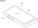
- FIG. 20 shows one example of an embodiment of arrangement of the touch pad 110 of the mobile terminal device 100 of the first and second embodiments.
- the mobile terminal device 100 shown in FIG. 20 has a configuration in which information processing functions are incorporated in a mobile phone, such as a smart phone.
- the touch pad 110 has a rectangular shape with the predetermined width and length, and is provided on a side surface of a housing.
- touch pad 110 With respect to the touch pad 110 provided as shown in FIG. 20 , while carrying the mobile terminal device 100 with the left hand, a user performs manipulation so as to slide the thumb of the same left hand along the direction indicated by an arrow F. Such manipulation on the touch pad 110 is useful to be applied to, for example, a screen scrolling or a volume control, depending on an application running on the mobile terminal device 100.
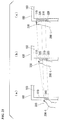
- FIG. 21 shows a relationship among a state of the thumb 200-t, and the contact region 310 and the proximity region 320 which are detected on the touch pad 110, when slide manipulation is performed with the thumb 200-t on the touch pad 110 provided as shown in FIG. 20 .
- the touch pad 110 is assumed to be set with high sensitivity.
- the user performs manipulation so as to slide the thumb 200-t in the direction from the bottom to the top of the touch pad 110, in the order of FIGS. 21(a), 21(b), and 21(c) .
- the touch pad 110 enters a state of outputting a detection signal corresponding to the contact region 310 in a region in proximity to the fingertip of the thumb 200-t.
- FIG. 21(b) shows a state where a certain time has lapsed from the state shown in FIG. 21(a) , and thus the fingertip of the thumb 200-t has been moved to the proximity of the middle of the touch pad 110.
- the first joint of the thumb 200-t has been stretched, and thereby the fingertip of the thumb 200-t is detached from the pad surface of the touch pad 110, and thus the belly of the finger is in contact with the pad surface.
- the touch pad 110 detects the proximity region 320 corresponding to the fingertip side of the thumb 200-t detached from the pad surface, and detects the contact region 310 corresponding to the belly of the thumb 200-t in contact with the pad surface below the proximity region 320. Additionally, the touch pad 110 detects the proximity region 320 corresponding to the base side of the thumb 200-t detached from the pad surface below the contact region 310.
- FIG. 21(c) shows a state where a certain time has further lapsed from the state shown in FIG. 21(b) , and thus the fingertip of the thumb 200-t has been moved to the upper end side of the touch pad 110. At this time, the fingertip of the thumb 200-t is warped upward (in the left direction of the paper) and thus is detached from the pad surface of the touch pad 110, and the belly of the finger on the base side is in contact with the pad surface.
- the touch pad 110 detects the proximity region 320 corresponding to the fingertip side of the thumb 200-t detached from the pad surface, and detects the contact region 310 corresponding to the portion in contact with the belly of the thumb 200-t below the proximity region 320. Further, also in this case, the touch pad 110 detects the proximity region 320 corresponding to the base side of the thumb 200-t detached from the pad surface below the contact region 310.
- the pointed coordinate 330 when the pointed coordinate 330 is determined based only on the contact region 310, the pointed coordinate 330 does not follow the upward movement of the fingertip of the thumb 200-t, and moves only to the middle of the touch pad 110, as can be understood from FIG. 21 .
- the manipulation shown in FIG. 21 is performed such that while holding the mobile terminal device 100 with the left hand, the user slides the thumb 200-t of the same left hand on the touch pad 110.
- the left hand itself cannot be moved in the sliding direction, and the joints of the thumb 200-t are bent or stretched to perform the slide manipulation, thereby making it likely to generate warpage on the fingertip side, as shown in FIG. 21(c) .
- the mobile terminal device 100 of the present embodiment is provided with the operation input unit 101 described so far. For this reason, as shown in FIG. 21 , the pointed coordinate 330 always becomes the position corresponding to the fingertip of the thumb 200-t. Thus, it is possible to obtain the movement of the pointed coordinate, as intended by the user.
- FIG. 22 shows one example of an arrangement of the touch pad 110 of the mobile terminal device 100 of the third arrangement.
- the same reference numerals are appended to the same portions as those shown in FIG. 20 , and description thereof is omitted.
- the touch pad 110 of the mobile terminal device 100 shown in this figure has a rectangular shape, similarly to that shown in FIG. 20 , and is provided on the side surface of the housing. Furthermore, a proximity region detecting device 141 is provided so as to be arranged adjacent and parallel to the touch pad 110 along the direction indicated by an arrow F.
- FIG. 22 shows an example of the arrangement such that the touch pad 110 and the proximity region detecting device 141 are arranged adjacent to each other along the plane direction, in consideration of the intention to clarify the existence of the proximity region detecting device 141.
- the arrangement may be such that the touch pad 110 and the proximity region detecting device 141 overlap each other.
- the operation input unit 101 is applied to the mobile terminal device 100.
- the operation input unit 101 is applicable to devices other than the mobile terminal device, such as a remote control.
- the case where the touch pad 110 is manipulated with the thumb is distinguished from the case where the touch pad 110 is manipulated with the index finger.
- the touch pad 110 is manipulated with, for example, the middle finger.
- the touch pad 110 is manipulated with any one of the fingers other than the thumb, such as the middle finger, the ring finger, and the little finger, these fingers are thin so that it will be determined that manipulation has been performed with the index finger.
- the pointed coordinate 330 is determined similarly to the case where manipulation is performed with the index finger, thus causing no particular inconvenience.
- a program for implementing the functions of each unit shown in FIGS. 2 , 18 , and the like may be recorded on a computer-readable recording medium, so that a computer system can read and execute the program recorded on the recording medium to determine a pointed coordinate.
- the "computer system” may include an OS and hardware such as peripheral devices.
- the "computer system” may include website hosting platform (or display platform) in a case where a WWW system is used.
- the "computer-readable recording medium” means a storage device, such as: a portable medium, for example, a flexible disk, a magneto optical disk, a ROM, or a CD-ROM; or a hard disk built in a computer system.
- the "computer-readable recording medium” may also include a medium that temporarily stores a program, such as a volatile memory included in a computer system which serves as a server or client in a case where the program is transmitted via a network such as the Internet, or a communication line such as a telephone line.
- the above program may be a program for implementing part of the above-described functions. Further, the above program may be a program that can implement the above-described functions in combination with the program already stored in the computer system.
- the present invention is applicable to mobile devices, such as smartphones and tablets.
Landscapes
- Engineering & Computer Science (AREA)
- Theoretical Computer Science (AREA)
- General Engineering & Computer Science (AREA)
- Human Computer Interaction (AREA)
- Physics & Mathematics (AREA)
- General Physics & Mathematics (AREA)
- Computer Hardware Design (AREA)
- Position Input By Displaying (AREA)
- User Interface Of Digital Computer (AREA)
Applications Claiming Priority (2)
| Application Number | Priority Date | Filing Date | Title |
|---|---|---|---|
| JP2012096643A JP5904440B2 (ja) | 2012-04-20 | 2012-04-20 | 操作入力装置、操作入力方法およびプログラム |
| PCT/JP2013/060324 WO2013157400A1 (ja) | 2012-04-20 | 2013-04-04 | 操作入力装置、操作入力方法およびプログラム |
Publications (3)
| Publication Number | Publication Date |
|---|---|
| EP2840469A1 EP2840469A1 (en) | 2015-02-25 |
| EP2840469A4 EP2840469A4 (en) | 2015-12-09 |
| EP2840469B1 true EP2840469B1 (en) | 2018-10-24 |
Family
ID=49383364
Family Applications (1)
| Application Number | Title | Priority Date | Filing Date |
|---|---|---|---|
| EP13778112.6A Not-in-force EP2840469B1 (en) | 2012-04-20 | 2013-04-04 | Operation input device, operation input method, and program |
Country Status (4)
| Country | Link |
|---|---|
| US (1) | US9575604B2 (ja) |
| EP (1) | EP2840469B1 (ja) |
| JP (1) | JP5904440B2 (ja) |
| WO (1) | WO2013157400A1 (ja) |
Families Citing this family (14)
| Publication number | Priority date | Publication date | Assignee | Title |
|---|---|---|---|---|
| KR102056316B1 (ko) * | 2013-05-03 | 2020-01-22 | 삼성전자주식회사 | 터치 스크린 동작 방법 및 그 전자 장치 |
| KR102159789B1 (ko) * | 2013-10-28 | 2020-09-25 | 삼성전자주식회사 | 전자 장치 및 이의 사용자 제스처 인식방법 |
| JP6315443B2 (ja) * | 2014-01-10 | 2018-04-25 | アルパイン株式会社 | 入力装置、マルチタッチ操作の入力検出方法及び入力検出プログラム |
| JP6484859B2 (ja) * | 2014-01-28 | 2019-03-20 | ソニー株式会社 | 情報処理装置、情報処理方法、及びプログラム |
| JP6321387B2 (ja) * | 2014-01-29 | 2018-05-09 | 京セラ株式会社 | 携帯機器、携帯機器のタッチ位置検出方法およびプログラム |
| US9983731B2 (en) * | 2014-02-21 | 2018-05-29 | Qualcomm Incorporated | System and method for reducing shadow effects in touch systems |
| KR20150104302A (ko) * | 2014-03-05 | 2015-09-15 | 삼성전자주식회사 | 전자 장치의 사용자 입력 검출 방법 및 그 전자 장치 |
| JP6324203B2 (ja) | 2014-05-14 | 2018-05-16 | キヤノン株式会社 | 情報処理装置およびその制御方法、プログラム、記録媒体 |
| US9619137B2 (en) * | 2015-03-26 | 2017-04-11 | Motorola Mobility Llc | Portable device touchscreen optimization |
| JP2016197284A (ja) * | 2015-04-02 | 2016-11-24 | 富士通株式会社 | 電子機器、制御方法および制御プログラム |
| TWI592845B (zh) * | 2015-08-28 | 2017-07-21 | 晨星半導體股份有限公司 | 適應性調整觸控閥值的方法與相關控制器 |
| EP3514516B1 (en) * | 2016-09-14 | 2023-10-25 | Sony Group Corporation | Sensor, input device, and electronic device |
| JP6966777B2 (ja) * | 2017-12-06 | 2021-11-17 | 国立大学法人秋田大学 | 入力システム |
| DE102020003923B3 (de) * | 2020-06-30 | 2021-11-04 | Daimler Ag | Bedieneinheit mit einer berührungssensitiven Bedienfläche |
Family Cites Families (15)
| Publication number | Priority date | Publication date | Assignee | Title |
|---|---|---|---|---|
| EP1717681B1 (en) * | 1998-01-26 | 2015-04-29 | Apple Inc. | Method for integrating manual input |
| US20030132922A1 (en) | 2002-01-17 | 2003-07-17 | Harald Philipp | Touch screen detection apparatus |
| KR101060210B1 (ko) * | 2003-02-10 | 2011-08-29 | 엔 트리그 리미티드. | 디지타이저의 접촉 검출 |
| US9019209B2 (en) | 2005-06-08 | 2015-04-28 | 3M Innovative Properties Company | Touch location determination involving multiple touch location processes |
| US20070097096A1 (en) * | 2006-03-25 | 2007-05-03 | Outland Research, Llc | Bimodal user interface paradigm for touch screen devices |
| JP5324440B2 (ja) * | 2006-07-12 | 2013-10-23 | エヌ−トリグ リミテッド | デジタイザのためのホバリングおよびタッチ検出 |
| JP4609557B2 (ja) | 2008-08-29 | 2011-01-12 | ソニー株式会社 | 情報処理装置及び情報処理方法 |
| JP5132604B2 (ja) * | 2009-02-19 | 2013-01-30 | 三菱電機株式会社 | 座標入力装置およびタッチパネル装置 |
| JP2010204812A (ja) * | 2009-03-02 | 2010-09-16 | Panasonic Corp | 携帯端末装置及び入力装置 |
| JP2011053971A (ja) * | 2009-09-02 | 2011-03-17 | Sony Corp | 情報処理装置、情報処理方法およびプログラム |
| JP2011134271A (ja) * | 2009-12-25 | 2011-07-07 | Sony Corp | 情報処理装置、情報処理方法およびプログラム |
| JP5523191B2 (ja) * | 2010-04-30 | 2014-06-18 | 株式会社ジャパンディスプレイ | タッチ検出機能付き表示装置 |
| US8514190B2 (en) * | 2010-10-06 | 2013-08-20 | Sony Corporation | Displays for electronic devices that detect and respond to the contour and/or height profile of user input objects |
| JP5656652B2 (ja) * | 2011-01-07 | 2015-01-21 | キヤノン株式会社 | タッチパネル装置およびタッチパネル検出位置補正方法 |
| US9389716B2 (en) * | 2011-09-23 | 2016-07-12 | Sony Corporation | Mobile terminal apparatus |
-
2012
- 2012-04-20 JP JP2012096643A patent/JP5904440B2/ja active Active
-
2013
- 2013-04-04 US US14/390,795 patent/US9575604B2/en not_active Expired - Fee Related
- 2013-04-04 EP EP13778112.6A patent/EP2840469B1/en not_active Not-in-force
- 2013-04-04 WO PCT/JP2013/060324 patent/WO2013157400A1/ja active Application Filing
Non-Patent Citations (1)
| Title |
|---|
| None * |
Also Published As
| Publication number | Publication date |
|---|---|
| WO2013157400A1 (ja) | 2013-10-24 |
| EP2840469A4 (en) | 2015-12-09 |
| US20150054780A1 (en) | 2015-02-26 |
| EP2840469A1 (en) | 2015-02-25 |
| JP2013225202A (ja) | 2013-10-31 |
| US9575604B2 (en) | 2017-02-21 |
| JP5904440B2 (ja) | 2016-04-13 |
Similar Documents
| Publication | Publication Date | Title |
|---|---|---|
| EP2840469B1 (en) | Operation input device, operation input method, and program | |
| KR101007045B1 (ko) | 접촉센서 장치 및 이 장치의 포인팅 좌표 결정 방법 | |
| KR101534282B1 (ko) | 포터블 디바이스의 사용자 입력 방법 및 상기 사용자 입력 방법이 수행되는 포터블 디바이스 | |
| US10572012B2 (en) | Electronic device for performing gestures and methods for determining orientation thereof | |
| US10073493B2 (en) | Device and method for controlling a display panel | |
| WO2016107257A1 (zh) | 可穿戴设备的屏幕的显示方法及可穿戴设备 | |
| KR20150019352A (ko) | 전자장치에서 그립상태를 인지하기 위한 방법 및 장치 | |
| US20100177121A1 (en) | Information processing apparatus, information processing method, and program | |
| EP2439623B1 (en) | Information processing apparatus including a sensing unit on a side surface and corresponding method | |
| US20100295796A1 (en) | Drawing on capacitive touch screens | |
| JP6000797B2 (ja) | タッチパネル式入力装置、その制御方法、および、プログラム | |
| US20100302152A1 (en) | Data processing device | |
| US20150212724A1 (en) | Manipulation input device, manipulation input method, manipulation input program, and electronic apparatus | |
| US10365748B2 (en) | Smart touch location predictor based on direction vector | |
| JP2010146032A (ja) | 携帯端末装置、及び表示制御方法 | |
| US9213440B2 (en) | System and method for remote touch detection | |
| EP2402844B1 (en) | Electronic devices including interactive displays and related methods and computer program products | |
| AU2015202763B2 (en) | Glove touch detection | |
| JP2011141680A (ja) | 入力装置、入力方法および入力プログラム | |
| US20170075453A1 (en) | Terminal and terminal control method | |
| KR102210045B1 (ko) | 전자장치의 입력 제어장치 및 방법 | |
| KR20140106996A (ko) | 햅틱을 제공하는 방법 및 장치 | |
| WO2014148090A1 (ja) | 情報処理装置及び情報処理方法 | |
| JP5780823B2 (ja) | 表示装置、表示装置の制御方法及びプログラム | |
| KR101880957B1 (ko) | 사용자 중심의 색상 조절이 가능한 전자펜 장치 |
Legal Events
| Date | Code | Title | Description |
|---|---|---|---|
| PUAI | Public reference made under article 153(3) epc to a published international application that has entered the european phase |
Free format text: ORIGINAL CODE: 0009012 |
|
| 17P | Request for examination filed |
Effective date: 20141014 |
|
| AK | Designated contracting states |
Kind code of ref document: A1 Designated state(s): AL AT BE BG CH CY CZ DE DK EE ES FI FR GB GR HR HU IE IS IT LI LT LU LV MC MK MT NL NO PL PT RO RS SE SI SK SM TR |
|
| AX | Request for extension of the european patent |
Extension state: BA ME |
|
| DAX | Request for extension of the european patent (deleted) | ||
| RA4 | Supplementary search report drawn up and despatched (corrected) |
Effective date: 20151106 |
|
| RIC1 | Information provided on ipc code assigned before grant |
Ipc: G06F 3/044 20060101ALI20151102BHEP Ipc: G06F 3/041 20060101AFI20151102BHEP |
|
| GRAP | Despatch of communication of intention to grant a patent |
Free format text: ORIGINAL CODE: EPIDOSNIGR1 |
|
| STAA | Information on the status of an ep patent application or granted ep patent |
Free format text: STATUS: GRANT OF PATENT IS INTENDED |
|
| INTG | Intention to grant announced |
Effective date: 20180530 |
|
| GRAS | Grant fee paid |
Free format text: ORIGINAL CODE: EPIDOSNIGR3 |
|
| GRAA | (expected) grant |
Free format text: ORIGINAL CODE: 0009210 |
|
| STAA | Information on the status of an ep patent application or granted ep patent |
Free format text: STATUS: THE PATENT HAS BEEN GRANTED |
|
| AK | Designated contracting states |
Kind code of ref document: B1 Designated state(s): AL AT BE BG CH CY CZ DE DK EE ES FI FR GB GR HR HU IE IS IT LI LT LU LV MC MK MT NL NO PL PT RO RS SE SI SK SM TR |
|
| REG | Reference to a national code |
Ref country code: CH Ref legal event code: EP |
|
| REG | Reference to a national code |
Ref country code: IE Ref legal event code: FG4D |
|
| REG | Reference to a national code |
Ref country code: AT Ref legal event code: REF Ref document number: 1057439 Country of ref document: AT Kind code of ref document: T Effective date: 20181115 |
|
| REG | Reference to a national code |
Ref country code: DE Ref legal event code: R096 Ref document number: 602013045623 Country of ref document: DE |
|
| REG | Reference to a national code |
Ref country code: NL Ref legal event code: MP Effective date: 20181024 |
|
| REG | Reference to a national code |
Ref country code: LT Ref legal event code: MG4D |
|
| REG | Reference to a national code |
Ref country code: AT Ref legal event code: MK05 Ref document number: 1057439 Country of ref document: AT Kind code of ref document: T Effective date: 20181024 |
|
| PG25 | Lapsed in a contracting state [announced via postgrant information from national office to epo] |
Ref country code: NL Free format text: LAPSE BECAUSE OF FAILURE TO SUBMIT A TRANSLATION OF THE DESCRIPTION OR TO PAY THE FEE WITHIN THE PRESCRIBED TIME-LIMIT Effective date: 20181024 |
|
| PG25 | Lapsed in a contracting state [announced via postgrant information from national office to epo] |
Ref country code: LT Free format text: LAPSE BECAUSE OF FAILURE TO SUBMIT A TRANSLATION OF THE DESCRIPTION OR TO PAY THE FEE WITHIN THE PRESCRIBED TIME-LIMIT Effective date: 20181024 Ref country code: PL Free format text: LAPSE BECAUSE OF FAILURE TO SUBMIT A TRANSLATION OF THE DESCRIPTION OR TO PAY THE FEE WITHIN THE PRESCRIBED TIME-LIMIT Effective date: 20181024 Ref country code: HR Free format text: LAPSE BECAUSE OF FAILURE TO SUBMIT A TRANSLATION OF THE DESCRIPTION OR TO PAY THE FEE WITHIN THE PRESCRIBED TIME-LIMIT Effective date: 20181024 Ref country code: LV Free format text: LAPSE BECAUSE OF FAILURE TO SUBMIT A TRANSLATION OF THE DESCRIPTION OR TO PAY THE FEE WITHIN THE PRESCRIBED TIME-LIMIT Effective date: 20181024 Ref country code: IS Free format text: LAPSE BECAUSE OF FAILURE TO SUBMIT A TRANSLATION OF THE DESCRIPTION OR TO PAY THE FEE WITHIN THE PRESCRIBED TIME-LIMIT Effective date: 20190224 Ref country code: NO Free format text: LAPSE BECAUSE OF FAILURE TO SUBMIT A TRANSLATION OF THE DESCRIPTION OR TO PAY THE FEE WITHIN THE PRESCRIBED TIME-LIMIT Effective date: 20190124 Ref country code: ES Free format text: LAPSE BECAUSE OF FAILURE TO SUBMIT A TRANSLATION OF THE DESCRIPTION OR TO PAY THE FEE WITHIN THE PRESCRIBED TIME-LIMIT Effective date: 20181024 Ref country code: BG Free format text: LAPSE BECAUSE OF FAILURE TO SUBMIT A TRANSLATION OF THE DESCRIPTION OR TO PAY THE FEE WITHIN THE PRESCRIBED TIME-LIMIT Effective date: 20190124 Ref country code: FI Free format text: LAPSE BECAUSE OF FAILURE TO SUBMIT A TRANSLATION OF THE DESCRIPTION OR TO PAY THE FEE WITHIN THE PRESCRIBED TIME-LIMIT Effective date: 20181024 Ref country code: AT Free format text: LAPSE BECAUSE OF FAILURE TO SUBMIT A TRANSLATION OF THE DESCRIPTION OR TO PAY THE FEE WITHIN THE PRESCRIBED TIME-LIMIT Effective date: 20181024 |
|
| PG25 | Lapsed in a contracting state [announced via postgrant information from national office to epo] |
Ref country code: GR Free format text: LAPSE BECAUSE OF FAILURE TO SUBMIT A TRANSLATION OF THE DESCRIPTION OR TO PAY THE FEE WITHIN THE PRESCRIBED TIME-LIMIT Effective date: 20190125 Ref country code: RS Free format text: LAPSE BECAUSE OF FAILURE TO SUBMIT A TRANSLATION OF THE DESCRIPTION OR TO PAY THE FEE WITHIN THE PRESCRIBED TIME-LIMIT Effective date: 20181024 Ref country code: AL Free format text: LAPSE BECAUSE OF FAILURE TO SUBMIT A TRANSLATION OF THE DESCRIPTION OR TO PAY THE FEE WITHIN THE PRESCRIBED TIME-LIMIT Effective date: 20181024 Ref country code: PT Free format text: LAPSE BECAUSE OF FAILURE TO SUBMIT A TRANSLATION OF THE DESCRIPTION OR TO PAY THE FEE WITHIN THE PRESCRIBED TIME-LIMIT Effective date: 20190224 Ref country code: SE Free format text: LAPSE BECAUSE OF FAILURE TO SUBMIT A TRANSLATION OF THE DESCRIPTION OR TO PAY THE FEE WITHIN THE PRESCRIBED TIME-LIMIT Effective date: 20181024 |
|
| REG | Reference to a national code |
Ref country code: DE Ref legal event code: R097 Ref document number: 602013045623 Country of ref document: DE |
|
| PG25 | Lapsed in a contracting state [announced via postgrant information from national office to epo] |
Ref country code: IT Free format text: LAPSE BECAUSE OF FAILURE TO SUBMIT A TRANSLATION OF THE DESCRIPTION OR TO PAY THE FEE WITHIN THE PRESCRIBED TIME-LIMIT Effective date: 20181024 Ref country code: DK Free format text: LAPSE BECAUSE OF FAILURE TO SUBMIT A TRANSLATION OF THE DESCRIPTION OR TO PAY THE FEE WITHIN THE PRESCRIBED TIME-LIMIT Effective date: 20181024 Ref country code: CZ Free format text: LAPSE BECAUSE OF FAILURE TO SUBMIT A TRANSLATION OF THE DESCRIPTION OR TO PAY THE FEE WITHIN THE PRESCRIBED TIME-LIMIT Effective date: 20181024 |
|
| PGFP | Annual fee paid to national office [announced via postgrant information from national office to epo] |
Ref country code: DE Payment date: 20190418 Year of fee payment: 7 |
|
| PG25 | Lapsed in a contracting state [announced via postgrant information from national office to epo] |
Ref country code: SK Free format text: LAPSE BECAUSE OF FAILURE TO SUBMIT A TRANSLATION OF THE DESCRIPTION OR TO PAY THE FEE WITHIN THE PRESCRIBED TIME-LIMIT Effective date: 20181024 Ref country code: RO Free format text: LAPSE BECAUSE OF FAILURE TO SUBMIT A TRANSLATION OF THE DESCRIPTION OR TO PAY THE FEE WITHIN THE PRESCRIBED TIME-LIMIT Effective date: 20181024 Ref country code: EE Free format text: LAPSE BECAUSE OF FAILURE TO SUBMIT A TRANSLATION OF THE DESCRIPTION OR TO PAY THE FEE WITHIN THE PRESCRIBED TIME-LIMIT Effective date: 20181024 Ref country code: SM Free format text: LAPSE BECAUSE OF FAILURE TO SUBMIT A TRANSLATION OF THE DESCRIPTION OR TO PAY THE FEE WITHIN THE PRESCRIBED TIME-LIMIT Effective date: 20181024 |
|
| PGFP | Annual fee paid to national office [announced via postgrant information from national office to epo] |
Ref country code: FR Payment date: 20190424 Year of fee payment: 7 |
|
| PLBE | No opposition filed within time limit |
Free format text: ORIGINAL CODE: 0009261 |
|
| STAA | Information on the status of an ep patent application or granted ep patent |
Free format text: STATUS: NO OPPOSITION FILED WITHIN TIME LIMIT |
|
| 26N | No opposition filed |
Effective date: 20190725 |
|
| PG25 | Lapsed in a contracting state [announced via postgrant information from national office to epo] |
Ref country code: SI Free format text: LAPSE BECAUSE OF FAILURE TO SUBMIT A TRANSLATION OF THE DESCRIPTION OR TO PAY THE FEE WITHIN THE PRESCRIBED TIME-LIMIT Effective date: 20181024 |
|
| PGFP | Annual fee paid to national office [announced via postgrant information from national office to epo] |
Ref country code: GB Payment date: 20190418 Year of fee payment: 7 |
|
| REG | Reference to a national code |
Ref country code: CH Ref legal event code: PL |
|
| REG | Reference to a national code |
Ref country code: BE Ref legal event code: MM Effective date: 20190430 |
|
| PG25 | Lapsed in a contracting state [announced via postgrant information from national office to epo] |
Ref country code: LU Free format text: LAPSE BECAUSE OF NON-PAYMENT OF DUE FEES Effective date: 20190404 Ref country code: MC Free format text: LAPSE BECAUSE OF FAILURE TO SUBMIT A TRANSLATION OF THE DESCRIPTION OR TO PAY THE FEE WITHIN THE PRESCRIBED TIME-LIMIT Effective date: 20181024 |
|
| PG25 | Lapsed in a contracting state [announced via postgrant information from national office to epo] |
Ref country code: LI Free format text: LAPSE BECAUSE OF NON-PAYMENT OF DUE FEES Effective date: 20190430 Ref country code: CH Free format text: LAPSE BECAUSE OF NON-PAYMENT OF DUE FEES Effective date: 20190430 |
|
| PG25 | Lapsed in a contracting state [announced via postgrant information from national office to epo] |
Ref country code: BE Free format text: LAPSE BECAUSE OF NON-PAYMENT OF DUE FEES Effective date: 20190430 |
|
| PG25 | Lapsed in a contracting state [announced via postgrant information from national office to epo] |
Ref country code: TR Free format text: LAPSE BECAUSE OF FAILURE TO SUBMIT A TRANSLATION OF THE DESCRIPTION OR TO PAY THE FEE WITHIN THE PRESCRIBED TIME-LIMIT Effective date: 20181024 |
|
| PG25 | Lapsed in a contracting state [announced via postgrant information from national office to epo] |
Ref country code: IE Free format text: LAPSE BECAUSE OF NON-PAYMENT OF DUE FEES Effective date: 20190404 |
|
| REG | Reference to a national code |
Ref country code: DE Ref legal event code: R119 Ref document number: 602013045623 Country of ref document: DE |
|
| PG25 | Lapsed in a contracting state [announced via postgrant information from national office to epo] |
Ref country code: DE Free format text: LAPSE BECAUSE OF NON-PAYMENT OF DUE FEES Effective date: 20201103 Ref country code: FR Free format text: LAPSE BECAUSE OF NON-PAYMENT OF DUE FEES Effective date: 20200430 |
|
| GBPC | Gb: european patent ceased through non-payment of renewal fee |
Effective date: 20200404 |
|
| PG25 | Lapsed in a contracting state [announced via postgrant information from national office to epo] |
Ref country code: GB Free format text: LAPSE BECAUSE OF NON-PAYMENT OF DUE FEES Effective date: 20200404 |
|
| PG25 | Lapsed in a contracting state [announced via postgrant information from national office to epo] |
Ref country code: CY Free format text: LAPSE BECAUSE OF FAILURE TO SUBMIT A TRANSLATION OF THE DESCRIPTION OR TO PAY THE FEE WITHIN THE PRESCRIBED TIME-LIMIT Effective date: 20181024 |
|
| PG25 | Lapsed in a contracting state [announced via postgrant information from national office to epo] |
Ref country code: MT Free format text: LAPSE BECAUSE OF FAILURE TO SUBMIT A TRANSLATION OF THE DESCRIPTION OR TO PAY THE FEE WITHIN THE PRESCRIBED TIME-LIMIT Effective date: 20181024 Ref country code: HU Free format text: LAPSE BECAUSE OF FAILURE TO SUBMIT A TRANSLATION OF THE DESCRIPTION OR TO PAY THE FEE WITHIN THE PRESCRIBED TIME-LIMIT; INVALID AB INITIO Effective date: 20130404 |
|
| PG25 | Lapsed in a contracting state [announced via postgrant information from national office to epo] |
Ref country code: MK Free format text: LAPSE BECAUSE OF FAILURE TO SUBMIT A TRANSLATION OF THE DESCRIPTION OR TO PAY THE FEE WITHIN THE PRESCRIBED TIME-LIMIT Effective date: 20181024 |