EP2840377A1 - Procédé et dispositif de test d'un élément de construction plat relatif à la résistance à la pression - Google Patents
Procédé et dispositif de test d'un élément de construction plat relatif à la résistance à la pression Download PDFInfo
- Publication number
- EP2840377A1 EP2840377A1 EP13181135.8A EP13181135A EP2840377A1 EP 2840377 A1 EP2840377 A1 EP 2840377A1 EP 13181135 A EP13181135 A EP 13181135A EP 2840377 A1 EP2840377 A1 EP 2840377A1
- Authority
- EP
- European Patent Office
- Prior art keywords
- pressure
- shut
- component
- pressure chamber
- fluid
- Prior art date
- Legal status (The legal status is an assumption and is not a legal conclusion. Google has not performed a legal analysis and makes no representation as to the accuracy of the status listed.)
- Granted
Links
- 238000000034 method Methods 0.000 title claims abstract description 21
- 238000012360 testing method Methods 0.000 title claims abstract description 17
- 238000010276 construction Methods 0.000 title description 2
- 239000012530 fluid Substances 0.000 claims abstract description 33
- 230000000903 blocking effect Effects 0.000 claims abstract description 3
- 230000001066 destructive effect Effects 0.000 claims description 5
- 230000002441 reversible effect Effects 0.000 claims description 3
- 238000012546 transfer Methods 0.000 claims description 3
- 230000035939 shock Effects 0.000 description 12
- 229910000831 Steel Inorganic materials 0.000 description 11
- 239000010959 steel Substances 0.000 description 11
- 238000004880 explosion Methods 0.000 description 7
- 238000010998 test method Methods 0.000 description 5
- 239000002360 explosive Substances 0.000 description 4
- 210000002445 nipple Anatomy 0.000 description 4
- 238000009826 distribution Methods 0.000 description 3
- 238000005474 detonation Methods 0.000 description 2
- 238000002474 experimental method Methods 0.000 description 2
- 230000001105 regulatory effect Effects 0.000 description 2
- 238000007789 sealing Methods 0.000 description 2
- 238000004088 simulation Methods 0.000 description 2
- 125000006850 spacer group Chemical group 0.000 description 2
- 101100049938 Neurospora crassa (strain ATCC 24698 / 74-OR23-1A / CBS 708.71 / DSM 1257 / FGSC 987) exr-1 gene Proteins 0.000 description 1
- 238000005422 blasting Methods 0.000 description 1
- 238000009434 installation Methods 0.000 description 1
- 238000004904 shortening Methods 0.000 description 1
- 238000007655 standard test method Methods 0.000 description 1
- 230000008961 swelling Effects 0.000 description 1
- 238000012549 training Methods 0.000 description 1
- 238000003466 welding Methods 0.000 description 1
Images
Classifications
-
- G—PHYSICS
- G01—MEASURING; TESTING
- G01M—TESTING STATIC OR DYNAMIC BALANCE OF MACHINES OR STRUCTURES; TESTING OF STRUCTURES OR APPARATUS, NOT OTHERWISE PROVIDED FOR
- G01M7/00—Vibration-testing of structures; Shock-testing of structures
- G01M7/08—Shock-testing
-
- G—PHYSICS
- G01—MEASURING; TESTING
- G01N—INVESTIGATING OR ANALYSING MATERIALS BY DETERMINING THEIR CHEMICAL OR PHYSICAL PROPERTIES
- G01N3/00—Investigating strength properties of solid materials by application of mechanical stress
- G01N3/30—Investigating strength properties of solid materials by application of mechanical stress by applying a single impulsive force, e.g. by falling weight
Definitions
- the present invention relates to a device with which the aforementioned method can be carried out.
- planar components are understood as meaning all components which can be used for enclosing rooms. For example, count to flat construction elements doors, gates and windows of any kind and facade, wall or roof structures and parts thereof.
- the second standard test method is the explosion pressure test on the shock pipe, the test procedure of which is regulated in DIN EN 13124-1.
- the classification of the tested bodies is specified in DIN EN 13123-1.
- a pipe about 50 m in length with a diameter of about 2 m to 3 m is divided into two areas by means of a steel sheet clamped over the diameter, wherein in the region of the shock pipe facing away from the test piece, which is called pressure pipe, a pressure is built, while in the test body facing the region of the shock tube is ambient pressure.
- the two areas dividing steel sheet is provided with an explosive charge (eg X-shaped detonating cord), which is ignited after sufficient pressure build-up in the pressure tube, so destroyed by the blasting of the steel sheet and thereby a connecting cross-section of the pressure tube to the component associated with the pipe section is created.
- an explosive charge eg X-shaped detonating cord
- This method allows compared to the field trial and the shock tube attempt a much cheaper and space-saving test procedure.
- the method allows the simulation of various pressure loads, but it requires a great skill for setting a pressure distribution. In particular, it is difficult to limit the pressure distribution to an extremely short period of time, such as the duration of only 20 milliseconds.
- the shut-off device according to the present invention is non-destructive and reversibly operable, which means that after generation of the pressure load after different periods of time after the opening time and optionally at different speeds or slowly closed again. In this way, different courses of a pressure load (peak pressure, pressure gradient, load duration, etc.) can be simulated.
- the pressure distribution over time can vary widely with different explosions. While a petrochemical explosion at the beginning of a pressure of about 50 kPa is present, which subsided after 150 ms, resulting in a TNT explosion, an initial pressure of about 200 kPa, which drops to zero already after about 25 ms. In the case of earthquakes, which can also be simulated by the method, earth movements typically occur over a period of several seconds or even a few minutes to hours, stressing components.
- the present invention to discharge fluid from the pressure chamber during the pressure action on the component.
- the reflected pressure may escape from the pressure chamber, thereby shortening the exposure time of the pressure.
- the discharge of the fluid may be provided so that a certain proportion of the fluid escapes before the pressure peak forming acts on the device.
- the discharge of the fluid during the entire time of pressure on the device can take place or only during a time interval.
- the starting time of the time interval should preferably be after a start time, at which the shut-off of the shut-off is transferred to the open position and its end time preferably before or after a closing time, to which the shut-off of the shut-off is returned to the closed position.
- the flow direction of the fluid should deviate from the flow direction of the fluid in an opening into the pressure chamber opening cross-section of the connecting line at the exit from the discharge opening.
- the direction of the flow of the fluid should preferably extend perpendicular to a stress level defined by the component at the exit from the discharge opening.
- the above object is achieved by a device according to the O-term of claim 4, wherein the shut-off non-destructive from the closed position to the open position and vice versa can be transferred and the shut-off device is arranged in the at least one connecting line, wherein at least one pressure chamber communicating with the environment discharge opening is present.
- the method described above can be carried out in a particularly simple manner, wherein the advantages described with regard to the method also apply to the device.
- the device can also be used to check the connection situation of the component to a component surrounded masonry or surrounding the component concrete wall or similar parts of buildings on their pressure resistance.
- the masonry, the concrete wall or similar parts of buildings can be checked for his or her own pressure resistance.
- the at least one relief opening preferably a plurality of relief openings
- the at least one relief opening is or are arranged in at least one end face connecting the wall to the frame, preferably in a plurality of end faces.
- the arrangement of the relief openings in the end faces is advantageous because the fluid flows, which act on the one hand on the building under test and on the other to escape from the pressure chamber, do not interfere with each other or collide.
- a relief cross section of the at least one relief opening can be aligned parallel to the loading plane.
- An embodiment of the device according to the invention has quarter-circle in cross-section deflecting elements, with which a parallel to the load plane directed flow of the fluid can be deflected by 90 ° in a direction perpendicular to the load plane flow, preferably a tangential plane to a deflecting element with the load level or one of Front sides of the frame leg formed frame plane coincides.
- the relief valve which selectively opens or closes the at least one relief opening is provided, which preferably only permits a pressure relief of the chamber.
- the relief valve may be formed as a check valve.
- the check valve may also be designed as a flap valve.
- a simple flap may also be arranged on the relief cross-section, which allows the fluid to escape.
- a screw-on cover is conceivable.
- a length of the associated relief opening measured parallel to the respective frame leg has at least 50%, preferably at least 70%, preferably at least 80%, of the corresponding parallel length of the component.
- the size of the at least one discharge opening can be adjusted. This can preferably be done by means of a sliding element or a removable cover element, which covers the discharge opening at different levels.
- the area of a relief cross-section formed by the relief opening is between 50 cm 2 and 100 cm 2 , preferably between 200 cm 2 and 1000 cm 2 . It is also advantageous if the relief cross section can be varied, so that it can be adjusted individually to the desired requirements with respect to the pressure duration and the exposure interval.
- a minimum distance between an opening cross-section of the connecting line between the pressure vessel and the pressure chamber and a discharge opening is at least 10 mm, preferably 40 mm.
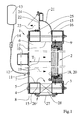
- FIG. 1 is a horizontal section through a pressure chamber 6 of a device 1 according to the invention for testing the resistance of a designed as a steel security door component 2 against pressure.
- the device 1 comprises a holding frame 3, which is composed of four frame legs each in the form of a square tube.
- the steel security door is attached with anchor-like fastening means, which will not be discussed in detail here, circumferentially on the support frame 3.
- the holding frame 3 is connected by means of distributed over its circumference screws 4 with a wall 5, which is arranged at a distance parallel to the holding frame 3.
- a chamber frame 7 is arranged, which is positioned in alignment with the holding frame 3 and is constructed analogously to the holding frame 3.
- Holding frame 3 and chamber frame 7 have a clear distance from each other, which corresponds approximately to the diameter of a square tube of the holding frame 3 and chamber frame 7.
- a pressure chamber 6 is provided which has a depth T corresponding to the depth of the two-chamber chamber 7 with built-steel security door, ie with a chamber frame 7 of 120 mm, the depth T of the pressure chamber is 240 mm.
- a sealing strip 8 is provided circumferentially in a thickness of 3 mm.
- a flat profile 9 is circumferentially provided on the side facing away from the chamber frame 7 side of the support frame 3, which is outwardly aligned with the support frame 3 and projecting inwardly over the support frame 3 and in the event of failure of the fasteners throwing away the device. 2 would prevent from the support frame 3.
- the rear wall of the pressure chamber 6 forming wall 5, which is formed by a 10 mm thick steel plate is reinforced on its side facing away from the pressure chamber 6 with horizontally across the width of the device 1 extending profiles 10, which are formed of tubular steel profiles , wherein superimposed profiles 10 have a clearance of 120 mm from each other.
- the profiles 10 are edge welded over their entire length with the back of the wall 5 point.
- the wall 5 has three spaced weld nipple 11, of which in the FIG. 1 only one is shown.
- a connecting line 12 is in each case shot to a pressure vessel 13, which supplies the pressure chamber 6 with the pressure provided for carrying out a test.
- the connecting lines 12 may be pipelines and / or hoses, which are either fed by the pressure vessel 13 in each case, or are initially led together to form a supply line, the supply line leading to the pressure vessel 13, which in this case is a single Shut-off 14 contains.
- either all connecting lines 12 or the supply line have a shut-off element 14, for example in the form of a ball valve, by means of which the supply of the pressure chamber 6 can be initiated with pressure, stopped or re-initiated.
- a shut-off element 14 or the shut-off elements Before carrying out a test pressure is generated in the pressure vessel 13, for example via a compressor, not shown, and after reaching the required Pressure the shut-off element 14 or the shut-off elements open, so that in the pressure chamber 6, the pressure wave of an explosion is simulated.
- the device 1 according to the FIG. 1 has a relief opening 15 located on a first lateral face 16 of the device 1 and forming a relief cross-section 17 aligned parallel to a loading plane 18, the loading plane 18 being defined as the plane of the device 2 to which the pressure wave , which is indicated by arrows 19, impinges, ie in the FIG. 1 the pressure chamber 6 facing surface 20 of the security door.
- the device 1 In the region of the discharge opening 15, the device 1 is provided with a quarter-circle in cross-section deflection element 21, with which the flow of the fluid exiting the pressure chamber 6 - starting from an orientation parallel to the load plane 18 - is deflected by 90 degrees, so that the one Outlet opening 22 leaving fluid, which is indicated by an arrow 23, is aligned parallel to the incident on the load plane 18 pressure.
- the fluid emerging from the outlet opening 22 is aligned in the opposite direction to the pressure wave acting on the component 2.
- the outlet opening 22 is provided with a pivotable flap 24, wherein a stop 25 of the flap 24 is variable in its length, so that the size of the cross section of the outlet opening 22 is variable.
- the flap 24 and the stop 25 are each shown in a dotted line in an open position or in an extended position. To obtain the extended position, the angle formed stop 25, which is secured with a screw, can be replaced by an angle with other leg length.
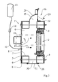
- the device 1 is also provided with a discharge opening 15, in front of which a pressure discharge plate 27 is mounted.
- the pressure discharge plate 27 is provided in some areas with respect to their size and number of different openings that can be covered or uncovered to regulate the pressure reduction, which is the FIG. 1 in detail is not apparent.
- the device 1 is analogous to the device 1 according to the FIG. 1 equipped at its first lateral end face 16 with a discharge opening 15 with a quarter-circle in cross-section deflection element 21, wherein the outlet opening 22 is not - as in the FIG. 1 to the side facing away from the component 2, but towards the side facing the component 2, so that the fluid leaving the outlet opening 22, which is indicated by an arrow 29, flows parallel and in the same direction as the pressure wave; which acts on the component 2 and is indicated by the arrows 19.
- the latter is equipped with at least one pressure sensor, not shown, the recorded data for control purposes are detected by a control unit, also not shown.
- the control times for various test procedures can be stored, which may differ with respect to the maximum pressure, the pressure gradient in the swelling and decay phase, the pulse, the duration of action and the opening or closing of the discharge openings.
Priority Applications (1)
| Application Number | Priority Date | Filing Date | Title |
|---|---|---|---|
| EP13181135.8A EP2840377B1 (fr) | 2013-08-21 | 2013-08-21 | Procédé et dispositif de test d'un élément de construction plat relatif à la résistance à la pression |
Applications Claiming Priority (1)
| Application Number | Priority Date | Filing Date | Title |
|---|---|---|---|
| EP13181135.8A EP2840377B1 (fr) | 2013-08-21 | 2013-08-21 | Procédé et dispositif de test d'un élément de construction plat relatif à la résistance à la pression |
Publications (2)
| Publication Number | Publication Date |
|---|---|
| EP2840377A1 true EP2840377A1 (fr) | 2015-02-25 |
| EP2840377B1 EP2840377B1 (fr) | 2016-09-21 |
Family
ID=49000851
Family Applications (1)
| Application Number | Title | Priority Date | Filing Date |
|---|---|---|---|
| EP13181135.8A Active EP2840377B1 (fr) | 2013-08-21 | 2013-08-21 | Procédé et dispositif de test d'un élément de construction plat relatif à la résistance à la pression |
Country Status (1)
| Country | Link |
|---|---|
| EP (1) | EP2840377B1 (fr) |
Cited By (2)
| Publication number | Priority date | Publication date | Assignee | Title |
|---|---|---|---|---|
| CN105043704A (zh) * | 2015-03-12 | 2015-11-11 | 哈尔滨工程大学 | 一种横向冲击强化型半潜式浮动冲击平台 |
| CN107478396A (zh) * | 2017-08-17 | 2017-12-15 | 福建省永正工程质量检测有限公司 | 一种建筑门窗检测系统 |
Citations (4)
| Publication number | Priority date | Publication date | Assignee | Title |
|---|---|---|---|---|
| US3248924A (en) * | 1961-11-22 | 1966-05-03 | William W Boynton | System for dynamic loading |
| US5197323A (en) * | 1990-07-13 | 1993-03-30 | Sparta, Inc. | Pebble-bed heater and shock tube assembly |
| WO2011104126A1 (fr) * | 2010-02-23 | 2011-09-01 | Antonio Fidelibus | Chambre d'essai pour produits résistants à l'explosion |
| EP2645076A1 (fr) * | 2012-03-28 | 2013-10-02 | Sälzer Sicherheitstechnik GmbH | Procédé et dispositif de test d'un élément de construction plat relatif à la résistance à la pression |
-
2013
- 2013-08-21 EP EP13181135.8A patent/EP2840377B1/fr active Active
Patent Citations (4)
| Publication number | Priority date | Publication date | Assignee | Title |
|---|---|---|---|---|
| US3248924A (en) * | 1961-11-22 | 1966-05-03 | William W Boynton | System for dynamic loading |
| US5197323A (en) * | 1990-07-13 | 1993-03-30 | Sparta, Inc. | Pebble-bed heater and shock tube assembly |
| WO2011104126A1 (fr) * | 2010-02-23 | 2011-09-01 | Antonio Fidelibus | Chambre d'essai pour produits résistants à l'explosion |
| EP2645076A1 (fr) * | 2012-03-28 | 2013-10-02 | Sälzer Sicherheitstechnik GmbH | Procédé et dispositif de test d'un élément de construction plat relatif à la résistance à la pression |
Non-Patent Citations (2)
| Title |
|---|
| PFB: "Das PfB hat für die Zukunft vorgesorgt", PFB FLYER, January 2015 (2015-01-01), XP055279812 |
| RUDOLF STUMBERGER: "Ingenieure zwischen Technik und Ethik", VDI NACHRICHTEN, 4 March 2016 (2016-03-04), pages 30, XP055279810 |
Cited By (3)
| Publication number | Priority date | Publication date | Assignee | Title |
|---|---|---|---|---|
| CN105043704A (zh) * | 2015-03-12 | 2015-11-11 | 哈尔滨工程大学 | 一种横向冲击强化型半潜式浮动冲击平台 |
| CN105043704B (zh) * | 2015-03-12 | 2018-06-12 | 哈尔滨工程大学 | 一种横向冲击强化型半潜式浮动冲击平台 |
| CN107478396A (zh) * | 2017-08-17 | 2017-12-15 | 福建省永正工程质量检测有限公司 | 一种建筑门窗检测系统 |
Also Published As
| Publication number | Publication date |
|---|---|
| EP2840377B1 (fr) | 2016-09-21 |
Similar Documents
| Publication | Publication Date | Title |
|---|---|---|
| EP2645076B1 (fr) | Procédé et dispositif de test d'un élément de construction plat relatif à la résistance à la pression | |
| DE2639691A1 (de) | Tuerartiger verschluss | |
| DE3705401C2 (fr) | ||
| DE3728332C2 (fr) | ||
| EP2840377B1 (fr) | Procédé et dispositif de test d'un élément de construction plat relatif à la résistance à la pression | |
| DE202012013273U1 (de) | Vorrichtung zum Testen eines flächigen Bauelements bezüglich Beständigkeit gegenüber Druckeinwirkung | |
| DE202013012235U1 (de) | Vorrichtung zum Testen eines flächigen Bauelements bezüglich Beständigkeit gegenüber Druckeinwirkung | |
| EP2759657B1 (fr) | Banc d'essai pour portes, fenêtres et façades | |
| DE102011053560A1 (de) | Brandschutzsystem sowie Brandschutztür, Brandschutz-Wandelement und Brandschutzplatte hierfür | |
| DE10354680A1 (de) | Verfahren zum Verbinden von sich zumindest teilweise überlappenden Bauteilen | |
| EP3626890B1 (fr) | Procédé d'essai de portance d'une fondation | |
| DE202015002648U1 (de) | Führungsblech zum Einbau von Einbauteilen | |
| DE2452745A1 (de) | Verfahren zum auseinanderbrechen von gegenstaenden, insbesondere beton, gesteinsbloecken, maschinen und motoren sowie anlage zur ausfuehrung des verfahrens | |
| DE10235614A1 (de) | Revisionsklappe | |
| DE3140043A1 (de) | Brandschutzklappe | |
| DE202008005092U1 (de) | Vorrichtung zur Druckentlastung | |
| DE102010027368A1 (de) | Vorrichtung zur Eckbefestigung einer Leibungsplatte | |
| DE102011001987A1 (de) | Verfahren und Vorrichtung zum Einschließen eines Bohrlochs | |
| DE102015102444B4 (de) | Verfahren und Vorrichtung zur Bestimmung der Schwenkstellung einer Vorpfändkappe | |
| EP1978200A1 (fr) | Façade avec montants et traverses de type résistante aux explosions | |
| WO2005078214A1 (fr) | Batiments | |
| DE202015004791U1 (de) | Simulatoren für Unterrichts- oder Ausbildungszwecke Türen/ Fenster oder ähnliche Abschlüsse für besondere Zwecke | |
| EP1959073A1 (fr) | Composant léger destiné à la construction d'un renforcement de mur à partir d'objets existants, ainsi que renforcement de mur en composants légers | |
| DE1908383A1 (de) | Druckventil fuer Schutzraeume | |
| DE2953638C2 (fr) |
Legal Events
| Date | Code | Title | Description |
|---|---|---|---|
| REG | Reference to a national code |
Ref country code: DE Ref legal event code: R138 Ref document number: 202013012235 Country of ref document: DE Free format text: GERMAN DOCUMENT NUMBER IS 502013004655 |
|
| PUAI | Public reference made under article 153(3) epc to a published international application that has entered the european phase |
Free format text: ORIGINAL CODE: 0009012 |
|
| 17P | Request for examination filed |
Effective date: 20130821 |
|
| AK | Designated contracting states |
Kind code of ref document: A1 Designated state(s): AL AT BE BG CH CY CZ DE DK EE ES FI FR GB GR HR HU IE IS IT LI LT LU LV MC MK MT NL NO PL PT RO RS SE SI SK SM TR |
|
| AX | Request for extension of the european patent |
Extension state: BA ME |
|
| R17P | Request for examination filed (corrected) |
Effective date: 20150820 |
|
| RBV | Designated contracting states (corrected) |
Designated state(s): AL AT BE BG CH CY CZ DE DK EE ES FI FR GB GR HR HU IE IS IT LI LT LU LV MC MK MT NL NO PL PT RO RS SE SI SK SM TR |
|
| RIC1 | Information provided on ipc code assigned before grant |
Ipc: G01N 3/30 20060101ALN20151221BHEP Ipc: G01N 3/313 20060101ALN20151221BHEP Ipc: G01M 7/08 20060101AFI20151221BHEP Ipc: G01N 3/10 20060101ALI20151221BHEP Ipc: H01R 31/00 20060101ALI20151221BHEP |
|
| GRAP | Despatch of communication of intention to grant a patent |
Free format text: ORIGINAL CODE: EPIDOSNIGR1 |
|
| RIC1 | Information provided on ipc code assigned before grant |
Ipc: G01M 7/08 20060101AFI20160413BHEP Ipc: G01N 3/30 20060101ALN20160413BHEP Ipc: H01R 31/00 20060101ALI20160413BHEP Ipc: G01N 3/10 20060101ALI20160413BHEP Ipc: G01N 3/313 20060101ALN20160413BHEP |
|
| INTG | Intention to grant announced |
Effective date: 20160425 |
|
| TPAC | Observations filed by third parties |
Free format text: ORIGINAL CODE: EPIDOSNTIPA |
|
| RIC1 | Information provided on ipc code assigned before grant |
Ipc: G01M 7/08 20060101AFI20160608BHEP Ipc: G01N 3/313 20060101ALN20160608BHEP Ipc: G01N 3/30 20060101ALN20160608BHEP Ipc: H01R 31/00 20060101ALI20160608BHEP Ipc: G01N 3/10 20060101ALI20160608BHEP |
|
| GRAS | Grant fee paid |
Free format text: ORIGINAL CODE: EPIDOSNIGR3 |
|
| GRAP | Despatch of communication of intention to grant a patent |
Free format text: ORIGINAL CODE: EPIDOSNIGR1 |
|
| GRAA | (expected) grant |
Free format text: ORIGINAL CODE: 0009210 |
|
| INTC | Intention to grant announced (deleted) | ||
| RIC1 | Information provided on ipc code assigned before grant |
Ipc: G01N 3/313 20060101ALN20160728BHEP Ipc: G01N 3/30 20060101ALN20160728BHEP Ipc: G01N 3/10 20060101ALI20160728BHEP Ipc: G01M 7/08 20060101AFI20160728BHEP Ipc: H01R 31/00 20060101ALI20160728BHEP |
|
| INTG | Intention to grant announced |
Effective date: 20160811 |
|
| AK | Designated contracting states |
Kind code of ref document: B1 Designated state(s): AL AT BE BG CH CY CZ DE DK EE ES FI FR GB GR HR HU IE IS IT LI LT LU LV MC MK MT NL NO PL PT RO RS SE SI SK SM TR |
|
| REG | Reference to a national code |
Ref country code: GB Ref legal event code: FG4D Free format text: NOT ENGLISH |
|
| REG | Reference to a national code |
Ref country code: CH Ref legal event code: EP |
|
| REG | Reference to a national code |
Ref country code: AT Ref legal event code: REF Ref document number: 831436 Country of ref document: AT Kind code of ref document: T Effective date: 20161015 |
|
| REG | Reference to a national code |
Ref country code: IE Ref legal event code: FG4D Free format text: LANGUAGE OF EP DOCUMENT: GERMAN |
|
| REG | Reference to a national code |
Ref country code: DE Ref legal event code: R096 Ref document number: 502013004655 Country of ref document: DE |
|
| REG | Reference to a national code |
Ref country code: LT Ref legal event code: MG4D Ref country code: NL Ref legal event code: MP Effective date: 20160921 |
|
| PG25 | Lapsed in a contracting state [announced via postgrant information from national office to epo] |
Ref country code: NO Free format text: LAPSE BECAUSE OF FAILURE TO SUBMIT A TRANSLATION OF THE DESCRIPTION OR TO PAY THE FEE WITHIN THE PRESCRIBED TIME-LIMIT Effective date: 20161221 Ref country code: RS Free format text: LAPSE BECAUSE OF FAILURE TO SUBMIT A TRANSLATION OF THE DESCRIPTION OR TO PAY THE FEE WITHIN THE PRESCRIBED TIME-LIMIT Effective date: 20160921 Ref country code: FI Free format text: LAPSE BECAUSE OF FAILURE TO SUBMIT A TRANSLATION OF THE DESCRIPTION OR TO PAY THE FEE WITHIN THE PRESCRIBED TIME-LIMIT Effective date: 20160921 Ref country code: LT Free format text: LAPSE BECAUSE OF FAILURE TO SUBMIT A TRANSLATION OF THE DESCRIPTION OR TO PAY THE FEE WITHIN THE PRESCRIBED TIME-LIMIT Effective date: 20160921 |
|
| PG25 | Lapsed in a contracting state [announced via postgrant information from national office to epo] |
Ref country code: LV Free format text: LAPSE BECAUSE OF FAILURE TO SUBMIT A TRANSLATION OF THE DESCRIPTION OR TO PAY THE FEE WITHIN THE PRESCRIBED TIME-LIMIT Effective date: 20160921 Ref country code: GR Free format text: LAPSE BECAUSE OF FAILURE TO SUBMIT A TRANSLATION OF THE DESCRIPTION OR TO PAY THE FEE WITHIN THE PRESCRIBED TIME-LIMIT Effective date: 20161222 Ref country code: NL Free format text: LAPSE BECAUSE OF FAILURE TO SUBMIT A TRANSLATION OF THE DESCRIPTION OR TO PAY THE FEE WITHIN THE PRESCRIBED TIME-LIMIT Effective date: 20160921 Ref country code: SE Free format text: LAPSE BECAUSE OF FAILURE TO SUBMIT A TRANSLATION OF THE DESCRIPTION OR TO PAY THE FEE WITHIN THE PRESCRIBED TIME-LIMIT Effective date: 20160921 |
|
| PG25 | Lapsed in a contracting state [announced via postgrant information from national office to epo] |
Ref country code: EE Free format text: LAPSE BECAUSE OF FAILURE TO SUBMIT A TRANSLATION OF THE DESCRIPTION OR TO PAY THE FEE WITHIN THE PRESCRIBED TIME-LIMIT Effective date: 20160921 Ref country code: RO Free format text: LAPSE BECAUSE OF FAILURE TO SUBMIT A TRANSLATION OF THE DESCRIPTION OR TO PAY THE FEE WITHIN THE PRESCRIBED TIME-LIMIT Effective date: 20160921 |
|
| PG25 | Lapsed in a contracting state [announced via postgrant information from national office to epo] |
Ref country code: PL Free format text: LAPSE BECAUSE OF FAILURE TO SUBMIT A TRANSLATION OF THE DESCRIPTION OR TO PAY THE FEE WITHIN THE PRESCRIBED TIME-LIMIT Effective date: 20160921 Ref country code: SM Free format text: LAPSE BECAUSE OF FAILURE TO SUBMIT A TRANSLATION OF THE DESCRIPTION OR TO PAY THE FEE WITHIN THE PRESCRIBED TIME-LIMIT Effective date: 20160921 Ref country code: BG Free format text: LAPSE BECAUSE OF FAILURE TO SUBMIT A TRANSLATION OF THE DESCRIPTION OR TO PAY THE FEE WITHIN THE PRESCRIBED TIME-LIMIT Effective date: 20161221 Ref country code: ES Free format text: LAPSE BECAUSE OF FAILURE TO SUBMIT A TRANSLATION OF THE DESCRIPTION OR TO PAY THE FEE WITHIN THE PRESCRIBED TIME-LIMIT Effective date: 20160921 Ref country code: CZ Free format text: LAPSE BECAUSE OF FAILURE TO SUBMIT A TRANSLATION OF THE DESCRIPTION OR TO PAY THE FEE WITHIN THE PRESCRIBED TIME-LIMIT Effective date: 20160921 Ref country code: SK Free format text: LAPSE BECAUSE OF FAILURE TO SUBMIT A TRANSLATION OF THE DESCRIPTION OR TO PAY THE FEE WITHIN THE PRESCRIBED TIME-LIMIT Effective date: 20160921 Ref country code: IS Free format text: LAPSE BECAUSE OF FAILURE TO SUBMIT A TRANSLATION OF THE DESCRIPTION OR TO PAY THE FEE WITHIN THE PRESCRIBED TIME-LIMIT Effective date: 20170121 Ref country code: PT Free format text: LAPSE BECAUSE OF FAILURE TO SUBMIT A TRANSLATION OF THE DESCRIPTION OR TO PAY THE FEE WITHIN THE PRESCRIBED TIME-LIMIT Effective date: 20170123 |
|
| REG | Reference to a national code |
Ref country code: DE Ref legal event code: R097 Ref document number: 502013004655 Country of ref document: DE |
|
| PG25 | Lapsed in a contracting state [announced via postgrant information from national office to epo] |
Ref country code: IT Free format text: LAPSE BECAUSE OF FAILURE TO SUBMIT A TRANSLATION OF THE DESCRIPTION OR TO PAY THE FEE WITHIN THE PRESCRIBED TIME-LIMIT Effective date: 20160921 |
|
| PLBE | No opposition filed within time limit |
Free format text: ORIGINAL CODE: 0009261 |
|
| STAA | Information on the status of an ep patent application or granted ep patent |
Free format text: STATUS: NO OPPOSITION FILED WITHIN TIME LIMIT |
|
| PG25 | Lapsed in a contracting state [announced via postgrant information from national office to epo] |
Ref country code: DK Free format text: LAPSE BECAUSE OF FAILURE TO SUBMIT A TRANSLATION OF THE DESCRIPTION OR TO PAY THE FEE WITHIN THE PRESCRIBED TIME-LIMIT Effective date: 20160921 |
|
| 26N | No opposition filed |
Effective date: 20170622 |
|
| PG25 | Lapsed in a contracting state [announced via postgrant information from national office to epo] |
Ref country code: SI Free format text: LAPSE BECAUSE OF FAILURE TO SUBMIT A TRANSLATION OF THE DESCRIPTION OR TO PAY THE FEE WITHIN THE PRESCRIBED TIME-LIMIT Effective date: 20160921 |
|
| REG | Reference to a national code |
Ref country code: CH Ref legal event code: PL |
|
| PG25 | Lapsed in a contracting state [announced via postgrant information from national office to epo] |
Ref country code: MC Free format text: LAPSE BECAUSE OF FAILURE TO SUBMIT A TRANSLATION OF THE DESCRIPTION OR TO PAY THE FEE WITHIN THE PRESCRIBED TIME-LIMIT Effective date: 20160921 |
|
| PG25 | Lapsed in a contracting state [announced via postgrant information from national office to epo] |
Ref country code: LI Free format text: LAPSE BECAUSE OF NON-PAYMENT OF DUE FEES Effective date: 20170831 Ref country code: CH Free format text: LAPSE BECAUSE OF NON-PAYMENT OF DUE FEES Effective date: 20170831 |
|
| REG | Reference to a national code |
Ref country code: FR Ref legal event code: ST Effective date: 20180430 |
|
| REG | Reference to a national code |
Ref country code: IE Ref legal event code: MM4A |
|
| REG | Reference to a national code |
Ref country code: BE Ref legal event code: MM Effective date: 20170831 |
|
| PG25 | Lapsed in a contracting state [announced via postgrant information from national office to epo] |
Ref country code: LU Free format text: LAPSE BECAUSE OF NON-PAYMENT OF DUE FEES Effective date: 20170821 |
|
| PG25 | Lapsed in a contracting state [announced via postgrant information from national office to epo] |
Ref country code: IE Free format text: LAPSE BECAUSE OF NON-PAYMENT OF DUE FEES Effective date: 20170821 |
|
| PG25 | Lapsed in a contracting state [announced via postgrant information from national office to epo] |
Ref country code: BE Free format text: LAPSE BECAUSE OF NON-PAYMENT OF DUE FEES Effective date: 20170831 Ref country code: FR Free format text: LAPSE BECAUSE OF NON-PAYMENT OF DUE FEES Effective date: 20170831 |
|
| PG25 | Lapsed in a contracting state [announced via postgrant information from national office to epo] |
Ref country code: MT Free format text: LAPSE BECAUSE OF FAILURE TO SUBMIT A TRANSLATION OF THE DESCRIPTION OR TO PAY THE FEE WITHIN THE PRESCRIBED TIME-LIMIT Effective date: 20160921 |
|
| PG25 | Lapsed in a contracting state [announced via postgrant information from national office to epo] |
Ref country code: AL Free format text: LAPSE BECAUSE OF FAILURE TO SUBMIT A TRANSLATION OF THE DESCRIPTION OR TO PAY THE FEE WITHIN THE PRESCRIBED TIME-LIMIT Effective date: 20160921 |
|
| PG25 | Lapsed in a contracting state [announced via postgrant information from national office to epo] |
Ref country code: HU Free format text: LAPSE BECAUSE OF FAILURE TO SUBMIT A TRANSLATION OF THE DESCRIPTION OR TO PAY THE FEE WITHIN THE PRESCRIBED TIME-LIMIT; INVALID AB INITIO Effective date: 20130821 |
|
| REG | Reference to a national code |
Ref country code: AT Ref legal event code: MM01 Ref document number: 831436 Country of ref document: AT Kind code of ref document: T Effective date: 20180821 |
|
| PG25 | Lapsed in a contracting state [announced via postgrant information from national office to epo] |
Ref country code: CY Free format text: LAPSE BECAUSE OF FAILURE TO SUBMIT A TRANSLATION OF THE DESCRIPTION OR TO PAY THE FEE WITHIN THE PRESCRIBED TIME-LIMIT Effective date: 20160921 |
|
| PG25 | Lapsed in a contracting state [announced via postgrant information from national office to epo] |
Ref country code: MK Free format text: LAPSE BECAUSE OF FAILURE TO SUBMIT A TRANSLATION OF THE DESCRIPTION OR TO PAY THE FEE WITHIN THE PRESCRIBED TIME-LIMIT Effective date: 20160921 |
|
| PG25 | Lapsed in a contracting state [announced via postgrant information from national office to epo] |
Ref country code: AT Free format text: LAPSE BECAUSE OF NON-PAYMENT OF DUE FEES Effective date: 20180821 |
|
| PG25 | Lapsed in a contracting state [announced via postgrant information from national office to epo] |
Ref country code: TR Free format text: LAPSE BECAUSE OF FAILURE TO SUBMIT A TRANSLATION OF THE DESCRIPTION OR TO PAY THE FEE WITHIN THE PRESCRIBED TIME-LIMIT Effective date: 20160921 |
|
| PG25 | Lapsed in a contracting state [announced via postgrant information from national office to epo] |
Ref country code: HR Free format text: LAPSE BECAUSE OF FAILURE TO SUBMIT A TRANSLATION OF THE DESCRIPTION OR TO PAY THE FEE WITHIN THE PRESCRIBED TIME-LIMIT Effective date: 20160921 |
|
| REG | Reference to a national code |
Ref country code: DE Ref legal event code: R082 Ref document number: 502013004655 Country of ref document: DE Representative=s name: PATENT- UND RECHTSANWAELTE LOESENBECK, SPECHT,, DE Ref country code: DE Ref legal event code: R082 Ref document number: 502013004655 Country of ref document: DE Representative=s name: BAUER WAGNER PELLENGAHR SROKA PATENT- & RECHTS, DE |
|
| REG | Reference to a national code |
Ref country code: DE Ref legal event code: R082 Ref document number: 502013004655 Country of ref document: DE Representative=s name: PATENT- UND RECHTSANWAELTE LOESENBECK, SPECHT,, DE |
|
| P01 | Opt-out of the competence of the unified patent court (upc) registered |
Effective date: 20230818 |
|
| PGFP | Annual fee paid to national office [announced via postgrant information from national office to epo] |
Ref country code: GB Payment date: 20230728 Year of fee payment: 11 |
|
| PGFP | Annual fee paid to national office [announced via postgrant information from national office to epo] |
Ref country code: DE Payment date: 20230728 Year of fee payment: 11 |