EP2840007B1 - Konsistente Verhaltenserzeugung eines erweiterten vorhersagbaren Fahrerhilfssystems - Google Patents
Konsistente Verhaltenserzeugung eines erweiterten vorhersagbaren Fahrerhilfssystems Download PDFInfo
- Publication number
- EP2840007B1 EP2840007B1 EP13181312.3A EP13181312A EP2840007B1 EP 2840007 B1 EP2840007 B1 EP 2840007B1 EP 13181312 A EP13181312 A EP 13181312A EP 2840007 B1 EP2840007 B1 EP 2840007B1
- Authority
- EP
- European Patent Office
- Prior art keywords
- signal
- decision
- activation signal
- vehicle
- activation
- Prior art date
- Legal status (The legal status is an assumption and is not a legal conclusion. Google has not performed a legal analysis and makes no representation as to the accuracy of the status listed.)
- Active
Links
- 230000004913 activation Effects 0.000 claims description 114
- 238000000034 method Methods 0.000 claims description 51
- 238000011156 evaluation Methods 0.000 claims description 50
- 230000006641 stabilisation Effects 0.000 claims description 43
- 238000011105 stabilization Methods 0.000 claims description 38
- 230000008859 change Effects 0.000 claims description 31
- 230000000087 stabilizing effect Effects 0.000 claims description 24
- 230000002123 temporal effect Effects 0.000 claims description 9
- 238000004422 calculation algorithm Methods 0.000 claims description 8
- 230000009471 action Effects 0.000 claims description 7
- 238000007635 classification algorithm Methods 0.000 claims description 7
- 230000003044 adaptive effect Effects 0.000 claims description 6
- 238000012706 support-vector machine Methods 0.000 claims description 3
- 230000006399 behavior Effects 0.000 description 39
- 230000006870 function Effects 0.000 description 13
- 238000001514 detection method Methods 0.000 description 11
- 238000012545 processing Methods 0.000 description 10
- 230000006978 adaptation Effects 0.000 description 5
- 238000004891 communication Methods 0.000 description 4
- 238000004590 computer program Methods 0.000 description 4
- 230000004044 response Effects 0.000 description 4
- 230000000875 corresponding effect Effects 0.000 description 3
- 230000000694 effects Effects 0.000 description 3
- 230000003466 anti-cipated effect Effects 0.000 description 2
- 238000013459 approach Methods 0.000 description 2
- 238000010586 diagram Methods 0.000 description 2
- 238000001914 filtration Methods 0.000 description 2
- 230000008569 process Effects 0.000 description 2
- 230000001953 sensory effect Effects 0.000 description 2
- 230000003068 static effect Effects 0.000 description 2
- 241001465754 Metazoa Species 0.000 description 1
- 230000001133 acceleration Effects 0.000 description 1
- 230000008901 benefit Effects 0.000 description 1
- 230000001276 controlling effect Effects 0.000 description 1
- 230000002596 correlated effect Effects 0.000 description 1
- 230000009849 deactivation Effects 0.000 description 1
- 230000007613 environmental effect Effects 0.000 description 1
- 238000003384 imaging method Methods 0.000 description 1
- 230000007257 malfunction Effects 0.000 description 1
- 238000005259 measurement Methods 0.000 description 1
- 230000000116 mitigating effect Effects 0.000 description 1
- 238000010295 mobile communication Methods 0.000 description 1
- 230000008447 perception Effects 0.000 description 1
- 230000003334 potential effect Effects 0.000 description 1
- 230000002265 prevention Effects 0.000 description 1
- 238000012502 risk assessment Methods 0.000 description 1
- 239000007787 solid Substances 0.000 description 1
- 230000009466 transformation Effects 0.000 description 1
- 230000001960 triggered effect Effects 0.000 description 1
Images


Classifications
-
- B—PERFORMING OPERATIONS; TRANSPORTING
- B60—VEHICLES IN GENERAL
- B60W—CONJOINT CONTROL OF VEHICLE SUB-UNITS OF DIFFERENT TYPE OR DIFFERENT FUNCTION; CONTROL SYSTEMS SPECIALLY ADAPTED FOR HYBRID VEHICLES; ROAD VEHICLE DRIVE CONTROL SYSTEMS FOR PURPOSES NOT RELATED TO THE CONTROL OF A PARTICULAR SUB-UNIT
- B60W50/00—Details of control systems for road vehicle drive control not related to the control of a particular sub-unit, e.g. process diagnostic or vehicle driver interfaces
- B60W50/0097—Predicting future conditions
-
- B—PERFORMING OPERATIONS; TRANSPORTING
- B60—VEHICLES IN GENERAL
- B60T—VEHICLE BRAKE CONTROL SYSTEMS OR PARTS THEREOF; BRAKE CONTROL SYSTEMS OR PARTS THEREOF, IN GENERAL; ARRANGEMENT OF BRAKING ELEMENTS ON VEHICLES IN GENERAL; PORTABLE DEVICES FOR PREVENTING UNWANTED MOVEMENT OF VEHICLES; VEHICLE MODIFICATIONS TO FACILITATE COOLING OF BRAKES
- B60T7/00—Brake-action initiating means
- B60T7/12—Brake-action initiating means for automatic initiation; for initiation not subject to will of driver or passenger
- B60T7/22—Brake-action initiating means for automatic initiation; for initiation not subject to will of driver or passenger initiated by contact of vehicle, e.g. bumper, with an external object, e.g. another vehicle, or by means of contactless obstacle detectors mounted on the vehicle
-
- B—PERFORMING OPERATIONS; TRANSPORTING
- B60—VEHICLES IN GENERAL
- B60W—CONJOINT CONTROL OF VEHICLE SUB-UNITS OF DIFFERENT TYPE OR DIFFERENT FUNCTION; CONTROL SYSTEMS SPECIALLY ADAPTED FOR HYBRID VEHICLES; ROAD VEHICLE DRIVE CONTROL SYSTEMS FOR PURPOSES NOT RELATED TO THE CONTROL OF A PARTICULAR SUB-UNIT
- B60W30/00—Purposes of road vehicle drive control systems not related to the control of a particular sub-unit, e.g. of systems using conjoint control of vehicle sub-units
- B60W30/08—Active safety systems predicting or avoiding probable or impending collision or attempting to minimise its consequences
- B60W30/095—Predicting travel path or likelihood of collision
-
- B—PERFORMING OPERATIONS; TRANSPORTING
- B60—VEHICLES IN GENERAL
- B60W—CONJOINT CONTROL OF VEHICLE SUB-UNITS OF DIFFERENT TYPE OR DIFFERENT FUNCTION; CONTROL SYSTEMS SPECIALLY ADAPTED FOR HYBRID VEHICLES; ROAD VEHICLE DRIVE CONTROL SYSTEMS FOR PURPOSES NOT RELATED TO THE CONTROL OF A PARTICULAR SUB-UNIT
- B60W30/00—Purposes of road vehicle drive control systems not related to the control of a particular sub-unit, e.g. of systems using conjoint control of vehicle sub-units
- B60W30/14—Adaptive cruise control
- B60W30/143—Speed control
-
- B—PERFORMING OPERATIONS; TRANSPORTING
- B60—VEHICLES IN GENERAL
- B60W—CONJOINT CONTROL OF VEHICLE SUB-UNITS OF DIFFERENT TYPE OR DIFFERENT FUNCTION; CONTROL SYSTEMS SPECIALLY ADAPTED FOR HYBRID VEHICLES; ROAD VEHICLE DRIVE CONTROL SYSTEMS FOR PURPOSES NOT RELATED TO THE CONTROL OF A PARTICULAR SUB-UNIT
- B60W50/00—Details of control systems for road vehicle drive control not related to the control of a particular sub-unit, e.g. process diagnostic or vehicle driver interfaces
- B60W50/06—Improving the dynamic response of the control system, e.g. improving the speed of regulation or avoiding hunting or overshoot
-
- B—PERFORMING OPERATIONS; TRANSPORTING
- B60—VEHICLES IN GENERAL
- B60T—VEHICLE BRAKE CONTROL SYSTEMS OR PARTS THEREOF; BRAKE CONTROL SYSTEMS OR PARTS THEREOF, IN GENERAL; ARRANGEMENT OF BRAKING ELEMENTS ON VEHICLES IN GENERAL; PORTABLE DEVICES FOR PREVENTING UNWANTED MOVEMENT OF VEHICLES; VEHICLE MODIFICATIONS TO FACILITATE COOLING OF BRAKES
- B60T2201/00—Particular use of vehicle brake systems; Special systems using also the brakes; Special software modules within the brake system controller
- B60T2201/02—Active or adaptive cruise control system; Distance control
- B60T2201/024—Collision mitigation systems
-
- B—PERFORMING OPERATIONS; TRANSPORTING
- B60—VEHICLES IN GENERAL
- B60W—CONJOINT CONTROL OF VEHICLE SUB-UNITS OF DIFFERENT TYPE OR DIFFERENT FUNCTION; CONTROL SYSTEMS SPECIALLY ADAPTED FOR HYBRID VEHICLES; ROAD VEHICLE DRIVE CONTROL SYSTEMS FOR PURPOSES NOT RELATED TO THE CONTROL OF A PARTICULAR SUB-UNIT
- B60W50/00—Details of control systems for road vehicle drive control not related to the control of a particular sub-unit, e.g. process diagnostic or vehicle driver interfaces
- B60W2050/0001—Details of the control system
- B60W2050/0043—Signal treatments, identification of variables or parameters, parameter estimation or state estimation
- B60W2050/0052—Filtering, filters
- B60W2050/0054—Cut-off filters, retarders, delaying means, dead zones, threshold values or cut-off frequency
- B60W2050/0056—Low-pass filters
-
- B—PERFORMING OPERATIONS; TRANSPORTING
- B60—VEHICLES IN GENERAL
- B60W—CONJOINT CONTROL OF VEHICLE SUB-UNITS OF DIFFERENT TYPE OR DIFFERENT FUNCTION; CONTROL SYSTEMS SPECIALLY ADAPTED FOR HYBRID VEHICLES; ROAD VEHICLE DRIVE CONTROL SYSTEMS FOR PURPOSES NOT RELATED TO THE CONTROL OF A PARTICULAR SUB-UNIT
- B60W2554/00—Input parameters relating to objects
- B60W2554/80—Spatial relation or speed relative to objects
- B60W2554/801—Lateral distance
-
- B—PERFORMING OPERATIONS; TRANSPORTING
- B60—VEHICLES IN GENERAL
- B60W—CONJOINT CONTROL OF VEHICLE SUB-UNITS OF DIFFERENT TYPE OR DIFFERENT FUNCTION; CONTROL SYSTEMS SPECIALLY ADAPTED FOR HYBRID VEHICLES; ROAD VEHICLE DRIVE CONTROL SYSTEMS FOR PURPOSES NOT RELATED TO THE CONTROL OF A PARTICULAR SUB-UNIT
- B60W2554/00—Input parameters relating to objects
- B60W2554/80—Spatial relation or speed relative to objects
- B60W2554/804—Relative longitudinal speed
Definitions
- the present invention resides in the field of advanced driver assistance systems (ADAS). More specifically, the present invention provides a method and a system for generating a consistent behaviour in a decision for predictive advanced driver assistance systems.
- ADAS advanced driver assistance systems
- ADAS advanced driver assistance system
- a plurality of driving assistance systems for vehicles is available today aiming at increasing driving comfort and safety of the passengers of a vehicle.
- sensor equipment such as radar (radio detection and ranging), lidar (light detection and ranging), cameras for imaging, etc.
- ADAS systems for example, cruise-control functions (ACC).
- ACC cruise-control functions
- Such ADAS systems comprise for example Intelligent Adaptive Cruise Control (IACC) functionalities, which may also include a lane change assistant, collision mitigation functions, emergency braking, etc.
- IACC Intelligent Adaptive Cruise Control
- Functions related to ADAS may include a detection of other vehicles or objects moving in front or behind the ADAS equipped vehicle, and may include functions for predicting a future behavior of moving objects, e.g. with respect to a potential lane change of a vehicle detected ahead of the ADAS-equipped vehicle. It is a general requirement for assistance functions relying on predictions to operate with high reliability, to avoid generating situations that may let a driver of the ADAS-equipped host vehicle feel uncomfortable or even requiring intervention of the driver.
- US 2010/0228419 A1 describes a technique for risk assessment in an autonomous vehicle control system.
- Each of a plurality of objects detected proximate to a host-vehicle carrying the autonomous vehicle control system is monitored by various sensor equipment such as long- and short-range radar and a front camera.
- Sensor data are fused and, based on the fused data, object locations are predicted relative to a projected trajectory of the host vehicle.
- a collision risk level between the vehicle and each of the objects during a lane-change maneuver is assessed with respect to potential actions of the detected objects such as continuing with a fixed velocity, mild braking, or hard braking.
- a lane change maneuver is controlled according to the assessment and risk tolerance rules specifying spatial safety margins.
- Patent application publication EP 2 562 060 A1 describes a technique in a host vehicle for predicting a movement behavior of a target traffic object with respect to target objects cutting-in to a lane of travel of the host vehicle or cutting-out from the lane of travel of the host vehicle.
- the technique is based on two separate prediction subsystems, wherein a context based prediction (CBP) is related to recognition of a movement behavior, i.e. a determination of what will happen, while a physical prediction (PP) is related to a determination of how a behavior will or may happen.
- CBP context based prediction
- PP physical prediction
- the context based prediction relies on at least indicators termed indirect indicators, while the physical prediction relies on so-called direct indicators.
- Direct indicators comprise observable variables, which are observable if and only if the behavior to be detected has started.
- a set of direct indicators may comprise one or more of a lateral velocity, a lateral position relative to the lane, a changing orientation relative to the lane, and a changing orientation relative to other traffic participants.
- Indirect indicators comprise observable variables, which are already observable before the predicted behavior has started. Indirect indicators may be defined as a set of indicators excluding direct indicators. For example, indirect indicators may relate to information about a relation between at least one traffic participant and one or more other traffic participants or static scene elements, such as an indicator indicating whether or not a fitting gap is available on a lane neighboring to the host-vehicle.
- driver intentions may actively be communicated by the traffic participant whose behavior is to be predicted. Examples are driver intentions indicated with a turning-signal, a braking-light, or information received via car-to-car-communication from other vehicles.
- the ADAS generates, for example, brake signals for activation of the ADAS-equipped vehicle brake (hereinafter referred to as host vehicle or sometimes also termed ego-vehicle) and in response to an other vehicle's predicted behaviour, although the other vehicle did not yet start its anticipated manoeuvre.
- the other vehicle under specific consideration (hereinafter target vehicle) is nevertheless not continually be correctly tracked by a sensor of the host vehicle due to sensor malfunctions, excessive noise or simply due to occlusions by further vehicles or other obstacles in a line of a sensor.
- target vehicle is nevertheless not continually be correctly tracked by a sensor of the host vehicle due to sensor malfunctions, excessive noise or simply due to occlusions by further vehicles or other obstacles in a line of a sensor.
- a decision to decelerate the host vehicle in an anticipation of a predicted scenario by generating a brake signal might be subject to revision in the subsequent processing cycles of the ADAS.
- a decision of the ADAS is revised in quick succession and communicated to the exterior by the host vehicle
- the probability for the target vehicle to perform one of a set of possible movement behaviors is estimated by the CBP. Some or all of these movement behaviors are validated by means of a PP.
- the purpose of the physical prediction is on one hand to validate the set of possible trajectories against a combination of the results of the CBP, the physical evidence, and vehicle relations.
- a mismatch detection analyzes the consistency of the PP and the CBP. In case of mismatch, a fallback to the PP can be performed.
- ADAS systems The basic problem of ADAS systems resides in the fact that a decision signal leading to the systems decision is not necessarily stable. If, for example, the system identifies a vehicle in front of the host vehicle and decides that decelerating by applying a brake is necessary in order to deal with the oncoming situation, and the target vehicle is then lost by the host vehicle's sensors but is nevertheless physically still present, a stabilization of the ADAS system's decision and respective vehicle control reaction is required.
- Typical ADAS systems try to generate a stable signal, either as basis for the ADAS systems decision or behaviour, or other systems stabilize the decision by just keeping the decision invariable for a certain time.
- this static stabilisation leads to either fluctuation in the decision, if the stabilization time is selected to be too short, or to high latency in case of change in the environment, that required the cancellation of the system decision. If, in order to continue the introductory example, the target vehicle can be perceived to change the lane, a sensor loss can be excluded.
- the target vehicle Due to the explicit information with a high confidence that the target vehicle is perceivable and behaving in a certain way, the target vehicle is no longer of dominating interest to an ADAS system and the ADAS system is further able to revise a brake decision. Nevertheless a system might keep the decision to brake for the target vehicle until the timeout of the stabilisation is reached.
- a method for a driver assistance system in which all features of the preamble of claim 1 are disclosed, is described in DE 10 2010 041 147 A .
- a method for a driver assistance system for a vehicle comprising at least one sensor means, at least one actuating means and a control means
- the method comprises steps of generating a decision signal by a first evaluation of sensor data acquired by the sensor means, by generating an activation signal for the actuating means when the decision signal exceeds a signal threshold; by further generating a decision interrupt signal based on a second evaluation, by stabilizing the activation signal in a temporal manner, deciding based on the decision interrupt signal if to interrupt stabilizing the activation signal, and interrupting stabilizing the activation signal, when it is decided to interrupt stabilizing the activation signal.
- the decision signal is temporally filtered with a low-pass filter.
- the activation signal is generated based on the decision signal taking a hysteresis into account.
- the activation signal may, in an embodiment of the method be maintained for a predetermined time when the decision signal returns to a value below the signal threshold.
- the method can also comprise stabilizing the activation signal in a temporal manner by stabilizing the activation signal for a predetermined time.
- the step of the second evaluation comprises evaluating of one or more parameters, the parameters comprising at least one vehicle indicator and/or at least one environment indicator and/or at least one further vehicle indicator in order to generate the interrupt decision signal.
- the signal threshold is determined dynamically based on the sensor data and/or an internal state of the vehicle.
- a driver assistance system for controlling a vehicle, the driver assistance system comprising at least one sensor means configured to acquire sensor data, at least one actuating means configured to perform a control action for the vehicle, and a control means, wherein the control means comprises first evaluation means configured to generate a decision signal from the sensor data acquired by the sensor means, and an activation decision means configured to generate an activation signal for the control action when the decision signal exceeds a signal threshold, and a second evaluation means configured to generate a decision interrupt signal, a stabilization means configured to stabilize the activation signal in a temporal manner, an interrupt decision means configured to decide based on the decision interrupt signal whether to interrupt stabilizing the activation signal, wherein the stabilization means is configured to interrupt stabilizing the activation signal when it is decided to interrupt stabilizing the activation signal.
- the signal threshold is predetermined.
- the signal threshold is determined dynamically based on the sensor data and/or an internal state of the vehicle.
- control means comprises filter means configured to temporally filter the decision signal with a low-pass filter.
- control means is configured to stabilize the activation signal taking a hysteresis into account.
- the activation decision means is configured to maintain the activation signal for a predetermined time when the decision signal returns to a value below the signal threshold.
- the activation decision means is configured to stabilize the activation signal in a temporal manner by stabilizing the activation signal for a predetermined time.
- the decision interrupt signal comprises a lane change signal for a further vehicle.
- the lane change signal for the further vehicle is in one embodiment issued before the further vehicle changes a lane.
- the system or the method is in one embodiment included in an adaptive cruise control system.
- the activation signal can be, for example, a brake signal.
- the second evaluation means is configured to evaluate one or more parameters, the parameter comprising at least one vehicle indicator and/or at least one environment indicator and/or at least one further vehicle indicator to generate the interrupt decision signal.
- the second evaluation comprises evaluating input data comprising the sensor data based on a classification algorithm, wherein the classification algorithm comprises a support-vector-machine algorithm or a nearest-neighbour-classifier algorithm.
- the system may include a first evaluation comprising generating the decision signal based on context-based prediction.
- a predictive ADAS Predictive ADAS systems have an inherent uncertainty if the predicted event will eventually occur. If in case of a host vehicle with an active predictive ACC component of the predictive ADAS, a target vehicle on a neighbouring lane is detected to approach its preceding vehicle fast, the predictive ACC algorithm will predict a lane change of the target vehicle with a high probability. The predicted behaviour of the target vehicle will accordingly result in a decision to slow down the host vehicle by deciding to brake for the potential cut-in target vehicle.
- the target vehicle If the decision for braking is maintained for a given time in order not to end up in a succession of brake-not-brake decisions on the one hand, and on the other hand, the target vehicle also starts to brake for the preceding vehicle, a new situation arises and is detected and decided by the second evaluation.
- the generation of the decision interrupt signal and the decision to interrupt the stabilization of the decision to brake opens a capability of the predictive ADAS to evaluate and adapt to the new situation.
- the time to react to the new situation a situation which requires to evaluate the scenario and to decide how to adapt to the scenario, is therefore advantageously reduced when confronting the predictive ADAS with a new situation for the claimed method and system.
- the current method stabilizes the ADAS systems decision and provides an explicit decision interrupt signal based on evaluated changes in the decision environment that justify a change in the systems decision.
- the explicit detection and determination of changes instead of using missing evidence for the decision enables to interrupt the stabilization process reliably.
- the proposed method therefore reduces the latency time required to adapt the systems behaviour to a changed situation.
- the basic idea of present invention is to stabilize the system's decision and detect changes in the environment requiring the adaptation of the systems behaviour to cancel or interrupt the stabilisation. Thereby a quick adaptation of the system to new situations is achieved and the problem of fluctuating decision signals and sensor data and high latency in the systems decision is overcome.
- the host vehicle may be a car, truck, or bus, or in general any object intended for driving on a road, motorway, etc..
- the term driver assistance system is to be interpreted as including in general any kind of driving assistance system which may be employed in an unmanned vehicle as well.
- the detected objects may include any kind of moving objects such as other vehicles, cars, trucks, vans, motor/cyclists, robotic vehicles, but also trolleys, pedestrians, and even animals such as horses.
- the objects may be detected by any kind of sensor equipment or circuitry hosted by the host vehicle.
- the object under consideration for a specific prediction may be referred to as target object or a target vehicle when applicable.
- the first and second evaluation are separate from each other in the sense that each evaluation operates to provide a prediction of a behavior of a detected object independent of the prediction or decision provided by the other evaluation.
- the predictions of the evaluation may rely on different data sets comprising plural data items as provided by a sensor means of the host vehicle, such that the data sets differ in at least one data item.
- sensor data is understood herein as also including data received by a driver assistance system via, e.g., direct car-to-car communication or indirect communication via fixed base (transceiver) stations situated along a road, information provided via wireless or mobile communication networks, for example from a traffic information system, etc.
- the first and second evaluation may rely on one and the same sensor data, but different data sets with respect to the detected environment of the host vehicle, such that the data sets differ in which of the detected moving or still objects are considered for the predictions.
- the activation signal may indicate a control of equipment of the vehicle and may indicate, for example, switching on or off a motor, or employing a brake, or a signal or light of the vehicle, such as a turn light, braking light, or a warning signal.
- the first and second evaluation comprise at least one of a context based prediction evaluation for predicting behavior based on indirect indicators observable before a start of a predicted behavior, and a physical prediction evaluation for predicting behavior based on direct indicators observable after a start of a predicted behavior.
- a computer program product comprising program code means for performing the method according to any one of the methods and method aspects outlined above or elsewhere herein, when the computer program product is executed on a computing device, for example one or more electronic processing modules of a vehicle.
- the computer program product may be stored on a computer readable recording medium, such as a permanent or re-writeable memory within or associated with a computing device or a removable CD-ROM, DVD or USB stick. Additionally or alternatively, the computer program product may be provided for download to a computing device, for example via a data network such as the Internet or a communication line such as a telephone line or wireless link.
- a vehicle comprising a system such as outlined above and/or described elsewhere herein.
- the invention allows minimizing the number of error situations which may result in forced return of control to the human driver.
- the invention generally allows improving the response performance of driving assistants with respect to generation of a consistent behaviour of the generated decisions of the ADAS system.
- the field of operation for driving assistant systems can be extended to cover appropriate control even in more complex and dynamic scenes than before.
- the invention is applicable for many driving assistant functions generating decisions and in particular, when relying on predictions, such as, but not limited to, any kind of cruise control functions in an ADAS system.
- the additional functionality of consistent behaviour generation may for example be implemented in form of software modules comprising computer executable code. Existing implementations of a driver assistance system may then merely require a software update.
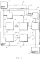
- Fig. 1 illustrates a traffic situation 1 with vehicles 2, 3, and 4 moving along a road 2 with three lanes 5, 6, and 7 and a branch-off lane 8.
- the vehicle 2 herein in the following also referred to as host vehicle, is equipped with sensor equipment 9 corresponding to the sensor means 9 in the appended claims, and further an ECU 10 (Electronic Control Unit - corresponding to the control means in the appended claims).
- the ECU 10 may be implemented by one central or by plural distributed hardware units such as signal processors, central processing units (CPU) onboard the host vehicle 2.
- Software or firmware is installed on the ECU 10 in order to implement one or more adaptive driving assistant systems (ADAS) to assist a driver in control of the host vehicle 2.
- ADAS adaptive driving assistant systems
- ADAS function implemented, such as a version of a predictive advanced cruise control (ACC) system or another cruise control function, the operation of which includes a prediction of the further evolution of the scenario shown in Fig. 1 in the future, including a prediction of the further behavior of host vehicle 2.
- ACC predictive advanced cruise control
- a prediction of the further evolution of the scenario shown in Fig. 1 in the future including a prediction of the further behavior of host vehicle 2.
- the following description of an embodiment is based on the ACC system for sake of clarity, but by no means limited thereto.
- Figs.2A to 2D showing an embodiment of the present invention are now discussed with reference to the traffic scenario in Fig. 1 .
- signals are shown with their respective signal values on the ordinate axis and the abscissa axis 17 showing the time.
- a decision signal as basis for the ACC system decision under consideration is generated by a first evaluation in the form of a computation that is based on one or more data items of sensor information and optionally an internal state of the system.
- the systems decision is then derived by, e.g. comparing the generated decision signal to a signal threshold.
- Fig. 2A depicts the decision signal 14, a signal threshold 15 and an activation signal 16 representing the decision made by the ACC system.
- the decision signal 14 can, for example, represent the difference in velocity to the preceding target vehicle 3 and the decision to brake is taken if the difference in velocity exceeds a certain threshold 15. If the decision signal 14 is high, the host vehicle 2 decelerates and does apply the brakes of the host vehicle.
- FIG. 2A shows the typical fluctuation due to unsteady and noisy input data from sensor means 9 to the ACC system.
- the decision signal 14 breaks down because the target vehicle 3 is lost by the sensor means 9 of the host vehicle 2 due to occlusion, for example.
- an unstabilized decision taken based on the decision signal 14 also fluctuates.
- the unstabilized decision resp. decision signal 14 in Fig. 2A leads to an activation signal 16 dropping to a low value in region 18 of Fig. 2A as well as in region 19 of Fig. 2A .
- the host vehicle 2 therefore stops braking even though the target vehicle 3 is still present but, for example, not perceived any longer in the traffic scenario 1 according to Fig. 1 .
- ACC systems may employ stabilizing the perception and therefore the decision signal 14. Rather than stabilizing the decision signal 14 and thus all parts of a processing chain of the ACC system usually comprising sensor means 9 together with all subsequent processing steps, the systems decision can be stabilized by stabilizing the activation signal 23 as shown in Fig. 2B .
- This form of stabilization has the advantage that it is independent of the processing steps forming part of the ACC system and the sensor means 9 and takes into account all possible problems leading to signal fluctuations in the processing chain from sensor means 9 onwards.
- Fig. 2B shows the effect of fluctuations of the decision signal 14 in decision stabilization.
- Figs. 2C and 2D show an advantageous embodiment of the invention.
- the basic idea of the present invention is to stabilize the system's decision and detect changes in the environment requiring the adaptation of the systems behaviour to cancel or to interrupt the stabilization of a decision. Thereby a quick adaptation of the ACC system to a new situation is achieved and the problem of a fluctuation and a high latency in the ACC system's decisions is overcome.
- the ACC system stabilizes the system's decision to employ an activation signal for braking the host vehicle 2 but additionally detects changes in the environment like a lane change according to trajectory 13 of the target vehicle 3, the system detects the lane-change of the target vehicle 3 in region 25 and thus is able to interrupt the stabilization of the activation signal 27 in Fig. 2C .
- This effect is shown in Fig. 2C , where a stabilized decision resp. activation signal 27 does not fluctuate in region 25 but quickly drops in region 26 to a low level.
- the ACC system according to an embodiment has no evidence in region 25 of Fig. 2C , to a scenario change because the target vehicle 3 disappeared from the perceived traffic scenario 1. Therefore, in region 25 of Fig.
- Fig. 2C shows as an example a decision interrupt signal 28 over time 17.
- a changed decision environment is perceived by means of a second evaluation and decided with a high degree of confidence.
- a stabilization interrupt signal 28 changes to a high level.
- the decision is abandoned, resulting in Fig. 2C to a drop of the activation signal 27 to a low level at the start of the period 26.
- the ACC system quickly reacts to the new scenario by abandoning the brake decision in the scenario according to Fig. 1 by setting the activation signal 27 to low level.
- the time 30 for deciding the changed environment for the decision is detected and decided before the decision signal 14 drops to a value below the signal threshold 15 at the beginning of period 26 in Fig. 2C .
- the second evaluation may also lead to generating a decision signal 41 and deciding an interrupt at any other time.
- the stabilisation interrupt signal 28 changes to the high level in Fig. 2D
- the stabilisation of the activation signal 16 is terminated and an activation decision means 36 is enabled to make a decision on an action based on the decision signal 14 and threshold 15 for the actual scenario anew.
- Fig. 3 illustrates functional components of the ECU 10 of the host vehicle 2 according to an embodiment of the invention.
- the functional components described and discussed below may be associated to a cruise control module implementing one or more ACC functionalities in the ECU 10 resp. control means 10.
- Sensor data 38 from the sensor means 9 is obtained by a first evaluation means 33 which operates to generate predictions by generating a decision signal 14 based on the sensor data 38.
- the decision signal 14 representing information related to a generated prediction is provided to an activation decision means 36 which is configured to determine whether the decision signal 14 exceeds a signal threshold 15.
- the signal threshold 15 is generated in a dynamic threshold generation means 37 based on sensor data 38 and/or a vehicle state 39 of the host vehicle 2.
- the activation decision means 36 decides the decision signal 14 to exceed the signal threshold 15, an activation signal 16 is generated.
- the activation signal 16 at a high level corresponds to an active control of the ACC system required for the host vehicle 2. This may be a brake signal in the present embodiment when confronted with the traffic scenario 1 depicted in Fig. 1 .
- the activation signal 16 is adapted to accordingly control one or more components of the host vehicle 2 related to control of specific functions of host vehicle 2, exemplarily illustrated by components adapted for braking control (BC), acceleration control (AC), and steering control (SC). These components are all included in the actuating means 32 of Fig. 3 .
- the sensor means 9 may comprise one or more radar transceivers, one or more cameras, one or more laser distance measurement devices, etc.
- the first evaluation means 33 may comprise a module or subsystem for generating physical predictions (PP) and/or a module or subsystem for generating context based predictions (CBP).
- the sensor data accepted from sensor means 9 is provided to an intermediate data processing which may comprise a component for providing direct data indicators (dI), and a component for providing indirect data indicators (iI).
- the direct indicators serve as a data basis for both the PP subsystem and CBP subsystem, while the indirect indicators serve as a data basis for the CBP subsystem only.
- Fig. 3 shows the functional components of the ECU 10 in the host vehicle 2.
- the functional components described and discussed below may be associated to a cruise control module implementing one or more ACC functionalities in the ECU 10.
- the decision signal 14 is generated in the evaluation means 33 based on the sensor data 38.
- the sensor data 38 undergoes transformation in a processing chain of the ACC system in order to generate a suitable signal to base a decision for generation of an activation signal 16 thereon.
- the activation signal 16 may be a brake signal in one embodiment. Nevertheless the activation signal 16 may represent any other signal generated based on a decision in the ACC system.
- a threshold generation means 37 a signal threshold 15 is generated and supplied to an activation decision means 36.
- the signal threshold 15 may either be predefined or may be calculated according to sensor data 38 or other sensory information or may be determined according to an internal state 39 of the host vehicle 2 resp.
- the decision signal 14 can be either a raw signal as delivered by a processing chain of an ACC system or a temporally filtered decision signal.
- the optional filtering is done in a filter means 34 being implemented as a low-pass filter or alternatively or additionally by a hysteresis on the decision signal 14 generated in the first evaluation means 33.
- control means 10 generates a decision interrupt signal 41 by detecting typical situations in the decision environment that require a change in the system behaviour.
- This decision interrupt signal 41 is computed in a second evaluation means 40 of the control means 10 for example based on sensor data 38 and/or the internal state 39 of the ACC system, but nevertheless not limited thereto.
- the decision signal 14 is compared to the signal threshold 15 in order to generate an activation signal 16 when the decision signal 14 exceeds the threshold 15.
- the activation signal 16 is then supplied to a stabilization means 42 being configured to stabilize the activation signal 16 and to provide a stabilized activation signal 27.
- the activation signal 16 representing the resulting ACC system decision may be stabilized in the stabilization means 42 using temporal filtering, e.g., by keeping the system decision and the activation signal 16 for a defined time in a defined state.
- This defined time can either be derived from a fixed constant time span or can be dynamically calculated in a dynamic timeout generation means 43 according to, e.g. sensor confidence 46, environmental information like the number of vehicles and/or host vehicle information like the current host vehicle velocity, sensor data 38 or the vehicle state 39.
- the optional dynamic timeout would be provided by the dynamic time out generation means 43 to the stabilization means 42.
- the stabilization interrupt signal 28 output by the stabilization interrupt decision means 45 is used to interrupt the stabilization.
- the stabilization interrupt signal 28 can, in one embodiment of the invention, be used, for example, for resetting a timeout in the stabilization means 42 generated by the a dynamic timeout generation means 43 for holding the activation signal 16 after a change in the activation signal 16 and thereby enable to switch the decision of the ACC system.
- a stabilized activation signal 27 representing a decision of the ACC system is output by the stabilization means 42 and provided to one or more actuating means 32 to generate an externally observable behaviour of the ACC system and thereby the host vehicle 2 based on a decision taken on sensor data 38.
- the second evaluation means 40 is configured to execute the second evaluation based on a classification algorithm applied on one or more parameters.
- the classification algorithms employed may be, as mere examples, algorithms such as the support-vector machines, the nearest-neighbor-classifiers or similar algorithms being suitable to determine if the ACC system in a specific situation of the scenario should by enabled to cancel a taken decision, e.g., a brake decision.
- a lane change of the target vehicle 3 on the lane change trajectory 13 can be detected as such a typical situation by a classifier and the stabilization algorithm like hysteresis or timeout stabilization of the respective activation signal 16, in the illustrative example a brake signal, is interrupted based on the decision interrupt signal 41.
- the second evaluation means 40 generates the decision interrupt signal 41 and supplies it to an interrupt decision means 45 of the control means 10.
- the decision interrupt means 45 compares the decision interrupt signal 41 with a decision threshold and, when the decision threshold is exceeded by the decision interrupt signal 41, the decision interrupt means 45 outputs a stabilization interrupt signal 28 to the stabilization means 42 for interrupting the stabilization of the activation signal 16 and therefore the stabilized activation signal 27. This allows the ACC system to quickly adapt the behavior to the new situation, which might result in reshaping the decision based on the sensor data 38 and its evaluation in the first evaluation means 33.
- the stabilization of the activation signal 27 is terminated when the host vehicle 2 and its ECU 10 reliably detects the lane change of the target vehicle 3 towards the exit lane 8 on the trajectory 13.
- the brake signal being applied in response to an anticipated change of the target vehicle 3 on a trajectory 12 from lane 6 to lane 5 following a predictive decision of the ACC system of the host vehicle 2 may therefore be subject to adaptation to the new situation in the traffic scenario 1.
- the second evaluation means 40 classification algorithms are applied on one or more parameters for deciding independent from the first evaluation on the traffic scenario 1.
- the parameters which could be used for effectively judging the scenario may be, for example, indicators based on the host vehicle 2 and its behaviour such as, for example, the host vehicle 2 itself starting a lane change as indicated by the blinker of the host vehicle 2, the position in the lane 5, 6, 7 or a typical lateral movement of the host vehicle 2.
- Another indicator relating to the host vehicle 2 and its vehicle state 39 may be the deactivation of the predictive ACC system by the driver of the host vehicle 2 by, e.g., using an off-switch or hitting a brake pedal of the host vehicle.
- environment based indicators comprise detected traffic rules indicated by a traffic sign 9 like "no overtaking allowed”, “speed-limit”, “exit lane starting” or information on the road like solid "no-overtaking lane markers”.
- Other vehicle based indicators may comprise the detection that a target vehicle 3, e.g., on the right lane 7, changes the lane to an irrelevant lane, i.e. to the right lane 7.
- the second evaluation means 40 evaluating and the interrupt decision means 45 deciding that the target vehicle 3 brakes to the speed of its predecessor vehicle 4 is also a suitable other vehicle indicator. Also the detection that the target vehicle 3, e.g. on the right lane 6, sets blinker to an irrelevant lane, i.e. the right blinker.
- the given examples of parameters or indicators for basing the second evaluation thereon are by no means intended to be exhaustive. Any other suitable indicator may be used alone or in combination with other indicators for generating the decision interrupt signal 41.
- a perceived environment of the host vehicle 2 is perceived to detect changes in the environment that require in change in the ACC system's reaction and therefore the activation signal 16 and stabilized activation signal 27.
- the activation signal 16 and stabilized activation signal 27 it is important to separate sensor problems such as vanishing vehicles, suddenly changing lane directions etc. from actual changes in the environment.
- the operation of the ECU 10 is related to an active control of host vehicle 2 by issuing for example brake signals, deceleration signals, steering signals, etc.
- Another indirect indicator may relate to relative velocities of the vehicles 2, 3, 4 to each other.
- vehicles 2, 3 and 4 travel with individual velocities and in directions indicated by the respective arrows attached to the vehicles 2, 3, 4 representations respectively, which are indicated in the Fig. 1 as absolute velocities relative to ground for ease of understanding.
- the host vehicle 2 has a higher absolute velocity than vehicle 4 with its lower velocity.
- vehicle 3 approaches vehicle 4 may be used by the ACC system in the first evaluation means 33 as one indication that target vehicle 3 may perform a lane change when further approaching vehicle 4 both traveling on lane 6.
- the lane change may lead on the trajectory 12 to lane 5, where the host vehicle 2 is approaching with an even higher velocity.
- an active driving assistance system is assumed.
- the decision of a potential lane change of vehicle 3 with highest probability of all analyzed potential behaviors of the target vehicle 3, on the basis of the context based analysis, is to be made.
- the activation decision means 36 may then decide to generate an active control signal in the form of the activation signal 16 to initiate a strong braking of the host vehicle 2 in order to allow vehicle 3 the lane change on trajectory 12 and to avoid a potentially dangerous situation.
- vehicle 3 in fact follows trajectory 13 rather than the predicted trajectory 12.
- vehicle 3 may take an exit lane 8 of the road section, and the exit has either not or not yet been detected by sensor means 9 due to a general limitation of the sensor means 9 regarding analysis of non-moving objects and/or due to data fuzziness, or the behavior related to the trajectory 13 has been assigned a low probability only in the context based analysis in the first evaluation means 33, for example due to a high absolute velocity of vehicle 3.
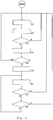
- step S1 The operation as illustrated in Fig. 4 starts in step S1 with evaluating sensor data 38 with a first evaluation and generation of a decision signal 14 based on the first evaluation.
- step S2 a signal threshold 15 is determined, either by calculating from sensor data 38 or other sensory information or by reading a predefined signal threshold 38 from a storage means.
- the decision signal 14 and the signal threshold 15 are compared in a step S3.
- the decision signal 14 is determined to exceed the threshold 15 the method proceeds to step S4. If the decision signal 14 does not exceed the threshold 15, it is judged that no situation requiring a defined control action, such as, e.g., issuing a brake command, has to be addressed by the ACC system and the method returns to step S1.
- step S4 the activation signal 16 comprises a brake signal in the host vehicle 2 in order to cope with the target vehicle 3 changing on the trajectory 12 from lane 6 to lane 5 in order to evade a collision with the vehicle 4 with low velocity in front of target vehicle 3.
- step S5 it is determined, if the activation signal 16 has been changed in the step S5, and if not the method returns to step S1. If indeed a brake signal resp. activation signal 16 is issued and accordingly the activation signal 16 changes, the method proceeds to step S6.
- step S6 the activation signal 15 is stabilized in order to cope with sensor data fluctuations and then the method proceeds to the step S7.
- step S7 the control means 10 generates a decision interrupt signal 41 by detecting typical situations in the decision environment that require a change in the ACC system behaviour.
- This decision interrupt signal 41 is computed in a second evaluation means 40 of the control means 10, for example based on sensor data 38 and/or the internal state 39 of the ACC system 39. But any of the suitable parameters might serve to generate the decision interrupt signal 41 by the second evaluation in step S7.
- step S8 the interrupt decision signal 41 is compared to a threshold in order to decide if a stabilization interrupt of the activation signal 16 is necessary. Any other kind of deciding can also be used instead or in addition to comparing the interrupt decision signal 41 with a threshold. If a stabilization interrupt of the activation signal 16 is decided to be necessary as a new situation has been detected, e.g. the target vehicle 3 is confirmed to change on trajectory 13 to the exit lane 8 in Fig. 1 , the stabilization of the activation signal 27 is terminated and the method returns to step S1 for new assessing of the situation based on the first evaluation.
- a stabilization interrupt of the activation signal 16 is decided not to be necessary, as e.g. a new situation cannot be detected with sufficient confidence, e.g. the target vehicle 3 changing on trajectory 13 to the exit lane 8 in Fig. 1 is not detected or not detected with sufficient probability, the stabilization of the activation signal 27 continues and the method therefore proceeds to step S9.
- step S9 it is determined if the stabilization of the stabilized activation signal 27 is to be terminated due to a preset or an adaptively determined stabilization time running out. If the decision in step 9 is yes, the method returns to step S1 for assessing the traffic scenario based on the first evaluation. If the stabilization time in step S9 is still determined to be running, the method proceeds to step S7 for continuing stabilizing the taken decision resp. outputting the stabilized activation signal 27 to the activation means 32.
- the method and the system as claimed are suitable to avoid confusion of other traffic participants, minimize disturbance of traffic flow, etc.
- the entire environment of the host vehicle 2 might have to be evaluated in this respect, including a rearward area.
- the control means 10 may adapt a strength, a limit and/or timelines for an active control of the host vehicle 2 by the activation signal 27 accordingly.
- control means 9 may operate to initiate a forwarding of information related to the intended and/or ongoing automated active control by the (stabilized) activation signal 16, 27 to other systems of the host-vehicle 2 and/or other vehicles 3, 4.
- an adaptive cruise control system not limited to detecting moving objects in front of the host vehicle and predicting a behavior thereof, but which may also be related to detecting and predicting moving objects in an area rearward of the host vehicle.
- an automatic cruise control may execute lane change maneuvers to give way to faster vehicles approaching from behind.
- the invention may be implemented with any other kind of driving assistant applicable to predictions exceeding cruise control, such as parking assistants, and assistant functionalities to be developed in the future also requiring consistent behaviour generation of decisions for active driving control of vehicles.
Landscapes
- Engineering & Computer Science (AREA)
- Transportation (AREA)
- Mechanical Engineering (AREA)
- Automation & Control Theory (AREA)
- Human Computer Interaction (AREA)
- Traffic Control Systems (AREA)
- Steering Control In Accordance With Driving Conditions (AREA)
- Control Of Driving Devices And Active Controlling Of Vehicle (AREA)
- Regulating Braking Force (AREA)
Claims (21)
- Verfahren für ein Fahrerunterstützungssystem für ein Fahrzeug (2), wobei das Fahrzeug wenigstens eine Sensoreinrichtung (9), wenigstens eine Betätigungseinrichtung (32) und eine Steuereinrichtung (10) aufweist, wobei das Verfahren die folgenden Schritte aufweist:- Erzeugen eines Entscheidungssignals (14) durch eine erste Auswertung von Sensordaten (38), die von der Sensoreinrichtung (9) erlangt wurden;- Erzeugen eines Aktivierungssignals (16) für die Betätigungseinrichtung (32), wenn das Entscheidungssignal (14) einen Signalschwellwert (15) übersteigt; und- Erzeugen eines Unterbrechungsentscheidungssignals (41) für das Betätigungssignal (16) basierend auf einer zweiten Auswertung;
gekennzeichnet durch- Stabilisieren des Aktivierungssignals (16) in einer zeitlichen Weise, um die Schwankung in dem Aktivierungssignal zu verhindern;- basierend auf dem Entscheidungsunterbrechungssignal (41) Entscheiden, ob die Stabilisierung des Aktivierungssignals (16) unterbrochen werden soll; und- Unterbrechen der Stabilisierung des Aktivierungssignals (16), wenn entschieden wird, das Aktivierungssignal (16) zu unterbrechen. - Verfahren nach Anspruch 1, dadurch gekennzeichnet, dass
das Entscheidungssignal (15) mit einem Tiefpassfilter (34) zeitlich gefiltert wird. - Verfahren nach einem der vorhergehenden Ansprüche, dadurch gekennzeichnet, dass das Aktivierungssignal (16) basierend auf dem Entscheidungssignal (14) erzeugt wird, wobei eine Hysterese berücksichtigt wird.
- Verfahren nach einem der vorhergehenden Ansprüche, dadurch gekennzeichnet, dass das Aktivierungssignal (16) eine vorgegebene Zeit lang aufrecht erhalten wird, wenn das Entscheidungssignal (14) auf einen Wert unter dem Signalschwellwert (15) zurückkehrt.
- Verfahren nach einem der vorhergehenden Ansprüche, dadurch gekennzeichnet, dass das Stabilisieren des Aktivierungssignals (16) in einer zeitlichen Weise das Stabilisieren des Aktivierungssignals (16) über eine vorgegebene Zeit aufweist.
- Verfahren nach einem der vorhergehenden Ansprüche, dadurch gekennzeichnet, dass die zweite Auswertung das Auswerten eines oder mehrerer Parameter aufweist, wobei die Parameter wenigstens eine Fahrzeuganzeige und/oder wenigstens eine Umgebungsanzeige und/oder wenigstens eine weitere Fahrzeuganzeige aufweisen, um das Unterbrechungsentscheidungssignal zu erzeugen.
- Fahrerunterstützungssystem mit Programmcodeeinrichtungen zum Ausführen der Verfahrensschritte nach einem der Ansprüche 1 bis 6, wenn das Programm auf einem Computer oder digitalen Signalprozessor ausgeführt wird.
- Fahrerunterstützungssystem zum Steuern eines Fahrzeugs, wobei das Fahrerunterstützungssystem aufweist:wenigstens eine Sensoreinrichtung (9), die konfiguriert ist, um Sensordaten (38) zu erlangen,wenigstens eine Betätigungseinrichtung (32), die konfiguriert ist, um eine Steuertätigkeit für das Fahrzeug (2) durchzuführen, undeine Steuereinrichtung (10), wobei die Steuereinrichtungen aufweisen: eine erste Auswertungseinrichtung (33), die konfiguriert ist, um ein Entscheidungssignal (14) aus den von der Sensoreinrichtung (9) erlangten Sensordaten zu erzeugen, eine Aktivierungsentscheidungseinrichtung (36), die konfiguriert ist, um ein Aktivierungssignal (16) für die Steuertätigkeit zu erzeugen, wenn das Entscheidungssignal (14) einen Signalschwellwert (15) übersteigt, und eine zweite Auswertungseinrichtung (40), die konfiguriert ist, um einUnterbrechungsentscheidungssignal (41) für das Aktivierungssignal (16) zu erzeugen, dadurch gekennzeichnet, dassdie Steuereinrichtung ferner aufweist:eine Stabilisierungseinrichtung (42), die konfiguriert ist, um das Aktivierungssignal (16) in einer zeitlichen Weise zu stabilisieren, um eine Schwankung in dem Aktivierungssignal zu verhindern;eine Unterbrechungsentscheidungseinrichtung (45), die konfiguriert ist, um basierend auf dem Entscheidungsunterbrechungssignal (41) zu entscheiden, ob die Stabilisierung des Aktivierungssignals (16) unterbrochen werden soll; und wobei die Aktivierungsentscheidungseinrichtung (36) konfiguriert ist, um das Aktivierungssignal (16) für die Steuertätigkeit zu erzeugen, wenn das Entscheidungssignal (14) einen Signalschwellwert (15) übersteigt, und die Stabilisierungseinrichtung (42) konfiguriert ist, um die Stabilisierung des Aktivierungssignals (16) zu unterbrechen, wenn entschieden wird, die Stabilisierung des Aktivierungssignals (16) zu unterbrechen.
- System nach Anspruch 8 oder Verfahren nach Anspruch 1, dadurch gekennzeichnet, dass
der Signalschwellwert (15) vorbestimmt ist. - System nach einem der Ansprüche 8 oder 9 oder Verfahren nach einem der Ansprüche 1 bis 6 und 9, dadurch gekennzeichnet, dass
der Signalschwellwert (15) basierend auf den Sensordaten (38) und/oder einem internen Zustand des Fahrzeugs (2) dynamisch bestimmt wird. - System nach einem der Ansprüche 8 bis 10, dadurch gekennzeichnet, dass die Steuereinrichtung (10) eine Filtereinrichtung (34) aufweist, die konfiguriert ist, um das Entscheidungssignal (14) zeitlich mit einem Tiefpassfilter zu filtern.
- System nach einem der Ansprüche 8 bis 11, dadurch gekennzeichnet, dass die Steuereinrichtung (10) konfiguriert ist, um das Aktivierungssignal (16) zu stabilisieren, wobei eine Hysterese berücksichtigt wird.
- System nach einem der Ansprüche 8 bis 12, dadurch gekennzeichnet, dass die Aktivierungseinrichtung (42) konfiguriert ist, um das stabilisierte Aktivierungssignal (16) eine vorgegebene Zeit lang aufrecht zu erhalten, wenn das Entscheidungssignal (14) auf einen Wert unter dem Signalschwellwert (15) zurückkehrt.
- System nach einem der Ansprüche 8 bis 13, dadurch gekennzeichnet, dass die Aktivierungseinrichtung (42) konfiguriert ist, um das Aktivierungssignal (16) eine vorgegebene Zeit lang in einer zeitlichen Weise zu stabilisieren.
- System nach einem der Ansprüche 8 bis 14 oder Verfahren nach einem der Ansprüche 1 bis 6, 9 und 10, dadurch gekennzeichnet, dass
das Entscheidungsunterbrechungssignal (41) ein Fahrbahnwechselsignal für ein weiteres Fahrzeugs (3) aufweist. - System nach Anspruch 15 oder Verfahren nach Anspruch 15, dadurch gekennzeichnet, dass
das Fahrbahnwechselsignal für das weitere Fahrzeug (3) ausgegeben wird, bevor das weitere Fahrzeug (3) eine Fahrspur (5, 6, 7) wechselt. - System nach einem der Ansprüche 8 bis 16 oder Verfahren nach einem der Ansprüche 1 bis 6, 9, 10, 15 und 16, dadurch gekennzeichnet, dass
das System oder das Verfahren in einem adaptiven Steuersystem für konstantes Fahren enthalten ist. - System nach einem der Ansprüche 8 bis 17 oder Verfahren nach einem der Ansprüche 1 bis 6, 9, 10 und 15 bis 17, dadurch gekennzeichnet, dass
das Aktivierungssignal (16) ein Bremssignal ist. - System nach einem der Ansprüche 8 bis 18, dadurch gekennzeichnet,
dass die zweite Auswertungseinrichtung (40) konfiguriert ist, um einen oder mehrere Parameter auszuwerten, wobei der/die Parameter wenigstens eine Fahrzeuganzeige und/oder wenigstens eine Umgebungsanzeige und/oder wenigstens eine weitere Fahrzeuganzeige aufweist/en, um das Unterbrechungsentscheidungssignal (41) zu erzeugen. - System nach einem der Ansprüche 8 bis 19 oder Verfahren nach einem der Ansprüche 1 bis 6, 9, 10 und 15 bis 18, dadurch gekennzeichnet, dass
die zweite Auswertung das Auswerten von Eingangsdaten, welche die Sensordaten (38) aufweisen, basierend auf einem Klassifizierungsalgorithmus, aufweist, wobei der Klassifizierungsalgorithmus einen Hilfsvektormaschinenalgorithums oder einen Nächste-Nachbar-Klassifzierungsalgorithmus aufweist. - System nach einem der Ansprüche 8 bis 20 oder Verfahren nach einem der Ansprüche 1 bis 6, 9, 10 und 15 bis 20, dadurch gekennzeichnet, dass
die erste Auswertung das Erzeugen des Entscheidungssignals (14) basierend auf kontextbasierter Vorhersage aufweist.
Priority Applications (3)
| Application Number | Priority Date | Filing Date | Title |
|---|---|---|---|
| EP13181312.3A EP2840007B1 (de) | 2013-08-22 | 2013-08-22 | Konsistente Verhaltenserzeugung eines erweiterten vorhersagbaren Fahrerhilfssystems |
| JP2014164266A JP6404634B2 (ja) | 2013-08-22 | 2014-08-12 | 予測的な先進運転支援システムの一貫性のある挙動生成 |
| US14/462,771 US9463806B2 (en) | 2013-08-22 | 2014-08-19 | Consistent behavior generation of a predictive advanced driver assistant system |
Applications Claiming Priority (1)
| Application Number | Priority Date | Filing Date | Title |
|---|---|---|---|
| EP13181312.3A EP2840007B1 (de) | 2013-08-22 | 2013-08-22 | Konsistente Verhaltenserzeugung eines erweiterten vorhersagbaren Fahrerhilfssystems |
Publications (2)
| Publication Number | Publication Date |
|---|---|
| EP2840007A1 EP2840007A1 (de) | 2015-02-25 |
| EP2840007B1 true EP2840007B1 (de) | 2018-04-04 |
Family
ID=49028948
Family Applications (1)
| Application Number | Title | Priority Date | Filing Date |
|---|---|---|---|
| EP13181312.3A Active EP2840007B1 (de) | 2013-08-22 | 2013-08-22 | Konsistente Verhaltenserzeugung eines erweiterten vorhersagbaren Fahrerhilfssystems |
Country Status (3)
| Country | Link |
|---|---|
| US (1) | US9463806B2 (de) |
| EP (1) | EP2840007B1 (de) |
| JP (1) | JP6404634B2 (de) |
Families Citing this family (26)
| Publication number | Priority date | Publication date | Assignee | Title |
|---|---|---|---|---|
| US9446766B2 (en) * | 2013-02-01 | 2016-09-20 | Hitachi Automotive Systems, Ltd. | Travel control device and travel control system |
| US9208691B2 (en) * | 2013-03-28 | 2015-12-08 | Caterpillar Inc. | Machine system having overtaking functionality |
| US10071748B2 (en) | 2015-09-17 | 2018-09-11 | Sony Corporation | System and method for providing driving assistance to safely overtake a vehicle |
| EP3150465B1 (de) * | 2015-10-01 | 2018-12-12 | Volvo Car Corporation | Verfahren und system zur anzeige eines potenziellen fahrspurwechsels eines fahrzeugs |
| DE102017212607A1 (de) | 2017-07-21 | 2019-01-24 | Ford Global Technologies, Llc | Verfahren und Vorrichtung zur umgebungsbasierten Adaption von Fahrerassistenzsystem-Funktionen |
| JP7116355B2 (ja) * | 2017-09-28 | 2022-08-10 | トヨタ自動車株式会社 | 運転支援装置 |
| US10336320B2 (en) * | 2017-11-22 | 2019-07-02 | Ford Global Technologies, Llc | Monitoring of communication for vehicle remote park-assist |
| US10665127B2 (en) | 2017-11-28 | 2020-05-26 | Toyota Motor Engineering & Manufacturing North America, Inc. | Systems and methods for sharing driver coaching data |
| US10793161B2 (en) | 2017-12-06 | 2020-10-06 | Toyota Motor Engineering & Manufacturing North America, Inc. | Systems and methods for selective driver coaching based on driver efficiency |
| US11048265B2 (en) | 2018-06-18 | 2021-06-29 | Zoox, Inc. | Occlusion aware planning |
| US10642275B2 (en) * | 2018-06-18 | 2020-05-05 | Zoox, Inc. | Occulsion aware planning and control |
| JP6689337B2 (ja) * | 2018-09-12 | 2020-04-28 | 三菱電機株式会社 | 自動運転制御装置および自動運転制御方法 |
| US11353577B2 (en) | 2018-09-28 | 2022-06-07 | Zoox, Inc. | Radar spatial estimation |
| DE102018219769A1 (de) * | 2018-11-19 | 2020-05-20 | Audi Ag | Verfahren zum Betreiben eines Aktuators eines Kraftfahrzeugs, Trainingseinrichtung, Kraftfahrzeug, System mit einem Kraftfahrzeug und einem tragbaren Gerät |
| US10919532B2 (en) * | 2018-12-04 | 2021-02-16 | GM Global Technology Operations LLC | Apparatus and method for longitudinal control in automatic lane change in an assisted driving vehicle |
| US11220255B2 (en) | 2019-01-30 | 2022-01-11 | Toyota Motor Engineering & Manufacturing North America, Inc. | Systems and methods for mitigating trailer instability due to pressure differentials |
| US11016492B2 (en) * | 2019-02-28 | 2021-05-25 | Zoox, Inc. | Determining occupancy of occluded regions |
| DE102019206047A1 (de) * | 2019-04-26 | 2020-10-29 | Robert Bosch Gmbh | Training trainierbarer Module mit Lern-Daten, deren Labels verrauscht sind |
| JP7309594B2 (ja) * | 2019-12-18 | 2023-07-18 | Kddi株式会社 | 合流支援情報配信装置、合流支援システム、合流支援情報配信方法及びコンピュータプログラム |
| CN114603549A (zh) * | 2020-12-08 | 2022-06-10 | 山东新松工业软件研究院股份有限公司 | 驱动器智能停车的控制方法及系统 |
| CN112714316B (zh) * | 2020-12-21 | 2023-01-31 | 太原智林信息技术股份有限公司 | 基于视频码流的规则标志检测和分类识别方法 |
| DE102021126820A1 (de) * | 2021-10-15 | 2023-04-20 | Bayerische Motoren Werke Aktiengesellschaft | Verfahren und Verarbeitungseinrichtung zum Steuern einer Fahrassistenzfunktion und Fahrassistenzsystem |
| US12114138B2 (en) | 2021-10-20 | 2024-10-08 | Ford Global Technologies, Llc | Multi-vehicle audio system |
| CN113859235B (zh) * | 2021-10-21 | 2022-04-08 | 名商科技有限公司 | 智能化自动巡航管理系统及方法 |
| TWI812344B (zh) * | 2022-07-13 | 2023-08-11 | 國立雲林科技大學 | 基於先進駕駛輔助系統中行車狀態的駕駛威脅分析控制系統及其方法 |
| DE102023107575A1 (de) | 2023-03-27 | 2024-10-02 | Valeo Schalter Und Sensoren Gmbh | Verfahren zum betreiben einer adaptiven geschwindigkeitsregelung |
Family Cites Families (34)
| Publication number | Priority date | Publication date | Assignee | Title |
|---|---|---|---|---|
| US5463384A (en) * | 1991-02-11 | 1995-10-31 | Auto-Sense, Ltd. | Collision avoidance system for vehicles |
| US7421321B2 (en) * | 1995-06-07 | 2008-09-02 | Automotive Technologies International, Inc. | System for obtaining vehicular information |
| US7783403B2 (en) * | 1994-05-23 | 2010-08-24 | Automotive Technologies International, Inc. | System and method for preventing vehicular accidents |
| US7313467B2 (en) * | 2000-09-08 | 2007-12-25 | Automotive Technologies International Inc. | System and method for in-vehicle communications |
| US7655894B2 (en) * | 1996-03-25 | 2010-02-02 | Donnelly Corporation | Vehicular image sensing system |
| US20120116632A1 (en) * | 1997-04-02 | 2012-05-10 | Bechtel Jon H | System for controlling vehicle equipment |
| US6171276B1 (en) * | 1997-08-06 | 2001-01-09 | Pharmacia & Upjohn Ab | Automated delivery device and method for its operation |
| DE10025678B4 (de) * | 2000-05-24 | 2006-10-19 | Daimlerchrysler Ag | Kamerabasiertes Precrash-Erkennungssystem |
| DE10118707A1 (de) * | 2001-04-12 | 2002-10-17 | Bosch Gmbh Robert | Verfahren zur Kollisionsverhinderung bei Kraftfahrzeugen |
| JP3775353B2 (ja) * | 2002-06-19 | 2006-05-17 | 日産自動車株式会社 | 先行車追従制御装置 |
| DE10258617B4 (de) * | 2002-09-20 | 2007-06-14 | Daimlerchrysler Ag | Verfahren und Vorrichtung zur Auslösung eines selbsttätigen Notbremsvorgangs eines Fahrzeug |
| JP3870911B2 (ja) * | 2003-02-10 | 2007-01-24 | 日産自動車株式会社 | 車線逸脱防止装置 |
| EP1495932B1 (de) * | 2003-07-07 | 2007-08-29 | Nissan Motor Company, Limited | Steuersystem für ein Fahrzeug zum Halten der Fahrspur |
| US7526103B2 (en) * | 2004-04-15 | 2009-04-28 | Donnelly Corporation | Imaging system for vehicle |
| DE102005011241A1 (de) * | 2005-03-11 | 2006-09-14 | Robert Bosch Gmbh | Verfahren und Vorrichtung zur Kollisionswarnung |
| JP4466571B2 (ja) * | 2005-05-12 | 2010-05-26 | 株式会社デンソー | ドライバ状態検出装置、車載警報装置、運転支援システム |
| DE102005028370A1 (de) * | 2005-06-20 | 2006-12-28 | Robert Bosch Gmbh | Verfahren zur Erkennung eines bevorstehenden Spurwechsels |
| EP1818233B1 (de) * | 2006-02-14 | 2011-09-07 | Ford Global Technologies, LLC | Verzögerungswarnvorrichtung und -verfahren für ein Kraftfahrzeug |
| DE102006018723A1 (de) * | 2006-04-20 | 2007-10-25 | Hans Edmund Hochrein | Fahrzeugaufprallwarner |
| DE102008003205A1 (de) * | 2008-01-04 | 2009-07-09 | Wabco Gmbh | Vorrichtung, Verfahren und Computerprogramm zur Kollisionsvermeidung oder zur Verminderung der Kollisionsschwere infolge einer Kollision für Fahrzeuge, insbesondere Nutzfahrzeuge |
| JP4602444B2 (ja) * | 2008-09-03 | 2010-12-22 | 株式会社日立製作所 | ドライバ運転技能支援装置及びドライバ運転技能支援方法 |
| CA2649731C (en) * | 2008-11-05 | 2015-07-21 | The George Washington University | An unobtrusive driver drowsiness detection method |
| US8244408B2 (en) | 2009-03-09 | 2012-08-14 | GM Global Technology Operations LLC | Method to assess risk associated with operating an autonomic vehicle control system |
| JP5402478B2 (ja) * | 2009-09-30 | 2014-01-29 | 株式会社アドヴィックス | 車両運動制御装置 |
| US20120022739A1 (en) * | 2010-07-20 | 2012-01-26 | Gm Global Technology Operations, Inc. | Robust vehicular lateral control with front and rear cameras |
| DE102010041147A1 (de) * | 2010-09-21 | 2012-03-22 | Continental Teves Ag & Co. Ohg | Verfahren und System zur Verringerung einer Reaktionstotzeit einer Fahrzeugsicherheitskontrolleinrichtung |
| JP5657997B2 (ja) * | 2010-10-29 | 2015-01-21 | アイシン精機株式会社 | 車両の横方向運動制御装置 |
| JP5547607B2 (ja) * | 2010-10-29 | 2014-07-16 | アイシン精機株式会社 | 車両の横方向運動制御装置 |
| WO2012077204A1 (ja) * | 2010-12-08 | 2012-06-14 | トヨタ自動車 株式会社 | 運転支援装置 |
| DE102011102927A1 (de) * | 2011-05-31 | 2012-12-06 | GM Global Technology Operations LLC (n. d. Gesetzen des Staates Delaware) | Verfahren zum Betreiben eines Fahrerassistenzsystems eines Kraftfahrzeugs und Fahrerassistenzsystem für ein Kraftfahrzeug |
| DE102011078776A1 (de) * | 2011-07-07 | 2013-01-10 | Robert Bosch Gmbh | Vorrichtung und Verfahren zum Betreiben eines Fahrzeugs |
| EP2562060B1 (de) | 2011-08-22 | 2014-10-01 | Honda Research Institute Europe GmbH | Verfahren und System zur Vorhersage des Bewegungsverhaltens eines Zielverkehrsobjekts |
| DE102013102087A1 (de) * | 2013-03-04 | 2014-09-04 | Conti Temic Microelectronic Gmbh | Verfahren zum Betrieb eines Fahrerassistenzsystems eines Fahrzeugs |
| EP2845779B1 (de) * | 2013-09-09 | 2018-08-01 | Honda Research Institute Europe GmbH | Fahrassistenztechnik zur aktiven Fahrzeugsteuerung |
-
2013
- 2013-08-22 EP EP13181312.3A patent/EP2840007B1/de active Active
-
2014
- 2014-08-12 JP JP2014164266A patent/JP6404634B2/ja active Active
- 2014-08-19 US US14/462,771 patent/US9463806B2/en active Active
Non-Patent Citations (1)
| Title |
|---|
| None * |
Also Published As
| Publication number | Publication date |
|---|---|
| EP2840007A1 (de) | 2015-02-25 |
| JP2015061776A (ja) | 2015-04-02 |
| JP6404634B2 (ja) | 2018-10-10 |
| US9463806B2 (en) | 2016-10-11 |
| US20150057907A1 (en) | 2015-02-26 |
Similar Documents
| Publication | Publication Date | Title |
|---|---|---|
| EP2840007B1 (de) | Konsistente Verhaltenserzeugung eines erweiterten vorhersagbaren Fahrerhilfssystems | |
| US9656667B2 (en) | Method for minimizing automatic braking intrusion based on collision confidence | |
| JP6822752B2 (ja) | アクティブ車両制御のための運転支援技術 | |
| CN107719363B (zh) | 用于沿着路径引导机动车辆的控制系统和控制方法 | |
| CN110733501B (zh) | 用于自动避免碰撞的方法 | |
| EP3476676B1 (de) | System und verfahren zur durchführung einer autonomen notbremsung | |
| US9566981B2 (en) | Method and system for post-collision manoeuvre planning and vehicle equipped with such system | |
| US9104965B2 (en) | Vehicle with computing means for monitoring and predicting traffic participant objects | |
| CN106043297B (zh) | 在反向操作期间基于前轮跑偏的避撞 | |
| US8949018B2 (en) | Driving assistance device and driving assistance method | |
| CN111942352B (zh) | 考虑转向路径的自适应aeb系统及其控制方法 | |
| US11713041B2 (en) | Control system and control method for driving a motor vehicle | |
| CN109572690B (zh) | 车辆控制装置 | |
| WO2019034514A1 (en) | METHOD AND SYSTEM FOR AVOIDING THE COLLISION OF A VEHICLE | |
| CN113853640B (zh) | 电子控制装置 | |
| CN108146434B (zh) | 用于驾驶机动车辆的控制系统和控制方法 | |
| CN106458173B (zh) | 用于运行车辆的方法和设备 | |
| CN108944949B (zh) | 操作车辆的拥堵辅助系统的方法 | |
| KR101957922B1 (ko) | 차량 간 충돌 방지 방법 및 장치 | |
| US12024165B2 (en) | Evaluation apparatus for evaluating a trajectory hypothesis for a vehicle | |
| WO2024135201A1 (ja) | 走行支援装置、及び走行支援装置の走行支援方法 | |
| US20240182022A1 (en) | Preventive safety device and vehicle |
Legal Events
| Date | Code | Title | Description |
|---|---|---|---|
| PUAI | Public reference made under article 153(3) epc to a published international application that has entered the european phase |
Free format text: ORIGINAL CODE: 0009012 |
|
| 17P | Request for examination filed |
Effective date: 20140730 |
|
| AK | Designated contracting states |
Kind code of ref document: A1 Designated state(s): AL AT BE BG CH CY CZ DE DK EE ES FI FR GB GR HR HU IE IS IT LI LT LU LV MC MK MT NL NO PL PT RO RS SE SI SK SM TR |
|
| AX | Request for extension of the european patent |
Extension state: BA ME |
|
| GRAP | Despatch of communication of intention to grant a patent |
Free format text: ORIGINAL CODE: EPIDOSNIGR1 |
|
| STAA | Information on the status of an ep patent application or granted ep patent |
Free format text: STATUS: GRANT OF PATENT IS INTENDED |
|
| RIC1 | Information provided on ipc code assigned before grant |
Ipc: B60W 30/095 20120101ALI20170929BHEP Ipc: B60W 50/00 20060101AFI20170929BHEP Ipc: B60T 7/12 20060101ALN20170929BHEP Ipc: B60W 50/06 20060101ALI20170929BHEP |
|
| INTG | Intention to grant announced |
Effective date: 20171024 |
|
| GRAS | Grant fee paid |
Free format text: ORIGINAL CODE: EPIDOSNIGR3 |
|
| GRAA | (expected) grant |
Free format text: ORIGINAL CODE: 0009210 |
|
| STAA | Information on the status of an ep patent application or granted ep patent |
Free format text: STATUS: THE PATENT HAS BEEN GRANTED |
|
| AK | Designated contracting states |
Kind code of ref document: B1 Designated state(s): AL AT BE BG CH CY CZ DE DK EE ES FI FR GB GR HR HU IE IS IT LI LT LU LV MC MK MT NL NO PL PT RO RS SE SI SK SM TR |
|
| REG | Reference to a national code |
Ref country code: GB Ref legal event code: FG4D |
|
| REG | Reference to a national code |
Ref country code: CH Ref legal event code: EP |
|
| REG | Reference to a national code |
Ref country code: AT Ref legal event code: REF Ref document number: 985274 Country of ref document: AT Kind code of ref document: T Effective date: 20180415 |
|
| REG | Reference to a national code |
Ref country code: IE Ref legal event code: FG4D |
|
| REG | Reference to a national code |
Ref country code: DE Ref legal event code: R096 Ref document number: 602013035313 Country of ref document: DE |
|
| REG | Reference to a national code |
Ref country code: NL Ref legal event code: MP Effective date: 20180404 |
|
| REG | Reference to a national code |
Ref country code: FR Ref legal event code: PLFP Year of fee payment: 6 |
|
| REG | Reference to a national code |
Ref country code: LT Ref legal event code: MG4D |
|
| PG25 | Lapsed in a contracting state [announced via postgrant information from national office to epo] |
Ref country code: NL Free format text: LAPSE BECAUSE OF FAILURE TO SUBMIT A TRANSLATION OF THE DESCRIPTION OR TO PAY THE FEE WITHIN THE PRESCRIBED TIME-LIMIT Effective date: 20180404 |
|
| PG25 | Lapsed in a contracting state [announced via postgrant information from national office to epo] |
Ref country code: LT Free format text: LAPSE BECAUSE OF FAILURE TO SUBMIT A TRANSLATION OF THE DESCRIPTION OR TO PAY THE FEE WITHIN THE PRESCRIBED TIME-LIMIT Effective date: 20180404 Ref country code: PL Free format text: LAPSE BECAUSE OF FAILURE TO SUBMIT A TRANSLATION OF THE DESCRIPTION OR TO PAY THE FEE WITHIN THE PRESCRIBED TIME-LIMIT Effective date: 20180404 Ref country code: FI Free format text: LAPSE BECAUSE OF FAILURE TO SUBMIT A TRANSLATION OF THE DESCRIPTION OR TO PAY THE FEE WITHIN THE PRESCRIBED TIME-LIMIT Effective date: 20180404 Ref country code: BG Free format text: LAPSE BECAUSE OF FAILURE TO SUBMIT A TRANSLATION OF THE DESCRIPTION OR TO PAY THE FEE WITHIN THE PRESCRIBED TIME-LIMIT Effective date: 20180704 Ref country code: NO Free format text: LAPSE BECAUSE OF FAILURE TO SUBMIT A TRANSLATION OF THE DESCRIPTION OR TO PAY THE FEE WITHIN THE PRESCRIBED TIME-LIMIT Effective date: 20180704 Ref country code: SE Free format text: LAPSE BECAUSE OF FAILURE TO SUBMIT A TRANSLATION OF THE DESCRIPTION OR TO PAY THE FEE WITHIN THE PRESCRIBED TIME-LIMIT Effective date: 20180404 Ref country code: AL Free format text: LAPSE BECAUSE OF FAILURE TO SUBMIT A TRANSLATION OF THE DESCRIPTION OR TO PAY THE FEE WITHIN THE PRESCRIBED TIME-LIMIT Effective date: 20180404 Ref country code: ES Free format text: LAPSE BECAUSE OF FAILURE TO SUBMIT A TRANSLATION OF THE DESCRIPTION OR TO PAY THE FEE WITHIN THE PRESCRIBED TIME-LIMIT Effective date: 20180404 |
|
| PG25 | Lapsed in a contracting state [announced via postgrant information from national office to epo] |
Ref country code: GR Free format text: LAPSE BECAUSE OF FAILURE TO SUBMIT A TRANSLATION OF THE DESCRIPTION OR TO PAY THE FEE WITHIN THE PRESCRIBED TIME-LIMIT Effective date: 20180705 Ref country code: HR Free format text: LAPSE BECAUSE OF FAILURE TO SUBMIT A TRANSLATION OF THE DESCRIPTION OR TO PAY THE FEE WITHIN THE PRESCRIBED TIME-LIMIT Effective date: 20180404 Ref country code: LV Free format text: LAPSE BECAUSE OF FAILURE TO SUBMIT A TRANSLATION OF THE DESCRIPTION OR TO PAY THE FEE WITHIN THE PRESCRIBED TIME-LIMIT Effective date: 20180404 Ref country code: RS Free format text: LAPSE BECAUSE OF FAILURE TO SUBMIT A TRANSLATION OF THE DESCRIPTION OR TO PAY THE FEE WITHIN THE PRESCRIBED TIME-LIMIT Effective date: 20180404 |
|
| REG | Reference to a national code |
Ref country code: AT Ref legal event code: MK05 Ref document number: 985274 Country of ref document: AT Kind code of ref document: T Effective date: 20180404 |
|
| PG25 | Lapsed in a contracting state [announced via postgrant information from national office to epo] |
Ref country code: PT Free format text: LAPSE BECAUSE OF FAILURE TO SUBMIT A TRANSLATION OF THE DESCRIPTION OR TO PAY THE FEE WITHIN THE PRESCRIBED TIME-LIMIT Effective date: 20180806 |
|
| REG | Reference to a national code |
Ref country code: DE Ref legal event code: R097 Ref document number: 602013035313 Country of ref document: DE |
|
| PG25 | Lapsed in a contracting state [announced via postgrant information from national office to epo] |
Ref country code: DK Free format text: LAPSE BECAUSE OF FAILURE TO SUBMIT A TRANSLATION OF THE DESCRIPTION OR TO PAY THE FEE WITHIN THE PRESCRIBED TIME-LIMIT Effective date: 20180404 Ref country code: EE Free format text: LAPSE BECAUSE OF FAILURE TO SUBMIT A TRANSLATION OF THE DESCRIPTION OR TO PAY THE FEE WITHIN THE PRESCRIBED TIME-LIMIT Effective date: 20180404 Ref country code: CZ Free format text: LAPSE BECAUSE OF FAILURE TO SUBMIT A TRANSLATION OF THE DESCRIPTION OR TO PAY THE FEE WITHIN THE PRESCRIBED TIME-LIMIT Effective date: 20180404 Ref country code: AT Free format text: LAPSE BECAUSE OF FAILURE TO SUBMIT A TRANSLATION OF THE DESCRIPTION OR TO PAY THE FEE WITHIN THE PRESCRIBED TIME-LIMIT Effective date: 20180404 Ref country code: SK Free format text: LAPSE BECAUSE OF FAILURE TO SUBMIT A TRANSLATION OF THE DESCRIPTION OR TO PAY THE FEE WITHIN THE PRESCRIBED TIME-LIMIT Effective date: 20180404 Ref country code: RO Free format text: LAPSE BECAUSE OF FAILURE TO SUBMIT A TRANSLATION OF THE DESCRIPTION OR TO PAY THE FEE WITHIN THE PRESCRIBED TIME-LIMIT Effective date: 20180404 |
|
| PLBE | No opposition filed within time limit |
Free format text: ORIGINAL CODE: 0009261 |
|
| STAA | Information on the status of an ep patent application or granted ep patent |
Free format text: STATUS: NO OPPOSITION FILED WITHIN TIME LIMIT |
|
| PG25 | Lapsed in a contracting state [announced via postgrant information from national office to epo] |
Ref country code: IT Free format text: LAPSE BECAUSE OF FAILURE TO SUBMIT A TRANSLATION OF THE DESCRIPTION OR TO PAY THE FEE WITHIN THE PRESCRIBED TIME-LIMIT Effective date: 20180404 Ref country code: SM Free format text: LAPSE BECAUSE OF FAILURE TO SUBMIT A TRANSLATION OF THE DESCRIPTION OR TO PAY THE FEE WITHIN THE PRESCRIBED TIME-LIMIT Effective date: 20180404 |
|
| 26N | No opposition filed |
Effective date: 20190107 |
|
| PG25 | Lapsed in a contracting state [announced via postgrant information from national office to epo] |
Ref country code: MC Free format text: LAPSE BECAUSE OF FAILURE TO SUBMIT A TRANSLATION OF THE DESCRIPTION OR TO PAY THE FEE WITHIN THE PRESCRIBED TIME-LIMIT Effective date: 20180404 |
|
| REG | Reference to a national code |
Ref country code: CH Ref legal event code: PL |
|
| PG25 | Lapsed in a contracting state [announced via postgrant information from national office to epo] |
Ref country code: LU Free format text: LAPSE BECAUSE OF NON-PAYMENT OF DUE FEES Effective date: 20180822 Ref country code: LI Free format text: LAPSE BECAUSE OF NON-PAYMENT OF DUE FEES Effective date: 20180831 Ref country code: CH Free format text: LAPSE BECAUSE OF NON-PAYMENT OF DUE FEES Effective date: 20180831 |
|
| REG | Reference to a national code |
Ref country code: BE Ref legal event code: MM Effective date: 20180831 |
|
| PG25 | Lapsed in a contracting state [announced via postgrant information from national office to epo] |
Ref country code: SI Free format text: LAPSE BECAUSE OF FAILURE TO SUBMIT A TRANSLATION OF THE DESCRIPTION OR TO PAY THE FEE WITHIN THE PRESCRIBED TIME-LIMIT Effective date: 20180404 |
|
| PG25 | Lapsed in a contracting state [announced via postgrant information from national office to epo] |
Ref country code: BE Free format text: LAPSE BECAUSE OF NON-PAYMENT OF DUE FEES Effective date: 20180831 |
|
| PG25 | Lapsed in a contracting state [announced via postgrant information from national office to epo] |
Ref country code: MT Free format text: LAPSE BECAUSE OF NON-PAYMENT OF DUE FEES Effective date: 20180822 |
|
| PG25 | Lapsed in a contracting state [announced via postgrant information from national office to epo] |
Ref country code: TR Free format text: LAPSE BECAUSE OF FAILURE TO SUBMIT A TRANSLATION OF THE DESCRIPTION OR TO PAY THE FEE WITHIN THE PRESCRIBED TIME-LIMIT Effective date: 20180404 |
|
| PG25 | Lapsed in a contracting state [announced via postgrant information from national office to epo] |
Ref country code: HU Free format text: LAPSE BECAUSE OF FAILURE TO SUBMIT A TRANSLATION OF THE DESCRIPTION OR TO PAY THE FEE WITHIN THE PRESCRIBED TIME-LIMIT; INVALID AB INITIO Effective date: 20130822 |
|
| PG25 | Lapsed in a contracting state [announced via postgrant information from national office to epo] |
Ref country code: IE Free format text: LAPSE BECAUSE OF NON-PAYMENT OF DUE FEES Effective date: 20180822 Ref country code: MK Free format text: LAPSE BECAUSE OF NON-PAYMENT OF DUE FEES Effective date: 20180404 Ref country code: CY Free format text: LAPSE BECAUSE OF FAILURE TO SUBMIT A TRANSLATION OF THE DESCRIPTION OR TO PAY THE FEE WITHIN THE PRESCRIBED TIME-LIMIT Effective date: 20180404 |
|
| REG | Reference to a national code |
Ref country code: DE Ref legal event code: R084 Ref document number: 602013035313 Country of ref document: DE |
|
| PG25 | Lapsed in a contracting state [announced via postgrant information from national office to epo] |
Ref country code: IS Free format text: LAPSE BECAUSE OF FAILURE TO SUBMIT A TRANSLATION OF THE DESCRIPTION OR TO PAY THE FEE WITHIN THE PRESCRIBED TIME-LIMIT Effective date: 20180804 |
|
| REG | Reference to a national code |
Ref country code: GB Ref legal event code: 746 Effective date: 20200812 |
|
| PGFP | Annual fee paid to national office [announced via postgrant information from national office to epo] |
Ref country code: DE Payment date: 20240826 Year of fee payment: 12 |
|
| PGFP | Annual fee paid to national office [announced via postgrant information from national office to epo] |
Ref country code: GB Payment date: 20240822 Year of fee payment: 12 |
|
| PGFP | Annual fee paid to national office [announced via postgrant information from national office to epo] |
Ref country code: FR Payment date: 20240821 Year of fee payment: 12 |