EP2839909A1 - Machine tool - Google Patents
Machine tool Download PDFInfo
- Publication number
- EP2839909A1 EP2839909A1 EP20130769582 EP13769582A EP2839909A1 EP 2839909 A1 EP2839909 A1 EP 2839909A1 EP 20130769582 EP20130769582 EP 20130769582 EP 13769582 A EP13769582 A EP 13769582A EP 2839909 A1 EP2839909 A1 EP 2839909A1
- Authority
- EP
- European Patent Office
- Prior art keywords
- tools
- axis
- feed axis
- feed
- machine tool
- Prior art date
- Legal status (The legal status is an assumption and is not a legal conclusion. Google has not performed a legal analysis and makes no representation as to the accuracy of the status listed.)
- Granted
Links
Images



Classifications
-
- B—PERFORMING OPERATIONS; TRANSPORTING
- B23—MACHINE TOOLS; METAL-WORKING NOT OTHERWISE PROVIDED FOR
- B23B—TURNING; BORING
- B23B29/00—Holders for non-rotary cutting tools; Boring bars or boring heads; Accessories for tool holders
- B23B29/24—Tool holders for a plurality of cutting tools, e.g. turrets
-
- B—PERFORMING OPERATIONS; TRANSPORTING
- B23—MACHINE TOOLS; METAL-WORKING NOT OTHERWISE PROVIDED FOR
- B23B—TURNING; BORING
- B23B29/00—Holders for non-rotary cutting tools; Boring bars or boring heads; Accessories for tool holders
- B23B29/24—Tool holders for a plurality of cutting tools, e.g. turrets
- B23B29/26—Tool holders in fixed position
-
- Y—GENERAL TAGGING OF NEW TECHNOLOGICAL DEVELOPMENTS; GENERAL TAGGING OF CROSS-SECTIONAL TECHNOLOGIES SPANNING OVER SEVERAL SECTIONS OF THE IPC; TECHNICAL SUBJECTS COVERED BY FORMER USPC CROSS-REFERENCE ART COLLECTIONS [XRACs] AND DIGESTS
- Y10—TECHNICAL SUBJECTS COVERED BY FORMER USPC
- Y10T—TECHNICAL SUBJECTS COVERED BY FORMER US CLASSIFICATION
- Y10T29/00—Metal working
- Y10T29/51—Plural diverse manufacturing apparatus including means for metal shaping or assembling
- Y10T29/5104—Type of machine
- Y10T29/5109—Lathe
-
- Y—GENERAL TAGGING OF NEW TECHNOLOGICAL DEVELOPMENTS; GENERAL TAGGING OF CROSS-SECTIONAL TECHNOLOGIES SPANNING OVER SEVERAL SECTIONS OF THE IPC; TECHNICAL SUBJECTS COVERED BY FORMER USPC CROSS-REFERENCE ART COLLECTIONS [XRACs] AND DIGESTS
- Y10—TECHNICAL SUBJECTS COVERED BY FORMER USPC
- Y10T—TECHNICAL SUBJECTS COVERED BY FORMER US CLASSIFICATION
- Y10T29/00—Metal working
- Y10T29/51—Plural diverse manufacturing apparatus including means for metal shaping or assembling
- Y10T29/5168—Multiple-tool holder
-
- Y—GENERAL TAGGING OF NEW TECHNOLOGICAL DEVELOPMENTS; GENERAL TAGGING OF CROSS-SECTIONAL TECHNOLOGIES SPANNING OVER SEVERAL SECTIONS OF THE IPC; TECHNICAL SUBJECTS COVERED BY FORMER USPC CROSS-REFERENCE ART COLLECTIONS [XRACs] AND DIGESTS
- Y10—TECHNICAL SUBJECTS COVERED BY FORMER USPC
- Y10T—TECHNICAL SUBJECTS COVERED BY FORMER US CLASSIFICATION
- Y10T29/00—Metal working
- Y10T29/51—Plural diverse manufacturing apparatus including means for metal shaping or assembling
- Y10T29/5168—Multiple-tool holder
- Y10T29/517—Laterally movable stock holder
-
- Y—GENERAL TAGGING OF NEW TECHNOLOGICAL DEVELOPMENTS; GENERAL TAGGING OF CROSS-SECTIONAL TECHNOLOGIES SPANNING OVER SEVERAL SECTIONS OF THE IPC; TECHNICAL SUBJECTS COVERED BY FORMER USPC CROSS-REFERENCE ART COLLECTIONS [XRACs] AND DIGESTS
- Y10—TECHNICAL SUBJECTS COVERED BY FORMER USPC
- Y10T—TECHNICAL SUBJECTS COVERED BY FORMER US CLASSIFICATION
- Y10T82/00—Turning
- Y10T82/16—Severing or cut-off
- Y10T82/16426—Infeed means
- Y10T82/16591—Power driven eccentric
- Y10T82/16622—Plural tools
-
- Y—GENERAL TAGGING OF NEW TECHNOLOGICAL DEVELOPMENTS; GENERAL TAGGING OF CROSS-SECTIONAL TECHNOLOGIES SPANNING OVER SEVERAL SECTIONS OF THE IPC; TECHNICAL SUBJECTS COVERED BY FORMER USPC CROSS-REFERENCE ART COLLECTIONS [XRACs] AND DIGESTS
- Y10—TECHNICAL SUBJECTS COVERED BY FORMER USPC
- Y10T—TECHNICAL SUBJECTS COVERED BY FORMER US CLASSIFICATION
- Y10T82/00—Turning
- Y10T82/25—Lathe
- Y10T82/2531—Carriage feed
- Y10T82/2541—Slide rest
- Y10T82/2543—Multiple tool support
-
- Y—GENERAL TAGGING OF NEW TECHNOLOGICAL DEVELOPMENTS; GENERAL TAGGING OF CROSS-SECTIONAL TECHNOLOGIES SPANNING OVER SEVERAL SECTIONS OF THE IPC; TECHNICAL SUBJECTS COVERED BY FORMER USPC CROSS-REFERENCE ART COLLECTIONS [XRACs] AND DIGESTS
- Y10—TECHNICAL SUBJECTS COVERED BY FORMER USPC
- Y10T—TECHNICAL SUBJECTS COVERED BY FORMER US CLASSIFICATION
- Y10T82/00—Turning
- Y10T82/25—Lathe
- Y10T82/2585—Tool rest
- Y10T82/2587—Turret type holder [e.g., multiple tools, etc.]
Definitions
- the present invention relates to a machine tool having a plurality of tools arranged in a combteeth manner.
- NC automatic lathe that includes feed screws along two mutually orthogonal axis directions on a plane orthogonal to an z axis, which is along a center line of a spindle, and that moves a tool post on an orthogonal X-Y coordinate system inclined against an orthogonal A-B coordinate system consisting of the axial directions of the feed screws to machine a workpiece (see Patent Literature 1, for example).
- a plurality of tools are arranged along a Y axis direction of the X-Y coordinate system and move in an X axis direction of the X-Y coordinate system to cut into the workpiece and perform machining.
- Patent Literature 2 discloses a method for adjusting a blade edge position of respective cutting tools provided on a comb-toothed tool post of a machine tool, such as an NC lathe, against a material to be machined on the basis of machining data. According to this method, when the NC lathe machines a bar, the comb-toothed tool post, on which cutting tools used for machining operation have been mounted, is moved so that a blade edge of a particular cutting tool whose blade edge position is to be adjusted comes into contact with a lateral desired point of the bar held at an actual machining position.
- the lateral desired point is approximately 90 degrees away from a vertex of the bar along a circumferential direction of the bar, the vertex being a point where the blade edge of respective cutting tools comes into contact with in machining operation.
- a Y coordinate value (absolute value) of a center, or rotational axis, of the bar is determined. Then, the blade edge of the particular cutting tool is moved to the Y coordinate value of the rotational axis of the bar for coming into contact with the vertex of the bar to perform cutting operation. This enables highly accurate machining.
- the above-described blade edge position adjustment is difficult to execute, however, against a bar having an outer diameter larger than an outer diameter Ra of a bar W1 that abuts an adjacent cutting tool, because the adjacent cutting tool interferes with the execution of the blade edge position adjustment.
- blade edges of respective tools 220 are staggered in a cut-in direction of the tools 220, which is orthogonal to an arrangement direction of the tools 220, in a stepwise fashion.
- the blade edge position adjustment can be executed against a bar W2 having an outer diameter Rb that is larger than a distance between two adjacent tools.
- the above-described machine tool has a problem that, because the blade edges of the respective tools 220 are staggered in the cut-in direction in a stepwise fashion, extra stroke lengths d1, d2, d3, and d4 corresponding to the amount of the staggering exist for the tools 220 when the blade edge position adjustment is executed for switching between the tools 220, or when the respective tools 220 cut into a workpiece W3, as shown in Figure 11 .
- tools T1, T2, T3, and T4 need to additionally move the extra stroke lengths d1, d2, d3, and d4, respectively, in the cut-in direction in comparison with a tool T0.
- the tools T1, T2, T3, and T4 need to move the extra stroke lengths d1, d2, d3, and d4, respectively, for machining operation, and also need to move back the same extra stroke lengths for switching between the tools T0, T1, T2, T3, and T4. This amounts to wasted time in non-cutting operation to extend machining time.
- the feed screws need to be adapted for moving the tool post for the extra stroke length of d4, which is the maximum staggering amount of the tools 220, in addition to the stroke length of the tool T0 in the cut-in direction.
- the resulting total stroke length is unnecessarily long for tools whose staggering amount is less than d4. Due to the elongation of the feed screws, the machine tool becomes larger and the machining time is extended, for example.
- a technical problem to be solved by the present invention, or an object of the present invention is to provide a machine tool that is capable of executing the blade edge position adjustment of a plurality of tools attached thereto against a bar having a larger diameter and that is also capable of reducing wasted time in non-cutting operation.
- a machine tool includes movement means, which has a first feed axis and a second feed axis that mutually intersect, and a plurality of tools, which are movable as a unit with the movement means. Respective blade edges of the plurality of tools are staggered in a stepwise fashion. The plurality of tools are arranged such that blade edges thereof are aligned with a straight line along a selection axis for selecting between the tools.
- one of the first feed axis and the second feed axis is selected as the selection axis, and the tools are inclined as a unit so that the blade edges thereof are aligned with the one of the first feed axis or the second feed axis.
- the first feed axis and the second feed axis are respectively set in a horizontal direction and a vertical direction that are orthogonal to each other.
- the plurality of tools are arranged in the vertical direction.
- a blade edge of an upper tool of any two adjacent tools of the plurality of tools projects with respect to a blade edge of a lower tool of the two adjacent tools for only a certain length with which cutting chips generated in machining operation with the upper tool do not fall on the lower tool.
- the other of the first feed axis and the second feed axis is inclined along a direction of the inclination of the tools.
- each tool can be directly moved to a tool standby position and wasted time in non-cutting operation can thus be reduced.
- the tools can be switched therebetween regardless of the staggering amount of respective blade edges to machine a workpiece.
- the blade edge position adjustment can be executed against a bar having an outer diameter larger than a distance between any two adjacent tools.
- the tools can be switched therebetween easily by moving the tools along the first feed axis or the second feed axis.
- Each tool can machine a workpiece without moving an extra stroke length in accordance with the staggering amount of the blade edge thereof, and the first feed axis or the second feed axis can be made compact.
- the machine tool because the stroke lengths in the horizontal direction and the vertical direction do not need to be made longer, the machine tool can be made compact in the horizontal direction and the vertical direction.
- the machine tool because the stroke length in the horizontal direction does not need to be made longer, the machine tool can be made compact in the horizontal direction.
- each tool can be selected by driving only one of the feed axes selected as the selection axes, a load on the machine tool can be reduced.
- the machine tool 100 is a machine tool such as an NC automatic lathe and includes a plurality of tools 120 such as cutting tools supported on a tool post 112, a front spindle 130, a back spindle 140, a back tool post 150, and a turret 160.
- the machine tool 100 is capable of machining a workpiece by giving and receiving the workpiece between the front spindle 130 and the back spindle 140.
- the tool post 112 is movably supported via a feed mechanism 110A on a first feed axis A and a feed mechanism 110B on a second feed axis B, the first feed axis A and the second feed axis B being mutually orthogonal.
- the feed mechanisms 110A and 110B constitute movement means 110 of the tool post 112.
- the first feed axis A and the second feed axis B are orthogonal to an axis direction Z1 of the front spindle 130 shown in Figure 1 .
- the feed mechanism 110A on the first feed axis A includes a first slide stand 110A-1 that is slidably supported on a slide rail 110A-2 along the first feed axis A and that is screwed with a first feed screw 111 A along the first feed axis A.
- the first feed screw 111 A is rotationally driven by a first motor 113A. Due to the driving force of the first motor 113A, the first slide stand 110A-1 moves along the first feed axis A.
- the feed mechanism 110B on the second feed axis B includes a second slide stand 110B-1 that is slidably supported on a slide rail 110B-2 along the second feed axis B and that is screwed with a second feed screw 111 B along the second feed axis B.
- the second feed screw 111 B is rotationally driven by a second motor 113B. Due to the driving force of the second motor 113B, the second slide stand 110B-1 moves along the second feed axis B.
- the tool post 112 is mounted on the second slide stand 110B-1 and moves along the first feed axis A via the rotation of the first feed screw 111 A and along the second feed axis B via the rotation of the second feed screw 111 B.
- the tools 120 are mounted on the tool post 112 as a unit.
- the movement means 110 can move the tool post 112 in any direction with the combined action of the first feed screw 111A and the second feed screw 111 B.
- the machine tool 100 can machine a round bar-shaped workpiece W held by the front spindle 130 shown in Figures 1 and 2 while switching between the tools 120 by moving the tools 120 in any direction via the movement means 110.
- the tools 120 are arranged in parallel to each other along a Y1 axis direction that is inclined with respect to the first feed axis A and the second feed axis B.
- the tools 120 are arranged so that the blade edges thereof are staggered in a stepwise fashion in an X1 axis direction perpendicular to the Y1 axis direction.
- the blade edges of the respective tools 120 are proportionally staggered and are positioned on a straight line L.
- the tools 120 are inclined as a unit so that the straight line L is aligned with the first feed axis B.
- an X1-Y1 coordinate system consisting of the X1 axis direction and the Y1 axis direction is rotated for a predetermined angle with respect to an A-B coordinate system consisting of the first feed axis A and the second feed axis B.
- the blade edge position adjustment is executed, as shown in Figure 5 , by firstly contacting a blade edge of a particular tool 120 with a top of the workpiece W in the Y1 axis direction and then, as with the conventional art, determining a Y1 coordinate value (absolute value) of a center, or rotational axis, of the workpiece W by using a Y1 coordinate value of the contacting position and a premeasured radius of the workpiece W.
- the blade edges of the respective tools 120 are positioned along and aligned with the second feed axis B, the blade edges are staggered in the X1 axis direction in a stepwise fashion.
- the blade edge position adjustment can be executed against the workpiece W having an outer diameter larger than a distance between two adjacent tools 120.
- the blade edge of the particular tool 120 is then moved to the Y1 coordinate value (Y0) of the rotational axis of the workpiece W and is subsequently moved in the X1 axis direction to cut into and machine the workpiece W. Because the blade edges of the respective tools 120 are aligned with the second feed axis B, the tools 120 can be switched therebetween by moving the tool post 112 along the second feed axis B regardless of the staggering of the blade edges in the X1 axis direction, as shown in Figure 7 .
- a particular tool 120 that has been used in machining operation is moved from the surface of the workpiece W to an escape position, or a tool standby position, which is small distance d away from the surface of the workpiece W in the X1 axis direction, or the cut-in direction of the tool 120.
- next machining operation can be started by simply moving the tool post 112 along the second feed axis B to position another tool 120 that will be used in next machining operation to the standby position, regardless of the staggering of the blade edge, and then moving the another tool 120 for the distance d, which is a minimum moving distance common to all the tools 120, without considering the staggering amount of the blade edge. Also, because the stroke length needed for starting machining operation is common to all the tools 120, a processing stroke does not need to be made longer in accordance with the staggering amount of the blade edges in the X1 axis direction.
- the respective tools 120 can be directly moved to the tool standby position to reduce wasted time in non-cutting operation.
- the strokes of the first feed screw 111 A and the second feed screw 111 B can be determined in accordance with the rotation (inclination) angle of the X1-Y1 coordinate system with respect to the A-B coordinate system without depending on the staggering amount of the blade edges of the respective tools 120.
- the strokes of the first feed screw 111 A and the second feed screw 111 B do not need to be made longer for the length corresponding to the staggering amount of the blade edges, and the first feed screw 111 A and the second feed screw 111 B can be made compact.
- the tools 120 are arranged in the vertical direction, the stroke length in the horizontal direction does not need to be made longer and the machine tool 100 can thus be made compact in the horizontal direction.
- the stroke lengths of the first feed screw 111 A and the second feed screw 111 B do not need to be made longer, the machine tool 100 can be made compact in the horizontal and vertical directions.
- the second feed axis B is selected as the selection axis and the blade edges of the respective tools 120 are aligned with the second feed axis B
- the tools 120 are switched therebetween by moving the tool post 112 along the first feed axis A.
- the wording that "the blade edges of the plurality of tools are aligned with a straight line along the selection axis of the tools” includes a situation in which a blade edge of an upper tool 120 of any two adjacent tools of the plurality of tools 120 projects with respect to a blade edge of a lower tool 120 of the two adjacent tools for only a certain length with which cutting chips generated in machining operation with the upper tool 120 do not fall on the lower tool 120, as shown in Figure 8 .
- the straight line L passing through the blade edges of the plurality of tools 120 is not required to coincide with the second feed axis B and may be simply along the second feed axis B, as shown in Figure 8 .
- the straight line L may be used as the selection axis.
- the first feed axis A and the second feed axis B are orthogonal to each other and the tools 120 (the tool post 112) is moved in the X1 axis direction with the combined action of the first feed screw 111 A and the second feed screw 111 B
- the second feed screw 111 B may be provided along the X1 axis direction so that the second feed axis B is set in the X1 axis direction, as shown in Figure 9 .
- the tool post 112 can be moved along the first feed axis A by driving only the first feed screw 111A and can be moved along the X1 axis direction by driving only the second feed screw 111 B. This enables easy and low-load movement of the tool post 112.
Landscapes
- Engineering & Computer Science (AREA)
- Mechanical Engineering (AREA)
- Cutting Tools, Boring Holders, And Turrets (AREA)
- Turning (AREA)
Abstract
Description
- The present invention relates to a machine tool having a plurality of tools arranged in a combteeth manner.
- There is a known NC automatic lathe that includes feed screws along two mutually orthogonal axis directions on a plane orthogonal to an z axis, which is along a center line of a spindle, and that moves a tool post on an orthogonal X-Y coordinate system inclined against an orthogonal A-B coordinate system consisting of the axial directions of the feed screws to machine a workpiece (see
Patent Literature 1, for example). In this case, a plurality of tools are arranged along a Y axis direction of the X-Y coordinate system and move in an X axis direction of the X-Y coordinate system to cut into the workpiece and perform machining. - Also,
Patent Literature 2 discloses a method for adjusting a blade edge position of respective cutting tools provided on a comb-toothed tool post of a machine tool, such as an NC lathe, against a material to be machined on the basis of machining data. According to this method, when the NC lathe machines a bar, the comb-toothed tool post, on which cutting tools used for machining operation have been mounted, is moved so that a blade edge of a particular cutting tool whose blade edge position is to be adjusted comes into contact with a lateral desired point of the bar held at an actual machining position. The lateral desired point is approximately 90 degrees away from a vertex of the bar along a circumferential direction of the bar, the vertex being a point where the blade edge of respective cutting tools comes into contact with in machining operation. On the basis of a Y coordinate value of the lateral desired position and a premeasured radius of the bar, a Y coordinate value (absolute value) of a center, or rotational axis, of the bar is determined. Then, the blade edge of the particular cutting tool is moved to the Y coordinate value of the rotational axis of the bar for coming into contact with the vertex of the bar to perform cutting operation. This enables highly accurate machining. - As shown in
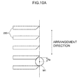
Figure 10A , the above-described blade edge position adjustment is difficult to execute, however, against a bar having an outer diameter larger than an outer diameter Ra of a bar W1 that abuts an adjacent cutting tool, because the adjacent cutting tool interferes with the execution of the blade edge position adjustment. Thus, as shown inFigure 10B , in a machine tool disclosed inPatent Literature 2, blade edges ofrespective tools 220 are staggered in a cut-in direction of thetools 220, which is orthogonal to an arrangement direction of thetools 220, in a stepwise fashion. Thus, the blade edge position adjustment can be executed against a bar W2 having an outer diameter Rb that is larger than a distance between two adjacent tools. -
- [Patent Literature 1]
Japanese Patent Laid-Open No.H7-308803 Figures 1 to 3 ) - [Patent Literature 2]
Japanese Patent Laid-Open No.2001-300802 Figures 1 to 6 ) - The above-described machine tool, however, has a problem that, because the blade edges of the
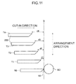
respective tools 220 are staggered in the cut-in direction in a stepwise fashion, extra stroke lengths d1, d2, d3, and d4 corresponding to the amount of the staggering exist for thetools 220 when the blade edge position adjustment is executed for switching between thetools 220, or when therespective tools 220 cut into a workpiece W3, as shown inFigure 11 . - For example, when the blade edge of the
respective tools 220 moves to a position of a Y coordinate value (Y0) of the rotational axis of the bar, tools T1, T2, T3, and T4 need to additionally move the extra stroke lengths d1, d2, d3, and d4, respectively, in the cut-in direction in comparison with a tool T0. In other words, the tools T1, T2, T3, and T4 need to move the extra stroke lengths d1, d2, d3, and d4, respectively, for machining operation, and also need to move back the same extra stroke lengths for switching between the tools T0, T1, T2, T3, and T4. This amounts to wasted time in non-cutting operation to extend machining time. - Also, when the blade edges of the
respective tools 220 are staggered in the cut-in direction in a stepwise fashion, the feed screws need to be adapted for moving the tool post for the extra stroke length of d4, which is the maximum staggering amount of thetools 220, in addition to the stroke length of the tool T0 in the cut-in direction. The resulting total stroke length, however, is unnecessarily long for tools whose staggering amount is less than d4. Due to the elongation of the feed screws, the machine tool becomes larger and the machining time is extended, for example. - Thus, a technical problem to be solved by the present invention, or an object of the present invention, is to provide a machine tool that is capable of executing the blade edge position adjustment of a plurality of tools attached thereto against a bar having a larger diameter and that is also capable of reducing wasted time in non-cutting operation.
- According to a first aspect of the present invention, a machine tool includes movement means, which has a first feed axis and a second feed axis that mutually intersect, and a plurality of tools, which are movable as a unit with the movement means. Respective blade edges of the plurality of tools are staggered in a stepwise fashion. The plurality of tools are arranged such that blade edges thereof are aligned with a straight line along a selection axis for selecting between the tools.
- According to a second aspect of the present invention, one of the first feed axis and the second feed axis is selected as the selection axis, and the tools are inclined as a unit so that the blade edges thereof are aligned with the one of the first feed axis or the second feed axis.
- According to a third aspect of the present invention, the first feed axis and the second feed axis are respectively set in a horizontal direction and a vertical direction that are orthogonal to each other.
- According to a fourth aspect of the present invention, the plurality of tools are arranged in the vertical direction.
- According to a fifth aspect of the present invention, a blade edge of an upper tool of any two adjacent tools of the plurality of tools projects with respect to a blade edge of a lower tool of the two adjacent tools for only a certain length with which cutting chips generated in machining operation with the upper tool do not fall on the lower tool.
- According to a sixth aspect of the present invention, with respect to the one of the first feed axis and the second feed axis that is selected as the selection axis, the other of the first feed axis and the second feed axis is inclined along a direction of the inclination of the tools.
- In the machine tool according to the first aspect of the present invention, because the blade edges of the respective tools are aligned with a straight line along the selection axis for selecting between the tools, each tool can be directly moved to a tool standby position and wasted time in non-cutting operation can thus be reduced. By moving the tools in the selection axis, the tools can be switched therebetween regardless of the staggering amount of respective blade edges to machine a workpiece. As with the known art, because the blade edges of the respective tools are staggered in the cut-in direction in a stepwise fashion, the blade edge position adjustment can be executed against a bar having an outer diameter larger than a distance between any two adjacent tools.
- In the machine tool according to the second aspect of the present invention, the tools can be switched therebetween easily by moving the tools along the first feed axis or the second feed axis. Each tool can machine a workpiece without moving an extra stroke length in accordance with the staggering amount of the blade edge thereof, and the first feed axis or the second feed axis can be made compact.
- In the machine tool according to the third aspect of the present invention, because the stroke lengths in the horizontal direction and the vertical direction do not need to be made longer, the machine tool can be made compact in the horizontal direction and the vertical direction.
- In the machine tool according to the fourth aspect of the present invention, because the stroke length in the horizontal direction does not need to be made longer, the machine tool can be made compact in the horizontal direction.
- In the machine tool according to the fifth aspect of the present invention, because cutting chips generated in machining operation do not fall on the lower tool, adhesion of the cutting chips to the tools can be prevented.
- In the machine tool according to the sixth aspect of the present invention, because each tool can be selected by driving only one of the feed axes selected as the selection axes, a load on the machine tool can be reduced.
-
- [
Figure 1] Figure 1 is a perspective view of a machine tool in accordance with an embodiment of the present invention. - [
Figure 2] Figure 2 is an internal front view of the machine tool in accordance with the embodiment of the present invention as seen from an interior to a front spindle side. - [
Figure 3] Figure 3 is a main part schematic front view of the machine tool in accordance with the embodiment of the present invention. - [
Figure 4] Figure 4 is a conceptual diagram describing an inclined state of a plurality of tools with respect to a second feed shaft. - [
Figure 5] Figure 5 is a conceptual diagram describing one step of a center level adjustment method. - [
Figure 6] Figure 6 is a conceptual diagram describing a state in which a tool cuts into a workpiece. - [
Figure 7] Figure 7 is a conceptual diagram describing a state in which tools are switched therebeteen. - [
Figure 8] Figure 8 is a conceptual diagram describing another inclined state of the plurality of tools with respect to the second feed axis. - [
Figure 9] Figure 9 is a main part schematic front view of a machine tool in accordance with another embodiment of the present invention. - [
Figure 10A] Figure 10A is a conceptual diagram illustrating a (first) relative positional relationship between a plurality of tools and a workpiece in a conventional machine tool. - [
Figure 10B] Figure 10B is a conceptual diagram illustrating a (second) relative positional relationship between a plurality of tools and a workpiece in a conventional machine tool. - [
Figure 11] Figure 11 is a conceptual diagram illustrating a (third) relative positional relationship between a plurality of tools and a workpiece in a conventional machine tool. - A
machine tool 100 in accordance with one embodiment of the present invention will now be described. As shown inFigures 1 and2 , themachine tool 100 is a machine tool such as an NC automatic lathe and includes a plurality oftools 120 such as cutting tools supported on atool post 112, afront spindle 130, aback spindle 140, aback tool post 150, and aturret 160. Themachine tool 100 is capable of machining a workpiece by giving and receiving the workpiece between thefront spindle 130 and theback spindle 140. - The
tool post 112 is movably supported via afeed mechanism 110A on a first feed axis A and afeed mechanism 110B on a second feed axis B, the first feed axis A and the second feed axis B being mutually orthogonal. Thefeed mechanisms tool post 112. The first feed axis A and the second feed axis B are orthogonal to an axis direction Z1 of thefront spindle 130 shown inFigure 1 . - As shown in
Figures 1 to 3 , thefeed mechanism 110A on the first feed axis A includes a first slide stand 110A-1 that is slidably supported on aslide rail 110A-2 along the first feed axis A and that is screwed with afirst feed screw 111 A along the first feed axis A. Thefirst feed screw 111 A is rotationally driven by afirst motor 113A. Due to the driving force of thefirst motor 113A, the first slide stand 110A-1 moves along the first feed axis A. Thefeed mechanism 110B on the second feed axis B includes a second slide stand 110B-1 that is slidably supported on aslide rail 110B-2 along the second feed axis B and that is screwed with asecond feed screw 111 B along the second feed axis B. Thesecond feed screw 111 B is rotationally driven by asecond motor 113B. Due to the driving force of thesecond motor 113B, the second slide stand 110B-1 moves along the second feed axis B. Thetool post 112 is mounted on the second slide stand 110B-1 and moves along the first feed axis A via the rotation of thefirst feed screw 111 A and along the second feed axis B via the rotation of thesecond feed screw 111 B. - The
tools 120 are mounted on thetool post 112 as a unit. The movement means 110 can move thetool post 112 in any direction with the combined action of thefirst feed screw 111A and thesecond feed screw 111 B. Themachine tool 100 can machine a round bar-shaped workpiece W held by thefront spindle 130 shown inFigures 1 and2 while switching between thetools 120 by moving thetools 120 in any direction via the movement means 110. - The
tools 120 are arranged in parallel to each other along a Y1 axis direction that is inclined with respect to the first feed axis A and the second feed axis B. As shown inFigure 4 with imaginary lines illustrating the Y1 axis direction as a horizontal direction, thetools 120 are arranged so that the blade edges thereof are staggered in a stepwise fashion in an X1 axis direction perpendicular to the Y1 axis direction. The blade edges of therespective tools 120 are proportionally staggered and are positioned on a straight line L. As shown inFigure 4 with solid lines, thetools 120 are inclined as a unit so that the straight line L is aligned with the first feed axis B. - Thus, an X1-Y1 coordinate system consisting of the X1 axis direction and the Y1 axis direction is rotated for a predetermined angle with respect to an A-B coordinate system consisting of the first feed axis A and the second feed axis B. With this configuration, each of the blade edges comes into contact with the workpiece W at a top of the workpiece W in the X1 axis direction in machining operation, and the X1 axis direction becomes a cut-in direction of the
tools 120. - Because each of the blade edges comes into contact with the workpiece W at a top of the workpiece W in the X1 axis direction in machining operation, the blade edge position adjustment is executed, as shown in
Figure 5 , by firstly contacting a blade edge of aparticular tool 120 with a top of the workpiece W in the Y1 axis direction and then, as with the conventional art, determining a Y1 coordinate value (absolute value) of a center, or rotational axis, of the workpiece W by using a Y1 coordinate value of the contacting position and a premeasured radius of the workpiece W. Even though the blade edges of therespective tools 120 are positioned along and aligned with the second feed axis B, the blade edges are staggered in the X1 axis direction in a stepwise fashion. Thus, the blade edge position adjustment can be executed against the workpiece W having an outer diameter larger than a distance between twoadjacent tools 120. - As shown in
Figure 6 , the blade edge of theparticular tool 120 is then moved to the Y1 coordinate value (Y0) of the rotational axis of the workpiece W and is subsequently moved in the X1 axis direction to cut into and machine the workpiece W. Because the blade edges of therespective tools 120 are aligned with the second feed axis B, thetools 120 can be switched therebetween by moving thetool post 112 along the second feed axis B regardless of the staggering of the blade edges in the X1 axis direction, as shown inFigure 7 . - For example, as shown in
Figure 7 , in order to switch between thetools 120, aparticular tool 120 that has been used in machining operation is moved from the surface of the workpiece W to an escape position, or a tool standby position, which is small distance d away from the surface of the workpiece W in the X1 axis direction, or the cut-in direction of thetool 120. Because the blade edges of therespective tools 120 are aligned with a straight line that is along the second feed axis B and that is passing through the tool standby position, next machining operation can be started by simply moving thetool post 112 along the second feed axis B to position anothertool 120 that will be used in next machining operation to the standby position, regardless of the staggering of the blade edge, and then moving the anothertool 120 for the distance d, which is a minimum moving distance common to all thetools 120, without considering the staggering amount of the blade edge. Also, because the stroke length needed for starting machining operation is common to all thetools 120, a processing stroke does not need to be made longer in accordance with the staggering amount of the blade edges in the X1 axis direction. - Thus, because the blade edges of the plurality of
tools 120 are aligned with a straight line along the selection axis for selecting between thetools 120, such as the second feed axis B, therespective tools 120 can be directly moved to the tool standby position to reduce wasted time in non-cutting operation. In addition, by selecting the second feed axis B as the selection axis and inclining thetools 120 as a unit so that the blade edges of therespective tools 120 are aligned with the second feed axis B, the strokes of thefirst feed screw 111 A and thesecond feed screw 111 B can be determined in accordance with the rotation (inclination) angle of the X1-Y1 coordinate system with respect to the A-B coordinate system without depending on the staggering amount of the blade edges of therespective tools 120. Thus, the strokes of thefirst feed screw 111 A and thesecond feed screw 111 B do not need to be made longer for the length corresponding to the staggering amount of the blade edges, and thefirst feed screw 111 A and thesecond feed screw 111 B can be made compact. Particularly, because thetools 120 are arranged in the vertical direction, the stroke length in the horizontal direction does not need to be made longer and themachine tool 100 can thus be made compact in the horizontal direction. Furthermore, in the present embodiment, because the stroke lengths of thefirst feed screw 111 A and thesecond feed screw 111 B do not need to be made longer, themachine tool 100 can be made compact in the horizontal and vertical directions. - Although in the above embodiment the second feed axis B is selected as the selection axis and the blade edges of the
respective tools 120 are aligned with the second feed axis B, it is also possible to select the first feed axis A as the selection axis and to align the blade edges with the first feed axis A. In this case, thetools 120 are switched therebetween by moving thetool post 112 along the first feed axis A. - In the present embodiment, the wording that "the blade edges of the plurality of tools are aligned with a straight line along the selection axis of the tools" includes a situation in which a blade edge of an
upper tool 120 of any two adjacent tools of the plurality oftools 120 projects with respect to a blade edge of alower tool 120 of the two adjacent tools for only a certain length with which cutting chips generated in machining operation with theupper tool 120 do not fall on thelower tool 120, as shown inFigure 8 . - In other words, as long as the projection of the
upper tool 120 with respect thelower tool 120 is restricted to a certain length with which cutting chips generated in machining operation with theupper tool 120 do not fall on thelower tool 120, the straight line L passing through the blade edges of the plurality oftools 120 is not required to coincide with the second feed axis B and may be simply along the second feed axis B, as shown inFigure 8 . With this arrangement of thetools 120, cutting chips generated in machining operation with theupper tool 120 do not fall on thelower tool 120. Thus, adhesion of the cutting chips to thetools 120 can be prevented. The straight line L may be used as the selection axis. - Although in the above embodiment the first feed axis A and the second feed axis B are orthogonal to each other and the tools 120 (the tool post 112) is moved in the X1 axis direction with the combined action of the
first feed screw 111 A and thesecond feed screw 111 B, thesecond feed screw 111 B may be provided along the X1 axis direction so that the second feed axis B is set in the X1 axis direction, as shown inFigure 9 . - In this case, the
tool post 112 can be moved along the first feed axis A by driving only thefirst feed screw 111A and can be moved along the X1 axis direction by driving only thesecond feed screw 111 B. This enables easy and low-load movement of thetool post 112. -
- 100
- Machine tool
- 110
- Movement means
- 110A
- Feed mechanism in a direction of A
- 110A-1
- First slide stand
- 110A-2
- Slide rail
- 110B
- Feed mechanism in a direction of B
- 110B-1
- Second slide stand
- 110B-2
- Slide rail
- 111A
- First feed screw
- 111B
- Second feed screw
- 112
- Tool post
- 120, 220
- Tool
- 130
- Front spindle
- 140
- Back spindle
- 150
- Back tool post
- 160
- Turret
- d1, d2, d3, d4
- Extra stroke length
- A
- First feed axis
- B
- Second feed axis
- X
- Cut-in direction of the tools
- Y
- Arrangement direction of the tools
- W, W1, W2, W3
- Workpiece
Claims (6)
- A machine tool including: movement means having a first feed axis and a second feed axis that mutually intersect; and a plurality of tools movable as a unit with the movement means,
respective blade edges of the plurality of tools being staggered in a stepwise fashion, characterized in that
the plurality of tools are arranged such that blade edges thereof are aligned with a straight line along a selection axis of the tools. - The machine tool according to claim 1, characterized in that
one of the first feed axis and the second feed axis is selected as the selection axis of the tools, and the tools are inclined as a unit so that the blade edges thereof are aligned with the one of the first feed axis or the second feed axis. - The machine tool according to claim 2, characterized in that the first feed axis and the second feed axis are respectively set in a horizontal direction and a vertical direction that are orthogonal to each other.
- The machine tool according to claim 3, characterized in that
the plurality of tools are arranged in the vertical direction. - The machine tool according to claim 4, characterized in that
a blade edge of an upper tool of any two adjacent tools of the plurality of tools projects with respect to a blade edge of a lower tool of the two adjacent tools for only a certain length with which cutting chips generated in machining operation with the upper tool do not fall on the lower tool. - The machine tool according to claim 2, characterized in that, with respect to one of the first feed axis and the second feed axis that is selected as the selection axis, the other of the first feed axis and the second feed axis is inclined along a direction of the inclination of the tools.
Applications Claiming Priority (2)
| Application Number | Priority Date | Filing Date | Title |
|---|---|---|---|
| JP2012069984 | 2012-03-26 | ||
| PCT/JP2013/058069 WO2013146525A1 (en) | 2012-03-26 | 2013-03-21 | Machine tool |
Publications (3)
| Publication Number | Publication Date |
|---|---|
| EP2839909A1 true EP2839909A1 (en) | 2015-02-25 |
| EP2839909A4 EP2839909A4 (en) | 2016-04-20 |
| EP2839909B1 EP2839909B1 (en) | 2022-01-26 |
Family
ID=49259781
Family Applications (1)
| Application Number | Title | Priority Date | Filing Date |
|---|---|---|---|
| EP13769582.1A Active EP2839909B1 (en) | 2012-03-26 | 2013-03-21 | Machine tool |
Country Status (8)
| Country | Link |
|---|---|
| US (1) | US10252345B2 (en) |
| EP (1) | EP2839909B1 (en) |
| JP (1) | JP6025220B2 (en) |
| KR (1) | KR101925309B1 (en) |
| CN (1) | CN104136159B (en) |
| ES (1) | ES2908099T3 (en) |
| TW (1) | TWI555606B (en) |
| WO (1) | WO2013146525A1 (en) |
Cited By (1)
| Publication number | Priority date | Publication date | Assignee | Title |
|---|---|---|---|---|
| EP3417995B1 (en) | 2017-06-21 | 2024-02-21 | Gildemeister Italiana S.r.l. | Machine tool, in particular multi-spindle turning machine |
Families Citing this family (5)
| Publication number | Priority date | Publication date | Assignee | Title |
|---|---|---|---|---|
| WO2016170845A1 (en) * | 2015-04-20 | 2016-10-27 | 村田機械株式会社 | Machine tool and cutting method |
| CN108555602A (en) * | 2018-06-04 | 2018-09-21 | 津上精密机床(浙江)有限公司 | A kind of high-power complex milling machine tool |
| CN108620959B (en) * | 2018-06-04 | 2024-02-06 | 津上精密机床(浙江)有限公司 | Automatic machining lathe for double-sided tool bit |
| CN111596609B (en) * | 2020-05-12 | 2021-08-24 | 珠海格力智能装备有限公司 | Control method and device for automatically adjusting machine tool level |
| CN112045144A (en) * | 2020-08-26 | 2020-12-08 | 温州大学 | A precise cutting and dividing mechanism for the main drive of a multi-station cold heading machine |
Family Cites Families (24)
| Publication number | Priority date | Publication date | Assignee | Title |
|---|---|---|---|---|
| US1821743A (en) * | 1928-03-16 | 1931-09-01 | Dreyhaupt Rudolf | Method and device for turning out the rings of roller bearings and similar grooved rings |
| JP3114773B2 (en) * | 1993-02-27 | 2000-12-04 | スター精密株式会社 | Automatic lathe |
| JP3355213B2 (en) * | 1993-02-27 | 2002-12-09 | スター精密株式会社 | Automatic lathe |
| JP3349586B2 (en) | 1994-05-13 | 2002-11-25 | シチズン時計株式会社 | NC automatic lathe |
| JP4403211B2 (en) * | 1999-07-09 | 2010-01-27 | 野村Vtc株式会社 | Positioning jig for the supporting unit of the spindle moving type automatic lathe |
| JP4480223B2 (en) * | 2000-04-24 | 2010-06-16 | シチズンホールディングス株式会社 | Comb tooth tool post and machine tool |
| JP2002018605A (en) * | 2000-06-30 | 2002-01-22 | Ngk Spark Plug Co Ltd | Part-Time Job |
| TW496804B (en) * | 2000-09-22 | 2002-08-01 | Citizen Watch Co Ltd | Automatically operated lathe |
| TW478990B (en) * | 2000-09-22 | 2002-03-11 | Citizen Watch Co Ltd | Numerically controlled lathe and method for controlling the same |
| JP4619620B2 (en) * | 2000-09-22 | 2011-01-26 | シチズンホールディングス株式会社 | Automatic lathe |
| JP3640618B2 (en) * | 2001-05-16 | 2005-04-20 | シチズン時計株式会社 | Numerically controlled lathe having comb-type counter tool post, workpiece machining method using this numerically controlled lathe, and program thereof |
| JP2004058227A (en) * | 2002-07-30 | 2004-02-26 | Citizen Watch Co Ltd | Tool selection method and control device in numerically controlled lathe |
| EP1648656B1 (en) * | 2003-07-31 | 2007-08-15 | Microswiss Technologie AG | Tool support for lathes |
| WO2008013313A1 (en) * | 2006-07-27 | 2008-01-31 | Citizen Holdings Co., Ltd. | Automatic lathe having a plurality of tool rests |
| EP2058071B1 (en) * | 2006-08-04 | 2012-04-11 | Citizen Holdings Co., Ltd. | Tool post |
| JPWO2009060579A1 (en) * | 2007-11-09 | 2011-03-17 | シチズンマシナリー株式会社 | Machine Tools |
| US20100268371A1 (en) * | 2007-11-09 | 2010-10-21 | Citizen Machinery Co., Ltd. | Machining tool |
| CN201214153Y (en) * | 2008-07-03 | 2009-04-01 | 扬州大学 | Composite multi-function knife row |
| KR101537135B1 (en) * | 2008-07-10 | 2015-07-15 | 시티즌 마쉬나리 가부시키가이샤 | Work processing apparatus and work processing method |
| TWM352413U (en) * | 2008-10-16 | 2009-03-11 | Jinn Fa Machine Ind Co Ltd | Two-spindle lathe with two Y-axes tool feeding |
| TWM358019U (en) * | 2009-01-05 | 2009-06-01 | Everox Ind Co Ltd | Dual-driving structure for z-axle in a lathe |
| JP5468292B2 (en) * | 2009-04-27 | 2014-04-09 | 中村留精密工業株式会社 | 2 spindle facing compound lathe |
| JP2010253635A (en) * | 2009-04-27 | 2010-11-11 | Nakamura Tome Precision Ind Co Ltd | Lathe |
| WO2011024558A1 (en) * | 2009-08-24 | 2011-03-03 | 村田機械株式会社 | Comb blade lathe |
-
2013
- 2013-03-19 TW TW102109619A patent/TWI555606B/en active
- 2013-03-21 CN CN201380011327.2A patent/CN104136159B/en active Active
- 2013-03-21 US US14/386,484 patent/US10252345B2/en active Active
- 2013-03-21 KR KR1020147019917A patent/KR101925309B1/en active Active
- 2013-03-21 JP JP2014507779A patent/JP6025220B2/en active Active
- 2013-03-21 ES ES13769582T patent/ES2908099T3/en active Active
- 2013-03-21 EP EP13769582.1A patent/EP2839909B1/en active Active
- 2013-03-21 WO PCT/JP2013/058069 patent/WO2013146525A1/en not_active Ceased
Cited By (1)
| Publication number | Priority date | Publication date | Assignee | Title |
|---|---|---|---|---|
| EP3417995B1 (en) | 2017-06-21 | 2024-02-21 | Gildemeister Italiana S.r.l. | Machine tool, in particular multi-spindle turning machine |
Also Published As
| Publication number | Publication date |
|---|---|
| EP2839909B1 (en) | 2022-01-26 |
| ES2908099T3 (en) | 2022-04-27 |
| KR101925309B1 (en) | 2018-12-06 |
| CN104136159B (en) | 2016-04-06 |
| JPWO2013146525A1 (en) | 2015-12-14 |
| TW201338911A (en) | 2013-10-01 |
| WO2013146525A1 (en) | 2013-10-03 |
| US20150068002A1 (en) | 2015-03-12 |
| CN104136159A (en) | 2014-11-05 |
| TWI555606B (en) | 2016-11-01 |
| EP2839909A4 (en) | 2016-04-20 |
| JP6025220B2 (en) | 2016-11-16 |
| KR20140138599A (en) | 2014-12-04 |
| US10252345B2 (en) | 2019-04-09 |
Similar Documents
| Publication | Publication Date | Title |
|---|---|---|
| EP2839909B1 (en) | Machine tool | |
| EP3124174B1 (en) | Control device for machine tool, and machine tool provided with said control device | |
| EP3205430B1 (en) | Method for manufacturing a thread | |
| EP3275591B1 (en) | Machine tool and control device for said machine tool | |
| JP7046919B2 (en) | Machine tool controls and machine tools | |
| JP6457177B2 (en) | Machine tool control system | |
| US10088824B2 (en) | Toolpath evaluation method, toolpath generation method, and toolpath generation device | |
| EP2407273A1 (en) | Method for controlling rotation of main spindle and controller of machine tool | |
| EP4052821A1 (en) | Processing device, processing method, and cutting tool | |
| KR20170066236A (en) | cutter synchronous multi-tasking apparatus of computer lathe | |
| EP2868412A1 (en) | Fluting method, control device for machine tool and tool path-generating device | |
| US10684606B2 (en) | Selection apparatus | |
| KR20170138080A (en) | Machine tool | |
| JP2015201112A (en) | Machining control device of machine tool | |
| WO2005102570A1 (en) | Method of machining work in numerically controlled lathe | |
| JP6008294B2 (en) | Non-circular machining method by turning | |
| KR100845294B1 (en) | Vertical multi index drilling machine and drilling method | |
| EP3778079A1 (en) | Machine tool | |
| KR101863017B1 (en) | Machine tool | |
| US20200368821A1 (en) | Lathe | |
| JP2011230267A (en) | Method and device for cutting in-corner of recess | |
| JP2019089169A (en) | Machine tool and setting method of cutting conditions | |
| KR20170004216U (en) | Knife blade storage board arrangement structure of spring manufacturing machinery | |
| KR20230064805A (en) | Tool holder for gang-type shelves | |
| CN202655724U (en) | Mechanical workpiece chamfering device |
Legal Events
| Date | Code | Title | Description |
|---|---|---|---|
| PUAI | Public reference made under article 153(3) epc to a published international application that has entered the european phase |
Free format text: ORIGINAL CODE: 0009012 |
|
| 17P | Request for examination filed |
Effective date: 20140912 |
|
| AK | Designated contracting states |
Kind code of ref document: A1 Designated state(s): AL AT BE BG CH CY CZ DE DK EE ES FI FR GB GR HR HU IE IS IT LI LT LU LV MC MK MT NL NO PL PT RO RS SE SI SK SM TR |
|
| AX | Request for extension of the european patent |
Extension state: BA ME |
|
| DAX | Request for extension of the european patent (deleted) | ||
| RAP1 | Party data changed (applicant data changed or rights of an application transferred) |
Owner name: CITIZEN HOLDINGS CO., LTD. Owner name: CITIZEN MACHINERY CO., LTD. |
|
| REG | Reference to a national code |
Ref country code: DE Ref legal event code: R079 Ref document number: 602013080792 Country of ref document: DE Free format text: PREVIOUS MAIN CLASS: B23B0029240000 Ipc: B23B0029260000 |
|
| RA4 | Supplementary search report drawn up and despatched (corrected) |
Effective date: 20160322 |
|
| RIC1 | Information provided on ipc code assigned before grant |
Ipc: B23B 29/26 20060101AFI20160316BHEP |
|
| RAP1 | Party data changed (applicant data changed or rights of an application transferred) |
Owner name: CITIZEN MACHINERY CO., LTD. Owner name: CITIZEN WATCH CO., LTD. |
|
| STAA | Information on the status of an ep patent application or granted ep patent |
Free format text: STATUS: EXAMINATION IS IN PROGRESS |
|
| 17Q | First examination report despatched |
Effective date: 20180406 |
|
| GRAP | Despatch of communication of intention to grant a patent |
Free format text: ORIGINAL CODE: EPIDOSNIGR1 |
|
| STAA | Information on the status of an ep patent application or granted ep patent |
Free format text: STATUS: GRANT OF PATENT IS INTENDED |
|
| INTG | Intention to grant announced |
Effective date: 20210609 |
|
| GRAJ | Information related to disapproval of communication of intention to grant by the applicant or resumption of examination proceedings by the epo deleted |
Free format text: ORIGINAL CODE: EPIDOSDIGR1 |
|
| STAA | Information on the status of an ep patent application or granted ep patent |
Free format text: STATUS: EXAMINATION IS IN PROGRESS |
|
| INTC | Intention to grant announced (deleted) | ||
| GRAS | Grant fee paid |
Free format text: ORIGINAL CODE: EPIDOSNIGR3 |
|
| STAA | Information on the status of an ep patent application or granted ep patent |
Free format text: STATUS: GRANT OF PATENT IS INTENDED |
|
| GRAP | Despatch of communication of intention to grant a patent |
Free format text: ORIGINAL CODE: EPIDOSNIGR1 |
|
| INTG | Intention to grant announced |
Effective date: 20211123 |
|
| GRAA | (expected) grant |
Free format text: ORIGINAL CODE: 0009210 |
|
| STAA | Information on the status of an ep patent application or granted ep patent |
Free format text: STATUS: THE PATENT HAS BEEN GRANTED |
|
| AK | Designated contracting states |
Kind code of ref document: B1 Designated state(s): AL AT BE BG CH CY CZ DE DK EE ES FI FR GB GR HR HU IE IS IT LI LT LU LV MC MK MT NL NO PL PT RO RS SE SI SK SM TR |
|
| REG | Reference to a national code |
Ref country code: GB Ref legal event code: FG4D |
|
| REG | Reference to a national code |
Ref country code: CH Ref legal event code: EP |
|
| REG | Reference to a national code |
Ref country code: AT Ref legal event code: REF Ref document number: 1464868 Country of ref document: AT Kind code of ref document: T Effective date: 20220215 |
|
| REG | Reference to a national code |
Ref country code: IE Ref legal event code: FG4D |
|
| REG | Reference to a national code |
Ref country code: DE Ref legal event code: R096 Ref document number: 602013080792 Country of ref document: DE |
|
| REG | Reference to a national code |
Ref country code: ES Ref legal event code: FG2A Ref document number: 2908099 Country of ref document: ES Kind code of ref document: T3 Effective date: 20220427 |
|
| REG | Reference to a national code |
Ref country code: LT Ref legal event code: MG9D |
|
| REG | Reference to a national code |
Ref country code: NL Ref legal event code: MP Effective date: 20220126 |
|
| REG | Reference to a national code |
Ref country code: AT Ref legal event code: MK05 Ref document number: 1464868 Country of ref document: AT Kind code of ref document: T Effective date: 20220126 |
|
| PG25 | Lapsed in a contracting state [announced via postgrant information from national office to epo] |
Ref country code: NL Free format text: LAPSE BECAUSE OF FAILURE TO SUBMIT A TRANSLATION OF THE DESCRIPTION OR TO PAY THE FEE WITHIN THE PRESCRIBED TIME-LIMIT Effective date: 20220126 |
|
| PG25 | Lapsed in a contracting state [announced via postgrant information from national office to epo] |
Ref country code: SE Free format text: LAPSE BECAUSE OF FAILURE TO SUBMIT A TRANSLATION OF THE DESCRIPTION OR TO PAY THE FEE WITHIN THE PRESCRIBED TIME-LIMIT Effective date: 20220126 Ref country code: RS Free format text: LAPSE BECAUSE OF FAILURE TO SUBMIT A TRANSLATION OF THE DESCRIPTION OR TO PAY THE FEE WITHIN THE PRESCRIBED TIME-LIMIT Effective date: 20220126 Ref country code: PT Free format text: LAPSE BECAUSE OF FAILURE TO SUBMIT A TRANSLATION OF THE DESCRIPTION OR TO PAY THE FEE WITHIN THE PRESCRIBED TIME-LIMIT Effective date: 20220526 Ref country code: NO Free format text: LAPSE BECAUSE OF FAILURE TO SUBMIT A TRANSLATION OF THE DESCRIPTION OR TO PAY THE FEE WITHIN THE PRESCRIBED TIME-LIMIT Effective date: 20220426 Ref country code: LT Free format text: LAPSE BECAUSE OF FAILURE TO SUBMIT A TRANSLATION OF THE DESCRIPTION OR TO PAY THE FEE WITHIN THE PRESCRIBED TIME-LIMIT Effective date: 20220126 Ref country code: HR Free format text: LAPSE BECAUSE OF FAILURE TO SUBMIT A TRANSLATION OF THE DESCRIPTION OR TO PAY THE FEE WITHIN THE PRESCRIBED TIME-LIMIT Effective date: 20220126 Ref country code: BG Free format text: LAPSE BECAUSE OF FAILURE TO SUBMIT A TRANSLATION OF THE DESCRIPTION OR TO PAY THE FEE WITHIN THE PRESCRIBED TIME-LIMIT Effective date: 20220426 |
|
| PG25 | Lapsed in a contracting state [announced via postgrant information from national office to epo] |
Ref country code: PL Free format text: LAPSE BECAUSE OF FAILURE TO SUBMIT A TRANSLATION OF THE DESCRIPTION OR TO PAY THE FEE WITHIN THE PRESCRIBED TIME-LIMIT Effective date: 20220126 Ref country code: LV Free format text: LAPSE BECAUSE OF FAILURE TO SUBMIT A TRANSLATION OF THE DESCRIPTION OR TO PAY THE FEE WITHIN THE PRESCRIBED TIME-LIMIT Effective date: 20220126 Ref country code: GR Free format text: LAPSE BECAUSE OF FAILURE TO SUBMIT A TRANSLATION OF THE DESCRIPTION OR TO PAY THE FEE WITHIN THE PRESCRIBED TIME-LIMIT Effective date: 20220427 Ref country code: FI Free format text: LAPSE BECAUSE OF FAILURE TO SUBMIT A TRANSLATION OF THE DESCRIPTION OR TO PAY THE FEE WITHIN THE PRESCRIBED TIME-LIMIT Effective date: 20220126 Ref country code: AT Free format text: LAPSE BECAUSE OF FAILURE TO SUBMIT A TRANSLATION OF THE DESCRIPTION OR TO PAY THE FEE WITHIN THE PRESCRIBED TIME-LIMIT Effective date: 20220126 |
|
| PG25 | Lapsed in a contracting state [announced via postgrant information from national office to epo] |
Ref country code: IS Free format text: LAPSE BECAUSE OF FAILURE TO SUBMIT A TRANSLATION OF THE DESCRIPTION OR TO PAY THE FEE WITHIN THE PRESCRIBED TIME-LIMIT Effective date: 20220526 |
|
| REG | Reference to a national code |
Ref country code: DE Ref legal event code: R097 Ref document number: 602013080792 Country of ref document: DE |
|
| PG25 | Lapsed in a contracting state [announced via postgrant information from national office to epo] |
Ref country code: SM Free format text: LAPSE BECAUSE OF FAILURE TO SUBMIT A TRANSLATION OF THE DESCRIPTION OR TO PAY THE FEE WITHIN THE PRESCRIBED TIME-LIMIT Effective date: 20220126 Ref country code: SK Free format text: LAPSE BECAUSE OF FAILURE TO SUBMIT A TRANSLATION OF THE DESCRIPTION OR TO PAY THE FEE WITHIN THE PRESCRIBED TIME-LIMIT Effective date: 20220126 Ref country code: RO Free format text: LAPSE BECAUSE OF FAILURE TO SUBMIT A TRANSLATION OF THE DESCRIPTION OR TO PAY THE FEE WITHIN THE PRESCRIBED TIME-LIMIT Effective date: 20220126 Ref country code: MC Free format text: LAPSE BECAUSE OF FAILURE TO SUBMIT A TRANSLATION OF THE DESCRIPTION OR TO PAY THE FEE WITHIN THE PRESCRIBED TIME-LIMIT Effective date: 20220126 Ref country code: EE Free format text: LAPSE BECAUSE OF FAILURE TO SUBMIT A TRANSLATION OF THE DESCRIPTION OR TO PAY THE FEE WITHIN THE PRESCRIBED TIME-LIMIT Effective date: 20220126 Ref country code: DK Free format text: LAPSE BECAUSE OF FAILURE TO SUBMIT A TRANSLATION OF THE DESCRIPTION OR TO PAY THE FEE WITHIN THE PRESCRIBED TIME-LIMIT Effective date: 20220126 Ref country code: CZ Free format text: LAPSE BECAUSE OF FAILURE TO SUBMIT A TRANSLATION OF THE DESCRIPTION OR TO PAY THE FEE WITHIN THE PRESCRIBED TIME-LIMIT Effective date: 20220126 |
|
| PG25 | Lapsed in a contracting state [announced via postgrant information from national office to epo] |
Ref country code: AL Free format text: LAPSE BECAUSE OF FAILURE TO SUBMIT A TRANSLATION OF THE DESCRIPTION OR TO PAY THE FEE WITHIN THE PRESCRIBED TIME-LIMIT Effective date: 20220126 |
|
| PLBE | No opposition filed within time limit |
Free format text: ORIGINAL CODE: 0009261 |
|
| STAA | Information on the status of an ep patent application or granted ep patent |
Free format text: STATUS: NO OPPOSITION FILED WITHIN TIME LIMIT |
|
| REG | Reference to a national code |
Ref country code: BE Ref legal event code: MM Effective date: 20220331 |
|
| GBPC | Gb: european patent ceased through non-payment of renewal fee |
Effective date: 20220426 |
|
| 26N | No opposition filed |
Effective date: 20221027 |
|
| PG25 | Lapsed in a contracting state [announced via postgrant information from national office to epo] |
Ref country code: LU Free format text: LAPSE BECAUSE OF NON-PAYMENT OF DUE FEES Effective date: 20220321 Ref country code: IE Free format text: LAPSE BECAUSE OF NON-PAYMENT OF DUE FEES Effective date: 20220321 Ref country code: GB Free format text: LAPSE BECAUSE OF NON-PAYMENT OF DUE FEES Effective date: 20220426 Ref country code: FR Free format text: LAPSE BECAUSE OF NON-PAYMENT OF DUE FEES Effective date: 20220326 |
|
| PG25 | Lapsed in a contracting state [announced via postgrant information from national office to epo] |
Ref country code: SI Free format text: LAPSE BECAUSE OF FAILURE TO SUBMIT A TRANSLATION OF THE DESCRIPTION OR TO PAY THE FEE WITHIN THE PRESCRIBED TIME-LIMIT Effective date: 20220126 Ref country code: BE Free format text: LAPSE BECAUSE OF NON-PAYMENT OF DUE FEES Effective date: 20220331 |
|
| PG25 | Lapsed in a contracting state [announced via postgrant information from national office to epo] |
Ref country code: HU Free format text: LAPSE BECAUSE OF FAILURE TO SUBMIT A TRANSLATION OF THE DESCRIPTION OR TO PAY THE FEE WITHIN THE PRESCRIBED TIME-LIMIT; INVALID AB INITIO Effective date: 20130321 |
|
| PG25 | Lapsed in a contracting state [announced via postgrant information from national office to epo] |
Ref country code: MK Free format text: LAPSE BECAUSE OF FAILURE TO SUBMIT A TRANSLATION OF THE DESCRIPTION OR TO PAY THE FEE WITHIN THE PRESCRIBED TIME-LIMIT Effective date: 20220126 Ref country code: CY Free format text: LAPSE BECAUSE OF FAILURE TO SUBMIT A TRANSLATION OF THE DESCRIPTION OR TO PAY THE FEE WITHIN THE PRESCRIBED TIME-LIMIT Effective date: 20220126 |
|
| PG25 | Lapsed in a contracting state [announced via postgrant information from national office to epo] |
Ref country code: MT Free format text: LAPSE BECAUSE OF FAILURE TO SUBMIT A TRANSLATION OF THE DESCRIPTION OR TO PAY THE FEE WITHIN THE PRESCRIBED TIME-LIMIT Effective date: 20220126 |
|
| PGFP | Annual fee paid to national office [announced via postgrant information from national office to epo] |
Ref country code: ES Payment date: 20250403 Year of fee payment: 13 |
|
| PGFP | Annual fee paid to national office [announced via postgrant information from national office to epo] |
Ref country code: CH Payment date: 20250401 Year of fee payment: 13 |
|
| PG25 | Lapsed in a contracting state [announced via postgrant information from national office to epo] |
Ref country code: TR Free format text: LAPSE BECAUSE OF FAILURE TO SUBMIT A TRANSLATION OF THE DESCRIPTION OR TO PAY THE FEE WITHIN THE PRESCRIBED TIME-LIMIT Effective date: 20220126 |
|
| REG | Reference to a national code |
Ref country code: CH Ref legal event code: U11 Free format text: ST27 STATUS EVENT CODE: U-0-0-U10-U11 (AS PROVIDED BY THE NATIONAL OFFICE) Effective date: 20260401 |
|
| PGFP | Annual fee paid to national office [announced via postgrant information from national office to epo] |
Ref country code: DE Payment date: 20260128 Year of fee payment: 14 |
|
| PGFP | Annual fee paid to national office [announced via postgrant information from national office to epo] |
Ref country code: IT Payment date: 20260220 Year of fee payment: 14 |