EP2838477B1 - Implant espaceur de remplacement temporaire d'une prothèse de genou - Google Patents
Implant espaceur de remplacement temporaire d'une prothèse de genou Download PDFInfo
- Publication number
- EP2838477B1 EP2838477B1 EP13722507.4A EP13722507A EP2838477B1 EP 2838477 B1 EP2838477 B1 EP 2838477B1 EP 13722507 A EP13722507 A EP 13722507A EP 2838477 B1 EP2838477 B1 EP 2838477B1
- Authority
- EP
- European Patent Office
- Prior art keywords
- implant
- femoral condyle
- tibial plate
- condyle
- tibial
- Prior art date
- Legal status (The legal status is an assumption and is not a legal conclusion. Google has not performed a legal analysis and makes no representation as to the accuracy of the status listed.)
- Active
Links
Images





Classifications
-
- A—HUMAN NECESSITIES
- A61—MEDICAL OR VETERINARY SCIENCE; HYGIENE
- A61F—FILTERS IMPLANTABLE INTO BLOOD VESSELS; PROSTHESES; DEVICES PROVIDING PATENCY TO, OR PREVENTING COLLAPSING OF, TUBULAR STRUCTURES OF THE BODY, e.g. STENTS; ORTHOPAEDIC, NURSING OR CONTRACEPTIVE DEVICES; FOMENTATION; TREATMENT OR PROTECTION OF EYES OR EARS; BANDAGES, DRESSINGS OR ABSORBENT PADS; FIRST-AID KITS
- A61F2/00—Filters implantable into blood vessels; Prostheses, i.e. artificial substitutes or replacements for parts of the body; Appliances for connecting them with the body; Devices providing patency to, or preventing collapsing of, tubular structures of the body, e.g. stents
- A61F2/02—Prostheses implantable into the body
- A61F2/30—Joints
- A61F2/38—Joints for elbows or knees
- A61F2/3886—Joints for elbows or knees for stabilising knees against anterior or lateral dislocations
-
- A—HUMAN NECESSITIES
- A61—MEDICAL OR VETERINARY SCIENCE; HYGIENE
- A61F—FILTERS IMPLANTABLE INTO BLOOD VESSELS; PROSTHESES; DEVICES PROVIDING PATENCY TO, OR PREVENTING COLLAPSING OF, TUBULAR STRUCTURES OF THE BODY, e.g. STENTS; ORTHOPAEDIC, NURSING OR CONTRACEPTIVE DEVICES; FOMENTATION; TREATMENT OR PROTECTION OF EYES OR EARS; BANDAGES, DRESSINGS OR ABSORBENT PADS; FIRST-AID KITS
- A61F2/00—Filters implantable into blood vessels; Prostheses, i.e. artificial substitutes or replacements for parts of the body; Appliances for connecting them with the body; Devices providing patency to, or preventing collapsing of, tubular structures of the body, e.g. stents
- A61F2/02—Prostheses implantable into the body
- A61F2/30—Joints
- A61F2/38—Joints for elbows or knees
- A61F2/3859—Femoral components
-
- A—HUMAN NECESSITIES
- A61—MEDICAL OR VETERINARY SCIENCE; HYGIENE
- A61F—FILTERS IMPLANTABLE INTO BLOOD VESSELS; PROSTHESES; DEVICES PROVIDING PATENCY TO, OR PREVENTING COLLAPSING OF, TUBULAR STRUCTURES OF THE BODY, e.g. STENTS; ORTHOPAEDIC, NURSING OR CONTRACEPTIVE DEVICES; FOMENTATION; TREATMENT OR PROTECTION OF EYES OR EARS; BANDAGES, DRESSINGS OR ABSORBENT PADS; FIRST-AID KITS
- A61F2/00—Filters implantable into blood vessels; Prostheses, i.e. artificial substitutes or replacements for parts of the body; Appliances for connecting them with the body; Devices providing patency to, or preventing collapsing of, tubular structures of the body, e.g. stents
- A61F2/02—Prostheses implantable into the body
- A61F2/30—Joints
- A61F2/38—Joints for elbows or knees
- A61F2/389—Tibial components
-
- A—HUMAN NECESSITIES
- A61—MEDICAL OR VETERINARY SCIENCE; HYGIENE
- A61F—FILTERS IMPLANTABLE INTO BLOOD VESSELS; PROSTHESES; DEVICES PROVIDING PATENCY TO, OR PREVENTING COLLAPSING OF, TUBULAR STRUCTURES OF THE BODY, e.g. STENTS; ORTHOPAEDIC, NURSING OR CONTRACEPTIVE DEVICES; FOMENTATION; TREATMENT OR PROTECTION OF EYES OR EARS; BANDAGES, DRESSINGS OR ABSORBENT PADS; FIRST-AID KITS
- A61F2/00—Filters implantable into blood vessels; Prostheses, i.e. artificial substitutes or replacements for parts of the body; Appliances for connecting them with the body; Devices providing patency to, or preventing collapsing of, tubular structures of the body, e.g. stents
- A61F2/02—Prostheses implantable into the body
- A61F2/30—Joints
- A61F2/46—Special tools for implanting artificial joints
- A61F2/4684—Trial or dummy prostheses
-
- A—HUMAN NECESSITIES
- A61—MEDICAL OR VETERINARY SCIENCE; HYGIENE
- A61F—FILTERS IMPLANTABLE INTO BLOOD VESSELS; PROSTHESES; DEVICES PROVIDING PATENCY TO, OR PREVENTING COLLAPSING OF, TUBULAR STRUCTURES OF THE BODY, e.g. STENTS; ORTHOPAEDIC, NURSING OR CONTRACEPTIVE DEVICES; FOMENTATION; TREATMENT OR PROTECTION OF EYES OR EARS; BANDAGES, DRESSINGS OR ABSORBENT PADS; FIRST-AID KITS
- A61F2/00—Filters implantable into blood vessels; Prostheses, i.e. artificial substitutes or replacements for parts of the body; Appliances for connecting them with the body; Devices providing patency to, or preventing collapsing of, tubular structures of the body, e.g. stents
- A61F2/02—Prostheses implantable into the body
- A61F2/30—Joints
- A61F2002/30001—Additional features of subject-matter classified in A61F2/28, A61F2/30 and subgroups thereof
- A61F2002/30316—The prosthesis having different structural features at different locations within the same prosthesis; Connections between prosthetic parts; Special structural features of bone or joint prostheses not otherwise provided for
- A61F2002/30329—Connections or couplings between prosthetic parts, e.g. between modular parts; Connecting elements
- A61F2002/30518—Connections or couplings between prosthetic parts, e.g. between modular parts; Connecting elements with possibility of relative movement between the prosthetic parts
- A61F2002/30528—Means for limiting said movement
-
- A—HUMAN NECESSITIES
- A61—MEDICAL OR VETERINARY SCIENCE; HYGIENE
- A61F—FILTERS IMPLANTABLE INTO BLOOD VESSELS; PROSTHESES; DEVICES PROVIDING PATENCY TO, OR PREVENTING COLLAPSING OF, TUBULAR STRUCTURES OF THE BODY, e.g. STENTS; ORTHOPAEDIC, NURSING OR CONTRACEPTIVE DEVICES; FOMENTATION; TREATMENT OR PROTECTION OF EYES OR EARS; BANDAGES, DRESSINGS OR ABSORBENT PADS; FIRST-AID KITS
- A61F2/00—Filters implantable into blood vessels; Prostheses, i.e. artificial substitutes or replacements for parts of the body; Appliances for connecting them with the body; Devices providing patency to, or preventing collapsing of, tubular structures of the body, e.g. stents
- A61F2/02—Prostheses implantable into the body
- A61F2/30—Joints
- A61F2002/30001—Additional features of subject-matter classified in A61F2/28, A61F2/30 and subgroups thereof
- A61F2002/30316—The prosthesis having different structural features at different locations within the same prosthesis; Connections between prosthetic parts; Special structural features of bone or joint prostheses not otherwise provided for
- A61F2002/30535—Special structural features of bone or joint prostheses not otherwise provided for
- A61F2002/30581—Special structural features of bone or joint prostheses not otherwise provided for having a pocket filled with fluid, e.g. liquid
-
- A—HUMAN NECESSITIES
- A61—MEDICAL OR VETERINARY SCIENCE; HYGIENE
- A61F—FILTERS IMPLANTABLE INTO BLOOD VESSELS; PROSTHESES; DEVICES PROVIDING PATENCY TO, OR PREVENTING COLLAPSING OF, TUBULAR STRUCTURES OF THE BODY, e.g. STENTS; ORTHOPAEDIC, NURSING OR CONTRACEPTIVE DEVICES; FOMENTATION; TREATMENT OR PROTECTION OF EYES OR EARS; BANDAGES, DRESSINGS OR ABSORBENT PADS; FIRST-AID KITS
- A61F2/00—Filters implantable into blood vessels; Prostheses, i.e. artificial substitutes or replacements for parts of the body; Appliances for connecting them with the body; Devices providing patency to, or preventing collapsing of, tubular structures of the body, e.g. stents
- A61F2/02—Prostheses implantable into the body
- A61F2/30—Joints
- A61F2002/30001—Additional features of subject-matter classified in A61F2/28, A61F2/30 and subgroups thereof
- A61F2002/30316—The prosthesis having different structural features at different locations within the same prosthesis; Connections between prosthetic parts; Special structural features of bone or joint prostheses not otherwise provided for
- A61F2002/30535—Special structural features of bone or joint prostheses not otherwise provided for
- A61F2002/30604—Special structural features of bone or joint prostheses not otherwise provided for modular
- A61F2002/30616—Sets comprising a plurality of prosthetic parts of different sizes or orientations
-
- A—HUMAN NECESSITIES
- A61—MEDICAL OR VETERINARY SCIENCE; HYGIENE
- A61F—FILTERS IMPLANTABLE INTO BLOOD VESSELS; PROSTHESES; DEVICES PROVIDING PATENCY TO, OR PREVENTING COLLAPSING OF, TUBULAR STRUCTURES OF THE BODY, e.g. STENTS; ORTHOPAEDIC, NURSING OR CONTRACEPTIVE DEVICES; FOMENTATION; TREATMENT OR PROTECTION OF EYES OR EARS; BANDAGES, DRESSINGS OR ABSORBENT PADS; FIRST-AID KITS
- A61F2/00—Filters implantable into blood vessels; Prostheses, i.e. artificial substitutes or replacements for parts of the body; Appliances for connecting them with the body; Devices providing patency to, or preventing collapsing of, tubular structures of the body, e.g. stents
- A61F2/02—Prostheses implantable into the body
- A61F2/30—Joints
- A61F2002/30001—Additional features of subject-matter classified in A61F2/28, A61F2/30 and subgroups thereof
- A61F2002/30667—Features concerning an interaction with the environment or a particular use of the prosthesis
- A61F2002/30672—Features concerning an interaction with the environment or a particular use of the prosthesis temporary
-
- A—HUMAN NECESSITIES
- A61—MEDICAL OR VETERINARY SCIENCE; HYGIENE
- A61F—FILTERS IMPLANTABLE INTO BLOOD VESSELS; PROSTHESES; DEVICES PROVIDING PATENCY TO, OR PREVENTING COLLAPSING OF, TUBULAR STRUCTURES OF THE BODY, e.g. STENTS; ORTHOPAEDIC, NURSING OR CONTRACEPTIVE DEVICES; FOMENTATION; TREATMENT OR PROTECTION OF EYES OR EARS; BANDAGES, DRESSINGS OR ABSORBENT PADS; FIRST-AID KITS
- A61F2/00—Filters implantable into blood vessels; Prostheses, i.e. artificial substitutes or replacements for parts of the body; Appliances for connecting them with the body; Devices providing patency to, or preventing collapsing of, tubular structures of the body, e.g. stents
- A61F2/02—Prostheses implantable into the body
- A61F2/30—Joints
- A61F2002/30001—Additional features of subject-matter classified in A61F2/28, A61F2/30 and subgroups thereof
- A61F2002/30667—Features concerning an interaction with the environment or a particular use of the prosthesis
- A61F2002/30677—Means for introducing or releasing pharmaceutical products, e.g. antibiotics, into the body
-
- A—HUMAN NECESSITIES
- A61—MEDICAL OR VETERINARY SCIENCE; HYGIENE
- A61F—FILTERS IMPLANTABLE INTO BLOOD VESSELS; PROSTHESES; DEVICES PROVIDING PATENCY TO, OR PREVENTING COLLAPSING OF, TUBULAR STRUCTURES OF THE BODY, e.g. STENTS; ORTHOPAEDIC, NURSING OR CONTRACEPTIVE DEVICES; FOMENTATION; TREATMENT OR PROTECTION OF EYES OR EARS; BANDAGES, DRESSINGS OR ABSORBENT PADS; FIRST-AID KITS
- A61F2/00—Filters implantable into blood vessels; Prostheses, i.e. artificial substitutes or replacements for parts of the body; Appliances for connecting them with the body; Devices providing patency to, or preventing collapsing of, tubular structures of the body, e.g. stents
- A61F2/02—Prostheses implantable into the body
- A61F2/30—Joints
- A61F2002/30001—Additional features of subject-matter classified in A61F2/28, A61F2/30 and subgroups thereof
- A61F2002/30667—Features concerning an interaction with the environment or a particular use of the prosthesis
- A61F2002/30677—Means for introducing or releasing pharmaceutical products, e.g. antibiotics, into the body
- A61F2002/3068—Means for introducing or releasing pharmaceutical products, e.g. antibiotics, into the body the pharmaceutical product being in a reservoir
-
- A—HUMAN NECESSITIES
- A61—MEDICAL OR VETERINARY SCIENCE; HYGIENE
- A61F—FILTERS IMPLANTABLE INTO BLOOD VESSELS; PROSTHESES; DEVICES PROVIDING PATENCY TO, OR PREVENTING COLLAPSING OF, TUBULAR STRUCTURES OF THE BODY, e.g. STENTS; ORTHOPAEDIC, NURSING OR CONTRACEPTIVE DEVICES; FOMENTATION; TREATMENT OR PROTECTION OF EYES OR EARS; BANDAGES, DRESSINGS OR ABSORBENT PADS; FIRST-AID KITS
- A61F2/00—Filters implantable into blood vessels; Prostheses, i.e. artificial substitutes or replacements for parts of the body; Appliances for connecting them with the body; Devices providing patency to, or preventing collapsing of, tubular structures of the body, e.g. stents
- A61F2/02—Prostheses implantable into the body
- A61F2/30—Joints
- A61F2/30721—Accessories
- A61F2/30734—Modular inserts, sleeves or augments, e.g. placed on proximal part of stem for fixation purposes or wedges for bridging a bone defect
- A61F2002/30736—Augments or augmentation pieces, e.g. wedges or blocks for bridging a bone defect
-
- A—HUMAN NECESSITIES
- A61—MEDICAL OR VETERINARY SCIENCE; HYGIENE
- A61F—FILTERS IMPLANTABLE INTO BLOOD VESSELS; PROSTHESES; DEVICES PROVIDING PATENCY TO, OR PREVENTING COLLAPSING OF, TUBULAR STRUCTURES OF THE BODY, e.g. STENTS; ORTHOPAEDIC, NURSING OR CONTRACEPTIVE DEVICES; FOMENTATION; TREATMENT OR PROTECTION OF EYES OR EARS; BANDAGES, DRESSINGS OR ABSORBENT PADS; FIRST-AID KITS
- A61F2/00—Filters implantable into blood vessels; Prostheses, i.e. artificial substitutes or replacements for parts of the body; Appliances for connecting them with the body; Devices providing patency to, or preventing collapsing of, tubular structures of the body, e.g. stents
- A61F2/02—Prostheses implantable into the body
- A61F2/30—Joints
- A61F2/30767—Special external or bone-contacting surface, e.g. coating for improving bone ingrowth
- A61F2/30771—Special external or bone-contacting surface, e.g. coating for improving bone ingrowth applied in original prostheses, e.g. holes or grooves
- A61F2002/30772—Apertures or holes, e.g. of circular cross section
- A61F2002/30784—Plurality of holes
Definitions
- the present invention relates to the field of orthopedic surgery and that of the knee joint in particular. More specifically, the present invention relates to a spacer implant used for the temporary replacement of a defective knee prosthesis.
- the infected prosthesis should be removed and the infection treated.
- Such treatment consists of replacement of the infected prosthesis in two stages, the first time concerning the removal of the infected knee prosthesis and removal of the infected parts.
- a spacer in particular in the form of a cement block in the form of a knee prosthesis, is then installed for a period necessary to be able to relocate another prosthesis safely.
- Such spacer allows to keep the limb length, joint tension and muscular work to avoid any amyotrophy pending the reimplantation of a new prosthesis.
- Such spacers also exist for the treatment of joint prostheses such as the shoulder or the hip.
- these spacers are frequently made manually by the surgeon who ablates the infected prosthesis with a biocompatible material, for example a PMMA-type bone cement. The surgeon then tries to give a shape to the cement that is as close as possible to that of the removed prosthesis.
- Such a spacer is implanted as a replacement for the removed prosthesis, this temporarily, the time to perform a disinfection of the knee, this intermediate treatment time of up to 6 months.
- Such a spacer may also contain an antibiotic delivered progressively into the knee.
- these PMMA bone cement spacers exist, they are provided sterile and referenced ready to use.
- the document US 2005/0107885 discloses a method for treating an infected implant surface of a knee joint, with the insertion of a tibial component and a femoral component using an antibiotic impregnated material.
- the femoral component is attached to the femur using the impregnated material, and the tibial component is interfaced with the femoral component to allow movement of the knee joint while reducing the spread of the infection.
- the document US 2010/102484 discloses a mold for forming a temporary prosthesis.
- the mold comprises at least two mold members separable from each other at least partially.
- the two mold members define a substantially closed interior cavity to form the temporary prosthesis.
- the mold has an attachment structure mounted on said mold members for securing the two mold members to each other during formation of the temporary prosthesis.
- the document US2007 / 0222114 discloses a mold assembly and a method of forming a surgical implant from bone cement.
- the method includes connecting a plurality of mold segments to make an implant.
- Each mold segment has an open channel and the method can include in addition the alignment of the mold segment channels, the positioning of a centering support on a reinforcing element, the bone cement mixture, the casting of at least a portion of the bone cement through the channels and in the connected mold segments, mounting the reinforcing member into mold segments, hardening the bone cement and removing the hardened surgical implant.
- spacers fulfill the ergonomic and anatomical requirements of a joint.
- some preformed spacers are made with bone cement loaded with antibiotics. It is known that this type of cement can deliver the antibiotic molecule it contains when it is in place in the knee.
- the problem underlying the present invention is to design a spacer implant temporary replacement of a knee prosthesis that is easy to implement while ensuring a perfect stability of the joint during its setting in motion.
- the knee must indeed be able to perform flexion / extension movements in a sagittal plane, with a limited degree of rotation so as not to over-stress the joint during this sensitive period that is the temporary recovery of a prosthesis. knee following an infection, especially to not disrupt healing.
- the subject of the invention is a spacer implant for temporary replacement of a knee prosthesis as defined in claim 1.
- the outer face of the longest wing comprises a longitudinal median trench, called trochlean trench.
- the femoral condyle and the tibial plateau respectively carry a pad and a keel, the pad and the keel being intended to be inserted into the bone facing each other of the condyle or the plate.
- the stud of the femoral condyle lies between the longest wing and the groove passing through the base of said condyle.
- the pad and the keel can be of different dimensions.
- At least the femoral condyle or the tibial plateau comprises one or more internal reservoirs provided with at least one opening for the controlled delivery over time of a medicinal substance.
- the material (s) of the femoral condyle or the tibial plateau are porous in order to absorb and then to restore a drug substance.
- a shim is placed under the lower part of the plate.
- At least the femoral condyle or the tibial plateau comprises metal reinforcements.
- the figure 1 shows a spacer implant I for temporary replacement of a knee prosthesis according to the present invention.
- This spacer implant I is composed of two parts, namely a femoral condyle 1 and a tibial plateau 2 which are placed in place for a time necessary for the healing of the infection and after a healing phase.
- the tibial plateau 2 has a main body forming a plateau extended below by a keel 10.
- This keel 10 extending downwards in the mounted position of the spacer implant I, is intended to be locked, according to a known means, in the upper extremity of a patient's tibia.
- the tibial plateau 2 also comprises a shim 11 at its lower part.
- This shim 11 which serves as a height adjustment of the tibial plateau 1 can be used in some anatomical cases.
- the shim 11 has a shape similar to the lower part of the tibial plateau 2 and is applied against it.
- the shim 11 then forms an extra thickness for the tibial plateau 2 when the latter is not thick enough for the patient.
- This shim 11 may be made of PMMA cement and may be loaded with antibiotics such as gentamicin for example.
- the wedge 11 can also be armed with a biocompatible metal reinforcement.
- the main body of the tibial plateau 2 is provided with an internal reservoir opening through at least one opening 4.
- This internal reservoir may contain a solution of drug substance, for example based on antibiotics. This substance is delivered in a progressive manner over time during the temporary positioning of the spacer implant I in order to treat the infection of the knee.
- femoral condyle 1 which may also include a reservoir 3.
- a reservoir 3 may also be provided on the tibial plateau 1 and penetrate into the throat 17 of the femoral condyle 1.
- the treatment of the knee infection is commonly done by the administration of an antibiotic and the presence of such reservoirs 3 assist in the application of this treatment.
- Said reservoirs may be overmolded in the implant I or may be presented as independent capsules that can be positioned on the implant I in orifices provided for this purpose.
- These reservoirs 3 can be filled in situ by the surgeon with an antibiotic, anesthetic or an anti-infective agent. These various additives can be in liquid, solid or gaseous form. The surgeon can inject the antibiotic of choice or a mixture of antibiotics and even a different antibiotic in each tank.
- these tanks 3 can be provided at different locations. These reservoirs 3 can also be integrated on the tibial keel 10 and / or on a femoral pad 6 which will be described later. It is possible to integrate them in other places of the femoral condyle 1, the tibial plateau 2 or in a hold 11.
- a reservoir 3 There may be several volumes for a reservoir 3, for example ranging from 0.1 ml to 5 ml, so that the release of the antibiotic is distributed over a given period ranging from 1 to 6 weeks.
- These tanks 3 can be made with different types of resorbable materials or not, for example PMMA or equivalent material.
- Implants that exist today are made of antibiotic-laden PMMA cement for local treatment of the infection in addition to the background treatment.
- the spacer implant I according to the invention may comprise portions having a different porosity, such portions making it possible to better diffuse the drug substance, advantageously one or more antibiotics.
- one or more base materials of the spacer implant I may be loaded with antibiotic for treating the infection locally.
- the material or materials used may also be composed of opacifying elements.
- the femoral condyle 1 has an upper surface to be turned to the patient's femur of a substantially concave shape.
- the femoral condyle 1 is formed of two lateral wings 12 and 13 curved upwards, thus away from the tibial plateau 2 being joined by a base 7.
- One of the wings 12, 13 has a greater length than the other lateral wing 13. This longest wing 12 is called a trochlear surface.
- the longest wing 12 has on its outer part a trench 14 longitudinal, called trochlean trench.
- This trench 14 has the effect of ensuring the stability of the patella and offers the patella housing.
- a stud 6 projecting upwards in the inserted position of the implant I in the knee.
- This stud 6 penetrates into the lower end of the patient's femur for holding the implant I in place in cooperation with the keel 10 of the tibial plateau 2 penetrating into the patient's tibia, so that the implant I effectively fills the function. knee joint of the patient and be anchored at two points.
- the femoral condyle 1 and the tibial plateau 2 respectively have a stud 6 and a keel 10 for stabilizing the spacer implant I, the stud 6 and the keel 10 being embedded in the lumen of the bone.
- the keel 10 of the tibial plate 2 is trapezoidal in shape and of oblong section while the stud 6 of the femoral condyle 1 is substantially cylindrical.
- the functions of the stud 6 and the keel 10 are therefore on the one hand to fill the void left by the defective knee prosthesis and by the removal of the infected part and on the other hand to stabilize the spacer implant I by stabilizing a respective element of said implant I, respectively the femoral condyle 1 or the tibial plateau 2.
- the second lateral wing which is the shorter wing 13 than the previous wing 12 called the trochlear surface, carries two elements called condyles 15 interconnected by a stabilizing bar 16 extending in the transverse direction of the femoral condyle 1.
- This bar stabilization 16 bringing together the two condyles 15 at the free end of the wing 13, cooperates with the pin 9 located on the tibial plateau 2 so that it avoids any lateral play between the two condyles. It can also serve as a stop for the pin 9, which limits the degree of rotation of the joint in sagittal plane bending movements.
- this stabilizing bar 16 the knee is "locked” from a certain degree of rotation, which limits the movement of the joint, providing better stability and especially promoting the absorption of the infection and the healing.
- a groove 17 traversing from top to bottom a portion of the second lateral surface 13 and the base 7 and extending from the securing bar 16 to a reservoir 3 located substantially at the foot of the stud 6 for its anchoring with the base 7.
- This groove 17 forms the receiving means carried by the femoral condyle as it will be seen later.
- the stud 6 of the femoral condyle 1 is located between the longest wing 12 and the groove 17 passing through the base 7 of said condyle 1.
- the reservoir 3 of the femoral condyle 1, provided with an opening may contain an antibiotic-based solution which is delivered in a progressive manner over time during the temporary positioning of the spacer implant I to treat the knee infection.
- the lower part of the base 7 of the femoral condyle 1 is pressed against the upper part of the tibial plateau 2 in the mounted position of the implant I.
- the lower part of the base 7 has a substantially convex shape for better contact with the upper part of the tibial plateau 2 which is concave.
- the upper surface 8 of the tibial plateau 2 has a concave surface allowing the reception of the lower surface of the femoral condyle.
- the upper surface 8 of the tibial plateau 2 has a pin 9 said posterior stabilization pin penetrating into the lower part of the base of the femoral condyle.
- the condyles 15 In case of sagging of the knee in a sagittal plane, the condyles 15 have a rotational movement sliding on the upper face 8 of the tibial plate 2. This rotation is blocked by the stop of the pin 9 on the stabilizing bar 16 connecting the two condyles 15 at the free end of the wing 13, promoting the stability of the joint and the healing resulting from the operation of recovery of the infected implant.
- the posterior stabilization pin 9 has the advantage of being able to prevent dislocations of the knee joint. In addition, it can simulate the function of cruciate ligaments.
- the femoral condyle 1 has a host, formed by the groove 17 which receives the postero-stabilization pin during the assembly of the tibial plateau element 2 with the femoral condyle element 1.
- An alternative may consist of a recess other than the throat 17.
- the reservoir inside the tibial plateau 2 has two openings 4 oppositely disposed on a sidewall of said plate 2.
- Such a spacer implant I may have several sizes so that a surgeon can have a great flexibility of adaptation to the anatomy of the patient.
- the adaptability of this size range also provides a better comfort to the patient. This also applies to the dimension of the keel 10 of the tibial plateau 2 and / or of the stud 6 of the femoral condyle 1, these elements being in particular visible on the figure 1 .
- the keel 10 and / or the pad 6 can be removable from their support element and can be replaced by other pins 10 or pads 6 having different dimensions, which allows for satisfactory flexibility and better stability for implant I.
- the femoral condyle 1 and the tibial plateau 2 and the wedge 11 are made of reinforced materials, for example by being constituted by a reinforcement with metal reinforcements in order to solidify the implant I.
- the spacer implant I may be made of biocompatible material, having sufficient mechanical characteristics so that the patient can benefit from a certain autonomy of ambulation.
- the main advantage of the present invention is to offer an ergonomic and anatomical shape thanks to the recovery of the general characteristics of the knee, whether technical or dimensional, which allows a good articulation of the knee, while keeping a certain limit of movement, especially in sagittal plane bending, so as not to disturb the healing.
- Another advantage lies in the ease of installation and removal of the implant.
- Such an implant comfort and controlled ambulation of the patient are improved, due to the quality of the functional surface conditions, which limits the friction between the tibial plateau and the femoral condyle of the implant and the anatomical adaptation of the implant. implant on the patient.
- such a spacer implant has good mechanical strength properties.
Landscapes
- Health & Medical Sciences (AREA)
- Orthopedic Medicine & Surgery (AREA)
- Transplantation (AREA)
- Heart & Thoracic Surgery (AREA)
- Oral & Maxillofacial Surgery (AREA)
- Cardiology (AREA)
- Engineering & Computer Science (AREA)
- Biomedical Technology (AREA)
- Physical Education & Sports Medicine (AREA)
- Vascular Medicine (AREA)
- Life Sciences & Earth Sciences (AREA)
- Animal Behavior & Ethology (AREA)
- General Health & Medical Sciences (AREA)
- Public Health (AREA)
- Veterinary Medicine (AREA)
- Prostheses (AREA)
Description
- La présente invention concerne le domaine de la chirurgie orthopédique et celle de l'articulation du genou en particulier. Plus précisément, la présente invention concerne un implant espaceur utilisé pour le remplacement temporaire d'une prothèse de genou défectueuse.
- A la suite d'une infection sur une prothèse de genou, il convient de retirer la prothèse infectée et de traiter l'infection. Un tel traitement consiste en un remplacement de la prothèse infectée en deux temps, le premier temps concernant la dépose de la prothèse de genou infectée et au retrait des parties infectées.
- Dans un second temps, un espaceur, notamment sous la forme d'un bloc de ciment ayant la forme d'une prothèse de genou, est ensuite installé pendant une durée nécessaire pour pouvoir réimplanter une autre prothèse en toute sécurité.
- Un tel espaceur permet de garder la longueur du membre, la tension articulaire et le travail musculaire pour éviter toute amyotrophie en attendant la réimplantation d'une nouvelle prothèse.
- De tels espaceurs existent aussi pour le traitement des prothèses d'articulations telles que l'épaule ou encore la hanche. De manière connue, ces espaceurs sont fréquemment réalisés manuellement par le chirurgien pratiquant l'ablation de la prothèse infectée avec un matériau biocompatible, par exemple un ciment osseux de type PMMA. Le chirurgien essaie alors de donner une forme au ciment qui soit la plus proche possible de celle de la prothèse retirée.
- Comme précédemment mentionné, un tel espaceur est implanté en remplacement de la prothèse retirée, ceci temporairement, le temps de pratiquer une désinfection du genou, ce temps intermédiaire de traitement pouvant aller jusqu'à 6 mois. Un tel espaceur peut aussi contenir un antibiotique délivré progressivement dans le genou.
- Une fois cette durée écoulée, il est possible d'effectuer une nouvelle pose de prothèse « permanente » de genou.
- D'autres espaceurs peuvent être réalisés toujours manuellement in situ par le chirurgien mais fabriqués dans des moules de forme simple.
- Le principal inconvénient de tels espaceurs est qu'ils ne permettent pas une mobilité et une ergonomie respectant l'anatomie de l'articulation.
- Pour éviter cet inconvénient, il a été utilisé des moules de formes semblables à celles des prothèses. Le chirurgien peut ainsi couler son ciment osseux PMMA pour fabriquer des espaceurs plus ergonomiques.
- Pour permettre au chirurgien d'avoir un implant prêt à l'emploi, ces espaceurs en ciment osseux PMMA existent, ils sont fournis stériles et référencés prêts à être utilisés.
- Le document
US 2005/0107885 divulgue un procédé pour traiter une surface d'implant infecté d'une articulation de genou, avec l'insertion d'un composant tibial et d'un composant fémoral utilisant un matériau imprégné d'un antibiotique. Le composant fémoral est fixé au fémur au moyen du matériau imprégné, et le composant tibial est en interface avec le composant fémoral pour permettre le mouvement de l'articulation du genou tout en réduisant la propagation de l'infection. - Le document
US 2010/102484 divulgue un moule pour former une prothèse temporaire. Le moule comporte au moins deux éléments de moule séparables les uns des autres au moins partiellement. Les deux éléments de moule définissent une cavité intérieure sensiblement fermée, pour former la prothèse temporaire. Le moule a une structure de fixation montée sur lesdits éléments de moule pour fixer les deux éléments de moule l'un à l'autre au cours de la formation de la prothèse temporaire. - Le document
US2007/0222114 divulgue un assemblage de moule et un procédé de formation d'un implant chirurgical à partir de ciment osseux. Le procédé comporte des étapes consistant à connecter une pluralité de segments de moule pour réaliser un implant. Chaque segment de moule a un canal ouvert et le procédé peut comprendre en outre l'alignement des canaux de segments de moule, le positionnement d'un support de centrage sur un élément de renfort, le mélange de ciment osseux, la coulée d'au moins une partie du ciment osseux à travers les canaux et dans les segments de moule reliées, le montage du membre de renforcement dans des segments de moule, le durcissement du ciment osseux et le retrait de l'implant chirurgical durci. - Ces espaceurs remplissent les exigences ergonomiques et anatomiques d'une articulation. De plus, certains espaceurs préformés sont fabriqués avec du ciment osseux chargés en antibiotique. Il est connu que ce type de ciment peut délivrer la molécule antibiotique qu'il contient quand il est en place dans le genou.
- Le problème à la base de la présente invention est de concevoir un implant espaceur de remplacement temporaire d'une prothèse de genou qui soit aisé de mise en place tout en garantissant une parfaite stabilité de l'articulation au cours de sa mise en mouvement. Le genou doit en effet pouvoir effectuer des mouvements de flexion/extension dans un plan sagittal, avec un degré de rotation limité afin de ne pas trop solliciter l'articulation au cours de cette période sensible qu'est la reprise temporaire d'une prothèse de genou faisant suite à une infection, ceci notamment pour ne pas perturber la cicatrisation.
- A cet effet, l'invention a pour objet un implant espaceur de remplacement temporaire d'une prothèse de genou comme défini dans la revendication 1. Avantageusement, la face extérieure de l'aile la plus longue comporte une tranchée médiane longitudinale, dite tranchée trochléenne.
- Avantageusement, le condyle fémoral et le plateau tibial portent respectivement un plot et une quille, le plot et la quille étant destinés à s'insérer dans l'os en vis-à-vis respectif du condyle ou du plateau.
- Avantageusement, le plot du condyle fémoral se trouve entre l'aile la plus longue et la gorge traversant la base dudit condyle.
- Avantageusement, et selon l'anatomie du patient, le plot et la quille peuvent être de différentes dimensions.
- Avantageusement, au moins le condyle fémoral ou le plateau tibial comporte un ou plusieurs réservoirs internes munis d'au moins une ouverture pour la délivrance contrôlée dans le temps d'une substance médicamenteuse.
- Avantageusement, le ou les matériaux du condyle fémoral ou du plateau tibial sont poreux afin d'absorber puis de restituer une substance médicamenteuse.
- Avantageusement, une cale de réglage est disposée sous la partie inférieure du plateau.
- Avantageusement, au moins le condyle fémoral ou le plateau tibial comporte des renforts métalliques.
- L'invention va maintenant être décrite plus en détail mais de façon non limitative en regard des figures annexées, dans lesquelles :
- la
figure 1 est une représentation schématique d'une vue de dessus en perspective d'un implant espaceur selon la présente invention, - la
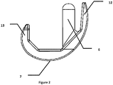
figure 2 est une représentation schématique d'une vue de côté longitudinal d'un condyle fémoral faisant partie d'un implant espaceur selon la présente invention, - la
figure 3 est une représentation schématique d'une vue de dessous d'un condyle fémoral faisant partie d'un implant espaceur selon la présente invention, - la
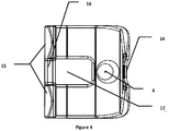
figure 4 est une représentation schématique d'une vue de dessus d'un condyle fémoral faisant partie d'un implant espaceur selon la présente invention, - la
figure 5 est une représentation schématique d'une vue en perspective d'un plateau tibial faisant partie d'un implant espaceur selon la présente invention, - la
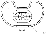
figure 6 est une représentation schématique d'une vue de dessous d'un plateau tibial faisant partie d'un implant espaceur selon la présente invention, - la
figure 7 est une représentation schématique d'une vue de dos d'un plateau tibial faisant partie d'un implant espaceur selon la présente invention, - la
figure 8 est une représentation schématique d'une vue de dos d'un implant espaceur selon la présente invention, - la
figure 9 est une représentation schématique d'une vue de côté longitudinal d'un implant espaceur selon la présente invention, - la
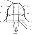
figure 10 est une représentation schématique d'une vue de face d'un implant espaceur selon la présente invention. - La
figure 1 montre un implant espaceur I de remplacement temporaire d'une prothèse de genou conformément à la présente invention. Cet implant espaceur I est composé de deux parties, à savoir un condyle fémoral 1 et un plateau tibial 2 qui sont mis en place pendant un temps nécessaire pour la guérison de l'infection et après une phase de cicatrisation. - Le plateau tibial 2 présente un corps principal formant plateau prolongé en dessous par une quille 10. Cette quille 10, s'étendant vers le bas en position montée de l'implant espaceur I, est destinée à être verrouillée, selon un moyen connu, dans l'extrémité supérieure du tibia d'un patient.
- Le plateau tibial 2 comprend aussi une cale de réglage 11 à sa partie inférieure. Cette cale 11 qui sert de réglage de hauteur du plateau tibial 1 peut être utilisée dans certains cas anatomiques. La cale 11 comporte une forme semblable à la partie inférieure du plateau tibial 2 et est appliquée contre celle-ci.
- La cale 11 forme alors une surépaisseur pour le plateau tibial 2 lorsque ce dernier n'est pas assez épais pour le patient. Cette cale 11 de réglage peut être en ciment PMMA et peut être chargée en antibiotique tel que la gentamicine par exemple. Avantageusement, la cale 11 peut également être armée par un renfort métallique biocompatible.
- Le corps principal du plateau tibial 2 est muni d'un réservoir interne débouchant par au moins une ouverture 4. Ce réservoir interne peut contenir une solution de substance médicamenteuse, par exemple à base d'antibiotiques. Cette substance est délivrée de manière progressive dans le temps pendant le positionnement provisoire de l'implant espaceur I afin de traiter l'infection du genou.
- Ceci s'applique aussi pour le condyle fémoral 1 qui peut aussi comprendre un réservoir 3. Un réservoir 3 peut encore être prévu sur le plateau tibial 1 et pénétrer dans la gorge 17 du condyle fémoral 1.
- Le traitement de l'infection du genou se fait couramment par l'administration d'un antibiotique et la présence de tels réservoirs 3 aident à l'application de ce traitement.
- Lesdits réservoirs peuvent être surmoulés dans l'implant I ou alors se présenter comme des capsules indépendantes qui peuvent être positionnées sur l'implant I dans des orifices prévus à cet effet.
- Ces réservoirs 3 peuvent être remplis in situ par le chirurgien avec un antibiotique, un anesthésiant ou encore un agent anti-infectieux. Ces différents additifs peuvent être sous forme liquide, solide ou gazeuse. Le chirurgien peut y injecter l'antibiotique de son choix ou un mélange d'antibiotiques et même un antibiotique différent dans chaque réservoir.
- L'implantation de ces réservoirs 3 peut être prévue à des endroits différents. Ces réservoirs 3 peuvent être aussi intégrés sur la quille tibiale 10 et/ou sur un plot 6 fémoral qui sera ultérieurement décrit. Il est possible de les intégrer en d'autres endroits du condyle fémoral 1, du plateau tibial 2 ou encore dans une cale 11.
- Il peut exister plusieurs volumes pour un réservoir 3, par exemple allant de 0.1 ml à 5 ml, de sorte que le relargage de l'antibiotique se fasse de manière répartie sur une durée donnée allant de 1 à 6 semaines. Ces réservoirs 3 peuvent être réalisés avec différents types de matériaux résorbables ou non, par exemple en PMMA ou matériau équivalent.
- Les implants qui existent aujourd'hui sont fabriqués en ciment PMMA chargé d'antibiotique pour le traitement local de l'infection en plus du traitement de fond.
- En alternative ou en complément à au moins un réservoir 3, l'implant I espaceur selon l'invention peut comporter des portions présentant une porosité différente, de telles portions permettant de mieux diffuser la substance médicamenteuse, avantageusement un ou des antibiotiques.
- Ainsi, un ou des matériaux de base de l'implant espaceur I peuvent être chargés en antibiotique permettant de traiter l'infection localement. Le ou les matériaux utilisés peuvent aussi être composés d'éléments opacifiants.
- Le condyle fémoral 1 va maintenant être décrit plus précisément en regard des
figures 1 à 4 . - Le condyle fémoral 1 présente une surface supérieure destinée à être tournée vers le fémur du patient d'une forme sensiblement concave.
- Le condyle fémoral 1 est formée de deux ailes latérales 12 et 13 recourbées vers le haut, donc en éloignement du plateau tibial 2 en étant réunies par une base 7. Une des ailes 12, 13 présente une plus grande longueur que l'autre aile latérale 13. Cette aile la plus longue 12 est appelée surface trochléenne.
- L'aile la plus longue 12 comporte sur sa partie extérieure une tranchée 14 longitudinale, appelée tranchée trochléenne. Cette tranchée 14 a pour effet de garantir la stabilité de la rotule et offre à la rotule un logement.
- Entre l'aile la plus longue 12 et la base 7, à la face supérieure du condyle fémoral 1, il est prévu un plot 6 faisant saillie vers le haut en position insérée de l'implant I dans le genou. Ce plot 6 pénètre dans l'extrémité inférieure du fémur du patient pour le maintien de l'implant I en place en coopération avec la quille 10 du plateau tibial 2 pénétrant dans le tibia du patient, afin que l'implant I remplisse efficacement la fonction d'articulation du genou du patient et soit ancré en deux points.
- Ainsi en se référant particulièrement à la
figure 1 , le condyle fémoral 1 et le plateau tibial 2 présentent respectivement un plot 6 et une quille 10 servant à la stabilisation de l'implant espaceur I, le plot 6 et la quille 10 s'encastrant dans la lumière de l'os. - Avantageusement, la quille 10 du plateau tibial 2 est de forme trapézoïdale et de section oblongue tandis que le plot 6 du condyle fémoral 1 est sensiblement cylindrique.
- Les fonctions du plot 6 et de la quille 10 sont donc d'une part de combler le vide laissé par la prothèse de genou défectueuse et par l'ablation de la partie infectée et d'autre part de stabiliser l'implant espaceur I en stabilisant un élément respectif dudit implant I, respectivement le condyle fémoral 1 ou le plateau tibial 2.
- La seconde aile latérale qui est l'aile plus courte 13 que la précédente aile 12 appelée surface trochléenne, porte deux éléments appelés condyles 15 reliés entre eux par une barre de stabilisation 16 s'étendant en direction transversale du condyle fémoral 1. Cette barre de stabilisation 16 réunissant les deux condyles 15 à l'extrémité libre de l'aile 13, coopère avec le pion 9 situé sur le plateau tibial 2 de telle sorte qu'elle permet d'éviter tout jeu latéral entre les deux condyles. Elle peut également faire office de butée pour le pion 9, ce qui permet de limiter le degré de rotation de l'articulation dans les mouvements de flexion selon un plan sagittal. Grâce à cette barre de stabilisation 16, le genou est comme « bloqué » à partir d'un certain degré de rotation, ce qui limite le mouvement de l'articulation, offrant une meilleure stabilité et surtout favorisant la résorption de l'infection et la cicatrisation.
- Avantageusement il est prévu une gorge 17 traversant de haut en bas une partie de la seconde surface latérale 13 et de la base 7 et s'étendant de la barre de solidarisation 16 vers un réservoir 3 situé sensiblement au pied du plot 6 pour son ancrage avec la base 7. Cette gorge 17 forme les moyens de réception portés par le condyle fémoral comme il sera vu par la suite.
- Avantageusement, le plot 6 du condyle fémoral 1 se trouve entre l'aile la plus longue 12 et la gorge 17 traversant la base 7 dudit condyle 1.
- Similairement au réservoir du plateau tibial 2, le réservoir 3 du condyle fémoral 1, muni d'une ouverture, peut contenir une solution à base d'antibiotiques qui est délivrée de manière progressive dans le temps pendant le positionnement provisoire de l'implant espaceur I afin de traiter l'infection du genou.
- La partie inférieure de la base 7 du condyle fémoral 1 vient s'appliquer contre la partie supérieure du plateau tibial 2 en position montée de l'implant I. La partie inférieure de la base 7 présente une forme sensiblement convexe pour un meilleur contact avec la partie supérieure du plateau tibial 2 qui est de forme concave.
- Les
figures 5 à 7 permettent de voir sur un plateau tibial 2 les moyens de positionnement du condyle fémoral 1 sur ledit plateau tibial 2. - La surface supérieure 8 du plateau tibial 2 présente une surface concave permettant la réception de la surface inférieure du condyle fémoral.
- Comme indiqué précédemment, la surface supérieure 8 du plateau tibial 2 présente un pion 9 dit pion de postéro-stabilisation pénétrant dans la partie inférieure de la base du condyle fémoral. En cas de flexion du genou selon un plan sagittal, les condyles 15 présentent un mouvement de rotation en glissant sur la face supérieure 8 du plateau tibial 2. Cette rotation est bloquée par la butée du pion 9 sur la barre de stabilisation 16 reliant les deux condyles 15 à l'extrémité libre de l'aile 13, favorisant la stabilité de l'articulation et la cicatrisation résultant de l'opération de reprise de l'implant infecté.
- Sur la
figure 8 , il peut être vu que le pion 9 de postéro-stabilisation du plateau tibial 2 pénètre dans des moyens de réception prévus pour le condyle fémoral 1, ces moyens étant constitués par la gorge 17. - De plus, sur la
figure 9 , il peut être vu que la surface inférieure convexe de la base 7 du condyle fémoral 1 est en appui sur la surface supérieure 8 concave du plateau tibial 2. La forme concave de la surface supérieure 8 du plateau tibial 2 et la forme convexe de la surface inférieure de la base 7 du condyle fémoral 1 garantissent une meilleure stabilité de l'implant lors de sa mise en mouvement. - En permettant au condyle fémoral 1 de rester bien en place par rapport au plateau tibial 2, le pion 9 de postéro-stabilisation présente l'avantage de pouvoir empêcher les luxations de l'articulation du genou. De plus, il peut simuler la fonction des ligaments croisés.
- Le condyle fémoral 1 dispose d'une accueille, formée par la gorge 17 qui reçoit le pion de postéro-stabilisation lors de l'assemblage de l'élément plateau tibial 2 avec l'élément condyle fémoral 1. Une alternative peut consister en un évidemment autre que la gorge 17.
- Sur la
figure 10 , il peut être vu que le réservoir à l'intérieur du plateau tibial 2 présente deux ouvertures 4 disposées de manière opposée sur un flanc dudit plateau 2. - Un tel implant espaceur I peut présenter plusieurs tailles afin qu'un chirurgien puisse disposer d'une grande flexibilité d'adaptation à l'anatomie du patient. L'adaptabilité de cette gamme de taille procure aussi un meilleur confort au patient.
Ceci vaut aussi pour la dimension de la quille 10 du plateau tibial 2 et/ou du plot 6 du condyle fémoral 1, ces éléments étant notamment visibles sur lafigure 1 . - Avantageusement, la quille 10 et/ou le plot 6 peuvent être amovibles de leur élément de support et peuvent être remplacés par d'autres quilles 10 ou plots 6 présentant des dimensions différentes, ce qui permet d'avoir une flexibilité satisfaisante et une meilleure stabilité pour l'implant I.
- Avantageusement, toujours en se référant notamment à la
figure 1 , le condyle fémoral 1 et le plateau tibial 2 ainsi que la cale 11 sont en matériaux renforcés, par exemple en étant constitués d'une armature avec des renforts métalliques afin de solidifier l'implant I. - L'implant espaceur I peut être réalisé en matériau biocompatible, disposant de caractéristiques mécaniques suffisantes afin que le patient puisse bénéficier d'une certaine autonomie de déambulation.
- En effet, il s'est avéré que pour plusieurs espaceurs de genou, ceux-ci montraient des défaillances dans leur résistance mécanique avec des ruptures suites à leur implantation. De telles ruptures sont susceptibles d'engendrer des débris qui peuvent détériorer l'environnement articulaire, comme par exemple les ligaments latéraux. Ceci peut être évité avec de tels renforts comme précédemment décrit.
- L'avantage principal de la présente invention est d'offrir une forme ergonomique et anatomique grâce à la reprise des caractéristiques générales du genou, que ce soit technique ou dimensionnelle, ce qui permet une bonne articulation du genou, ceci en gardant une certaine limite de mouvement, notamment en flexion selon un plan sagittal, pour ne pas perturber la cicatrisation. Un autre avantage réside dans la facilité de pose et de dépose de l'implant.
- Avec un tel implant, le confort et la déambulation contrôlée du patient sont améliorés, du fait de la qualité des états de surfaces fonctionnelles, ce qui limite la friction entre plateau tibial et condyle fémoral de l'implant et de l'adaptation anatomique de l'implant sur le patient. De plus un tel implant espaceur présente de bonnes propriétés de tenue mécanique.
Claims (9)
- Implant (I) espaceur de remplacement temporaire d'une prothèse de genou, cet implant (I), présentant un condyle fémoral (1) et un plateau tibial (2), la face inférieure (7) du condyle fémoral (1) reposant sur la face supérieure (8) du plateau tibial (2), la face inférieure (7) du condyle fémoral (1) étant de forme convexe tandis que la face supérieure (8) du plateau tibial (2) est de forme concave, un pion (9) porté par le plateau tibial (2) pénétrant dans des moyens de réception (17) prévus sur le condyle fémoral (1), le condyle fémoral (1) présentant deux ailes (12, 13) de tailles différentes et recourbées en éloignement du plateau tibial (2), les deux ailes (12, 13) étant réunies par une base (7) dont la partie inférieure forme la face inférieure du condyle fémoral (1), caractérisé en ce que la base (7) est traversée par une gorge (17) s'étendant dans la direction longitudinale du condyle fémoral (1), ladite gorge (17) formant les moyens de réception prévus sur le condyle fémoral (1), l'aile la plus courte (13) étant constituée de deux éléments (15) appelés condyles, disposés à distance l'un de l'autre en étant séparés par le prolongement de la gorge (17), une barre de stabilisation (16) réunissant les deux condyles (15) à l'extrémité libre de ladite aile (13).
- Implant (I) selon la revendication 1, pour lequel la face extérieure de l'aile la plus longue (12) comporte une tranchée (14) médiane longitudinale, dite tranchée trochléenne.
- Implant (I) selon la revendication 1 ou 2, pour lequel le condyle fémoral (1) et le plateau tibial (2) portent respectivement un plot (6) et une quille (10), le plot (6) et la quille (10) étant destinés à s'insérer dans l'os en vis-à-vis respectif du condyle ou du plateau.
- Implant (I) selon la revendication précédente, pour lequel le plot (6) du condyle fémoral (1) se trouve entre l'aile la plus longue (12) et la gorge (17) traversant la base (7) dudit condyle (1).
- Implant (I) selon l'une quelconque des deux revendications précédentes, pour lequel, selon l'anatomie du patient, le plot (6) et la quille (10) sont de différentes dimensions.
- Implant (I) selon l'une quelconque des revendications précédentes, pour lequel au moins le condyle fémoral (1) ou le plateau tibial (2) comporte un ou plusieurs réservoir (3) interne muni d'au moins une ouverture (4) pour la délivrance contrôlée dans le temps d'une substance médicamenteuse.
- Implant (I) selon l'une quelconque des revendications précédentes, pour lequel le ou les matériaux du condyle fémoral (1) ou du plateau tibial (2) sont poreux afin d'absorber puis de restituer une substance médicamenteuse.
- Implant (I) selon l'une quelconque des revendications précédentes, pour lequel une cale (11) de réglage est disposée sous la partie inférieure du plateau (2).
- Implant (I) selon l'une quelconque des revendications précédentes, pour lequel au moins le condyle fémoral (1) ou le plateau tibial (2) comporte des renforts métalliques.
Applications Claiming Priority (2)
| Application Number | Priority Date | Filing Date | Title |
|---|---|---|---|
| FR1253593A FR2989568B1 (fr) | 2012-04-19 | 2012-04-19 | Implant espaceur de remplacement temporaire d'une prothese de genou |
| PCT/FR2013/050871 WO2013156743A1 (fr) | 2012-04-19 | 2013-04-19 | Implant espaceur de remplacement temporaire d'une prothese de genou |
Publications (2)
| Publication Number | Publication Date |
|---|---|
| EP2838477A1 EP2838477A1 (fr) | 2015-02-25 |
| EP2838477B1 true EP2838477B1 (fr) | 2017-10-11 |
Family
ID=48430846
Family Applications (1)
| Application Number | Title | Priority Date | Filing Date |
|---|---|---|---|
| EP13722507.4A Active EP2838477B1 (fr) | 2012-04-19 | 2013-04-19 | Implant espaceur de remplacement temporaire d'une prothèse de genou |
Country Status (10)
| Country | Link |
|---|---|
| US (1) | US20150134068A1 (fr) |
| EP (1) | EP2838477B1 (fr) |
| CN (1) | CN104507420A (fr) |
| BR (1) | BR112014026133A2 (fr) |
| CA (1) | CA2870607A1 (fr) |
| ES (1) | ES2655839T3 (fr) |
| FR (1) | FR2989568B1 (fr) |
| IN (1) | IN2014MN02074A (fr) |
| PT (1) | PT2838477T (fr) |
| WO (1) | WO2013156743A1 (fr) |
Families Citing this family (16)
| Publication number | Priority date | Publication date | Assignee | Title |
|---|---|---|---|---|
| US20140277530A1 (en) * | 2013-03-15 | 2014-09-18 | Smed-Ta/Td, Llc | Fixation of bone implants |
| US9278002B2 (en) * | 2013-06-07 | 2016-03-08 | Gregory Merrell | Elbow antibiotic spacer implant |
| US10226348B2 (en) * | 2014-11-06 | 2019-03-12 | Cossington Limited | Adjustable modular spacer device for the articulation of the knee |
| CN104840273A (zh) * | 2015-05-21 | 2015-08-19 | 北京爱康宜诚医疗器材股份有限公司 | 假体部件及其制造方法 |
| US9839523B1 (en) * | 2016-06-10 | 2017-12-12 | Jared Ruben Hillel FORAN | Antibiotic dispensing spacer apparatus and method for infected total knee arthroplasty |
| IT201600075924A1 (it) * | 2016-07-20 | 2018-01-20 | Augusto Magagnoli | Dispositivo spaziatore modulare del corpo umano |
| EP3585317B1 (fr) * | 2017-02-27 | 2021-06-09 | Zimmer, Inc. | Systèmes d'implant de genou prothétique à rotation tibiale liée |
| CN110799151A (zh) * | 2017-06-23 | 2020-02-14 | 福卡斯特矫形外科公司 | 用于补救膝关节的方法、系统以及设备 |
| KR102574670B1 (ko) * | 2018-03-07 | 2023-09-05 | 코싱턴 리미티드 | 인체의 관절용 임시 스페이서 디바이스 |
| US10966838B2 (en) | 2019-02-28 | 2021-04-06 | Oxford Performance Materials, Inc. | Articulating knee spacer and method of manufacture |
| US11141291B2 (en) * | 2019-06-30 | 2021-10-12 | Depuy Ireland Unlimited Company | Femoral trial components and associated orthopaedic surgical method of use |
| US12521245B2 (en) * | 2019-07-24 | 2026-01-13 | Waldemar Link Gmbh & Co. Kg | Combination of augment and replacement piece for filling a bone defect |
| CN110538010B (zh) * | 2019-09-17 | 2024-05-28 | 北京爱康宜诚医疗器材有限公司 | 单髁膝关节假体 |
| CN111214314A (zh) * | 2020-03-03 | 2020-06-02 | 中国人民解放军陆军军医大学第二附属医院 | 活动型占位器 |
| WO2023051889A1 (fr) * | 2021-09-28 | 2023-04-06 | Hafez Mahmoud Alm El Din | Méga-écarteur pour perte osseuse grave et tumeur |
| AU2024226798A1 (en) | 2023-02-21 | 2025-09-04 | Osteal Therapeutics, Inc. | Methods of local irrigation for treating fungal infections |
Family Cites Families (15)
| Publication number | Priority date | Publication date | Assignee | Title |
|---|---|---|---|---|
| JPS6077752A (ja) * | 1983-09-30 | 1985-05-02 | 東海林 宏 | メニスカル人工膝関節 |
| DE3535112A1 (de) * | 1985-10-02 | 1987-04-16 | Witzel Ulrich | Tibiaplateauteil einer kniegelenkendoprothese |
| US5116375A (en) * | 1990-08-27 | 1992-05-26 | Hofmann Aaron A | Knee prosthesis |
| ITVI20000025U1 (it) * | 2000-04-07 | 2001-10-07 | Tecres Spa | Dispositivo distanziatore temporaneo per il trattamento chirurgico del ginocchio |
| EP1385456B1 (fr) * | 2001-04-17 | 2011-06-22 | Exactech, Inc. | Articulation de genou prothetique |
| US6896702B2 (en) * | 2002-05-10 | 2005-05-24 | Howmedica Osteonics Corp. | Securing an augment to a prosthetic implant component |
| US7427296B2 (en) * | 2003-11-14 | 2008-09-23 | Richard Parker Evans | Total knee joint mold and methods |
| FR2871678B1 (fr) * | 2004-06-17 | 2006-09-01 | Transysteme Sa | Prothese totale du genou |
| US7867426B2 (en) * | 2006-03-23 | 2011-01-11 | Ziran Bruce H | Method of forming a temporary implant |
| US7875081B2 (en) * | 2006-09-25 | 2011-01-25 | New York Society For The Ruptured And Crippled Maintaining The Hospital For Special Surgery | Posterior stabilized knee prosthesis |
| US8206451B2 (en) * | 2008-06-30 | 2012-06-26 | Depuy Products, Inc. | Posterior stabilized orthopaedic prosthesis |
| WO2010019781A1 (fr) * | 2008-08-13 | 2010-02-18 | Smed-Ta/Td, Llc | Implants permettant la délivrance de médicament |
| CN102548510B (zh) * | 2008-10-29 | 2015-04-01 | 捷迈骨科手术产品公司 | 具有可拆卸固定件的间隔件模具 |
| US9011547B2 (en) * | 2010-01-21 | 2015-04-21 | Depuy (Ireland) | Knee prosthesis system |
| CN201790919U (zh) * | 2010-09-21 | 2011-04-13 | 北京爱康宜诚医疗器材股份有限公司 | 带有加强筋的膝关节间隔器 |
-
2012
- 2012-04-19 FR FR1253593A patent/FR2989568B1/fr not_active Expired - Fee Related
-
2013
- 2013-04-19 US US14/395,405 patent/US20150134068A1/en not_active Abandoned
- 2013-04-19 CN CN201380021629.8A patent/CN104507420A/zh active Pending
- 2013-04-19 CA CA2870607A patent/CA2870607A1/fr not_active Abandoned
- 2013-04-19 PT PT137225074T patent/PT2838477T/pt unknown
- 2013-04-19 IN IN2074MUN2014 patent/IN2014MN02074A/en unknown
- 2013-04-19 ES ES13722507.4T patent/ES2655839T3/es active Active
- 2013-04-19 BR BR112014026133A patent/BR112014026133A2/pt not_active Application Discontinuation
- 2013-04-19 EP EP13722507.4A patent/EP2838477B1/fr active Active
- 2013-04-19 WO PCT/FR2013/050871 patent/WO2013156743A1/fr not_active Ceased
Non-Patent Citations (1)
| Title |
|---|
| None * |
Also Published As
| Publication number | Publication date |
|---|---|
| PT2838477T (pt) | 2018-01-16 |
| US20150134068A1 (en) | 2015-05-14 |
| BR112014026133A2 (pt) | 2017-06-27 |
| ES2655839T3 (es) | 2018-02-21 |
| FR2989568B1 (fr) | 2014-09-05 |
| EP2838477A1 (fr) | 2015-02-25 |
| CN104507420A (zh) | 2015-04-08 |
| FR2989568A1 (fr) | 2013-10-25 |
| WO2013156743A1 (fr) | 2013-10-24 |
| IN2014MN02074A (fr) | 2015-08-21 |
| CA2870607A1 (fr) | 2013-10-24 |
Similar Documents
| Publication | Publication Date | Title |
|---|---|---|
| WO2013156743A1 (fr) | Implant espaceur de remplacement temporaire d'une prothese de genou | |
| FR3071400B1 (fr) | Prothese de cheville comportant un implant talien, un implant tibial et un insert, kit incluant au moins une telle prothese, et guide de coupe pour la mise en place de l'implant tibial | |
| EP1813230B1 (fr) | Ensemble d'Instrumentation chirurgicale pour poser une prothèse de cheville | |
| JP6764966B2 (ja) | 骨インプラントの固定法 | |
| EP1025819B1 (fr) | Prothese totale du genou à insert mobile par rapport à un tenon | |
| BE1010569A6 (fr) | Systeme prothetique pour remplacer le ligament croise anterieur du genou et prothese modulaire semi-amovible du ligament croise anterieur du genou. | |
| US10463498B2 (en) | Constrained prosthesis for the knee joint | |
| EP3132758A1 (fr) | Sabot d'aide au positionnement et a la fixation d'un implant chirurgical | |
| US20170312087A1 (en) | Constrained Spacer Device For The Knee Joint | |
| FR2634373A1 (fr) | Prothese totale du genou | |
| KR20070058384A (ko) | 척추체의 부분적 교체를 위한 인공 보철물 | |
| EP3253334B1 (fr) | Prothese totale de genou avec couple de frottement ceramique sur ceramique et plateau mobile en ceramique | |
| CN103841923B (zh) | 用于人体的关节的临时模块式占位器装置 | |
| FR2961686A1 (fr) | Dispositif orthopedique destine a equiper l'articulation d'un genou. | |
| EP0567705A1 (fr) | Prothèse totale postéro-stabilisée du genou | |
| FR2717373A1 (fr) | Ensemble prothétique pour l'articulation du genou. | |
| EP3854355B1 (fr) | Composant implantable a moyen d'ancrage ameliore pour prothese de cheville et prothese de cheville comprenant un tel composant | |
| FR2796268A1 (fr) | Dispositif de maintien d'une ossature permettant de recevoir un produit de maintien et de comblement sans risque d'epandage de ce dernier a l'interieur du corps humain | |
| FR2630640A1 (fr) | Dispositif de prothese partielle du genou | |
| FR2630639A1 (fr) | Dispositif de prothese partielle du genou | |
| WO2006040434A2 (fr) | Prothese totale du genou et gamme d'elements permettant de constituer cette prothese | |
| WO2015052431A1 (fr) | Dispositif implantable d'arthrodèse vertébrale pour la fusion de deux vertèbres sus et sous jacentes | |
| FR3006167A1 (fr) | Perfectionnement aux protheses totales de genou et a leur procede de montage | |
| FR3057760A1 (fr) | Gamme pour prothese de genou | |
| FR3055538A1 (fr) | Implant tibial autobloquant |
Legal Events
| Date | Code | Title | Description |
|---|---|---|---|
| PUAI | Public reference made under article 153(3) epc to a published international application that has entered the european phase |
Free format text: ORIGINAL CODE: 0009012 |
|
| 17P | Request for examination filed |
Effective date: 20141016 |
|
| AK | Designated contracting states |
Kind code of ref document: A1 Designated state(s): AL AT BE BG CH CY CZ DE DK EE ES FI FR GB GR HR HU IE IS IT LI LT LU LV MC MK MT NL NO PL PT RO RS SE SI SK SM TR |
|
| AX | Request for extension of the european patent |
Extension state: BA ME |
|
| DAX | Request for extension of the european patent (deleted) | ||
| GRAP | Despatch of communication of intention to grant a patent |
Free format text: ORIGINAL CODE: EPIDOSNIGR1 |
|
| INTG | Intention to grant announced |
Effective date: 20170406 |
|
| GRAS | Grant fee paid |
Free format text: ORIGINAL CODE: EPIDOSNIGR3 |
|
| GRAA | (expected) grant |
Free format text: ORIGINAL CODE: 0009210 |
|
| RAP1 | Party data changed (applicant data changed or rights of an application transferred) |
Owner name: TEKNIMED |
|
| AK | Designated contracting states |
Kind code of ref document: B1 Designated state(s): AL AT BE BG CH CY CZ DE DK EE ES FI FR GB GR HR HU IE IS IT LI LT LU LV MC MK MT NL NO PL PT RO RS SE SI SK SM TR |
|
| REG | Reference to a national code |
Ref country code: GB Ref legal event code: FG4D Free format text: NOT ENGLISH |
|
| REG | Reference to a national code |
Ref country code: CH Ref legal event code: EP |
|
| REG | Reference to a national code |
Ref country code: IE Ref legal event code: FG4D Free format text: LANGUAGE OF EP DOCUMENT: FRENCH |
|
| REG | Reference to a national code |
Ref country code: AT Ref legal event code: REF Ref document number: 935360 Country of ref document: AT Kind code of ref document: T Effective date: 20171115 |
|
| REG | Reference to a national code |
Ref country code: DE Ref legal event code: R096 Ref document number: 602013027779 Country of ref document: DE |
|
| REG | Reference to a national code |
Ref country code: PT Ref legal event code: SC4A Ref document number: 2838477 Country of ref document: PT Date of ref document: 20180116 Kind code of ref document: T Free format text: AVAILABILITY OF NATIONAL TRANSLATION Effective date: 20180110 |
|
| REG | Reference to a national code |
Ref country code: NL Ref legal event code: MP Effective date: 20171011 |
|
| REG | Reference to a national code |
Ref country code: ES Ref legal event code: FG2A Ref document number: 2655839 Country of ref document: ES Kind code of ref document: T3 Effective date: 20180221 |
|
| REG | Reference to a national code |
Ref country code: LT Ref legal event code: MG4D |
|
| REG | Reference to a national code |
Ref country code: AT Ref legal event code: MK05 Ref document number: 935360 Country of ref document: AT Kind code of ref document: T Effective date: 20171011 |
|
| PG25 | Lapsed in a contracting state [announced via postgrant information from national office to epo] |
Ref country code: NL Free format text: LAPSE BECAUSE OF FAILURE TO SUBMIT A TRANSLATION OF THE DESCRIPTION OR TO PAY THE FEE WITHIN THE PRESCRIBED TIME-LIMIT Effective date: 20171011 |
|
| REG | Reference to a national code |
Ref country code: FR Ref legal event code: PLFP Year of fee payment: 6 |
|
| PG25 | Lapsed in a contracting state [announced via postgrant information from national office to epo] |
Ref country code: FI Free format text: LAPSE BECAUSE OF FAILURE TO SUBMIT A TRANSLATION OF THE DESCRIPTION OR TO PAY THE FEE WITHIN THE PRESCRIBED TIME-LIMIT Effective date: 20171011 Ref country code: LT Free format text: LAPSE BECAUSE OF FAILURE TO SUBMIT A TRANSLATION OF THE DESCRIPTION OR TO PAY THE FEE WITHIN THE PRESCRIBED TIME-LIMIT Effective date: 20171011 Ref country code: NO Free format text: LAPSE BECAUSE OF FAILURE TO SUBMIT A TRANSLATION OF THE DESCRIPTION OR TO PAY THE FEE WITHIN THE PRESCRIBED TIME-LIMIT Effective date: 20180111 Ref country code: SE Free format text: LAPSE BECAUSE OF FAILURE TO SUBMIT A TRANSLATION OF THE DESCRIPTION OR TO PAY THE FEE WITHIN THE PRESCRIBED TIME-LIMIT Effective date: 20171011 |
|
| PG25 | Lapsed in a contracting state [announced via postgrant information from national office to epo] |
Ref country code: GR Free format text: LAPSE BECAUSE OF FAILURE TO SUBMIT A TRANSLATION OF THE DESCRIPTION OR TO PAY THE FEE WITHIN THE PRESCRIBED TIME-LIMIT Effective date: 20180112 Ref country code: AT Free format text: LAPSE BECAUSE OF FAILURE TO SUBMIT A TRANSLATION OF THE DESCRIPTION OR TO PAY THE FEE WITHIN THE PRESCRIBED TIME-LIMIT Effective date: 20171011 Ref country code: HR Free format text: LAPSE BECAUSE OF FAILURE TO SUBMIT A TRANSLATION OF THE DESCRIPTION OR TO PAY THE FEE WITHIN THE PRESCRIBED TIME-LIMIT Effective date: 20171011 Ref country code: BG Free format text: LAPSE BECAUSE OF FAILURE TO SUBMIT A TRANSLATION OF THE DESCRIPTION OR TO PAY THE FEE WITHIN THE PRESCRIBED TIME-LIMIT Effective date: 20180111 Ref country code: RS Free format text: LAPSE BECAUSE OF FAILURE TO SUBMIT A TRANSLATION OF THE DESCRIPTION OR TO PAY THE FEE WITHIN THE PRESCRIBED TIME-LIMIT Effective date: 20171011 Ref country code: LV Free format text: LAPSE BECAUSE OF FAILURE TO SUBMIT A TRANSLATION OF THE DESCRIPTION OR TO PAY THE FEE WITHIN THE PRESCRIBED TIME-LIMIT Effective date: 20171011 Ref country code: IS Free format text: LAPSE BECAUSE OF FAILURE TO SUBMIT A TRANSLATION OF THE DESCRIPTION OR TO PAY THE FEE WITHIN THE PRESCRIBED TIME-LIMIT Effective date: 20180211 |
|
| REG | Reference to a national code |
Ref country code: DE Ref legal event code: R097 Ref document number: 602013027779 Country of ref document: DE |
|
| PG25 | Lapsed in a contracting state [announced via postgrant information from national office to epo] |
Ref country code: DK Free format text: LAPSE BECAUSE OF FAILURE TO SUBMIT A TRANSLATION OF THE DESCRIPTION OR TO PAY THE FEE WITHIN THE PRESCRIBED TIME-LIMIT Effective date: 20171011 Ref country code: SK Free format text: LAPSE BECAUSE OF FAILURE TO SUBMIT A TRANSLATION OF THE DESCRIPTION OR TO PAY THE FEE WITHIN THE PRESCRIBED TIME-LIMIT Effective date: 20171011 Ref country code: CZ Free format text: LAPSE BECAUSE OF FAILURE TO SUBMIT A TRANSLATION OF THE DESCRIPTION OR TO PAY THE FEE WITHIN THE PRESCRIBED TIME-LIMIT Effective date: 20171011 Ref country code: EE Free format text: LAPSE BECAUSE OF FAILURE TO SUBMIT A TRANSLATION OF THE DESCRIPTION OR TO PAY THE FEE WITHIN THE PRESCRIBED TIME-LIMIT Effective date: 20171011 |
|
| PGFP | Annual fee paid to national office [announced via postgrant information from national office to epo] |
Ref country code: IE Payment date: 20180427 Year of fee payment: 6 Ref country code: PT Payment date: 20180418 Year of fee payment: 6 |
|
| PLBE | No opposition filed within time limit |
Free format text: ORIGINAL CODE: 0009261 |
|
| STAA | Information on the status of an ep patent application or granted ep patent |
Free format text: STATUS: NO OPPOSITION FILED WITHIN TIME LIMIT |
|
| PG25 | Lapsed in a contracting state [announced via postgrant information from national office to epo] |
Ref country code: PL Free format text: LAPSE BECAUSE OF FAILURE TO SUBMIT A TRANSLATION OF THE DESCRIPTION OR TO PAY THE FEE WITHIN THE PRESCRIBED TIME-LIMIT Effective date: 20171011 Ref country code: RO Free format text: LAPSE BECAUSE OF FAILURE TO SUBMIT A TRANSLATION OF THE DESCRIPTION OR TO PAY THE FEE WITHIN THE PRESCRIBED TIME-LIMIT Effective date: 20171011 Ref country code: SM Free format text: LAPSE BECAUSE OF FAILURE TO SUBMIT A TRANSLATION OF THE DESCRIPTION OR TO PAY THE FEE WITHIN THE PRESCRIBED TIME-LIMIT Effective date: 20171011 |
|
| PGFP | Annual fee paid to national office [announced via postgrant information from national office to epo] |
Ref country code: TR Payment date: 20180418 Year of fee payment: 6 |
|
| 26N | No opposition filed |
Effective date: 20180712 |
|
| PG25 | Lapsed in a contracting state [announced via postgrant information from national office to epo] |
Ref country code: MT Free format text: LAPSE BECAUSE OF FAILURE TO SUBMIT A TRANSLATION OF THE DESCRIPTION OR TO PAY THE FEE WITHIN THE PRESCRIBED TIME-LIMIT Effective date: 20171011 |
|
| PG25 | Lapsed in a contracting state [announced via postgrant information from national office to epo] |
Ref country code: SI Free format text: LAPSE BECAUSE OF FAILURE TO SUBMIT A TRANSLATION OF THE DESCRIPTION OR TO PAY THE FEE WITHIN THE PRESCRIBED TIME-LIMIT Effective date: 20171011 Ref country code: MC Free format text: LAPSE BECAUSE OF FAILURE TO SUBMIT A TRANSLATION OF THE DESCRIPTION OR TO PAY THE FEE WITHIN THE PRESCRIBED TIME-LIMIT Effective date: 20171011 |
|
| REG | Reference to a national code |
Ref country code: BE Ref legal event code: MM Effective date: 20180430 |
|
| PG25 | Lapsed in a contracting state [announced via postgrant information from national office to epo] |
Ref country code: LU Free format text: LAPSE BECAUSE OF NON-PAYMENT OF DUE FEES Effective date: 20180419 |
|
| PG25 | Lapsed in a contracting state [announced via postgrant information from national office to epo] |
Ref country code: BE Free format text: LAPSE BECAUSE OF NON-PAYMENT OF DUE FEES Effective date: 20180430 |
|
| PGFP | Annual fee paid to national office [announced via postgrant information from national office to epo] |
Ref country code: ES Payment date: 20190517 Year of fee payment: 7 Ref country code: DE Payment date: 20190415 Year of fee payment: 7 Ref country code: IT Payment date: 20190411 Year of fee payment: 7 |
|
| PGFP | Annual fee paid to national office [announced via postgrant information from national office to epo] |
Ref country code: CH Payment date: 20190424 Year of fee payment: 7 |
|
| PGFP | Annual fee paid to national office [announced via postgrant information from national office to epo] |
Ref country code: GB Payment date: 20190424 Year of fee payment: 7 |
|
| PG25 | Lapsed in a contracting state [announced via postgrant information from national office to epo] |
Ref country code: PT Free format text: LAPSE BECAUSE OF NON-PAYMENT OF DUE FEES Effective date: 20191021 |
|
| PG25 | Lapsed in a contracting state [announced via postgrant information from national office to epo] |
Ref country code: IE Free format text: LAPSE BECAUSE OF NON-PAYMENT OF DUE FEES Effective date: 20190419 |
|
| PG25 | Lapsed in a contracting state [announced via postgrant information from national office to epo] |
Ref country code: HU Free format text: LAPSE BECAUSE OF FAILURE TO SUBMIT A TRANSLATION OF THE DESCRIPTION OR TO PAY THE FEE WITHIN THE PRESCRIBED TIME-LIMIT; INVALID AB INITIO Effective date: 20130419 |
|
| PG25 | Lapsed in a contracting state [announced via postgrant information from national office to epo] |
Ref country code: CY Free format text: LAPSE BECAUSE OF FAILURE TO SUBMIT A TRANSLATION OF THE DESCRIPTION OR TO PAY THE FEE WITHIN THE PRESCRIBED TIME-LIMIT Effective date: 20171011 Ref country code: MK Free format text: LAPSE BECAUSE OF NON-PAYMENT OF DUE FEES Effective date: 20171011 |
|
| PG25 | Lapsed in a contracting state [announced via postgrant information from national office to epo] |
Ref country code: AL Free format text: LAPSE BECAUSE OF FAILURE TO SUBMIT A TRANSLATION OF THE DESCRIPTION OR TO PAY THE FEE WITHIN THE PRESCRIBED TIME-LIMIT Effective date: 20171011 |
|
| REG | Reference to a national code |
Ref country code: DE Ref legal event code: R119 Ref document number: 602013027779 Country of ref document: DE |
|
| REG | Reference to a national code |
Ref country code: CH Ref legal event code: PL |
|
| PG25 | Lapsed in a contracting state [announced via postgrant information from national office to epo] |
Ref country code: LI Free format text: LAPSE BECAUSE OF NON-PAYMENT OF DUE FEES Effective date: 20200430 Ref country code: DE Free format text: LAPSE BECAUSE OF NON-PAYMENT OF DUE FEES Effective date: 20201103 Ref country code: CH Free format text: LAPSE BECAUSE OF NON-PAYMENT OF DUE FEES Effective date: 20200430 |
|
| GBPC | Gb: european patent ceased through non-payment of renewal fee |
Effective date: 20200419 |
|
| PG25 | Lapsed in a contracting state [announced via postgrant information from national office to epo] |
Ref country code: GB Free format text: LAPSE BECAUSE OF NON-PAYMENT OF DUE FEES Effective date: 20200419 |
|
| REG | Reference to a national code |
Ref country code: ES Ref legal event code: FD2A Effective date: 20210903 |
|
| PG25 | Lapsed in a contracting state [announced via postgrant information from national office to epo] |
Ref country code: IT Free format text: LAPSE BECAUSE OF NON-PAYMENT OF DUE FEES Effective date: 20200419 |
|
| PG25 | Lapsed in a contracting state [announced via postgrant information from national office to epo] |
Ref country code: ES Free format text: LAPSE BECAUSE OF NON-PAYMENT OF DUE FEES Effective date: 20200420 |
|
| PG25 | Lapsed in a contracting state [announced via postgrant information from national office to epo] |
Ref country code: TR Free format text: LAPSE BECAUSE OF NON-PAYMENT OF DUE FEES Effective date: 20190419 |
|
| PGFP | Annual fee paid to national office [announced via postgrant information from national office to epo] |
Ref country code: FR Payment date: 20260217 Year of fee payment: 14 |