EP2838355B2 - Feed gripping device - Google Patents
Feed gripping device Download PDFInfo
- Publication number
- EP2838355B2 EP2838355B2 EP13713558.8A EP13713558A EP2838355B2 EP 2838355 B2 EP2838355 B2 EP 2838355B2 EP 13713558 A EP13713558 A EP 13713558A EP 2838355 B2 EP2838355 B2 EP 2838355B2
- Authority
- EP
- European Patent Office
- Prior art keywords
- feed
- grab bucket
- pile
- gripping device
- control unit
- Prior art date
- Legal status (The legal status is an assumption and is not a legal conclusion. Google has not performed a legal analysis and makes no representation as to the accuracy of the status listed.)
- Active
Links
- 238000005303 weighing Methods 0.000 claims description 25
- 238000003860 storage Methods 0.000 claims description 8
- 238000006073 displacement reaction Methods 0.000 claims description 7
- 238000010586 diagram Methods 0.000 description 23
- 230000008901 benefit Effects 0.000 description 12
- 239000000463 material Substances 0.000 description 11
- 238000005259 measurement Methods 0.000 description 9
- 239000004460 silage Substances 0.000 description 9
- 241001465754 Metazoa Species 0.000 description 6
- 238000005520 cutting process Methods 0.000 description 5
- 240000008042 Zea mays Species 0.000 description 3
- 235000016383 Zea mays subsp huehuetenangensis Nutrition 0.000 description 3
- 235000002017 Zea mays subsp mays Nutrition 0.000 description 3
- 235000009973 maize Nutrition 0.000 description 3
- 238000002604 ultrasonography Methods 0.000 description 3
- 238000004891 communication Methods 0.000 description 2
- 230000001419 dependent effect Effects 0.000 description 2
- 238000009826 distribution Methods 0.000 description 2
- 230000000694 effects Effects 0.000 description 2
- 238000000034 method Methods 0.000 description 2
- 238000012545 processing Methods 0.000 description 2
- 238000009825 accumulation Methods 0.000 description 1
- 230000032683 aging Effects 0.000 description 1
- 238000013459 approach Methods 0.000 description 1
- 235000013339 cereals Nutrition 0.000 description 1
- 238000006243 chemical reaction Methods 0.000 description 1
- 238000004140 cleaning Methods 0.000 description 1
- 238000001035 drying Methods 0.000 description 1
- 239000000428 dust Substances 0.000 description 1
- 235000013312 flour Nutrition 0.000 description 1
- 239000007788 liquid Substances 0.000 description 1
- 230000007257 malfunction Effects 0.000 description 1
- 239000000203 mixture Substances 0.000 description 1
- 230000035515 penetration Effects 0.000 description 1
- 239000000843 powder Substances 0.000 description 1
- 238000013341 scale-up Methods 0.000 description 1
- 239000010902 straw Substances 0.000 description 1
Images


Classifications
-
- A—HUMAN NECESSITIES
- A01—AGRICULTURE; FORESTRY; ANIMAL HUSBANDRY; HUNTING; TRAPPING; FISHING
- A01K—ANIMAL HUSBANDRY; AVICULTURE; APICULTURE; PISCICULTURE; FISHING; REARING OR BREEDING ANIMALS, NOT OTHERWISE PROVIDED FOR; NEW BREEDS OF ANIMALS
- A01K5/00—Feeding devices for stock or game ; Feeding wagons; Feeding stacks
- A01K5/02—Automatic devices
- A01K5/0266—Automatic devices with stable trolleys, e.g. suspended
Definitions
- the invention relates to a feed gripping device for gripping feed from a feed storage location containing one or more piles of feed, and comprising a frame and a grab bucket carrier which is displaceable with at least one horizontal degree of freedom with respect to said frame, as well as a grab bucket which is vertically displaceable with respect to the grab bucket carrier, furthermore comprising at least one sensor which is operatively connected to the gripping device and is arranged to determine a value of at least one parameter which relates to at least one pile of feed at the feed storage location, as well as a control unit which is operatively connected to the gripping device and the sensor and which is arranged to control the gripping device on the basis of the measured value of the parameter.
- EP2129214 discloses a device for gripping and displacing material.
- This device is provided with content-determining means for determining the weight and/or the volume of the material present in, for example, a milking robot feeding location and for emitting a quantity or weight signal, respectively, to the control means.
- content-determining means for determining the weight and/or the volume of the material present in, for example, a milking robot feeding location and for emitting a quantity or weight signal, respectively, to the control means.
- the disclosed device or assembly appears to comprise predetermined information regarding the height distribution and/or the volume of the material, as well as a comparator which is arranged to compare the image of the material obtained by a sensor with the predetermined information.
- a comparator which is arranged to compare the image of the material obtained by a sensor with the predetermined information.
- control means thereof are activated automatically by the signals emitted by the aforementioned sensor, in such a manner that, if there is a difference in height of the material to be gripped, the material which is at the highest or almost at the highest level is gripped first and/or the material is dumped in the location where the level is at the lowest or almost at the lowest level. Therefore, control takes place on the basis of a parameter value relating to a pile of feed, but only to determine the location where gripping takes place.
- EP2232982 discloses a device for cutting silage.
- This device is provided with a laser scanner which obtains data representing the form of the front part of a silage pile.
- the system also includes dosing data which indicate how much silage is required from the silage pile.
- cutting position data are calculated representing a cutting position of the silage cutter frame, such that a calculated amount of silage between the cutting trajectory of the silage cutter associated with the calculated cutting position and an outer surface portion of the front part of the silage pile represented by the form data equals the amount of silage represented by the dosing data.
- a feed gripping device for gripping feed from a feed storage location containing one or more piles of feed, and comprising a frame and a grab bucket carrier which is displaceable with at least one horizontal degree of freedom with respect to said frame, as well as a grab bucket which is vertically displaceable with respect to the grab bucket carrier, furthermore comprising at least one sensor which is operatively connected to the gripping device and is arranged to determine a value of at least one parameter which relates to at least one pile of feed at the feed storage location, as well as a control unit which is operatively connected to the gripping device and the sensor and which is arranged to control the gripping device on the basis of the measured value of the parameter, wherein the control unit is arranged to determine and set, on the basis of the measured value of the parameter, a grabbing depth with respect to the at least one pile of feed, at which grabbing depth the control unit makes the grab bucket grab feed from the pile and , the control unit contains
- the gripping device is thus provided which has the advantage that it is possible to dynamically take changing circumstances into account. After all, it is not only the changing shape of a pile of feed, with the associated height information which is measured and processed by the control unit, which may after all affect the actual amount of feed which is ultimately grabbed.
- a changing density for example, due to grabbing or other changing circumstances such as drying, ageing, collapsing, etc. may also have an effect which can be processed.
- changes due to admixing or removing feed or any other relevant information is thus made available to the control unit. Due to the measured weight of the grabbed feed being passed on, the latest and most accurate information is always available for determining and setting the grabbing depth.
- the weight relates to the weight of an unloaded part, and more preferably the part collected in a collecting location, of the grabbed feed, as this provides even more accurate information.
- Updating may then comprise replacing the existing information with the new information, for example, by scaling up a standard graph on the basis of a new set of values (weight, grabbing depth). It is also possible to take a running average or weighted average or use any other suitable method of updating. In an embodiment, updating takes place every time the grab bucket has grabbed feed. After all, due to the digging and the like of the grab bucket the density, the profile, etc., of the feed may also change when the grab bucket grabs, but has to unload again prematurely because the weight is too low or too high.
- Such information stored may comprise, for example, a density function, a grabbed volume as a function of the grabbing depth, the type of feed, etc.
- the information may be regarded as having been stored if it is available at the point in time when the grabbing depth is to be calculated or set.
- This may be information which is collected or obtained only a short time beforehand, but also, for example, information which may be regarded as a standard setting, for example, in case the feed gripping device always has to grab the same type of feed, etc.
- the control unit is arranged to set the grabbing height by means of the stored information as well as the obtained value(s) of the parameter(s), and obviously the desired amount of feed.
- control unit is arranged to receive or calculate a desired amount of feed to be grabbed. Based on this, the control unit is then able to determine the required grabbing depth from information about the type of feed, density, etc.
- control unit may of course receive a "hard" instruction regarding a grabbing depth, optionally in the form of an absolute grabbing height.
- setting a grabbing depth is to be seen as equal to setting of a volume to be grabbed. Since there is a one-to-one relationship between a grabbed volume and the grabbing depth associated with said grabbing operation, means that setting one also sets the other. Obviously, the one-to-one relationship itself may depend once more on the type of feed, for example, because a liquid behaves differently from a coarse-crumbly or long-stemmed material when filling the grab bucket, but it is the correlation between grabbing depth and volume to be grabbed which is the point here.
- the gripping device which is thus provided measures a parameter of the pile of feed, the value thereof being used to predetermine to which depth the grab bucket has to dig into the pile of feed.
- this device will grab a(n almost) perfect amount of feed much more often. As a result thereof, less of a mess is made of the feed, and the remaining feed can be kept in its original compact shape, such as a bale or block, for longer. This in turn has the effect that the feed is better protected against rotting.
- Yet another advantage is the fact that the device, by more often grabbing the correct amount of feed, has a greater and/or more reliable capacity, since the grab bucket does not have to go to a feed-unloading point so often, at least not unnecessarily. Due to the fact that it is now possible to choose an amount in a much more targeted manner, it will be simple to ensure that only the minimum number of "rides" is made to said feed-unloading point.
- the feed gripping device may be unmanned and autonomous, which obviously offers advantages in terms of saving in labour. Nevertheless, even with feed gripping devices operated by humans, the present invention can still offer advantages, in particular in accurately grabbing a desired amount of feed.
- the term "pile” in this case comprises any accumulation, such as a trough, stack, heap or bale of the feed.
- the vertical displacement of the grab bucket does not mean that it moves only upwards and downwards at right angles, but it may also be displaceable obliquely, provided there is a vertical component to the movement. Obviously, a purely vertical movement may be advantageous, for example due to the fact that control thereof is simple.
- the parameter is or comprises absolute and/or relative height information relating to the pile of feed.
- the expression absolute height information is understood to mean height information with respect to a fixed point, and in particular to the ground or floor.
- absolute height information By collecting, for example, the height information of the pile of feed with respect to the ground, i.e. absolute height information, it is also possible to determine a grabbing depth by adapting the level of the grab bucket during grabbing to the absolute height information.
- the expression relative height information is understood to mean height information without an absolute reference. For example, a local point of contact which is reached when the grab bucket is lowered onto the pile of feed may be used as a starting point.
- grabbing depth will be considered identical to "grabbing height” below.
- grabbing height By collecting such height information, it is possible to provide quantity information about the pile of feed, at least a part of which is to be grabbed, in an efficient and accurate manner.
- these are parameters which can be measured relatively easily and accurately, as will be explained further below. Nevertheless, other parameters are not excluded, such as the weight of the pile which can be measured by a local weighing device situated under the pile or by a counting device in the case of a pile of countable feed.
- the type of feed in the pile is also very important in order to determine which grabbing depth is required for a desired amount of feed. However, this parameter does not vary greatly.
- the parameter comprises at least one of the following: the height of the pile, the local height of the pile vertically underneath the grab bucket, the average height of the pile, the local average height of the pile vertically underneath the grab bucket, at least one 1-dimensional height profile of the pile, and a 2-dimensional height profile of the pile.
- "vertically underneath the grab bucket” in fact means “in line with the movement of the grab bucket” which, after all, does not have to move downwards completely at right angles, as has been mentioned. It would also be possible to say "within reach of the grab bucket", obviously after the latter has moved sufficiently far towards the pile, so that the spatial dimensions of the grab bucket with respect to the pile of feed are included.
- a "1-dimensional height profile” or “2-dimensional height profile” in the present application means a height profile as a function of 1 coordinate or of 2 coordinates, respectively, in which case the profile itself obviously relates to a surface in the space, namely the external surface of the pile of feed.
- the parameters mentioned here can be used more specifically to predetermine the amount of feed to be grabbed. For example, if the local, optionally average, height of the pile of feed underneath the grab bucket is known, this can result in more accurate gripping results than if only a (greatest) height thereof is used. In turn, if the height profile is known in 1 dimension and better still in 2 dimensions, this will yield even more accurate results, since knowledge of the complete distribution and/or the volume of the pile situated underneath, again optionally and preferably underneath the grab bucket, will make it possible to estimate the amount of feed which has actually been grabbed very accurately.
- the parameter comprises height information as a function of the horizontal position of the grab bucket with respect to the pile of feed.
- the height may vary across the pile of feed, so that locally different absolute heights or grabbing depths are necessary in order to grab a desired amount of feed.
- a 1-dimensional profile provides such height information as a function of the position, in which case a 2-dimensional profile may be viewed as "a 1-dimensional profile in a first direction as a function of a second, different direction".
- the at least one sensor comprises a height meter and/or distance meter.
- the grabbing depth can in this case be regarded as the height at which the grab bucket grabs. This grabbing height corresponds to, at least is associated with, a desired grabbing depth in the pile of feed. This means that when a specific grabbing height has to be set, it is possible to achieve exactly the same by setting an associated grabbing depth in the pile of feed.
- a grabbing height refers more to an absolute height, such as above ground level
- a grabbing depth refers more to the surface of the pile of feed itself.
- the grab bucket has to dig into the pile of feed over a certain adjustable distance.
- This difference in approach may be useful depending on the sensor which is used in order to provide height information and on the position where this is located.
- Examples of the abovementioned sensor are also a laser distance meter or feeler or the like. These are able to provide the desired height information in a simple but accurate manner, in particular information relating to a relative height, such as distance between sensor and (local or global) height of the pile of feed.
- the at least one sensor comprises a 3D sensor.
- a 3D sensor can provide a spatial image of, for example, the height profile of the pile of feed in one go, and preferably substantially in real time, from which the desired height information can be taken.
- 3D sensors are 3D cameras and ultrasound sensors, in each case with image-processing means to convert the signals received by the 3D sensor into the desired image, at least into the desired information. It should be noted that with such 3D sensors as well, scanning or measuring during or after displacement may be advantageous. Not only is it thus possible to measure even large feeding stations efficiently and more quickly, but it is also possible to obtain a more reliable measurement of one and the same pile of feed, for example, if the image is covered for some reason.
- the higher scanning speed is an advantage, since this makes it possible to monitor which feeding stations need to be cleaned in a very efficient and dynamic way. Consequently, no time is lost at the start of the cleaning operation with determining which feeding station(s) has have to be cleaned.
- the 3D camera can nevertheless scan one or more feeding stations and collect the associated information, such as the height profile. Processing of the information may be carried out during further operations, such as grabbing of feed, so that the computed, processed information is almost immediately ready for a large number, if not all, feeding stations.
- the location where the sensor(s) is (are) provided there are no particular limitations with regard to the location where the sensor(s) is (are) provided. Nevertheless, in embodiments at least one of the at least one sensor is provided at the feed storage location or the frame.
- the sensor is therefore arranged in a fixed position. Thus, it is in particular possible to reliably carry out absolute height measurements without frequent calibration for a relatively long period of time.
- the sensor is then, for example, arranged on a separately provided pillar or frame or on the frame of the feed gripping device.
- the latter frame is, for example, a frame of an overhead crane or, if the feed gripping device comprises a crane which can be displaced in its entirety, a guide along which the feed gripping device is displaceable.
- At least one of the at least one sensor is provided on at least one of the grab bucket carrier and the grab bucket.
- This offers the advantage that the sensor, and in particular a measuring or image field thereof, is directed towards and situated close to the pile of feed to be measured.
- very accurate measurements are possible which are not or hardly affected by other piles of feed or obstacles which hamper or prevent a measurement or which render the latter inaccurate due to an excessive measuring distance.
- it is thus possible to carry out each measurement under the same conditions, such as measuring distance and angle. If the sensor is arranged on the grab bucket carrier, then the information obtained can still be regarded as being reasonably reliable absolute height information. If this sensor is built into, attached onto or on the grab bucket, the sensor in principle provides relative height information.
- the height information provided by the sensor arranged on the grab bucket may, if desired, again be regarded as absolute information after conversion. It is also advantageous if the control unit of the device is arranged on the grab bucket carrier and/or the grab bucket, at least advantageously in a substantially fixed position with respect to the sensor. Because the distance between the sensor and the control unit is then also fixed, very few, if any, communication problems will occur between the sensor and the control unit, which improves the reliability compared to an arrangement with variable distance.
- At least one of the at least one sensor is arranged to repeatedly measure a local height. This relates in particular to the repeated measuring during a single grabbing operation or grab bucket displacement operation, in order thus to be able to measure the desired parameter more accurately.
- said sensor is furthermore arranged to determine a 1-dimensional or 2-dimensional height profile of the pile of feed therefrom, more particularly during horizontal displacement of the grab bucket(/carrier).
- control unit and/or at least one of the at least one sensor is arranged to determine a parameter value for several piles of feed.
- the feed gripping device for example, not only measures the pile of feed from which feed is taken.
- the device may also collect height information for one or more, optionally adjacent, piles of feed, and optionally store it internally or externally. This renders a subsequent grabbing operation quicker as the relevant information is then already available.
- this measurement may possibly be less reliable. In that case, it is advisable to use this feature in particular when the piles of feed which are to be measured will hardly undergo any change.
- the information comprises a function or table, wherein the control unit is arranged to provide or calculate an associated grabbing height on the basis of the information for the desired amount of feed.
- the function or table may also be a program or logic circuit etc. with a corresponding function.
- the function or table is a density function or table which provides the density of the feed, at least of the pile. This density may itself also be a function of another variable or, in other words, be variable.
- the moisture content may have a great influence, as does the feed type itself, but also the compactness thereof. After all, the latter may change generally or locally in the pile of feed, inter alia as a result of previous grabbing operations and the like.
- the feed gripping device comprises a weighing sensor which is operatively connected to the control unit for determining the weight of a grabbed amount of feed. It is possible, on the basis of the actually grabbed feed, of which the weighing sensor determines the weight, to check if the feed gripping device works sufficiently accurately, and to accurately compose the actual ration. After all, it will often be the case that a ration is composed of several grabs, optionally per type of feed, so that any inaccuracy can be corrected after a previous grab by a subsequent adjusted grab of feed.
- "weight” comprises the term “mass”, the two being essentially equivalent on earth.
- the grab bucket and/or the grab bucket carrier comprises the weighing sensor.
- a weighing sensor may be a load cell, spring (scale), etc.
- the control unit can therefrom determine the weight of the grab bucket in a known manner, and thus the amount grabbed feed.
- the, or a, weighing sensor may also be arranged in another location, such as underneath the feed position/pile of feed, as long as it is able to determine the weight of the grabbed feed and send it to the control unit. In the latter example, this may be achieved by means of a difference measurement.
- An advantage of the embodiments in this paragraph is the fact that the actual weight which is grabbed is determined and not the theoretical weight which should have been grabbed. This prevents more feed from hanging from the grab bucket or less feed being grabbed than would have fitted in the grab bucket. By offering the possibility of weighing after gripping, i.e. to weigh the grabbed feed, these deviations can be taken into account.
- the invention is very useful overall for fine-grained feed, such as maize, flour, pulp, brewer's grain and the like, although it can also readily be used for long-stemmed feed.
- the weighing sensor and/or the control unit is arranged to continue weighing the weight until the moment of unloading, in particular until after unloading. In this way, it is possible to determine even more accurately the weight of the feed which is being unloaded or which has been unloaded. After all, it is possible that the grab bucket loses some of the grabbed feed on the way, for example, feed which hangs from the grab bucket.
- the weighing sensor and/or the control unit is, for example, arranged to detect a change in weight and, in particular, to determine it and to send a value of the change in weight to the control unit.
- a particular embodiment is characterized by the fact that the control unit is arranged to make the grab bucket unload the grabbed feed again on the pile if the measured weight of the grabbed feed deviates from the desired amount of feed by more than a predetermined amount.
- This measure efficiently prevents a grabbed amount of feed from actually being grabbed at a correctly set grabbing depth, but containing (much) too much or too little feed due to unforeseen circumstances. This could occur if too much feed is left hanging on the grab bucket, but also if, for example, there is a malfunction.
- the grab bucket then unloads the feed back at the feed position and carries out another grabbing operation. In this case, (height) information can be collected again in order to improve the grabbing operation.
- control unit can furthermore be arranged to emit an alarm signal if a predetermined number of successive attempts do not yield a suitable amount of feed, i.e. within the margins.
- the invention furthermore relates to an assembly of the feed gripping device according to the invention and a feed-collecting container, wherein the control unit and grab bucket carrier are arranged to displace, by means of the control unit, the grab bucket with the grabbed feed until it is situated above the feed-collecting container and to unload the grabbed feed into the feed-collecting container by the grab bucket.
- This assembly provides a feeding system which can dispense one or more types of feed very accurately, i.e. a ration, to a feed-collecting container.
- the feed gripping device according to the invention could, in itself, also function as feeding device for animals by dispensing the grabbed feed directly to the animals to be fed, it is advantageous to collect the grabbed feed in a feed-collecting container.
- the feed-collecting container may be displaceable, unmanned and/or autonomous or also manned with an operator. Examples are a feed-mixing wagon, autonomous or attached to a tractor or the like, and a lorry or simple wheelbarrow. All these feeding systems may benefit from the improved accuracy offered by the present invention, as described for the feed gripping device.
- the feed-collecting container comprises a feed-weighing device which is operatively connected to the control unit of the feed gripping device and is arranged to determine the weight of the feed unloaded into the collecting container and to send a signal relating to said weight to the control unit.
- the control unit i.e. of the feed gripping device, is arranged to update the information on the basis of the signal received, in particular the weight received.
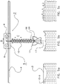
- Fig. 1 diagrammatically shows an assembly according to the invention.
- This comprises a feed gripping device according to the invention which is denoted overall by reference numeral 1.
- the feed gripping device 1 comprises a frame 2 with a grab bucket carrier which can be moved along the latter and which is denoted overall by reference numeral 3.
- Reference numeral 4 denotes a cross beam which can be displaced in the direction of the double arrow A by means of the longitudinal trolley 5 on wheels 6.
- Reference numeral 8 denotes a hoisting unit with transverse running wheels 9, and which can move in the direction of the double arrow B.
- the hoisting unit 8 comprises a hoisting cable 10 from which a grab bucket 11 hangs.
- reference numerals 12-1, 12-2 and 12-3 denote three piles of feed, with pile 12-1 being situated in a container 13.
- a first sensor 14 with a first image field 15 a laser height sensor 16 with a laser beam 17 and a second sensor 18 with a second image field 19.
- Reference numeral 20 denotes a gripper weighing sensor.
- a feed-collecting device 21-1 comprising a feed-collecting container 22 with a weighing sensor 23.
- Reference numeral 21-2 denotes an autonomously displaceable feed vehicle which also comprises a feed-collecting container 22 and a weighing sensor 23, and also a chassis 24 with drive wheels 25.
- a control unit is denoted by reference numeral 26.
- the illustrated feed gripping device 1 is, for example, arranged as an overhead crane wherein the grab bucket 11 is displaceable in three directions A, B and C. In this way, the grab bucket 11 can be placed above any desired pile of feed 12-1, 12-2 or 12-3, at an associated feed position, with any other number obviously also being possible. By lowering the grab bucket 11 into the pile of feed, the former can pick up feed. Then, the picked-up feed can be unloaded into one of the feed-collecting devices 21-1 or 21-2 by moving the grab bucket 11 there by means of the longitudinal trolley 5 and the transverse trolley 7 and opening the bucket. All this can take place under the control of the control unit 26 which, although it is shown here as a single unit, may also be provided in distributed form.
- the communication may in each case take place via cables or also by wireless means or similar.
- the control unit at least a part for the grab bucket thereof, on the grab bucket 11 or the grab bucket carrier 3 or to allow it to ride along with the grab bucket carrier when the latter is displaced.
- the grab bucket 11 or the control unit 26 can determine whether a useful amount of feed has been collected from the pile of feed. To this end, the measured amount of feed has to correspond, within certain margins, to the desired amount of feed. Should this not be the case, then the grab bucket 11 can drop the feed back onto the pile by opening up and then making a renewed attempt. If the amount of feed corresponds, within the predetermined margins, with the desired amount of feed, then this feed can be transferred to the feed-collecting device 21-1 or -2, as has already been stated. These preferably, but not necessarily, also contain a weighing sensor 23. This may serve to detect the amount of feed which has actually been collected, as it is possible that feed may have fallen from the grab bucket 11 during the displacement thereof.
- the gripper weighing sensor 20 may comprise, for example, a spring (scale), strain gauge or load cell.
- a weighing device may also be provided for example which measures a lifting torque or current for hoisting the filled grab bucket 11 in order to determine the total weight therefrom and consequently the weight of the amount of feed carried.
- a value of a parameter of at least one of the piles of feed 12-1 - 12-3 is determined. This may be achieved using one of the sensors 14, 16, 18.
- a height of the pile of feed may be determined using a laser height sensor 16 which is moved across the pile of feed using a laser beam 17 and thus determines a 1-dimensional height profile. This may be achieved by moving the grab bucket carrier 3 to which the laser height sensor 16 is attached in a direction A and/or B across the respective pile of feed. If desired, this may be repeated once or several times in order to obtain more information about the height profile of the pile of feed.
- a sensor which is attached to, for example, the longitudinal trolley 5.
- This comprises a similar laser height sensor or, for example, a 3D camera which has a first image field 15.
- a 3D camera By means of such a 3D camera, it is possible to obtain a 2-dimensional height profile of a pile of feed in one attempt.
- the first sensor 14 By displacing the grab bucket carrier 3 in the direction A, the first sensor 14 can be positioned above a desired pile of feed.
- This sensor may be slightly limited in the direction B, but is situated substantially out of reach of the piles of feed, and in particular of any dust or the like emanating therefrom.
- a second sensor 18 is provided, such as an ultrasound sensor, with a second image field 19.
- this is attached to the frame 2.
- this second sensor is limited in terms of flexibility in its range, but it does have the advantage that it does not have any moving parts, at least does not have to have any.
- said second sensor may, for example, be arranged to swivel so that it can still scan several different piles of feed.
- Fig. 2 shows an example of a 1-dimensional measured height profile.
- This profile comprises the height H as a function of the position X.
- This diagram may, for example, have been obtained by moving the respective sensor across the associated pile of feed and repeatedly determining the height.
- the term "the height" of the pile of feed may, for example, refer to the maximum height H 1 . It may also refer to the average height, for example, within reach of the grab bucket 11 at the location of the local position X 1 . This range is indicated by the double arrow W and the average height is determined as ⁇ H>.
- This average height may, for example, be determined by the control unit on the basis of the measured height profile or in any other known manner.
- Fig. 3 shows an example of a 2-dimensional measured height profile 30.
- This profile is composed of a number of profile lines 31. These profile lines may, for example, have been obtained by some parallel scans of a pile of feed, for example, in the manner from Fig. 2 . Alternatively, it is possible to obtain the profile 30 in one attempt using a 3D camera, ultrasound sensor or the like. It should be noted that the illustrated lines indicate that the pile of feed partly overhangs which is an indication of long-stemmed feed, such as hay. Maize or the like will not exhibit this overhang.
- Fig. 4 shows an example of a weight/grabbing height diagram.
- weight/grabbing height diagrams can be produced for one or more types of feed.
- the weight of the picked-up amount of feed is determined for a number of different grabbing heights.
- Such diagrams are, for example, (obviously) dependent on the intrinsic density of the feed, but also on, for example, the shape of the gripper, etc.
- grabbing height is in fact understood to mean the grabbing depth with respect to the (local) height of the pile of feed.
- the grabbing height ultimately indicates how far the feed gripping device has to dig into the pile of feed.
- a diagram I is shown for a first grab action from a still regular and compact pile of hay, such as a bale. Due to the compacting of the bale, diagram I already shows a relatively large weight for a relatively small height.
- Diagram II shows an identical diagram for a bale from which a few bites have already been taken. Due to these bites, in particular the top layer will have been pulled slightly apart, so that it has a lower density and so that maybe less material will hang from the gripper. Consequently, this diagram results in a lower weight at the same height as diagram I. Conversely, at the same desired weight G 1 , the diagram I will have a smaller height H 1 (that is to say the penetration depth below the (optionally local) height of the pile of feed) than diagram II. In the diagram, this is indicated by height H 1 and H 2 , respectively.
- diagrams I and II is nonlinear, which, for example, can be caused by different behaviour of the feed when hanging from the gripper, and certainly also by the shape of the gripper.
- diagram III shows a feed type in which the weight does depend linearly on the height, as is the case, for example, with a substantially square bucket and a fine-grained type of feed.
- this diagram is in fact a dynamic diagram.
- a grabbing height H is set for each new grabbing operation, associated with a desired amount of feed.
- the measured weight value associated with said grabbing height H can then be fed back as a new point of the weight/grabbing height function.
- Alternative ways of feeding back a measured couple of values (height, weight) is also possible according to any other known mathematical technique. The biggest advantage of this adjustment is of course the fact that the accuracy of grabbing a desired amount of feed can be significantly increased for new grabbing operations.
- Fig. 5a diagrammatically shows a pile of feed prior to the first grabbing operation and Figs. 5b and 5c show two diagrammatical examples of the pile of feed after the first grabbing operation. These examples serve to indicate how grabbing can change the character of the pile of feed.
- Fig. 5a shows a square bale of hay. The dotted line indicates which part of the bale of hay should be grabbed according to an associated weight/height diagram in order to pick up the desired amount of hay.
- the gripper 11 pulls an amount of hay from the bale, in which case however a relatively large amount of hay is pulled from the bale and still protrudes from the bottom of the bucket.
- the amount of hay which has been grabbed will have a much larger weight than intended.
- Fig. 5b the remaining pile of hay still has a density which is slightly similar to the initial density. However, this density may also be greatly reduced by grabbing operations, in particular if, on at least one occasion, a pile of hay has been too heavy, as a result of which it has been dumped again by the grab bucket.
- a (n diagrammatic) example thereof can be seen in Fig. 5c , where the pile of hay has a greater volume than the initial volume, even after the removal of an amount of hay therefrom. It will be clear that a different weight/grabbing height diagram will apply to the pile of hay which has been broken into than for the initial pile of hay. The invention is able to take this into account by dynamically adjusting the weight/grabbing height diagram by means of the current measurements.
Landscapes
- Life Sciences & Earth Sciences (AREA)
- Environmental Sciences (AREA)
- Birds (AREA)
- Animal Husbandry (AREA)
- Biodiversity & Conservation Biology (AREA)
- Control And Safety Of Cranes (AREA)
- Manipulator (AREA)
Applications Claiming Priority (2)
| Application Number | Priority Date | Filing Date | Title |
|---|---|---|---|
| NL2008675A NL2008675C2 (nl) | 2012-04-20 | 2012-04-20 | Voertuig voor het verplaatsen van voer. |
| PCT/NL2013/050178 WO2013157931A1 (en) | 2012-04-20 | 2013-03-14 | Vehicle for displacing feed |
Publications (3)
| Publication Number | Publication Date |
|---|---|
| EP2838355A1 EP2838355A1 (en) | 2015-02-25 |
| EP2838355B1 EP2838355B1 (en) | 2019-05-08 |
| EP2838355B2 true EP2838355B2 (en) | 2023-03-15 |
Family
ID=48044986
Family Applications (1)
| Application Number | Title | Priority Date | Filing Date |
|---|---|---|---|
| EP13713558.8A Active EP2838355B2 (en) | 2012-04-20 | 2013-03-14 | Feed gripping device |
Country Status (3)
| Country | Link |
|---|---|
| EP (1) | EP2838355B2 (nl) |
| NL (1) | NL2008675C2 (nl) |
| WO (1) | WO2013157931A1 (nl) |
Families Citing this family (9)
| Publication number | Priority date | Publication date | Assignee | Title |
|---|---|---|---|---|
| NL2011721C2 (nl) * | 2013-11-01 | 2015-05-04 | Lely Patent Nv | Werkwijze en inrichting voor het losmaken van diervoer. |
| NL2014096B1 (en) * | 2015-01-08 | 2016-09-30 | Lely Patent Nv | Feeding system and method for feeding non-human animals. |
| NL2014296B1 (nl) | 2015-02-13 | 2016-10-13 | Hendricus Liet Cornelis | Inrichting voor het losmaken van veevoer. |
| EP3566570B1 (de) * | 2018-05-09 | 2021-02-24 | Wasserbauer GmbH | Vorrichtung zur entnahme von futter |
| AT520924B1 (de) * | 2018-05-09 | 2019-09-15 | Wasserbauer Gmbh | Vorrichtung zur Entnahme von Futter aus einem Futterlager |
| NL2021276B1 (nl) * | 2018-07-10 | 2020-01-20 | Lely Patent Nv | Veevoermenginrichting met kalibratiefunctie |
| DE102018217029A1 (de) | 2018-10-04 | 2020-04-09 | Deere & Company | Verfahren zur Steuerung eines Ladewerkzeugs |
| NL2023390B1 (en) * | 2019-06-26 | 2021-02-01 | Lely Patent Nv | Method of feeding a group of animals at a feeding location and system for performing the method |
| CN113816270B (zh) * | 2021-09-18 | 2024-05-10 | 法兰泰克重工股份有限公司 | 一种抓斗清理窖池的控制方法 |
Family Cites Families (5)
| Publication number | Priority date | Publication date | Assignee | Title |
|---|---|---|---|---|
| DE3921871A1 (de) * | 1989-07-04 | 1991-01-17 | Anton Niederberger | Anlage zur automatischen verteilung von duerr- und gruenfutter auf die futterstellen in einem stall |
| NL1022678C2 (nl) * | 2003-02-14 | 2004-08-17 | Trioliet Mullos | Werkwijze en inrichting voor het uithalen van een hoeveelheid voer uit een voedervoorraad. |
| NL1033589C2 (nl) | 2007-03-26 | 2008-09-29 | Maasland Nv | Samenstel van een melkrobot met een melkrobotvoerplaats, en inrichting voor het grijpen en verplaatsen van materiaal. |
| JP2010138476A (ja) | 2008-12-15 | 2010-06-24 | Toshiba Corp | ジェットポンプビームおよびその製造方法 |
| NL2002644C2 (nl) * | 2009-03-19 | 2010-09-21 | Beheermij Schuitemaker B V | Inrichting en werkwijze voor het snijden van kuilvoer. |
-
2012
- 2012-04-20 NL NL2008675A patent/NL2008675C2/nl not_active IP Right Cessation
-
2013
- 2013-03-14 EP EP13713558.8A patent/EP2838355B2/en active Active
- 2013-03-14 WO PCT/NL2013/050178 patent/WO2013157931A1/en active Application Filing
Also Published As
| Publication number | Publication date |
|---|---|
| NL2008675C2 (nl) | 2013-10-23 |
| EP2838355A1 (en) | 2015-02-25 |
| EP2838355B1 (en) | 2019-05-08 |
| WO2013157931A1 (en) | 2013-10-24 |
Similar Documents
| Publication | Publication Date | Title |
|---|---|---|
| EP2838355B2 (en) | Feed gripping device | |
| EP2838356B1 (en) | Device for displacing livestock feed | |
| EP3401854A1 (en) | An agricultural system | |
| US10401867B2 (en) | Autonomous vehicle, in particular feed mixing vehicle, and method for controlling an autonomous vehicle | |
| US8539878B2 (en) | Square baler and a related control method | |
| US11740632B2 (en) | Agricultural system | |
| EP3043638B1 (en) | Livestock feed wagon | |
| AU2005227398B1 (en) | Method and apparatus for determining the loading of a bucket | |
| US8924097B2 (en) | Method and system for harvesting and ensilage of feed material | |
| EP2232982B1 (en) | Apparatus and method for cutting silage | |
| CA3191316A1 (en) | Automated grain filling system and related methods | |
| EP3062612B1 (en) | Method and device for loosening animal feed | |
| FI111836B (fi) | Menetelmä ja laitteisto dumpperin automaattiseksi kuormaamiseksi | |
| EP1516848A1 (en) | A device for gripping and displacing material, such as roughage for example | |
| ITBZ20090028A1 (it) | Sistema ed attrezzatura per l'automazione della raccolta in colture arboree | |
| CA3142703A1 (en) | System for mowing plants, in particular grass, and method of feeding animals by means of such a system | |
| EP4252514A1 (en) | Planter for planting seedlings and related method for contolling the operation of a planter | |
| CN110626244A (zh) | 作物卸料车辆以及相应用途 | |
| CA2575434A1 (en) | Method and device for position monitoring |
Legal Events
| Date | Code | Title | Description |
|---|---|---|---|
| PUAI | Public reference made under article 153(3) epc to a published international application that has entered the european phase |
Free format text: ORIGINAL CODE: 0009012 |
|
| 17P | Request for examination filed |
Effective date: 20141120 |
|
| AK | Designated contracting states |
Kind code of ref document: A1 Designated state(s): AL AT BE BG CH CY CZ DE DK EE ES FI FR GB GR HR HU IE IS IT LI LT LU LV MC MK MT NL NO PL PT RO RS SE SI SK SM TR |
|
| AX | Request for extension of the european patent |
Extension state: BA ME |
|
| DAX | Request for extension of the european patent (deleted) | ||
| TPAC | Observations filed by third parties |
Free format text: ORIGINAL CODE: EPIDOSNTIPA |
|
| RAP1 | Party data changed (applicant data changed or rights of an application transferred) |
Owner name: LELY PATENT N.V. |
|
| STAA | Information on the status of an ep patent application or granted ep patent |
Free format text: STATUS: EXAMINATION IS IN PROGRESS |
|
| 17Q | First examination report despatched |
Effective date: 20170724 |
|
| GRAP | Despatch of communication of intention to grant a patent |
Free format text: ORIGINAL CODE: EPIDOSNIGR1 |
|
| STAA | Information on the status of an ep patent application or granted ep patent |
Free format text: STATUS: GRANT OF PATENT IS INTENDED |
|
| INTG | Intention to grant announced |
Effective date: 20181018 |
|
| GRAS | Grant fee paid |
Free format text: ORIGINAL CODE: EPIDOSNIGR3 |
|
| GRAA | (expected) grant |
Free format text: ORIGINAL CODE: 0009210 |
|
| STAA | Information on the status of an ep patent application or granted ep patent |
Free format text: STATUS: THE PATENT HAS BEEN GRANTED |
|
| AK | Designated contracting states |
Kind code of ref document: B1 Designated state(s): AL AT BE BG CH CY CZ DE DK EE ES FI FR GB GR HR HU IE IS IT LI LT LU LV MC MK MT NL NO PL PT RO RS SE SI SK SM TR |
|
| REG | Reference to a national code |
Ref country code: GB Ref legal event code: FG4D |
|
| REG | Reference to a national code |
Ref country code: CH Ref legal event code: EP Ref country code: AT Ref legal event code: REF Ref document number: 1128724 Country of ref document: AT Kind code of ref document: T Effective date: 20190515 |
|
| REG | Reference to a national code |
Ref country code: DE Ref legal event code: R096 Ref document number: 602013054976 Country of ref document: DE Ref country code: IE Ref legal event code: FG4D |
|
| REG | Reference to a national code |
Ref country code: SE Ref legal event code: TRGR |
|
| REG | Reference to a national code |
Ref country code: NL Ref legal event code: FP |
|
| REG | Reference to a national code |
Ref country code: LT Ref legal event code: MG4D |
|
| PG25 | Lapsed in a contracting state [announced via postgrant information from national office to epo] |
Ref country code: ES Free format text: LAPSE BECAUSE OF FAILURE TO SUBMIT A TRANSLATION OF THE DESCRIPTION OR TO PAY THE FEE WITHIN THE PRESCRIBED TIME-LIMIT Effective date: 20190508 Ref country code: PT Free format text: LAPSE BECAUSE OF FAILURE TO SUBMIT A TRANSLATION OF THE DESCRIPTION OR TO PAY THE FEE WITHIN THE PRESCRIBED TIME-LIMIT Effective date: 20190908 Ref country code: HR Free format text: LAPSE BECAUSE OF FAILURE TO SUBMIT A TRANSLATION OF THE DESCRIPTION OR TO PAY THE FEE WITHIN THE PRESCRIBED TIME-LIMIT Effective date: 20190508 Ref country code: AL Free format text: LAPSE BECAUSE OF FAILURE TO SUBMIT A TRANSLATION OF THE DESCRIPTION OR TO PAY THE FEE WITHIN THE PRESCRIBED TIME-LIMIT Effective date: 20190508 Ref country code: NO Free format text: LAPSE BECAUSE OF FAILURE TO SUBMIT A TRANSLATION OF THE DESCRIPTION OR TO PAY THE FEE WITHIN THE PRESCRIBED TIME-LIMIT Effective date: 20190808 Ref country code: FI Free format text: LAPSE BECAUSE OF FAILURE TO SUBMIT A TRANSLATION OF THE DESCRIPTION OR TO PAY THE FEE WITHIN THE PRESCRIBED TIME-LIMIT Effective date: 20190508 Ref country code: LT Free format text: LAPSE BECAUSE OF FAILURE TO SUBMIT A TRANSLATION OF THE DESCRIPTION OR TO PAY THE FEE WITHIN THE PRESCRIBED TIME-LIMIT Effective date: 20190508 |
|
| PG25 | Lapsed in a contracting state [announced via postgrant information from national office to epo] |
Ref country code: LV Free format text: LAPSE BECAUSE OF FAILURE TO SUBMIT A TRANSLATION OF THE DESCRIPTION OR TO PAY THE FEE WITHIN THE PRESCRIBED TIME-LIMIT Effective date: 20190508 Ref country code: BG Free format text: LAPSE BECAUSE OF FAILURE TO SUBMIT A TRANSLATION OF THE DESCRIPTION OR TO PAY THE FEE WITHIN THE PRESCRIBED TIME-LIMIT Effective date: 20190808 Ref country code: RS Free format text: LAPSE BECAUSE OF FAILURE TO SUBMIT A TRANSLATION OF THE DESCRIPTION OR TO PAY THE FEE WITHIN THE PRESCRIBED TIME-LIMIT Effective date: 20190508 Ref country code: GR Free format text: LAPSE BECAUSE OF FAILURE TO SUBMIT A TRANSLATION OF THE DESCRIPTION OR TO PAY THE FEE WITHIN THE PRESCRIBED TIME-LIMIT Effective date: 20190809 |
|
| PG25 | Lapsed in a contracting state [announced via postgrant information from national office to epo] |
Ref country code: EE Free format text: LAPSE BECAUSE OF FAILURE TO SUBMIT A TRANSLATION OF THE DESCRIPTION OR TO PAY THE FEE WITHIN THE PRESCRIBED TIME-LIMIT Effective date: 20190508 Ref country code: DK Free format text: LAPSE BECAUSE OF FAILURE TO SUBMIT A TRANSLATION OF THE DESCRIPTION OR TO PAY THE FEE WITHIN THE PRESCRIBED TIME-LIMIT Effective date: 20190508 Ref country code: SK Free format text: LAPSE BECAUSE OF FAILURE TO SUBMIT A TRANSLATION OF THE DESCRIPTION OR TO PAY THE FEE WITHIN THE PRESCRIBED TIME-LIMIT Effective date: 20190508 Ref country code: RO Free format text: LAPSE BECAUSE OF FAILURE TO SUBMIT A TRANSLATION OF THE DESCRIPTION OR TO PAY THE FEE WITHIN THE PRESCRIBED TIME-LIMIT Effective date: 20190508 Ref country code: CZ Free format text: LAPSE BECAUSE OF FAILURE TO SUBMIT A TRANSLATION OF THE DESCRIPTION OR TO PAY THE FEE WITHIN THE PRESCRIBED TIME-LIMIT Effective date: 20190508 |
|
| REG | Reference to a national code |
Ref country code: DE Ref legal event code: R026 Ref document number: 602013054976 Country of ref document: DE |
|
| PLBI | Opposition filed |
Free format text: ORIGINAL CODE: 0009260 |
|
| PLAX | Notice of opposition and request to file observation + time limit sent |
Free format text: ORIGINAL CODE: EPIDOSNOBS2 |
|
| PG25 | Lapsed in a contracting state [announced via postgrant information from national office to epo] |
Ref country code: SM Free format text: LAPSE BECAUSE OF FAILURE TO SUBMIT A TRANSLATION OF THE DESCRIPTION OR TO PAY THE FEE WITHIN THE PRESCRIBED TIME-LIMIT Effective date: 20190508 |
|
| 26 | Opposition filed |
Opponent name: TRIOLIET B.V. Effective date: 20200207 |
|
| PG25 | Lapsed in a contracting state [announced via postgrant information from national office to epo] |
Ref country code: TR Free format text: LAPSE BECAUSE OF FAILURE TO SUBMIT A TRANSLATION OF THE DESCRIPTION OR TO PAY THE FEE WITHIN THE PRESCRIBED TIME-LIMIT Effective date: 20190508 |
|
| PG25 | Lapsed in a contracting state [announced via postgrant information from national office to epo] |
Ref country code: PL Free format text: LAPSE BECAUSE OF FAILURE TO SUBMIT A TRANSLATION OF THE DESCRIPTION OR TO PAY THE FEE WITHIN THE PRESCRIBED TIME-LIMIT Effective date: 20190508 |
|
| REG | Reference to a national code |
Ref country code: AT Ref legal event code: UEP Ref document number: 1128724 Country of ref document: AT Kind code of ref document: T Effective date: 20190508 |
|
| PG25 | Lapsed in a contracting state [announced via postgrant information from national office to epo] |
Ref country code: SI Free format text: LAPSE BECAUSE OF FAILURE TO SUBMIT A TRANSLATION OF THE DESCRIPTION OR TO PAY THE FEE WITHIN THE PRESCRIBED TIME-LIMIT Effective date: 20190508 |
|
| PLBB | Reply of patent proprietor to notice(s) of opposition received |
Free format text: ORIGINAL CODE: EPIDOSNOBS3 |
|
| PG25 | Lapsed in a contracting state [announced via postgrant information from national office to epo] |
Ref country code: MC Free format text: LAPSE BECAUSE OF FAILURE TO SUBMIT A TRANSLATION OF THE DESCRIPTION OR TO PAY THE FEE WITHIN THE PRESCRIBED TIME-LIMIT Effective date: 20190508 |
|
| REG | Reference to a national code |
Ref country code: CH Ref legal event code: PL |
|
| REG | Reference to a national code |
Ref country code: BE Ref legal event code: MM Effective date: 20200331 |
|
| PG25 | Lapsed in a contracting state [announced via postgrant information from national office to epo] |
Ref country code: LU Free format text: LAPSE BECAUSE OF NON-PAYMENT OF DUE FEES Effective date: 20200314 |
|
| PG25 | Lapsed in a contracting state [announced via postgrant information from national office to epo] |
Ref country code: LI Free format text: LAPSE BECAUSE OF NON-PAYMENT OF DUE FEES Effective date: 20200331 Ref country code: CH Free format text: LAPSE BECAUSE OF NON-PAYMENT OF DUE FEES Effective date: 20200331 |
|
| PG25 | Lapsed in a contracting state [announced via postgrant information from national office to epo] |
Ref country code: BE Free format text: LAPSE BECAUSE OF NON-PAYMENT OF DUE FEES Effective date: 20200331 |
|
| PGFP | Annual fee paid to national office [announced via postgrant information from national office to epo] |
Ref country code: IE Payment date: 20220328 Year of fee payment: 10 Ref country code: AT Payment date: 20220222 Year of fee payment: 10 |
|
| PG25 | Lapsed in a contracting state [announced via postgrant information from national office to epo] |
Ref country code: MT Free format text: LAPSE BECAUSE OF FAILURE TO SUBMIT A TRANSLATION OF THE DESCRIPTION OR TO PAY THE FEE WITHIN THE PRESCRIBED TIME-LIMIT Effective date: 20190508 Ref country code: CY Free format text: LAPSE BECAUSE OF FAILURE TO SUBMIT A TRANSLATION OF THE DESCRIPTION OR TO PAY THE FEE WITHIN THE PRESCRIBED TIME-LIMIT Effective date: 20190508 |
|
| PGFP | Annual fee paid to national office [announced via postgrant information from national office to epo] |
Ref country code: SE Payment date: 20220327 Year of fee payment: 10 Ref country code: IT Payment date: 20220322 Year of fee payment: 10 |
|
| PG25 | Lapsed in a contracting state [announced via postgrant information from national office to epo] |
Ref country code: MK Free format text: LAPSE BECAUSE OF FAILURE TO SUBMIT A TRANSLATION OF THE DESCRIPTION OR TO PAY THE FEE WITHIN THE PRESCRIBED TIME-LIMIT Effective date: 20190508 Ref country code: IS Free format text: LAPSE BECAUSE OF FAILURE TO SUBMIT A TRANSLATION OF THE DESCRIPTION OR TO PAY THE FEE WITHIN THE PRESCRIBED TIME-LIMIT Effective date: 20190908 |
|
| APBM | Appeal reference recorded |
Free format text: ORIGINAL CODE: EPIDOSNREFNO |
|
| APBP | Date of receipt of notice of appeal recorded |
Free format text: ORIGINAL CODE: EPIDOSNNOA2O |
|
| APAH | Appeal reference modified |
Free format text: ORIGINAL CODE: EPIDOSCREFNO |
|
| APBU | Appeal procedure closed |
Free format text: ORIGINAL CODE: EPIDOSNNOA9O |
|
| REG | Reference to a national code |
Ref country code: DE Ref legal event code: R084 Ref document number: 602013054976 Country of ref document: DE |
|
| PUAH | Patent maintained in amended form |
Free format text: ORIGINAL CODE: 0009272 |
|
| STAA | Information on the status of an ep patent application or granted ep patent |
Free format text: STATUS: PATENT MAINTAINED AS AMENDED |
|
| 27A | Patent maintained in amended form |
Effective date: 20230315 |
|
| AK | Designated contracting states |
Kind code of ref document: B2 Designated state(s): AL AT BE BG CH CY CZ DE DK EE ES FI FR GB GR HR HU IE IS IT LI LT LU LV MC MK MT NL NO PL PT RO RS SE SI SK SM TR |
|
| REG | Reference to a national code |
Ref country code: DE Ref legal event code: R102 Ref document number: 602013054976 Country of ref document: DE |
|
| REG | Reference to a national code |
Ref country code: NL Ref legal event code: FP |
|
| PGFP | Annual fee paid to national office [announced via postgrant information from national office to epo] |
Ref country code: FR Payment date: 20230327 Year of fee payment: 11 |
|
| REG | Reference to a national code |
Ref country code: GB Ref legal event code: 746 Effective date: 20230413 |
|
| P01 | Opt-out of the competence of the unified patent court (upc) registered |
Effective date: 20230505 |
|
| REG | Reference to a national code |
Ref country code: SE Ref legal event code: NAV Ref country code: AT Ref legal event code: MK05 Ref document number: 1128724 Country of ref document: AT Kind code of ref document: T Effective date: 20190508 |
|
| PG25 | Lapsed in a contracting state [announced via postgrant information from national office to epo] |
Ref country code: AT Free format text: LAPSE BECAUSE OF FAILURE TO SUBMIT A TRANSLATION OF THE DESCRIPTION OR TO PAY THE FEE WITHIN THE PRESCRIBED TIME-LIMIT Effective date: 20190508 |
|
| REG | Reference to a national code |
Ref country code: IE Ref legal event code: MM4A |
|
| PG25 | Lapsed in a contracting state [announced via postgrant information from national office to epo] |
Ref country code: IE Free format text: LAPSE BECAUSE OF NON-PAYMENT OF DUE FEES Effective date: 20230314 |
|
| PGFP | Annual fee paid to national office [announced via postgrant information from national office to epo] |
Ref country code: NL Payment date: 20240326 Year of fee payment: 12 |
|
| PG25 | Lapsed in a contracting state [announced via postgrant information from national office to epo] |
Ref country code: IT Free format text: LAPSE BECAUSE OF NON-PAYMENT OF DUE FEES Effective date: 20230314 |
|
| PGFP | Annual fee paid to national office [announced via postgrant information from national office to epo] |
Ref country code: DE Payment date: 20240327 Year of fee payment: 12 Ref country code: GB Payment date: 20240327 Year of fee payment: 12 |