EP2838330A2 - Electronic device - Google Patents
Electronic device Download PDFInfo
- Publication number
- EP2838330A2 EP2838330A2 EP14179772.0A EP14179772A EP2838330A2 EP 2838330 A2 EP2838330 A2 EP 2838330A2 EP 14179772 A EP14179772 A EP 14179772A EP 2838330 A2 EP2838330 A2 EP 2838330A2
- Authority
- EP
- European Patent Office
- Prior art keywords
- overlapping portion
- cooling
- cooling plate
- electronic device
- substrate
- Prior art date
- Legal status (The legal status is an assumption and is not a legal conclusion. Google has not performed a legal analysis and makes no representation as to the accuracy of the status listed.)
- Withdrawn
Links
Images



Classifications
-
- G—PHYSICS
- G06—COMPUTING OR CALCULATING; COUNTING
- G06F—ELECTRIC DIGITAL DATA PROCESSING
- G06F1/00—Details not covered by groups G06F3/00 - G06F13/00 and G06F21/00
- G06F1/16—Constructional details or arrangements
- G06F1/20—Cooling means
-
- H—ELECTRICITY
- H05—ELECTRIC TECHNIQUES NOT OTHERWISE PROVIDED FOR
- H05K—PRINTED CIRCUITS; CASINGS OR CONSTRUCTIONAL DETAILS OF ELECTRIC APPARATUS; MANUFACTURE OF ASSEMBLAGES OF ELECTRICAL COMPONENTS
- H05K7/00—Constructional details common to different types of electric apparatus
- H05K7/20—Modifications to facilitate cooling, ventilating, or heating
- H05K7/2039—Modifications to facilitate cooling, ventilating, or heating characterised by the heat transfer by conduction from the heat generating element to a dissipating body
-
- H—ELECTRICITY
- H05—ELECTRIC TECHNIQUES NOT OTHERWISE PROVIDED FOR
- H05K—PRINTED CIRCUITS; CASINGS OR CONSTRUCTIONAL DETAILS OF ELECTRIC APPARATUS; MANUFACTURE OF ASSEMBLAGES OF ELECTRICAL COMPONENTS
- H05K7/00—Constructional details common to different types of electric apparatus
- H05K7/20—Modifications to facilitate cooling, ventilating, or heating
- H05K7/20709—Modifications to facilitate cooling, ventilating, or heating for server racks or cabinets; for data centers, e.g. 19-inch computer racks
- H05K7/20763—Liquid cooling without phase change
- H05K7/20772—Liquid cooling without phase change within server blades for removing heat from heat source
Definitions
- Exemplary embodiments of the present disclosure relate to an electronic device required to be cooled.
- Patent Document 1 Japanese Laid-Open Patent Publication No. 2009-147382
- an object of the embodiments is to provide an electronic device which is improved in a mounting efficiency of a substrate.
- another object of the present disclosure is to achieve an acting effect which has not been achieved by a conventional technology, by configurations in exemplary embodiments to be described later.
- an electronic device comprising: a first cooling member including a first overlapping portion in which a first insertion hole is formed, and provided to be abutted on a component to be cooled provided on a substrate; a second cooling member including a second overlapping portion in which a second insertion hole is formed, and provided to be abutted on a component to be cooled provided on the substrate, the second overlapping portion overlapping the first overlapping portion; and a coupling member inserted through the first insertion hole and the second insertion hole to couple the first overlapping portion to the second overlapping portion through an elastic member.
- the first cooling member and the second cooling member coupled to each other through the coupling member are mounted on the substrate.
- the fixing regions on both sides of the substrate may be reduced, and the reduced regions may be a wiring region or a mounting region, thereby improving a mounting efficiency of the substrate.
- FIG. 1 is an explanatory view illustrating the electronic device 100 of the first exemplary embodiment.
- FIG. 2A is a plan view of a cooling device 10 provided in the electronic device 100 of the first exemplary embodiment
- FIG. 2B is a front view of the cooling device 10.
- FIGS. 3A to 3D are views illustrating four sides of a cooling plate 13 provided in the electronic device 100 of the first exemplary embodiment.
- FIG. 3A is a plan view
- FIG. 3B is a front view
- FIG. 3C is a right side view
- FIG. 3D is a left side view.
- the electronic device 100 of the first exemplary embodiment is an information processing device such as, for example, a server.
- the electronic device 100 includes many printed circuit boards 11 therein.
- another device may be targeted.
- respective components to be cooled that is, electronic components 12 which are heat-generating components required to be cooled are mounted on a substrate 11 to be adjacent to each other.
- the electronic components 12 required to be cooled include, for example, a large scale integrated circuit (LSI) for interconnect, and a central processing unit (CPU). Other components may be the electronic components 12 to be cooled.
- the cooling device 10 is mounted on the substrate 11.
- the cooling device 10 includes two cooling plates 13.
- the cooling device 10 includes a first cooling plate 13a corresponding to a first cooling member, and a second cooling plate 13b corresponding to a second cooling member. Both the first cooling plate 13a and the second cooling plate 13b are cooling plates 13, and have the same shape.
- the cooling plates 13 include coolant introducing/discharging outlets 14, and cool the electronic components 12 by circulating a coolant within the cooling plates 13. Any one of a coolant introducing pipe 15, a connecting pipe 16, and a coolant introducing/discharging pipe 17 is attached to each of the coolant introducing/discharging outlets 14 to circulate the coolant within each of the first cooling plate 13a and the second cooling plate 13b. Referring to FIGS. 3A and 3B , the cooling plates 13 will be described.
- Each cooling plate 13 includes a first overlapping portion 131 having first insertion holes 131a formed therein.
- the cooling plate 13 includes a second overlapping portion 132 having second insertion holes 132a formed therein.
- Each of the first insertion holes 131a and the second insertion holes 132a may be formed in a shape in which a coupling screw 18a to be described below may be inserted there through, or formed in a shape of a partially opened notch.
- the first overlapping portion 131 and the second overlapping portion 132 are formed as stepped portions which are engaged with each other. Specifically, the first overlapping portion 131 is formed as a stepped portion thinner than its peripheral portion so that the second overlapping portion 132 may be disposed below the first overlapping portion 131. The second overlapping portion 132 at one side is formed as a stepped portion thinner than its peripheral portion so that the first overlapping portion 131 may be disposed above the second overlapping portion 132. The second overlapping portion 132 is formed in a concave shape to accommodate an elastic member 20 to be described later. Since the first overlapping portion 131 and the second overlapping portion 132 are formed as stepped portions, the thickness of the first cooling plate 13a and the second cooling plate 13b which overlap each other may be reduced.
- the cooling plate 13 is prepared as each of the first cooling plate 13a and the second cooling plate 13b which is provided to be abutted on the electronic component 12 provided on the substrate 11.
- the first overlapping portion 131 and the second overlapping portion 132 overlap each other and are coupled to each other by coupling screws 18a and fixing nuts 18b through the elastic members 20.
- the coupling screws 18a and the fixing nuts 18b correspond to coupling members.
- the coupling screws 18a are inserted through the first insertion holes 131a, the second insertion holes 132a and third insertion holes 11a provided in the substrate 11 to tighten the fixing nuts 18b. That is, the coupling screws 18a are fixed to the substrate 11.
- the first overlapping portion 131 and the second overlapping portion 132 are fastened and coupled to each other in this manner, and thus the first cooling plate 13a and the second cooling plate 13b are integrated to be fixed to the substrate 11. Accordingly, the number of members to be used for fixing the first cooling plate 13a and the second cooling plate 13b to the substrate 11 may be reduced. That is, the fixing regions on both sides of the substrate 11 may be reduced by mounting the first cooling plate 13a and the second cooling plate 13b which are coupled to each other through the coupling screws 18a and the fixing nuts 18b, on the substrate 11. The regions corresponding to the reduced fixing regions may be used as a wiring region or a mounting region, thereby improving a mounting efficiency of the substrate 11.
- the cooling device 10 of the first exemplary embodiment since screwing is carried out at six locations, regions for two locations may be reduced. Further, the electronic components 12 may be disposed to be adjacent to each other, thereby improving the mounting density.
- an elastic member 20 is interposed between a head portion of each coupling screw 18a and the first overlapping portion 131. Such an elastic member 20 is also interposed between the first overlapping portion 131 and the second overlapping portion 132. These elastic members 20 enhance the flexibility of a posture of the first cooling plate 13a and the second cooling plate 13b.
- the electronic components 12 may be different from each other in height or surface smoothness. Angles of the top surfaces of the electronic components 12 with respect to the substrate surface may be varied. It is preferable that the cooling plates 13 are brought into close contact with the top surfaces of the electronic components 12 as much as possible to increase a cooling efficiency.
- the cooling device 10 includes the first cooling plate 13a and the second cooling plate 13b, and flexibly changes the posture of each of the first cooling plate 13a and the second cooling plate 13b so as to secure adhesion to the electronic components 12.
- the cooling device 10 includes fixing screws 19a and fixing nuts 19b configured to fix each of the first cooling plate 13a and the second cooling plate 13b to the substrate 11 through the elastic members 20.
- the fixing screws 19a are inserted through the elastic members 20, and inserted through the first insertion holes 131a or the second insertion holes 132a.
- the fixing screws 19a inserted through the first insertion holes 131a or the second insertion holes 132a are inserted through the third insertion holes 11a provided in the substrate 11.
- the fixing nuts 19b are fastened to the fixing screws 19a.
- the fixing screws 19a and the fixing nuts 19b correspond to fixing members.
- the posture of each of the first cooling plate 13a and the second cooling plate 13b may be flexibly varied by interposing the elastic members 20 therebetween. Accordingly, an adhesion of each of the first cooling plate 13a and the second cooling plate 13b to the electronic component 12 is increased, thereby improving the cooling efficiency.
- the cooling device 10 a part of the first cooling plate 13a and a part of the second cooling plate 13b overlap each other while the first cooling plate 13a and the second cooling plate 13b are coupled to each other by the coupling screws 18a and the fixing nuts 18b through the elastic members 20.
- Each of the first cooling plate 13a and the second cooling plate 13b is provided to be abutted on the electronic component 12 provided the substrate 11. Accordingly, the mounting efficiency of the substrate 11 may be improved, and a high cooling effect may be achieved.
- the cooling device 10 of the first exemplary embodiment uses the cooling plates 13 configured to circulate a coolant.
- a heat sink having heat dissipating fins may be employed.
- coil springs are employed as the elastic members.
- other conventionally known spring materials may be used.
- flexible cooling sheets may be disposed between the electronic components 12 and the cooling plates 13 in order to improve a thermal conductivity.
- FIG. 4A is a plan view of the cooling device 30 provided in an electronic device 100 of the second exemplary embodiment
- FIG. 4B is a front view of the cooling device 30.
- the cooling device 30 of the second exemplary embodiment is different from the cooling device 10 of the first exemplary embodiment in the following features. That is, the cooling device 10 includes two cooling plates 13 coupled to each other, while the cooling device 30 includes three cooling plates 13 coupled to each other in series. Specifically, the cooling device 30 includes a first cooling plate 13a, a second cooling plate 13b, and a third cooling plate 13c.
- the relationship between the second cooling plate 13b and the third cooling plate 13c corresponds to the relationship between the first cooling plate 13a and the second cooling plate 13b.
- the number of the cooling plates 13 coupled to each other in series may be increased.
- the number of members used for fixing each of the cooling plates 13 to the substrate 11 may be reduced because a first overlapping portion 131 and a second overlapping portion 132 are engaged with each other at an overlapping location of the first overlapping portion 131 and the second overlapping portion 132.
- the flexibility of posture of each cooling plate 13 is improved, the adhesion of the cooling plate 13 in relation to an electronic component 12 may be improved, and the cooling efficiency may also be improved.
- FIG. 5A is a plan view of the cooling device 50 provided in an electronic device 100 of the third exemplary embodiment
- FIG. 5B is a front view of the cooling device 50
- FIGS. 6A to 6D are views illustrating four sides of a cooling plate 53 provided in the electronic device of the third exemplary embodiment.
- FIG. 6A is a plan view
- FIG. 6B is a front view
- FIG. 6C is a right side view
- FIG. 6D is a left side view.
- the cooling plate 53 of the third exemplary embodiment includes a first overlapping portion 531 and a second overlapping portion 532 in the same manner as in the cooling plate 13 of the first exemplary embodiment.
- First insertion holes 531a are provided in the first overlapping portion 531
- second insertion holes 532a are provided in the second overlapping portion 532.
- Insertion holes 55 through which fixing screws 19a are inserted are additionally provided in the cooling plate 53.
- a first cooling plate 53a and a second cooling plate 53b are coupled through coupling screws 18a and fixing nuts 18b while a first overlapping portion 531 of the first cooling plate 53a and a second overlapping portion 532 of the second cooling plate 53b overlap each other.
- the first cooling plate 53a and the second cooling plate 53b coupled to each other by the coupling screws 18a and the fixing nuts 18b are fixed to a substrate 11 by the fixing screws 19a and the fixing nuts 19b at six locations.
- the coupling screws 18a are not inserted through third insertion holes 11a provided in the substrate 11. Accordingly, the region X indicated in FIG. 5B may be used as a wiring region or a component mounting region.
- the cooling device 50 of the third exemplary embodiment may improve the mounting efficiency of the substrate 11 in the same manner as the first exemplary embodiment.
- FIG. 7A is a plan view of the cooling device 70 provided in an electronic device 100 of the fourth exemplary embodiment
- FIG. 7B is a front view of the cooling device 70
- FIGS. 8A to 8D are views illustrating four sides of a cooling plate 73 provided in the electronic device 100 of the fourth exemplary embodiment.
- FIG. 8A is a plan view
- FIG. 8B is a front view
- FIG. 8C is a right side view
- FIG. 8D is a left side view.
- the cooling device 70 of the fourth exemplary embodiment includes four cooling plates 73 arranged in a square form, specifically, a first cooling plate 73a, a second cooling plate 73b, a third cooling plate 73c and a fourth cooling plate 73d.
- Each cooling plate 73 includes first overlapping portions 731 and second overlapping portions 732.
- First insertion holes 731a are provided in the first overlapping portions 731
- second insertion holes 732a are provided in the second overlapping portions 732.
- the first overlapping portions 731 are protruding portions which protrude laterally from the corresponding cooling plate 73 when the cooling plate 73 is seen from the top side, as illustrated in FIG. 8A .
- the first overlapping portions 731 are formed as protruding portions which protrude laterally from side edges of the rectangular cooling plate 73.
- the second overlapping portion 732 at one side is a recessed portion in which one of the first overlapping portions 731 as a protruding portion is fitted.
- the protruding portions are respectively provided at two sides of the rectangular cooling plate 73, and the recessed portions are respectively provided at the other two sides.
- the first cooling plate 73a and the second cooling plate 73b are coupled to each other by a coupling screw 18a and a fixing nut 18b at a position where side edges of the first cooling plate 73a and the second cooling plate 73b face each other while the first overlapping portion 731 and the second overlapping portion 732 overlap each other so that the protruding portion is fitted in the recessed portion.
- the second cooling plate 73b and the third cooling plate 73c, the third cooling plate 73c and the fourth cooling plate 73d, and the fourth cooling plate 73d and the first cooling plate 73a are coupled to each other in the same manner as in the first cooling plate 73a and the second cooling plate 73b.
- the cooling plates 73 are fixed to a substrate 11 by fixing screws 19a and fixing nuts 19b.
- each rectangular cooling plate 73 when four corners of each rectangular cooling plate 73 are screwed, sixteen screwing locations are required to fix four cooling plates 73 to the substrate 11.
- the cooling device 70 of the fourth exemplary embodiment since screwing is carried out at twelve locations, regions for four locations may be reduced. Further, electronic components 12 may be disposed to be adjacent to each other, thereby improving the mounting density.
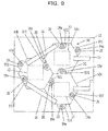
- FIG. 9 is a plan view of a cooling device 90 provided in an electronic device 100 of the fifth exemplary embodiment.
- FIGS. 10A to 10D are views illustrating four sides of a cooling plate 93 provided in the electronic device 100 of the fifth exemplary embodiment.
- FIG. 10A is a plan view
- FIG. 10B is a front view
- FIG. 10C is a right side view
- FIG. 10D is a left side view.
- the cooling device 90 of the fifth exemplary embodiment includes three cooling plates 93 arranged in a triangle form, specifically, a first cooling plate 93a, a second cooling plate 93b and a third cooling plate 93c.
- Each cooling plate 93 is formed in a hexagonal shape, and includes two first overlapping portions 931 and two second overlapping portions 932.
- First insertion holes 931a are provided in the first overlapping portions 931
- second insertion holes 932a are provided in the second overlapping portions 932.
- the first overlapping portions 931 are protruding portions which protrude laterally from the cooling plate 93 when the cooling plate 93 is seen from the top side, as illustrated in FIG. 10A .
- each first overlapping portion 931 is formed as a protruding portion which protrudes laterally from the corresponding side edge of the hexagonal cooling plate 93.
- the second overlapping portion 932 at one side is a recessed portion in which the first overlapping portion 931 as a protruding portion is fitted.
- the protruding portions are respectively provided at two sides of the hexagonal cooling plate 93, and the recessed portions are respectively provided at other two sides.
- the first cooling plate 93a and the second cooling plate 93b are coupled to each other by a coupling screw 18a and a fixing nut 18b at a position where side edges of the first cooling plate 93a and the second cooling plate 93b face each other while the first overlapping portion 931 and the second overlapping portion 932 overlap each other.
- the second cooling plate 93b and the third cooling plate 93c, and the third cooling plate 93c and the first cooling plate 93a are coupled to each other in the same manner as in the first cooling plate 93a and the second cooling plate 93b.
- the cooling plates 93 are fixed to a substrate 11 by fixing screws 19a and fixing nuts 19b.
- regions used for screwing may also be reduced as compared to a case where each cooling plate is individually screwed. Further, since electronic components 12 may be disposed to be adjacent to each other, the mounting density is improved.
Landscapes
- Engineering & Computer Science (AREA)
- Physics & Mathematics (AREA)
- General Engineering & Computer Science (AREA)
- Thermal Sciences (AREA)
- Microelectronics & Electronic Packaging (AREA)
- Theoretical Computer Science (AREA)
- Computer Hardware Design (AREA)
- Human Computer Interaction (AREA)
- General Physics & Mathematics (AREA)
- Cooling Or The Like Of Electrical Apparatus (AREA)
- Cooling Or The Like Of Semiconductors Or Solid State Devices (AREA)
Abstract
Description
- Exemplary embodiments of the present disclosure relate to an electronic device required to be cooled.
- In various electronic devices such as, for example, an electronic computer or an information processing device, high-density mounting has recently been progressed. In this background, a plurality of high heat-generating electronic components may be mounted on a substrate. A heating amount itself of electronic components tends to be increased, and a heating density on the substrate has been increased. In order to cool such an electronic device, various kinds of cooling devices have been suggested. For example, there is known a technology of improving the mounting efficiency of the electronic components and the cooling devices (see, e.g., Patent Document 1).
- [Patent Document 1] Japanese Laid-Open Patent Publication No.
2009-147382 - However, there is room for further improvement of conventional electronic devices, including an electronic device disclosed in Japanese Laid-Open Patent Publication No.
2009-147382 - Therefore, an object of the embodiments is to provide an electronic device which is improved in a mounting efficiency of a substrate. Besides this object, another object of the present disclosure is to achieve an acting effect which has not been achieved by a conventional technology, by configurations in exemplary embodiments to be described later.
- According to the present disclosure, there is provided an electronic device comprising: a first cooling member including a first overlapping portion in which a first insertion hole is formed, and provided to be abutted on a component to be cooled provided on a substrate; a second cooling member including a second overlapping portion in which a second insertion hole is formed, and provided to be abutted on a component to be cooled provided on the substrate, the second overlapping portion overlapping the first overlapping portion; and a coupling member inserted through the first insertion hole and the second insertion hole to couple the first overlapping portion to the second overlapping portion through an elastic member.
- The first cooling member and the second cooling member coupled to each other through the coupling member are mounted on the substrate.
- Thus, the fixing regions on both sides of the substrate may be reduced, and the reduced regions may be a wiring region or a mounting region, thereby improving a mounting efficiency of the substrate.
-
-
FIG. 1 is an explanatory view illustrating an electronic device of a first exemplary embodiment. -
FIG. 2A is a plan view of a cooling device provided in the electronic device of the first exemplary embodiment, andFIG. 2B is a front view of the cooling device. -
FIGS. 3A to 3D are views illustrating four sides of a cooling plate provided in the electronic device of the first exemplary embodiment.FIG. 3A is a plan view,FIG. 3B is a front view,FIG. 3C is a right side view, andFIG. 3D is a left side view. -
FIG. 4A is a plan view of a cooling device provided in an electronic device of a second exemplary embodiment, andFIG. 4B is a front view of the cooling device. -
FIG. 5A is a plan view of a cooling device provided in an electronic device of a third exemplary embodiment, andFIG. 5B is a front view of the cooling device. -
FIGS. 6A to 6D are views illustrating four sides of a cooling plate provided in the electronic device of the third exemplary embodiment.FIG. 6A is a plan view,FIG. 6B is a front view,FIG. 6C is a right side view, andFIG. 6D is a left side view. -
FIG. 7A is a plan view of a cooling device provided in an electronic device of a fourth exemplary embodiment, andFIG. 7B is a front view of the cooling device. -
FIGS. 8A to 8D are views illustrating four sides of a cooling plate provided in the electronic device of the fourth exemplary embodiment.FIG. 8A is a plan view,FIG. 8B is a front view,FIG. 8C is a right side view, andFIG. 8D is a left side view. -
FIG. 9 is a plan view of a cooling device provided in an electronic device of a fifth exemplary embodiment. -
FIGS. 10A to 10D are views illustrating four sides of a cooling plate provided in the electronic device of the fifth exemplary embodiment.FIG. 10A is a plan view,FIG. 10B is a front view,FIG. 10C is a right side view, andFIG. 10D is a left side view. - Hereinafter, exemplary embodiments of the present disclosure will be described with reference to accompanying drawings. In the drawings, for example, the size and the ratio of each illustrated part may not completely correspond to those of a real part. Further, in some drawings, for the convenience of description, actually existing elements may be omitted, or some elements may be illustrated in an exaggerated size as compared to an actual size.
- First, an electronic device 100 of a first exemplary embodiment will be described with reference to
FIGS. 1 to 3 .FIG. 1 is an explanatory view illustrating the electronic device 100 of the first exemplary embodiment.FIG. 2A is a plan view of acooling device 10 provided in the electronic device 100 of the first exemplary embodiment, andFIG. 2B is a front view of thecooling device 10.FIGS. 3A to 3D are views illustrating four sides of acooling plate 13 provided in the electronic device 100 of the first exemplary embodiment.FIG. 3A is a plan view,FIG. 3B is a front view,FIG. 3C is a right side view, andFIG. 3D is a left side view. - Referring to
FIG. 1 , the electronic device 100 of the first exemplary embodiment is an information processing device such as, for example, a server. The electronic device 100 includes many printedcircuit boards 11 therein. As an electronic device, another device may be targeted. Referring toFIGS. 2A and 2B , respective components to be cooled, that is,electronic components 12 which are heat-generating components required to be cooled are mounted on asubstrate 11 to be adjacent to each other. Theelectronic components 12 required to be cooled include, for example, a large scale integrated circuit (LSI) for interconnect, and a central processing unit (CPU). Other components may be theelectronic components 12 to be cooled. Thecooling device 10 is mounted on thesubstrate 11. Thecooling device 10 includes two coolingplates 13. Specifically, thecooling device 10 includes afirst cooling plate 13a corresponding to a first cooling member, and asecond cooling plate 13b corresponding to a second cooling member. Both thefirst cooling plate 13a and thesecond cooling plate 13b are coolingplates 13, and have the same shape. The coolingplates 13 include coolant introducing/dischargingoutlets 14, and cool theelectronic components 12 by circulating a coolant within the coolingplates 13. Any one of acoolant introducing pipe 15, a connectingpipe 16, and a coolant introducing/dischargingpipe 17 is attached to each of the coolant introducing/dischargingoutlets 14 to circulate the coolant within each of thefirst cooling plate 13a and thesecond cooling plate 13b. Referring toFIGS. 3A and 3B , the coolingplates 13 will be described. - Each cooling
plate 13 includes a first overlappingportion 131 havingfirst insertion holes 131a formed therein. The coolingplate 13 includes a second overlappingportion 132 havingsecond insertion holes 132a formed therein. Each of thefirst insertion holes 131a and thesecond insertion holes 132a may be formed in a shape in which acoupling screw 18a to be described below may be inserted there through, or formed in a shape of a partially opened notch. - The first overlapping
portion 131 and the second overlappingportion 132 are formed as stepped portions which are engaged with each other. Specifically, the first overlappingportion 131 is formed as a stepped portion thinner than its peripheral portion so that the second overlappingportion 132 may be disposed below the first overlappingportion 131. The second overlappingportion 132 at one side is formed as a stepped portion thinner than its peripheral portion so that the first overlappingportion 131 may be disposed above the second overlappingportion 132. The second overlappingportion 132 is formed in a concave shape to accommodate anelastic member 20 to be described later. Since the first overlappingportion 131 and the second overlappingportion 132 are formed as stepped portions, the thickness of thefirst cooling plate 13a and thesecond cooling plate 13b which overlap each other may be reduced. - The cooling
plate 13 is prepared as each of thefirst cooling plate 13a and thesecond cooling plate 13b which is provided to be abutted on theelectronic component 12 provided on thesubstrate 11. The first overlappingportion 131 and the second overlappingportion 132 overlap each other and are coupled to each other by couplingscrews 18a and fixing nuts 18b through theelastic members 20. Here, the coupling screws 18a and the fixing nuts 18b correspond to coupling members. The coupling screws 18a are inserted through thefirst insertion holes 131a, thesecond insertion holes 132a andthird insertion holes 11a provided in thesubstrate 11 to tighten the fixing nuts 18b. That is, the coupling screws 18a are fixed to thesubstrate 11. The first overlappingportion 131 and the second overlappingportion 132 are fastened and coupled to each other in this manner, and thus thefirst cooling plate 13a and thesecond cooling plate 13b are integrated to be fixed to thesubstrate 11. Accordingly, the number of members to be used for fixing thefirst cooling plate 13a and thesecond cooling plate 13b to thesubstrate 11 may be reduced. That is, the fixing regions on both sides of thesubstrate 11 may be reduced by mounting thefirst cooling plate 13a and thesecond cooling plate 13b which are coupled to each other through the coupling screws 18a and the fixing nuts 18b, on thesubstrate 11. The regions corresponding to the reduced fixing regions may be used as a wiring region or a mounting region, thereby improving a mounting efficiency of thesubstrate 11. For example, when four corners of therectangular cooling plate 13 are screwed, eight screwing locations are required to fix two coolingplates 13 to thesubstrate 11. In contrast, in thecooling device 10 of the first exemplary embodiment, since screwing is carried out at six locations, regions for two locations may be reduced. Further, theelectronic components 12 may be disposed to be adjacent to each other, thereby improving the mounting density. - Referring to
FIGS. 2A and 2B , anelastic member 20 is interposed between a head portion of eachcoupling screw 18a and the first overlappingportion 131. Such anelastic member 20 is also interposed between the first overlappingportion 131 and the second overlappingportion 132. Theseelastic members 20 enhance the flexibility of a posture of thefirst cooling plate 13a and thesecond cooling plate 13b. Theelectronic components 12 may be different from each other in height or surface smoothness. Angles of the top surfaces of theelectronic components 12 with respect to the substrate surface may be varied. It is preferable that the coolingplates 13 are brought into close contact with the top surfaces of theelectronic components 12 as much as possible to increase a cooling efficiency. Thecooling device 10 includes thefirst cooling plate 13a and thesecond cooling plate 13b, and flexibly changes the posture of each of thefirst cooling plate 13a and thesecond cooling plate 13b so as to secure adhesion to theelectronic components 12. - The
cooling device 10 includes fixingscrews 19a and fixing nuts 19b configured to fix each of thefirst cooling plate 13a and thesecond cooling plate 13b to thesubstrate 11 through theelastic members 20. The fixing screws 19a are inserted through theelastic members 20, and inserted through thefirst insertion holes 131a or thesecond insertion holes 132a. The fixing screws 19a inserted through thefirst insertion holes 131a or thesecond insertion holes 132a are inserted through thethird insertion holes 11a provided in thesubstrate 11. The fixing nuts 19b are fastened to the fixingscrews 19a. The fixing screws 19a and the fixing nuts 19b correspond to fixing members. The posture of each of thefirst cooling plate 13a and thesecond cooling plate 13b may be flexibly varied by interposing theelastic members 20 therebetween. Accordingly, an adhesion of each of thefirst cooling plate 13a and thesecond cooling plate 13b to theelectronic component 12 is increased, thereby improving the cooling efficiency. - In this manner, in the
cooling device 10, a part of thefirst cooling plate 13a and a part of thesecond cooling plate 13b overlap each other while thefirst cooling plate 13a and thesecond cooling plate 13b are coupled to each other by the coupling screws 18a and the fixing nuts 18b through theelastic members 20. Each of thefirst cooling plate 13a and thesecond cooling plate 13b is provided to be abutted on theelectronic component 12 provided thesubstrate 11. Accordingly, the mounting efficiency of thesubstrate 11 may be improved, and a high cooling effect may be achieved. - The
cooling device 10 of the first exemplary embodiment uses thecooling plates 13 configured to circulate a coolant. However, instead of the coolingplates 13, a heat sink having heat dissipating fins may be employed. In the first exemplary embodiment, coil springs are employed as the elastic members. However, instead of the coil springs, other conventionally known spring materials may be used. Although omitted in the first exemplary embodiment, flexible cooling sheets may be disposed between theelectronic components 12 and thecooling plates 13 in order to improve a thermal conductivity. - A cooling
device 30 of a second exemplary embodiment will be described with reference toFIGS. 4A and 4B. FIG. 4A is a plan view of thecooling device 30 provided in an electronic device 100 of the second exemplary embodiment, andFIG. 4B is a front view of thecooling device 30. Thecooling device 30 of the second exemplary embodiment is different from the coolingdevice 10 of the first exemplary embodiment in the following features. That is, thecooling device 10 includes two coolingplates 13 coupled to each other, while thecooling device 30 includes three coolingplates 13 coupled to each other in series. Specifically, thecooling device 30 includes afirst cooling plate 13a, asecond cooling plate 13b, and athird cooling plate 13c. In thecooling device 30, the relationship between thesecond cooling plate 13b and thethird cooling plate 13c corresponds to the relationship between thefirst cooling plate 13a and thesecond cooling plate 13b. In this manner, the number of the coolingplates 13 coupled to each other in series may be increased. Even when the number of the coolingplates 13 is increased, the number of members used for fixing each of the coolingplates 13 to thesubstrate 11 may be reduced because a first overlappingportion 131 and a second overlappingportion 132 are engaged with each other at an overlapping location of the first overlappingportion 131 and the second overlappingportion 132. Also, since the flexibility of posture of each coolingplate 13 is improved, the adhesion of the coolingplate 13 in relation to anelectronic component 12 may be improved, and the cooling efficiency may also be improved. - Some elements which are common to those in the first exemplary embodiment are given the same reference numerals in drawings, and detailed descriptions thereof will be omitted. Such handling in the description of the second exemplary embodiment will be the same in descriptions of respective following exemplary embodiments.
- A cooling
device 50 of a third exemplary embodiment will be described with reference toFIGS. 5A to 6D .FIG. 5A is a plan view of thecooling device 50 provided in an electronic device 100 of the third exemplary embodiment, andFIG. 5B is a front view of thecooling device 50.FIGS. 6A to 6D are views illustrating four sides of acooling plate 53 provided in the electronic device of the third exemplary embodiment.FIG. 6A is a plan view,FIG. 6B is a front view,FIG. 6C is a right side view, andFIG. 6D is a left side view. - The cooling
plate 53 of the third exemplary embodiment includes a first overlappingportion 531 and a second overlappingportion 532 in the same manner as in thecooling plate 13 of the first exemplary embodiment.First insertion holes 531a are provided in the first overlappingportion 531, andsecond insertion holes 532a are provided in the second overlappingportion 532. Insertion holes 55 through which fixing screws 19a are inserted are additionally provided in thecooling plate 53. Referring toFIGS. 5A and 5B , afirst cooling plate 53a and asecond cooling plate 53b are coupled throughcoupling screws 18a and fixing nuts 18b while a first overlappingportion 531 of thefirst cooling plate 53a and a second overlappingportion 532 of thesecond cooling plate 53b overlap each other. Thefirst cooling plate 53a and thesecond cooling plate 53b coupled to each other by the coupling screws 18a and the fixing nuts 18b are fixed to asubstrate 11 by the fixingscrews 19a and the fixing nuts 19b at six locations. Unlike in the first exemplary embodiment, the coupling screws 18a are not inserted throughthird insertion holes 11a provided in thesubstrate 11. Accordingly, the region X indicated inFIG. 5B may be used as a wiring region or a component mounting region. In this manner, thecooling device 50 of the third exemplary embodiment may improve the mounting efficiency of thesubstrate 11 in the same manner as the first exemplary embodiment. - A cooling
device 70 of a fourth exemplary embodiment will be described with reference toFIGS. 7A to 8D .FIG. 7A is a plan view of thecooling device 70 provided in an electronic device 100 of the fourth exemplary embodiment, andFIG. 7B is a front view of thecooling device 70.FIGS. 8A to 8D are views illustrating four sides of acooling plate 73 provided in the electronic device 100 of the fourth exemplary embodiment.FIG. 8A is a plan view,FIG. 8B is a front view,FIG. 8C is a right side view, andFIG. 8D is a left side view. - The
cooling device 70 of the fourth exemplary embodiment includes four coolingplates 73 arranged in a square form, specifically, afirst cooling plate 73a, asecond cooling plate 73b, athird cooling plate 73c and afourth cooling plate 73d. Each coolingplate 73 includes first overlappingportions 731 and second overlappingportions 732.First insertion holes 731a are provided in the first overlappingportions 731, andsecond insertion holes 732a are provided in the second overlappingportions 732. The first overlappingportions 731 are protruding portions which protrude laterally from the corresponding coolingplate 73 when the coolingplate 73 is seen from the top side, as illustrated inFIG. 8A . Specifically, the first overlappingportions 731 are formed as protruding portions which protrude laterally from side edges of therectangular cooling plate 73. The second overlappingportion 732 at one side is a recessed portion in which one of the first overlappingportions 731 as a protruding portion is fitted. The protruding portions are respectively provided at two sides of therectangular cooling plate 73, and the recessed portions are respectively provided at the other two sides. Thefirst cooling plate 73a and thesecond cooling plate 73b are coupled to each other by acoupling screw 18a and a fixingnut 18b at a position where side edges of thefirst cooling plate 73a and thesecond cooling plate 73b face each other while the first overlappingportion 731 and the second overlappingportion 732 overlap each other so that the protruding portion is fitted in the recessed portion. Thesecond cooling plate 73b and thethird cooling plate 73c, thethird cooling plate 73c and thefourth cooling plate 73d, and thefourth cooling plate 73d and thefirst cooling plate 73a are coupled to each other in the same manner as in thefirst cooling plate 73a and thesecond cooling plate 73b. At other locations, the coolingplates 73 are fixed to asubstrate 11 by fixingscrews 19a and fixing nuts 19b. - For example, when four corners of each
rectangular cooling plate 73 are screwed, sixteen screwing locations are required to fix fourcooling plates 73 to thesubstrate 11. In contrast, in thecooling device 70 of the fourth exemplary embodiment, since screwing is carried out at twelve locations, regions for four locations may be reduced. Further,electronic components 12 may be disposed to be adjacent to each other, thereby improving the mounting density. - Hereinafter, a
cooling device 90 of a fifth exemplary embodiment will be described with reference toFIGS. 9 to 10D .FIG. 9 is a plan view of acooling device 90 provided in an electronic device 100 of the fifth exemplary embodiment.FIGS. 10A to 10D are views illustrating four sides of acooling plate 93 provided in the electronic device 100 of the fifth exemplary embodiment.FIG. 10A is a plan view,FIG. 10B is a front view,FIG. 10C is a right side view, andFIG. 10D is a left side view. - The
cooling device 90 of the fifth exemplary embodiment includes three coolingplates 93 arranged in a triangle form, specifically, afirst cooling plate 93a, asecond cooling plate 93b and athird cooling plate 93c. Each coolingplate 93 is formed in a hexagonal shape, and includes two first overlappingportions 931 and two second overlappingportions 932.First insertion holes 931a are provided in the first overlappingportions 931, andsecond insertion holes 932a are provided in the second overlappingportions 932. Here, the first overlappingportions 931 are protruding portions which protrude laterally from the coolingplate 93 when the coolingplate 93 is seen from the top side, as illustrated inFIG. 10A . Specifically, each first overlappingportion 931 is formed as a protruding portion which protrudes laterally from the corresponding side edge of thehexagonal cooling plate 93. The second overlappingportion 932 at one side is a recessed portion in which the first overlappingportion 931 as a protruding portion is fitted. The protruding portions are respectively provided at two sides of thehexagonal cooling plate 93, and the recessed portions are respectively provided at other two sides. Thefirst cooling plate 93a and thesecond cooling plate 93b are coupled to each other by acoupling screw 18a and a fixingnut 18b at a position where side edges of thefirst cooling plate 93a and thesecond cooling plate 93b face each other while the first overlappingportion 931 and the second overlappingportion 932 overlap each other. Thesecond cooling plate 93b and thethird cooling plate 93c, and thethird cooling plate 93c and thefirst cooling plate 93a are coupled to each other in the same manner as in thefirst cooling plate 93a and thesecond cooling plate 93b. At other locations, the coolingplates 93 are fixed to asubstrate 11 by fixingscrews 19a and fixing nuts 19b. - With this arrangement, regions used for screwing may also be reduced as compared to a case where each cooling plate is individually screwed. Further, since
electronic components 12 may be disposed to be adjacent to each other, the mounting density is improved. - Preferred exemplary embodiments of the present disclosure have been described in detail, but the present disclosure is not limited to the specific exemplary embodiments. Various modification and changes may be made within the scope of the present disclosure described in the appended claims.
Claims (7)
- An electronic device comprising:a first cooling member including a first overlapping portion in which a first insertion hole is formed, and provided to be abutted on a first component to be cooled provided on a substrate;a second cooling member including a second overlapping portion in which a second insertion hole is formed, and provided to be abutted on a second component to be cooled provided on the substrate, the second overlapping portion overlapping the first overlapping portion; anda coupling member inserted through the first insertion hole and the second insertion hole to couple the first overlapping portion to the second overlapping portion through an elastic member.
- The electronic device according to claim 1, wherein the coupling member is fixed to the substrate through a third insertion hole provided in the substrate.
- The electronic device according to claim 1 or 2, wherein the first overlapping portion and the second overlapping portion include stepped portions, respectively, which are engaged with each other.
- The electronic device according to claim 1 or 2, wherein the first overlapping portion is a protruding portion which protrudes laterally from the first cooling member when the first cooling member is seen from a top side, and the second overlapping portion is a recessed portion in which the protruding portion is fitted.
- The electronic device according to any one of claims 1 through 4, wherein an elastic member is disposed between the first overlapping portion and the second overlapping portion.
- The electronic device according to claim 1, further comprising a fixing member configured to fix the first cooling member or the second cooling member to the substrate through an elastic member.
- The electronic device according to any one of claims 1 through 6, wherein the first cooling member and the second cooling member are formed in a substantially same polygonal plate shape having a plurality of sides, each of the first cooling member and the second cooling member being provided with the first overlapping portion at a first side, and the second overlapping portion at a second side facing the first side.
Applications Claiming Priority (1)
| Application Number | Priority Date | Filing Date | Title |
|---|---|---|---|
| JP2013168982A JP6201511B2 (en) | 2013-08-15 | 2013-08-15 | Electronics |
Publications (2)
| Publication Number | Publication Date |
|---|---|
| EP2838330A2 true EP2838330A2 (en) | 2015-02-18 |
| EP2838330A3 EP2838330A3 (en) | 2016-06-01 |
Family
ID=51298564
Family Applications (1)
| Application Number | Title | Priority Date | Filing Date |
|---|---|---|---|
| EP14179772.0A Withdrawn EP2838330A3 (en) | 2013-08-15 | 2014-08-04 | Electronic device |
Country Status (3)
| Country | Link |
|---|---|
| US (1) | US9600039B2 (en) |
| EP (1) | EP2838330A3 (en) |
| JP (1) | JP6201511B2 (en) |
Cited By (1)
| Publication number | Priority date | Publication date | Assignee | Title |
|---|---|---|---|---|
| EP3872601A3 (en) * | 2020-02-27 | 2021-11-03 | Giga-Byte Technology Co., Ltd. | Heat dissipation device |
Families Citing this family (3)
| Publication number | Priority date | Publication date | Assignee | Title |
|---|---|---|---|---|
| CN113316349B (en) * | 2020-02-27 | 2024-05-24 | 技嘉科技股份有限公司 | Heat dissipation device |
| GB2586094B (en) * | 2020-06-22 | 2022-06-15 | Zhong Qingchang | Rackless thermal-efficient modular power electronic system |
| US11749923B2 (en) | 2021-04-15 | 2023-09-05 | Te Connectivity Solutions Gmbh | Cooling system for socket connector |
Citations (1)
| Publication number | Priority date | Publication date | Assignee | Title |
|---|---|---|---|---|
| JP2009147382A (en) | 2009-03-25 | 2009-07-02 | Toshiba Corp | Electronics |
Family Cites Families (10)
| Publication number | Priority date | Publication date | Assignee | Title |
|---|---|---|---|---|
| JP4089098B2 (en) * | 1999-08-18 | 2008-05-21 | 横河電機株式会社 | Printed circuit board cooling structure |
| US6490161B1 (en) * | 2002-01-08 | 2002-12-03 | International Business Machines Corporation | Peripheral land grid array package with improved thermal performance |
| JP4387777B2 (en) * | 2003-11-28 | 2009-12-24 | 株式会社東芝 | Electronics |
| JP4675666B2 (en) * | 2005-04-15 | 2011-04-27 | 株式会社東芝 | Electronics |
| JP2008251687A (en) * | 2007-03-29 | 2008-10-16 | Toshiba Corp | Printed circuit board and electronic device equipped with the same |
| TWI337837B (en) * | 2007-06-08 | 2011-02-21 | Ama Precision Inc | Heat sink and modular heat sink |
| US7626822B2 (en) * | 2007-12-12 | 2009-12-01 | Fu Zhun Precision Industry (Shen Zhen) Co., Ltd. | Heat sink assembly for multiple electronic components |
| US7667970B2 (en) * | 2007-12-27 | 2010-02-23 | Fu Zhun Precision Industry (Shen Zhen) Co., Ltd. | Heat sink assembly for multiple electronic components |
| JP2010263045A (en) * | 2009-05-01 | 2010-11-18 | Fuzhun Precision Industry (Shenzhen) Co Ltd | Heat dissipation equipment |
| JP2010263118A (en) * | 2009-05-08 | 2010-11-18 | Fuzhun Precision Industry (Shenzhen) Co Ltd | Heat dissipation device |
-
2013
- 2013-08-15 JP JP2013168982A patent/JP6201511B2/en active Active
-
2014
- 2014-08-04 EP EP14179772.0A patent/EP2838330A3/en not_active Withdrawn
- 2014-08-11 US US14/456,155 patent/US9600039B2/en active Active
Patent Citations (1)
| Publication number | Priority date | Publication date | Assignee | Title |
|---|---|---|---|---|
| JP2009147382A (en) | 2009-03-25 | 2009-07-02 | Toshiba Corp | Electronics |
Cited By (2)
| Publication number | Priority date | Publication date | Assignee | Title |
|---|---|---|---|---|
| EP3872601A3 (en) * | 2020-02-27 | 2021-11-03 | Giga-Byte Technology Co., Ltd. | Heat dissipation device |
| US11612050B2 (en) | 2020-02-27 | 2023-03-21 | Giga-Byte Technology Co., Ltd. | Heat dissipation device |
Also Published As
| Publication number | Publication date |
|---|---|
| EP2838330A3 (en) | 2016-06-01 |
| US9600039B2 (en) | 2017-03-21 |
| US20150049430A1 (en) | 2015-02-19 |
| JP6201511B2 (en) | 2017-09-27 |
| JP2015037161A (en) | 2015-02-23 |
Similar Documents
| Publication | Publication Date | Title |
|---|---|---|
| US9313923B2 (en) | Multi-component heatsink with self-adjusting pin fins | |
| US20060250772A1 (en) | Liquid DIMM Cooler | |
| US8120917B2 (en) | Heat dissipation device | |
| CN109727937B (en) | Assemblies including heat dissipating elements and related systems and methods | |
| US20090219687A1 (en) | Memory heat-dissipating mechanism | |
| US9836098B2 (en) | Method and system for attachment of a heat sink to a circuit board | |
| EP2838330A2 (en) | Electronic device | |
| CA2756902C (en) | Wedge lock for use with a single board computer and method of assembling a computer system | |
| US20120000625A1 (en) | Heat dissipation device | |
| JP5670447B2 (en) | Electronics | |
| US20080266806A1 (en) | Electronic assembly that includes a heat sink which cools multiple electronic components | |
| US10672683B2 (en) | Heat transfer adapter plate | |
| CN1942063A (en) | Non-metallic grid coverings for metal enclosures | |
| CN103813693A (en) | Heat dissipating device combination | |
| US8300403B2 (en) | Computer system and heat sink | |
| CN113316349B (en) | Heat dissipation device | |
| JP2016131218A (en) | Heat dissipation device | |
| CN101896052A (en) | Cooling module | |
| CN205376499U (en) | Radiator | |
| US20100220440A1 (en) | Heat sink and motherboard assembly utilizing the heat sink | |
| JP2009164615A (en) | Memory heat dissipation structure | |
| US20120300408A1 (en) | Heat-dissipation device and elecrtonic device thereon | |
| TWI498078B (en) | Heat conductive plate and heat dissipating module including the heat conductive plate | |
| CN102866750A (en) | Storage heat dissipation device | |
| TWM369493U (en) | Heat dissipation device |
Legal Events
| Date | Code | Title | Description |
|---|---|---|---|
| 17P | Request for examination filed |
Effective date: 20140804 |
|
| AK | Designated contracting states |
Kind code of ref document: A2 Designated state(s): AL AT BE BG CH CY CZ DE DK EE ES FI FR GB GR HR HU IE IS IT LI LT LU LV MC MK MT NL NO PL PT RO RS SE SI SK SM TR |
|
| AX | Request for extension of the european patent |
Extension state: BA ME |
|
| PUAI | Public reference made under article 153(3) epc to a published international application that has entered the european phase |
Free format text: ORIGINAL CODE: 0009012 |
|
| PUAL | Search report despatched |
Free format text: ORIGINAL CODE: 0009013 |
|
| AK | Designated contracting states |
Kind code of ref document: A3 Designated state(s): AL AT BE BG CH CY CZ DE DK EE ES FI FR GB GR HR HU IE IS IT LI LT LU LV MC MK MT NL NO PL PT RO RS SE SI SK SM TR |
|
| AX | Request for extension of the european patent |
Extension state: BA ME |
|
| RIC1 | Information provided on ipc code assigned before grant |
Ipc: H05K 7/20 20060101AFI20160426BHEP |
|
| R17P | Request for examination filed (corrected) |
Effective date: 20160630 |
|
| RBV | Designated contracting states (corrected) |
Designated state(s): AL AT BE BG CH CY CZ DE DK EE ES FI FR GB GR HR HU IE IS IT LI LT LU LV MC MK MT NL NO PL PT RO RS SE SI SK SM TR |
|
| STAA | Information on the status of an ep patent application or granted ep patent |
Free format text: STATUS: THE APPLICATION HAS BEEN WITHDRAWN |
|
| 18W | Application withdrawn |
Effective date: 20171102 |