JP4675666B2 - Electronics - Google Patents
Electronics Download PDFInfo
- Publication number
- JP4675666B2 JP4675666B2 JP2005118641A JP2005118641A JP4675666B2 JP 4675666 B2 JP4675666 B2 JP 4675666B2 JP 2005118641 A JP2005118641 A JP 2005118641A JP 2005118641 A JP2005118641 A JP 2005118641A JP 4675666 B2 JP4675666 B2 JP 4675666B2
- Authority
- JP
- Japan
- Prior art keywords
- housing
- circuit board
- fan
- air
- heating element
- Prior art date
- Legal status (The legal status is an assumption and is not a legal conclusion. Google has not performed a legal analysis and makes no representation as to the accuracy of the status listed.)
- Active
Links
Images


Classifications
-
- G—PHYSICS
- G06—COMPUTING; CALCULATING OR COUNTING
- G06F—ELECTRIC DIGITAL DATA PROCESSING
- G06F1/00—Details not covered by groups G06F3/00 - G06F13/00 and G06F21/00
- G06F1/16—Constructional details or arrangements
- G06F1/20—Cooling means
- G06F1/203—Cooling means for portable computers, e.g. for laptops
Description
本発明は、例えばCPUのような発熱体を有する電子機器に係り、特にファンを用いて発熱体を冷却するための構造に関する。 The present invention relates to an electronic device having a heating element such as a CPU, and more particularly to a structure for cooling a heating element using a fan.
CPUは、例えばポータブルコンピュータのような電子機器に組み込まれている。CPUが動作する際に発する熱は、処理速度の高速化や多機能化に伴い増加している。CPUの温度が高くなり過ぎると、CPUの効率的な動作が失われたり、動作不能に陥るといった問題が生じてくる。 The CPU is incorporated in an electronic device such as a portable computer. The heat generated when the CPU operates increases as the processing speed increases and the number of functions increases. If the temperature of the CPU becomes too high, there arises a problem that the efficient operation of the CPU is lost or the CPU becomes inoperable.
CPUの放熱性能を高めるため、従来の電子機器はCPUを強制的に冷却する空冷式の冷却装置を搭載している。冷却装置は、CPUに熱的に接続されたヒートシンクと、ヒートシンクに冷却風を送風するファンとを備えている。 In order to improve the heat dissipation performance of the CPU, conventional electronic devices are equipped with an air-cooling type cooling device that forcibly cools the CPU. The cooling device includes a heat sink that is thermally connected to the CPU and a fan that blows cooling air to the heat sink.
ヒートシンクおよびファンは、一つのモジュールとして一体化されているとともに、電子機器の筐体の内部に収められている。ヒートシンクは、CPUの熱を受ける受熱面、放熱フィンおよび冷却風通路を有する偏平な箱状であり、例えばアルミニウム合金のような熱伝導性に優れた金属材料で造られている。放熱フィンは冷却風通路に露出している。冷却風通路は、筐体の内部から仕切られており、この冷却風通路の下流端が筐体の側壁又は後壁に開口する排気口に連なっている。 The heat sink and the fan are integrated as a single module and are housed in the casing of the electronic device. The heat sink has a flat box shape having a heat receiving surface that receives heat from the CPU, a heat radiating fin, and a cooling air passage, and is made of a metal material having excellent thermal conductivity such as an aluminum alloy. The radiating fin is exposed to the cooling air passage. The cooling air passage is partitioned from the inside of the housing, and the downstream end of the cooling air passage is connected to an exhaust port that opens to the side wall or the rear wall of the housing.
ファンは、ファンケースと羽根車とを備えている。ファンケースは、吸込口および吐出口を有している。羽根車は、ファンケースに収容されている。羽根車は、吸込口から空気を吸い込むとともに、この吸い込んだ空気を吐出口から冷却風通路に送風する。このため、ファンから送られる空気は冷却風となって冷却風通路を流れ、この流れの過程でCPUの熱を受けるヒートシンクを冷却する。ヒートシンクでの熱交換により暖められた冷却風は、冷却風通路の下流端から排気口を通じて筐体の外に排出される。 The fan includes a fan case and an impeller. The fan case has a suction port and a discharge port. The impeller is housed in a fan case. The impeller sucks air from the suction port and blows the sucked air from the discharge port to the cooling air passage. For this reason, the air sent from the fan becomes cooling air and flows through the cooling air passage, and cools the heat sink that receives the heat of the CPU in the process of this flow. The cooling air heated by heat exchange at the heat sink is discharged from the downstream end of the cooling air passage to the outside of the casing through the exhaust port.
さらに、従来の冷却装置では、ファンケースの上面と筐体との間に空気導入路が形成されている。空気導入路は、筐体の吸気口とファンケースの吸込口との間を接続するためのものである。空気導入路は、スポンジのようなシール材によって筐体の内部と仕切られている。シール材は、ファンケースと筐体との間に介在されている(例えば、特許文献1参照)。
特許文献1に開示された冷却装置では、CPUの熱を受けるヒートシンクに冷却風通路が形成されているとともに、このヒートシンクにファンが一体的に組み込まれている。このような構成によると、ファンとは別に専用のヒートシンクが必要となり、部品点数が多くなるのを避けられない。この結果、電子機器のコストが高くなる。 In the cooling device disclosed in Patent Document 1, a cooling air passage is formed in a heat sink that receives heat from the CPU, and a fan is integrally incorporated in the heat sink. According to such a configuration, a dedicated heat sink is necessary in addition to the fan, and it is inevitable that the number of parts increases. As a result, the cost of the electronic device increases.
さらに、ヒートシンクとファンとが一体化されているので、冷却装置そのものが重く大きなものとなるとともに、筐体の内部に冷却装置を収容する広いスペースを確保しなくてはならない。したがって、電子機器を軽量化したり筐体をコンパクト化する上での妨げとなるといった不具合がある。 Furthermore, since the heat sink and the fan are integrated, the cooling device itself must be heavy and large, and a wide space for housing the cooling device must be secured inside the housing. Therefore, there is a problem that it becomes an obstacle to reducing the weight of the electronic device or downsizing the housing.
本発明の目的は、発熱体を効率よく冷却しつつ、発熱体を冷却するために必要な部品点数を削減してコストを低減できるとともに、軽量でコンパクトな電子機器を得ることにある。 An object of the present invention is to obtain a lightweight and compact electronic device while reducing the number of parts required for cooling the heating element while efficiently cooling the heating element, thereby reducing the cost.
上記目的を達成するため、本発明の一つの形態に係る電子機器は、
吸気口が設けられた底壁を有する筐体と、
上記筐体の内部に収容された回路板と、
上記回路板の下面に実装されて、上記吸気口の上に位置された発熱体と、
上記回路板の下面に実装され、上記発熱体の周囲に位置された回路部品と、
上記筐体に収容され、上記筐体内の空気を吸い込んで吐き出すファンと、を備えている。
弾性変形が可能なシール材が上記回路板と上記底壁との間に介在されている。シール材は、上記発熱体を取り囲むとともに上記回路部品の上を横切るように上記回路板の下面に貼り付けられ、上記回路板および上記底壁と協働して上記筐体の内部に上記発熱体から上記ファンに至る導風路を構成したことを特徴としている。
In order to achieve the above object, an electronic apparatus according to one aspect of the present invention provides:
A housing having a bottom wall provided with an air inlet;
A circuit board housed inside the housing;
A heating element mounted on the lower surface of the circuit board and positioned on the inlet;
Circuit components mounted on the lower surface of the circuit board and positioned around the heating element;
A fan housed in the housing and sucking and discharging the air in the housing.
A sealing material capable of elastic deformation is interposed between the circuit board and the bottom wall . A sealing material is attached to the lower surface of the circuit board so as to surround the heating element and cross over the circuit component, and cooperates with the circuit board and the bottom wall to form the heating element inside the casing. It is characterized in that an air guide path extending from to the fan is configured .
本発明によれば、簡単な構造で発熱体を効率よく冷却できる。しかも、発熱体を冷却するために必要な部品点数を削減してコストを低減できるとともに、軽量でコンパクトな電子機器を提供できる。 According to the present invention, the heating element can be efficiently cooled with a simple structure. In addition, it is possible to reduce the number of parts required for cooling the heating element to reduce costs, and to provide a lightweight and compact electronic device.
以下本発明の実施の形態をポータブルコンピュータに適用した図面に基づいて説明する。 Embodiments of the present invention will be described below with reference to the drawings applied to a portable computer.
図1および図2は、電子機器の一例であるポータブルコンピュータ1を開示している。ポータブルコンピュータ1は、本体ユニット2と表示ユニット3とを備えている。本体ユニット2は、第1の筐体4を有している。第1の筐体4は、例えばマグネシウム合金のような金属材料で造られている。第1の筐体4は、上壁4a、底壁4b、左右の側壁4c、4d、前壁4eおよび後壁4fを有する偏平な箱状をなしている。
1 and 2 disclose a portable computer 1 which is an example of an electronic apparatus. The portable computer 1 includes a
第1の筐体4は、ベース5とトップカバー6とで構成されている。ベース5は、底壁4bを有するとともに、バッテリパック7を取り外し可能に支持している。バッテリパック7は、ベース5の前半部に位置している。
The first housing 4 includes a base 5 and a
底壁4bは、複数の吸気口8を有している。吸気口8は、バッテリパック7の後方に位置するとともに、第1の筐体4の幅方向に間隔を存して並んでいる。吸気口8は、第1の筐体4の内部に開口している。
The
トップカバー6は、上壁4aを有するとともに、キーボード9を支持している。キーボード9は、上壁4aの後半部に位置している。左側の側壁4cは、複数の排気口10とカードスロット11とを有している。排気口10およびカードスロット11は、第1の筐体4の奥行き方向に並んでいる。排気口10は、側壁4cの後端に位置している。
The
表示ユニット3は、第2の筐体12と液晶表示パネル13とを備えている。液晶表示パネル13は、第2の筐体12に収容されている。液晶表示パネル13は、画像を表示するスクリーン13aを有している。スクリーン13aは、第2の筐体12の前面に形成した開口部14を通じて第2の筐体12の外方に露出している。
The
第2の筐体12は、第1の筐体4の後端部にヒンジを介して支持されている。そのため、表示ユニット3は、キーボード9を上方から覆うように本体ユニット2の上に横たわる閉じ位置と、キーボード9やスクリーン13aを露出させるように起立する開き位置との間で回動可能となっている。
The
図3ないし図5に示すように、第1の筐体4はプリント回路板16を収容している。プリント回路板16は、トップカバー6に支持されて上壁4aおよびキーボード9の下方に位置している。プリント回路板16は、ベース5の底壁4bと向かい合う下面16aを有している。
As shown in FIGS. 3 to 5, the first housing 4 accommodates a printed
プリント回路板16の下面16aにCPU17、ゲートアレイ18、ICチップのような複数の回路部品19およびカードホルダ20が実装されている。CPU17およびゲートアレイ18は、発熱体の一例であり、上記吸気口8の真上に位置するように第1の筐体4の幅方向に並んでいる。言い換えると、CPU17およびゲートアレイ18は、第1の筐体4の内部において吸気口8と対向し合うような位置関係に保たれている。
A
図5に概略的に示すように、CPU17は、ベース基板21とICチップ22とを有している。ベース基板21は、プリント回路板16の下面16aに半田付けされている。ICチップ22は、ベース基板21の下面の中央部に位置するとともに、処理速度の高速化や多機能化に伴って動作中の発熱量が非常に大きなものとなっている。
As schematically shown in FIG. 5, the
CPU17のICチップ22およびゲートアレイ18に夫々熱拡散板23が熱的に接続されている。熱拡散板23は、例えば銅のような熱伝導性に優れた金属材料にて構成され、CPU17およびゲートアレイ18を下方から覆うような四角い板状をなしている。
A
各熱拡散板23は、一対の支持突起23a,23bを有している。支持突起23a,23bは、例えば熱拡散板23にバーリング加工を施すことにより形成され、熱拡散板23から下向きに突出している。
Each
各熱拡散板23に取付金具24が保持されている。取付金具24は、例えばステンレス鋼板によって造られている。取付金具24は、金具本体25と一対の脚部26a,26bとを有している。金具本体25は、熱拡散熱23の対角線に沿うような姿勢で熱拡散板23の下面に重ね合わされている。熱拡散板23から突出する支持突起24a,24bは、金具本体25を貫通しており、この支持突起24a,24bの先端をかしめることで、金具本体25が熱拡散板23に一体的に保持されている。
A mounting
一方の脚部26aは、金具本体25の一端に位置している。他方の脚部26bは、金具本体25の他端に位置している。脚部26a,26bは、金具本体25に対し略直角に折り曲げられているとともに、金具本体25からプリント回路板16に向けて延びている。脚部26a,26bの先端は、プリント回路板16にねじ27を介して固定されている。そのため、熱拡散板23は、取付金具24を介してプリント回路板16に保持されている。
One
熱拡散熱23に保持された取付金具24は、夫々ばね性を有している。一方の取付金具24は、一方の熱拡散板23をCPU17のICチップ22に押し付けている。このICチップ22と一方の熱拡散板23との間には、熱伝導性を有するグリース28が介在されている。他方の取付金具24は、他方の熱拡散板23をゲートアレイ18に押し付けている。
Each of the mounting
この結果、CPU17のICチップ22に熱的に接続された一方の熱拡散板23およびゲートアレイ18に熱的に接続された他方の熱拡散板23は、底壁4bの吸気口8の真上に位置するとともに、これら吸気口8に面している。
As a result, one
上記回路部品19は、上記CPU17やゲートアレイ18の周囲に位置している。カードホルダ20は、例えばSDカードのようなカード状記憶媒体を取り外し可能に支持するためのものであり、上記第1の筐体4のカードスロット11と向かい合っている。回路部品19およびカードホルダ20は、プリント回路板16の下面16aから張り出している。
The
図3ないし図5に示すように、第1の筐体4の内部に遠心ファン30が収容されている。遠心ファン30は、第1の筐体4の左側の側壁4cと後壁4fとで規定される角部に位置し、上記CPU17やゲートアレイ18に隣接している。
As shown in FIGS. 3 to 5, a
遠心ファン30は、偏平なファンケース31と羽根車32とを備えている。ファンケース31は、トップカバー6の上壁4aに支持されている。このファンケース31は、第1および第2の吸込口33a,33bと吐出口34とを有している。第1の吸込口33aは、ファンケース31の下面に形成されているとともに、第2の吸込口33bは、ファンケース31の上面に形成されている。吐出口34は、ファンケース31の外周面に形成されて、第1の筐体4の排気口10に連なっている。
The
羽根車32は、ファンケース31に収容されて、第1および第2の吸込口33a,33bの間に同軸状に位置している。羽根車32は、モータ35を介してファンケース31に支持されている。モータ35は、CPU17又はゲートアレイ18の温度が予め決められた値に達した時に動作する。モータ35からのトルクを受けて羽根車32が回転すると、第1の筐体4の内部の空気が第1および第2の吸込口33a,33bを通じて羽根車32の回転中心部に吸い込まれる。この吸い込まれた空気は、羽根車32の外周からファンケース31の内部に放出されるとともに、吐出口34から排気口10に向けて吐き出される。
The
図3ないし図5に示すように、第1の筐体4の底壁4aとプリント回路板16の下面16aとの間にシール材36が介在されている。シール材36は、例えば弾性変形が可能なスポンジあるいは気泡性を有する柔軟なゴム材料にて構成され、四角い断面形状を有する角柱状をなしている。
As shown in FIGS. 3 to 5, a sealing
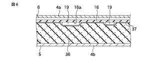
シール材36は、上記CPU17およびゲートアレイ18を取り囲むようにプリント回路板16の下面16aに両面接着テープ37を介して貼り付けられている。図6に示すように、両面接着テープ37は、シール材36を貼り付ける位置に回路部品19やカードホルダ20が存在する場合に、これら回路部品19やカードホルダ20の上に直接貼り付けられている。このため、シール材36は回路部品19およびカードホルダ20の上を横切っている。
The sealing
シール材36は、第1の端部36aと第2の端部36bとを有している。第1および第2の端部36a,36bは、第1の筐体4の幅方向に離れているとともに、遠心ファン30のファンケース31に接している。
The sealing
さらに、シール材36のうち両面接着テープ37とは反対側の面は、第1の筐体4の底壁4bに押し付けられている。したがって、シール材36は、底壁4bとプリント回路板16との間で第1の筐体4の厚み方向に圧縮されており、底壁4bおよびプリント回路板16に密に接している。
Further, the surface of the sealing
シール材36は、底壁4bおよびプリント回路板16と協働して第1の筐体4の内部に導風路38を形成している。導風路38は、CPU17およびゲートアレイ18から遠心ファン30に至るように、第1の筐体4の内部と仕切られている。
The sealing
そのため、CPU17およびゲートアレイ18と対向する吸気口8は、導風路38の上流端に位置するとともに、遠心ファン30の第1および第2の吸込口33a,33bは、導風路38の下流端に開口している。
Therefore, the
このような構成において、CPU17およびゲートアレイ18は、ポータブルコンピュータ1の使用中に発熱する。CPU17およびゲートアレイ18が発する熱は、夫々熱拡散板23に伝わり、各熱拡散板23の隅々にまで均一に拡散する。よって、CPU17およびゲートアレイ18の熱の多くは、熱拡散板23を通じて導風路38内に放出される。
In such a configuration, the
遠心ファン30のモータ35は、CPU17およびゲートアレイ18の温度が予め決められた値に達した時に動作する。遠心ファン30の羽根車32が回転すると、第1の筐体4の吸気口8に負圧が作用し、第1の筐体4の外の空気が吸気口8から導風路38に吸い込まれる。
The
CPU17やゲートアレイ18の熱を受ける熱拡散板23は、吸気口8の真上に位置している。このため、吸気口8から導風路38に吸い込まれた空気は、図5に矢印で示すように熱拡散板23に直接吹き付けられ、この熱拡散板23の下面に沿うようにして流れる。これにより、熱拡散板23が満遍なく冷やされるとともに、熱拡散板23との熱交換により暖められた空気が導風路38内を遠心ファン30に向けて流れる。
The
導風路38内の空気は、ファンケース31の吸込口33a,33bから羽根車32の回転中心部に吸い込まれる。この吸い込まれた空気は、羽根車32の外周からファンケース31内に吐き出されるとともに、吐出口34から排気口10を経て第1の筐体4の外に排出される。
Air in the
このようなポータブルコンピュータ1によれば、遠心ファン30が動作した時に、吸気口8から導風路38に吸い込まれる空気をCPU17やゲートアレイ18の熱を受ける熱拡散板23に直に吹き付けることができる。このため、熱拡散板23を介してCPU17やゲートアレイ18を効率よく冷却できるとともに、熱移送用の格別なヒートパイプを不要とすることができる。
According to such a portable computer 1, when the
しかも、CPU17やゲートアレイ18から導風路38に放出された輻射熱を、導風路38を流れる空気によって第1の筐体4の外に排出することができる。このため、第1の筐体4の内部にCPU17やゲートアレイ18からの輻射熱が滞留し難くなり、第1の筐体4の内部の温度上昇を防止することができる。
In addition, the radiant heat released from the
加えて、上記構成によると、熱拡散板23を冷却した空気を遠心ファン30に導く導風路38は、スポンジ製のシール材36でCPU17やゲートアレイ18を取り囲むことにより構成される。言い換えると、第1の筐体4の底壁4bおよびプリント回路板16が導風路38を定める構成要素を兼用するので、従来のような導風路を有する専用のヒートシンクが不要となる。
In addition, according to the above configuration, the
このため、ヒートパイプが不要なことと合わせて、CPU17やゲートアレイ18を冷却するために必要な部品点数を削減することができる。したがって、簡単な構成でCPU17やゲートアレイ18を効率よく冷却することができる。よって、ポータブルコンピュータ1のコストを低減できるとともに、ポータブルコンピュータ1の軽量化やコンパクト化を実現できる。
For this reason, the number of parts required for cooling the
さらに、シール材36は、両面接着テープ37を介してプリント回路板16の下面16aに貼り付ければよいので、導風路38の形状を自由に設定できる。そのため、冷却を要する発熱部品の数が増えたり、遠心ファン30の位置が変更となった場合でも容易に対応することができ、第1の筐体4の大幅な設計変更が不要となる。
Furthermore, since the sealing
本発明は、上記実施の形態に限らず、発明の主旨を逸脱しない範囲内で種々変更して実施可能である。 The present invention is not limited to the above-described embodiment, and various modifications can be made without departing from the spirit of the invention.
例えば発熱体は、CPUやゲートアレイに限らず、チップセットでもよいし、吸気口と向かい合う発熱体の数も上記実施の形態に制約されない。 For example, the heating element is not limited to the CPU and the gate array, but may be a chip set, and the number of heating elements facing the intake port is not limited to the above embodiment.
さらに、本発明に係る電子機器は、ポータブルコンピュータに限らず、表示ユニットを持たない携帯形情報端末(Personal Digital Assistant)であっても同様に実施可能である。 Furthermore, the electronic device according to the present invention is not limited to a portable computer, and can be implemented in the same manner even if it is a portable information terminal (Personal Digital Assistant) having no display unit.
4…筐体(第1の筐体)、4b…底壁、8…吸気口、16…回路板(プリント回路板)、16a…下面、17,18…発熱体(CPU、ゲートアレイ)、19…回路部品、30…ファン(遠心ファン)、36…シール材、38…導風路。 DESCRIPTION OF SYMBOLS 4 ... Housing | casing (1st housing | casing), 4b ... Bottom wall, 8 ... Air inlet, 16 ... Circuit board (printed circuit board), 16a ... Lower surface, 17, 18 ... Heating body (CPU, gate array), 19 ... circuit components, 30 ... fan (centrifugal fan), 36 ... sealing material, 38 ... air guide path.
Claims (6)
上記筐体の内部に収容された回路板と、
上記回路板の下面に実装されて、上記吸気口の上に位置された発熱体と、
上記回路板の下面に実装され、上記発熱体の周囲に位置された回路部品と、
上記筐体に収容され、上記筐体内の空気を吸い込んで吐き出すファンと、
上記発熱体を取り囲むとともに上記回路部品の上を横切るように上記回路板の下面に貼り付けられ、上記回路板と上記底壁との間に介在されて、上記回路板および上記底壁と協働して上記筐体の内部に上記発熱体から上記ファンに至る導風路を構成した弾性変形が可能なシール材と、を具備したことを特徴とする電子機器。 A housing having a bottom wall provided with an air inlet;
A circuit board housed inside the housing;
A heating element mounted on the lower surface of the circuit board and positioned on the inlet;
Circuit components mounted on the lower surface of the circuit board and positioned around the heating element;
A fan that is housed in the housing and sucks and exhales air in the housing;
Surrounds the heating element attached to the lower surface of the circuit board so as to cross over the circuit component, is interposed between the circuit board and the bottom wall, said circuit board and said bottom wall cooperating And an elastically deformable sealing material that constitutes an air guide path from the heating element to the fan inside the housing.
Priority Applications (3)
| Application Number | Priority Date | Filing Date | Title |
|---|---|---|---|
| JP2005118641A JP4675666B2 (en) | 2005-04-15 | 2005-04-15 | Electronics |
| US11/392,347 US7310227B2 (en) | 2005-04-15 | 2006-03-29 | Electronic apparatus |
| CNB2006100747922A CN100377036C (en) | 2005-04-15 | 2006-04-14 | Electronic apparatus |
Applications Claiming Priority (1)
| Application Number | Priority Date | Filing Date | Title |
|---|---|---|---|
| JP2005118641A JP4675666B2 (en) | 2005-04-15 | 2005-04-15 | Electronics |
Related Child Applications (1)
| Application Number | Title | Priority Date | Filing Date |
|---|---|---|---|
| JP2010275677A Division JP5197725B2 (en) | 2010-12-10 | 2010-12-10 | Electronics |
Publications (3)
| Publication Number | Publication Date |
|---|---|
| JP2006301715A JP2006301715A (en) | 2006-11-02 |
| JP2006301715A5 JP2006301715A5 (en) | 2008-05-29 |
| JP4675666B2 true JP4675666B2 (en) | 2011-04-27 |
Family
ID=37077627
Family Applications (1)
| Application Number | Title | Priority Date | Filing Date |
|---|---|---|---|
| JP2005118641A Active JP4675666B2 (en) | 2005-04-15 | 2005-04-15 | Electronics |
Country Status (3)
| Country | Link |
|---|---|
| US (1) | US7310227B2 (en) |
| JP (1) | JP4675666B2 (en) |
| CN (1) | CN100377036C (en) |
Families Citing this family (54)
| Publication number | Priority date | Publication date | Assignee | Title |
|---|---|---|---|---|
| US7534501B2 (en) | 2000-08-17 | 2009-05-19 | Industrial Origami, Inc. | Precision-folded, high strength, fatigue-resistant structures and sheet therefor |
| US8505258B2 (en) | 2000-08-17 | 2013-08-13 | Industrial Origami, Inc. | Load-bearing three-dimensional structure |
| WO2005088358A1 (en) * | 2004-03-12 | 2005-09-22 | Zeon Corporation | Light diffuser and method for producing the same |
| TW200622566A (en) * | 2004-11-18 | 2006-07-01 | Ind Origami Llc | A heat dissipation assembly and method for cooling heat-generating components in an electrical device |
| US9047066B2 (en) | 2005-09-30 | 2015-06-02 | Intel Corporation | Apparatus and method to efficiently cool a computing device |
| US7542293B2 (en) * | 2006-04-10 | 2009-06-02 | Fu Zhun Precision Industry (Shen Zhen) Co., Ltd. | Thermal module |
| JP4213729B2 (en) * | 2006-05-23 | 2009-01-21 | 株式会社東芝 | Electronics |
| JP4167700B2 (en) * | 2006-05-31 | 2008-10-15 | 株式会社東芝 | Electronics |
| CN101106888B (en) * | 2006-07-14 | 2012-06-13 | 富准精密工业(深圳)有限公司 | Heat radiation module |
| JP5113363B2 (en) * | 2006-09-28 | 2013-01-09 | 富士通株式会社 | Electronics |
| JP4921096B2 (en) * | 2006-09-28 | 2012-04-18 | 富士通株式会社 | Electronic equipment and cooling parts |
| US20080098787A1 (en) | 2006-10-26 | 2008-05-01 | Industrial Origami, Inc. | Method of forming two-dimensional sheet material into three-dimensional structure |
| JP4199795B2 (en) * | 2006-10-30 | 2008-12-17 | レノボ・シンガポール・プライベート・リミテッド | Electronic device casing temperature suppression structure and portable computer |
| US7764514B2 (en) * | 2006-12-08 | 2010-07-27 | Intel Corporation | Electromagnetic interference shielding for device cooling |
| WO2008109805A2 (en) * | 2007-03-07 | 2008-09-12 | Asetek Usa Inc. | Hybrid liquid-air cooled graphics display adapter |
| JP2008251687A (en) * | 2007-03-29 | 2008-10-16 | Toshiba Corp | Printed circuit board, and electronic equipment equipped with this |
| US7589973B2 (en) * | 2007-09-05 | 2009-09-15 | Sun Microsystems, Inc. | Air duct flow optimization device |
| US7602607B2 (en) * | 2007-09-28 | 2009-10-13 | Intel Corporation | External protrusion for air flow distribution |
| KR101425680B1 (en) * | 2007-11-15 | 2014-07-31 | 엘지전자 주식회사 | A cooling structure for portable computer |
| US7957140B2 (en) * | 2007-12-31 | 2011-06-07 | Intel Corporation | Air mover for device surface cooling |
| JP4998417B2 (en) * | 2008-09-12 | 2012-08-15 | 富士通株式会社 | Electronics |
| CN101742875B (en) * | 2008-11-20 | 2011-10-05 | 英业达股份有限公司 | Radiation component |
| US8107239B2 (en) | 2009-02-27 | 2012-01-31 | Kabushiki Kaisha Toshiba | Electronic apparatus and cooling fan |
| JP2015038897A (en) * | 2009-03-30 | 2015-02-26 | 株式会社東芝 | Electronic apparatus |
| JP4802272B2 (en) * | 2009-09-30 | 2011-10-26 | 株式会社東芝 | Electronics |
| JP4693925B2 (en) * | 2009-09-30 | 2011-06-01 | 株式会社東芝 | Electronics |
| JP4999943B2 (en) * | 2010-01-27 | 2012-08-15 | 東芝テック株式会社 | Information processing terminal |
| US8233280B2 (en) * | 2010-03-15 | 2012-07-31 | Lincoln Global, Inc. | Electronic module with center mounting fasteners |
| JP4892078B2 (en) | 2010-05-11 | 2012-03-07 | 株式会社東芝 | Electronics |
| JP4823374B1 (en) * | 2010-05-11 | 2011-11-24 | 株式会社東芝 | Electronics |
| JP5445507B2 (en) * | 2010-06-03 | 2014-03-19 | 株式会社デンソー | Power converter |
| JP4818452B2 (en) * | 2010-07-23 | 2011-11-16 | 株式会社東芝 | Electronics |
| US8953313B2 (en) * | 2010-09-24 | 2015-02-10 | Intel Corporation | Method and apparatus for enhanced cooling of mobile computing device surfaces |
| US9052868B2 (en) * | 2010-09-29 | 2015-06-09 | Siemens Aktiengesellschaft | Subsea control system |
| US20120162903A1 (en) * | 2010-12-23 | 2012-06-28 | Macdonald Mark | Electro-hydrodynamic cooling for handheld mobile computing device |
| JP2012190060A (en) * | 2011-03-08 | 2012-10-04 | Toshiba Corp | Electronic apparatus |
| JP5238841B2 (en) | 2011-03-08 | 2013-07-17 | 株式会社東芝 | Electronics |
| JP5927539B2 (en) * | 2011-07-25 | 2016-06-01 | パナソニックIpマネジメント株式会社 | Electronics |
| JP4922473B2 (en) * | 2011-10-07 | 2012-04-25 | 株式会社東芝 | Electronics |
| TWI505073B (en) * | 2012-03-22 | 2015-10-21 | Compal Electronics Inc | Electronic device |
| JP5306511B1 (en) * | 2012-04-27 | 2013-10-02 | 株式会社東芝 | Electronics |
| US8936164B2 (en) | 2012-07-06 | 2015-01-20 | Industrial Origami, Inc. | Solar panel rack |
| CN202870717U (en) * | 2012-08-27 | 2013-04-10 | 高亿实业有限公司 | Heat dissipation device of notebook computer |
| US9538632B2 (en) * | 2012-10-18 | 2017-01-03 | Apple Inc. | Printed circuit board features of a portable computer |
| JP6201511B2 (en) * | 2013-08-15 | 2017-09-27 | 富士通株式会社 | Electronics |
| WO2015047615A1 (en) * | 2013-09-26 | 2015-04-02 | Intel Corporation | Partitioned cooling for electronic devices and systems |
| US20170059263A1 (en) * | 2014-03-31 | 2017-03-02 | Intel Corporation | Sonic dust remediation |
| KR102568676B1 (en) * | 2016-12-14 | 2023-08-22 | 삼성전자주식회사 | Electronic device with soundproof structure |
| CN109362207A (en) * | 2018-10-26 | 2019-02-19 | 努比亚技术有限公司 | A kind of air-cooled radiating device and terminal |
| US10969838B2 (en) * | 2019-09-05 | 2021-04-06 | Dell Products, L.P. | Hybrid cooling system with multiple outlet blowers |
| US11681340B2 (en) * | 2020-03-17 | 2023-06-20 | Nvidia Corporation | Blow-through axial fan for a graphics processing unit |
| TWI763256B (en) * | 2021-01-15 | 2022-05-01 | 宏碁股份有限公司 | Heat dissipation system of portable electronic device |
| US11503740B2 (en) * | 2021-02-10 | 2022-11-15 | Dell Products L.P. | Cooling system for an information handling system |
| US11429164B1 (en) * | 2021-02-10 | 2022-08-30 | Dell Products L.P. | Cooling system for an information handling system |
Citations (9)
| Publication number | Priority date | Publication date | Assignee | Title |
|---|---|---|---|---|
| JPH08263162A (en) * | 1995-01-27 | 1996-10-11 | Hitachi Ltd | Personal computer |
| JPH11194859A (en) * | 1998-01-05 | 1999-07-21 | Matsushita Electric Ind Co Ltd | Information processor |
| JP2000223876A (en) * | 1999-01-29 | 2000-08-11 | Toshiba Corp | Electronic apparatus |
| JP2000323878A (en) * | 1999-05-12 | 2000-11-24 | Matsushita Electric Ind Co Ltd | Cooling structure of electronic equipment |
| JP2001075677A (en) * | 1999-09-03 | 2001-03-23 | Matsushita Electric Ind Co Ltd | Portable information processor having cooling structure |
| JP2001142574A (en) * | 1999-11-18 | 2001-05-25 | Hitachi Ltd | Electronic instrument |
| JP2002009214A (en) * | 2000-06-26 | 2002-01-11 | Toshiba Corp | Structure for mounting heat dissipation member |
| JP2003046046A (en) * | 2001-07-13 | 2003-02-14 | Internatl Business Mach Corp <Ibm> | Heat sink, cooling member, semiconductor substrate cooling equipment, computer and heat dissipation method |
| JP2004235258A (en) * | 2003-01-28 | 2004-08-19 | Fujitsu Ltd | Air duct and electronic device |
Family Cites Families (8)
| Publication number | Priority date | Publication date | Assignee | Title |
|---|---|---|---|---|
| US5725622A (en) * | 1996-09-04 | 1998-03-10 | Electronic Cable Specialists, Inc. | Hood for use on Avionic line replaceable unit |
| JP3530151B2 (en) | 2001-06-08 | 2004-05-24 | 株式会社東芝 | Electronic device with built-in heating element and cooling device used for this electronic device |
| JP2005107122A (en) * | 2003-09-30 | 2005-04-21 | Toshiba Corp | Electronic equipment |
| US20050276018A1 (en) * | 2004-06-14 | 2005-12-15 | Moore Earl W | Thermal management system for a portable computing device |
| JP4504760B2 (en) * | 2004-08-09 | 2010-07-14 | 富士通株式会社 | Electronics |
| JP2006207881A (en) * | 2005-01-26 | 2006-08-10 | Matsushita Electric Ind Co Ltd | Cooling device and electronic apparatus comprising the same |
| US7262964B1 (en) * | 2005-04-27 | 2007-08-28 | Hewlett-Packard Development Company, L.P. | Airflow control baffle |
| JP2007149007A (en) * | 2005-11-30 | 2007-06-14 | Toshiba Corp | Electronic apparatus |
-
2005
- 2005-04-15 JP JP2005118641A patent/JP4675666B2/en active Active
-
2006
- 2006-03-29 US US11/392,347 patent/US7310227B2/en active Active
- 2006-04-14 CN CNB2006100747922A patent/CN100377036C/en active Active
Patent Citations (9)
| Publication number | Priority date | Publication date | Assignee | Title |
|---|---|---|---|---|
| JPH08263162A (en) * | 1995-01-27 | 1996-10-11 | Hitachi Ltd | Personal computer |
| JPH11194859A (en) * | 1998-01-05 | 1999-07-21 | Matsushita Electric Ind Co Ltd | Information processor |
| JP2000223876A (en) * | 1999-01-29 | 2000-08-11 | Toshiba Corp | Electronic apparatus |
| JP2000323878A (en) * | 1999-05-12 | 2000-11-24 | Matsushita Electric Ind Co Ltd | Cooling structure of electronic equipment |
| JP2001075677A (en) * | 1999-09-03 | 2001-03-23 | Matsushita Electric Ind Co Ltd | Portable information processor having cooling structure |
| JP2001142574A (en) * | 1999-11-18 | 2001-05-25 | Hitachi Ltd | Electronic instrument |
| JP2002009214A (en) * | 2000-06-26 | 2002-01-11 | Toshiba Corp | Structure for mounting heat dissipation member |
| JP2003046046A (en) * | 2001-07-13 | 2003-02-14 | Internatl Business Mach Corp <Ibm> | Heat sink, cooling member, semiconductor substrate cooling equipment, computer and heat dissipation method |
| JP2004235258A (en) * | 2003-01-28 | 2004-08-19 | Fujitsu Ltd | Air duct and electronic device |
Also Published As
| Publication number | Publication date |
|---|---|
| US7310227B2 (en) | 2007-12-18 |
| JP2006301715A (en) | 2006-11-02 |
| CN1848039A (en) | 2006-10-18 |
| US20060232934A1 (en) | 2006-10-19 |
| CN100377036C (en) | 2008-03-26 |
Similar Documents
| Publication | Publication Date | Title |
|---|---|---|
| JP4675666B2 (en) | Electronics | |
| JP3634825B2 (en) | Electronics | |
| JP3530151B2 (en) | Electronic device with built-in heating element and cooling device used for this electronic device | |
| JP4783326B2 (en) | Electronics | |
| US7649736B2 (en) | Electronic device | |
| US6442025B2 (en) | Cooling unit for cooling heat generating component and electronic apparatus having the cooling unit | |
| JP4745206B2 (en) | Electronics | |
| JP3673249B2 (en) | Electronic equipment and cooling device | |
| JP3786446B2 (en) | Blower | |
| US7688586B2 (en) | Electronic device and heat conduction member | |
| JP3583762B2 (en) | Electronics | |
| JP4119008B2 (en) | Circuit component cooling device and electronic device | |
| JP2003023281A (en) | Electric device incorporating heater and air-cooling type cooling device | |
| JP4143069B2 (en) | Cooling parts, substrates and electronic equipment | |
| JP2008186291A (en) | Portable electronic equipment | |
| CN112198942A (en) | Heat radiation module, electronic device, and heat radiation plate for heat radiation module | |
| JP2011034309A (en) | Electronic apparatus | |
| JP2003037383A (en) | Electronic equipment and air-cooled cooling device | |
| JP2000223876A (en) | Electronic apparatus | |
| JP2007149855A (en) | Electronic device | |
| JP5197725B2 (en) | Electronics | |
| JP2009086704A (en) | Electronic device | |
| JP2001057490A (en) | Cooling device for circuit part and electronic apparatus | |
| JP4171028B2 (en) | Electronics | |
| JP2000075960A (en) | Electronic equipment system and extension device for extending function of electronic equipment |
Legal Events
| Date | Code | Title | Description |
|---|---|---|---|
| A521 | Written amendment |
Free format text: JAPANESE INTERMEDIATE CODE: A523 Effective date: 20080414 |
|
| A621 | Written request for application examination |
Free format text: JAPANESE INTERMEDIATE CODE: A621 Effective date: 20080414 |
|
| A131 | Notification of reasons for refusal |
Free format text: JAPANESE INTERMEDIATE CODE: A131 Effective date: 20101019 |
|
| A521 | Written amendment |
Free format text: JAPANESE INTERMEDIATE CODE: A523 Effective date: 20101210 |
|
| TRDD | Decision of grant or rejection written | ||
| A01 | Written decision to grant a patent or to grant a registration (utility model) |
Free format text: JAPANESE INTERMEDIATE CODE: A01 Effective date: 20110104 |
|
| A01 | Written decision to grant a patent or to grant a registration (utility model) |
Free format text: JAPANESE INTERMEDIATE CODE: A01 |
|
| A61 | First payment of annual fees (during grant procedure) |
Free format text: JAPANESE INTERMEDIATE CODE: A61 Effective date: 20110126 |
|
| FPAY | Renewal fee payment (event date is renewal date of database) |
Free format text: PAYMENT UNTIL: 20140204 Year of fee payment: 3 |
|
| R151 | Written notification of patent or utility model registration |
Ref document number: 4675666 Country of ref document: JP Free format text: JAPANESE INTERMEDIATE CODE: R151 |
|
| FPAY | Renewal fee payment (event date is renewal date of database) |
Free format text: PAYMENT UNTIL: 20140204 Year of fee payment: 3 |
|
| S111 | Request for change of ownership or part of ownership |
Free format text: JAPANESE INTERMEDIATE CODE: R313117 Free format text: JAPANESE INTERMEDIATE CODE: R313121 |
|
| R350 | Written notification of registration of transfer |
Free format text: JAPANESE INTERMEDIATE CODE: R350 |