EP2838314A1 - Wärmestrahler, Vorrichtung zum Infrarotschweißen und Verfahren zum Erwärmen von Kunststoffbauteilen - Google Patents
Wärmestrahler, Vorrichtung zum Infrarotschweißen und Verfahren zum Erwärmen von Kunststoffbauteilen Download PDFInfo
- Publication number
- EP2838314A1 EP2838314A1 EP14002685.7A EP14002685A EP2838314A1 EP 2838314 A1 EP2838314 A1 EP 2838314A1 EP 14002685 A EP14002685 A EP 14002685A EP 2838314 A1 EP2838314 A1 EP 2838314A1
- Authority
- EP
- European Patent Office
- Prior art keywords
- metal foil
- frequency converter
- radiator
- beam source
- voltage
- Prior art date
- Legal status (The legal status is an assumption and is not a legal conclusion. Google has not performed a legal analysis and makes no representation as to the accuracy of the status listed.)
- Granted
Links
Images

Classifications
-
- B—PERFORMING OPERATIONS; TRANSPORTING
- B32—LAYERED PRODUCTS
- B32B—LAYERED PRODUCTS, i.e. PRODUCTS BUILT-UP OF STRATA OF FLAT OR NON-FLAT, e.g. CELLULAR OR HONEYCOMB, FORM
- B32B37/00—Methods or apparatus for laminating, e.g. by curing or by ultrasonic bonding
- B32B37/06—Methods or apparatus for laminating, e.g. by curing or by ultrasonic bonding characterised by the heating method
-
- B—PERFORMING OPERATIONS; TRANSPORTING
- B29—WORKING OF PLASTICS; WORKING OF SUBSTANCES IN A PLASTIC STATE IN GENERAL
- B29C—SHAPING OR JOINING OF PLASTICS; SHAPING OF MATERIAL IN A PLASTIC STATE, NOT OTHERWISE PROVIDED FOR; AFTER-TREATMENT OF THE SHAPED PRODUCTS, e.g. REPAIRING
- B29C65/00—Joining or sealing of preformed parts, e.g. welding of plastics materials; Apparatus therefor
- B29C65/02—Joining or sealing of preformed parts, e.g. welding of plastics materials; Apparatus therefor by heating, with or without pressure
- B29C65/14—Joining or sealing of preformed parts, e.g. welding of plastics materials; Apparatus therefor by heating, with or without pressure using wave energy, i.e. electromagnetic radiation, or particle radiation
-
- B—PERFORMING OPERATIONS; TRANSPORTING
- B29—WORKING OF PLASTICS; WORKING OF SUBSTANCES IN A PLASTIC STATE IN GENERAL
- B29C—SHAPING OR JOINING OF PLASTICS; SHAPING OF MATERIAL IN A PLASTIC STATE, NOT OTHERWISE PROVIDED FOR; AFTER-TREATMENT OF THE SHAPED PRODUCTS, e.g. REPAIRING
- B29C65/00—Joining or sealing of preformed parts, e.g. welding of plastics materials; Apparatus therefor
- B29C65/02—Joining or sealing of preformed parts, e.g. welding of plastics materials; Apparatus therefor by heating, with or without pressure
- B29C65/14—Joining or sealing of preformed parts, e.g. welding of plastics materials; Apparatus therefor by heating, with or without pressure using wave energy, i.e. electromagnetic radiation, or particle radiation
- B29C65/1403—Joining or sealing of preformed parts, e.g. welding of plastics materials; Apparatus therefor by heating, with or without pressure using wave energy, i.e. electromagnetic radiation, or particle radiation characterised by the type of electromagnetic or particle radiation
- B29C65/1412—Infrared [IR] radiation
-
- B—PERFORMING OPERATIONS; TRANSPORTING
- B29—WORKING OF PLASTICS; WORKING OF SUBSTANCES IN A PLASTIC STATE IN GENERAL
- B29C—SHAPING OR JOINING OF PLASTICS; SHAPING OF MATERIAL IN A PLASTIC STATE, NOT OTHERWISE PROVIDED FOR; AFTER-TREATMENT OF THE SHAPED PRODUCTS, e.g. REPAIRING
- B29C65/00—Joining or sealing of preformed parts, e.g. welding of plastics materials; Apparatus therefor
- B29C65/02—Joining or sealing of preformed parts, e.g. welding of plastics materials; Apparatus therefor by heating, with or without pressure
- B29C65/14—Joining or sealing of preformed parts, e.g. welding of plastics materials; Apparatus therefor by heating, with or without pressure using wave energy, i.e. electromagnetic radiation, or particle radiation
- B29C65/1429—Joining or sealing of preformed parts, e.g. welding of plastics materials; Apparatus therefor by heating, with or without pressure using wave energy, i.e. electromagnetic radiation, or particle radiation characterised by the way of heating the interface
- B29C65/1432—Joining or sealing of preformed parts, e.g. welding of plastics materials; Apparatus therefor by heating, with or without pressure using wave energy, i.e. electromagnetic radiation, or particle radiation characterised by the way of heating the interface direct heating of the surfaces to be joined
-
- B—PERFORMING OPERATIONS; TRANSPORTING
- B29—WORKING OF PLASTICS; WORKING OF SUBSTANCES IN A PLASTIC STATE IN GENERAL
- B29C—SHAPING OR JOINING OF PLASTICS; SHAPING OF MATERIAL IN A PLASTIC STATE, NOT OTHERWISE PROVIDED FOR; AFTER-TREATMENT OF THE SHAPED PRODUCTS, e.g. REPAIRING
- B29C65/00—Joining or sealing of preformed parts, e.g. welding of plastics materials; Apparatus therefor
- B29C65/02—Joining or sealing of preformed parts, e.g. welding of plastics materials; Apparatus therefor by heating, with or without pressure
- B29C65/14—Joining or sealing of preformed parts, e.g. welding of plastics materials; Apparatus therefor by heating, with or without pressure using wave energy, i.e. electromagnetic radiation, or particle radiation
- B29C65/16—Laser beams
-
- H—ELECTRICITY
- H05—ELECTRIC TECHNIQUES NOT OTHERWISE PROVIDED FOR
- H05B—ELECTRIC HEATING; ELECTRIC LIGHT SOURCES NOT OTHERWISE PROVIDED FOR; CIRCUIT ARRANGEMENTS FOR ELECTRIC LIGHT SOURCES, IN GENERAL
- H05B1/00—Details of electric heating devices
- H05B1/02—Automatic switching arrangements specially adapted to apparatus ; Control of heating devices
-
- H—ELECTRICITY
- H05—ELECTRIC TECHNIQUES NOT OTHERWISE PROVIDED FOR
- H05B—ELECTRIC HEATING; ELECTRIC LIGHT SOURCES NOT OTHERWISE PROVIDED FOR; CIRCUIT ARRANGEMENTS FOR ELECTRIC LIGHT SOURCES, IN GENERAL
- H05B1/00—Details of electric heating devices
- H05B1/02—Automatic switching arrangements specially adapted to apparatus ; Control of heating devices
- H05B1/0227—Applications
- H05B1/023—Industrial applications
-
- H—ELECTRICITY
- H05—ELECTRIC TECHNIQUES NOT OTHERWISE PROVIDED FOR
- H05B—ELECTRIC HEATING; ELECTRIC LIGHT SOURCES NOT OTHERWISE PROVIDED FOR; CIRCUIT ARRANGEMENTS FOR ELECTRIC LIGHT SOURCES, IN GENERAL
- H05B3/00—Ohmic-resistance heating
-
- H—ELECTRICITY
- H05—ELECTRIC TECHNIQUES NOT OTHERWISE PROVIDED FOR
- H05B—ELECTRIC HEATING; ELECTRIC LIGHT SOURCES NOT OTHERWISE PROVIDED FOR; CIRCUIT ARRANGEMENTS FOR ELECTRIC LIGHT SOURCES, IN GENERAL
- H05B3/00—Ohmic-resistance heating
- H05B3/0033—Heating devices using lamps
- H05B3/0038—Heating devices using lamps for industrial applications
- H05B3/0057—Heating devices using lamps for industrial applications for plastic handling and treatment
-
- H—ELECTRICITY
- H05—ELECTRIC TECHNIQUES NOT OTHERWISE PROVIDED FOR
- H05B—ELECTRIC HEATING; ELECTRIC LIGHT SOURCES NOT OTHERWISE PROVIDED FOR; CIRCUIT ARRANGEMENTS FOR ELECTRIC LIGHT SOURCES, IN GENERAL
- H05B3/00—Ohmic-resistance heating
- H05B3/0033—Heating devices using lamps
- H05B3/0071—Heating devices using lamps for domestic applications
-
- H—ELECTRICITY
- H05—ELECTRIC TECHNIQUES NOT OTHERWISE PROVIDED FOR
- H05B—ELECTRIC HEATING; ELECTRIC LIGHT SOURCES NOT OTHERWISE PROVIDED FOR; CIRCUIT ARRANGEMENTS FOR ELECTRIC LIGHT SOURCES, IN GENERAL
- H05B3/00—Ohmic-resistance heating
- H05B3/10—Heating elements characterised by the composition or nature of the materials or by the arrangement of the conductor
-
- H—ELECTRICITY
- H05—ELECTRIC TECHNIQUES NOT OTHERWISE PROVIDED FOR
- H05B—ELECTRIC HEATING; ELECTRIC LIGHT SOURCES NOT OTHERWISE PROVIDED FOR; CIRCUIT ARRANGEMENTS FOR ELECTRIC LIGHT SOURCES, IN GENERAL
- H05B3/00—Ohmic-resistance heating
- H05B3/20—Heating elements having extended surface area substantially in a two-dimensional [2D] plane, e.g. plate-heater
-
- B—PERFORMING OPERATIONS; TRANSPORTING
- B29—WORKING OF PLASTICS; WORKING OF SUBSTANCES IN A PLASTIC STATE IN GENERAL
- B29C—SHAPING OR JOINING OF PLASTICS; SHAPING OF MATERIAL IN A PLASTIC STATE, NOT OTHERWISE PROVIDED FOR; AFTER-TREATMENT OF THE SHAPED PRODUCTS, e.g. REPAIRING
- B29C65/00—Joining or sealing of preformed parts, e.g. welding of plastics materials; Apparatus therefor
- B29C65/02—Joining or sealing of preformed parts, e.g. welding of plastics materials; Apparatus therefor by heating, with or without pressure
- B29C65/14—Joining or sealing of preformed parts, e.g. welding of plastics materials; Apparatus therefor by heating, with or without pressure using wave energy, i.e. electromagnetic radiation, or particle radiation
- B29C65/1429—Joining or sealing of preformed parts, e.g. welding of plastics materials; Apparatus therefor by heating, with or without pressure using wave energy, i.e. electromagnetic radiation, or particle radiation characterised by the way of heating the interface
- B29C65/1464—Joining or sealing of preformed parts, e.g. welding of plastics materials; Apparatus therefor by heating, with or without pressure using wave energy, i.e. electromagnetic radiation, or particle radiation characterised by the way of heating the interface making use of several radiators
-
- B—PERFORMING OPERATIONS; TRANSPORTING
- B29—WORKING OF PLASTICS; WORKING OF SUBSTANCES IN A PLASTIC STATE IN GENERAL
- B29C—SHAPING OR JOINING OF PLASTICS; SHAPING OF MATERIAL IN A PLASTIC STATE, NOT OTHERWISE PROVIDED FOR; AFTER-TREATMENT OF THE SHAPED PRODUCTS, e.g. REPAIRING
- B29C66/00—General aspects of processes or apparatus for joining preformed parts
- B29C66/01—General aspects dealing with the joint area or with the area to be joined
- B29C66/02—Preparation of the material, in the area to be joined, prior to joining or welding
- B29C66/024—Thermal pre-treatments
- B29C66/0242—Heating, or preheating, e.g. drying
-
- B—PERFORMING OPERATIONS; TRANSPORTING
- B29—WORKING OF PLASTICS; WORKING OF SUBSTANCES IN A PLASTIC STATE IN GENERAL
- B29C—SHAPING OR JOINING OF PLASTICS; SHAPING OF MATERIAL IN A PLASTIC STATE, NOT OTHERWISE PROVIDED FOR; AFTER-TREATMENT OF THE SHAPED PRODUCTS, e.g. REPAIRING
- B29C66/00—General aspects of processes or apparatus for joining preformed parts
- B29C66/80—General aspects of machine operations or constructions and parts thereof
- B29C66/87—Auxiliary operations or devices
- B29C66/874—Safety measures or devices
- B29C66/8742—Safety measures or devices for operators
-
- B—PERFORMING OPERATIONS; TRANSPORTING
- B29—WORKING OF PLASTICS; WORKING OF SUBSTANCES IN A PLASTIC STATE IN GENERAL
- B29C—SHAPING OR JOINING OF PLASTICS; SHAPING OF MATERIAL IN A PLASTIC STATE, NOT OTHERWISE PROVIDED FOR; AFTER-TREATMENT OF THE SHAPED PRODUCTS, e.g. REPAIRING
- B29C66/00—General aspects of processes or apparatus for joining preformed parts
- B29C66/90—Measuring or controlling the joining process
- B29C66/91—Measuring or controlling the joining process by measuring or controlling the temperature, the heat or the thermal flux
- B29C66/914—Measuring or controlling the joining process by measuring or controlling the temperature, the heat or the thermal flux by controlling or regulating the temperature, the heat or the thermal flux
- B29C66/9161—Measuring or controlling the joining process by measuring or controlling the temperature, the heat or the thermal flux by controlling or regulating the temperature, the heat or the thermal flux by controlling or regulating the heat or the thermal flux, i.e. the heat flux
- B29C66/91651—Measuring or controlling the joining process by measuring or controlling the temperature, the heat or the thermal flux by controlling or regulating the temperature, the heat or the thermal flux by controlling or regulating the heat or the thermal flux, i.e. the heat flux by controlling or regulating the heat generated by Joule heating or induction heating
- B29C66/91653—Measuring or controlling the joining process by measuring or controlling the temperature, the heat or the thermal flux by controlling or regulating the temperature, the heat or the thermal flux by controlling or regulating the heat or the thermal flux, i.e. the heat flux by controlling or regulating the heat generated by Joule heating or induction heating by controlling or regulating the voltage, i.e. the electric potential difference or electric tension
-
- B—PERFORMING OPERATIONS; TRANSPORTING
- B29—WORKING OF PLASTICS; WORKING OF SUBSTANCES IN A PLASTIC STATE IN GENERAL
- B29C—SHAPING OR JOINING OF PLASTICS; SHAPING OF MATERIAL IN A PLASTIC STATE, NOT OTHERWISE PROVIDED FOR; AFTER-TREATMENT OF THE SHAPED PRODUCTS, e.g. REPAIRING
- B29C66/00—General aspects of processes or apparatus for joining preformed parts
- B29C66/90—Measuring or controlling the joining process
- B29C66/96—Measuring or controlling the joining process characterised by the method for implementing the controlling of the joining process
- B29C66/962—Measuring or controlling the joining process characterised by the method for implementing the controlling of the joining process using proportional controllers, e.g. PID controllers [proportional–integral–derivative controllers]
Definitions
- the present invention relates to a heat radiator, in particular an infrared radiator, a device for infrared welding of at least two plastic components and a method for heating or welding of at least one plastic component.
- infrared radiators are also used for preheating or pre-plasticizing plastic components in combination with vibration welding.
- the process of infrared welding is similar to hot plate welding of plastics.
- the welding zones of both plastic joining partners are heated contactlessly by the absorption of the heat radiation energy. In this way, a material residue is avoided by adhering the melt of the plastic component to the heating element. Since the joining surfaces of the plastic components to be joined together are usually uneven and also subject to certain tolerances, the distance from certain sections of the plastic components to the radiant heater is uneven. This results in an inhomogeneous heating of the joining zone, ie the areas of the plastic components to be heated.
- the heating phase of the infrared radiator is replaced by the joining phase.
- the radiating element is moved away from the joining plane or from the surroundings of the plastic components.
- the joining phase of the plastic components begins with the mutual contact of the joining surfaces. While the joining surfaces are pressed against each other, there is a cooling and thus curing and connection of the plastic components. Once this connection is made, infrared welding is complete.
- Infrared welding uses different types of emitters depending on the application. These types of radiators include, for example, short-wave radiators with a wavelength of 1.6 ⁇ m, such as halogen radiators. Furthermore, medium-wave radiators with wavelengths between 1.6 microns and 3.5 microns are used, such as. Metallfolienstrahler. Another alternative is long-wave radiators covering a wavelength range above 3.5 microns, such as quartz emitters. In this context it should be mentioned that a thermal emitter does not mimic thermal radiation at exactly one wavelength, but rather in a wavelength spectrum. The absorption properties of the plastics and thus the heating of the joining zone can be very different.
- a significant advantage of infrared welding is thus the lack of contact between the heating source and the plastic, whereby contamination of the heating source is avoided by plastic deposits.
- Another advantage is the use of infrared radiators or generally the heat radiator as Vorracermario in other plastic processing methods.
- the plastic is preheated by means of infrared radiation in the weld region, in order to increase the speed during vibration welding in this way.
- weld seam geometries by means of infrared radiators, or to weld multiple radiators are often required. It is also technically advantageous to limit the length of the radiator. The shorter the heat radiators are, the less technical effort is required to replace them in the event of damage.
- radiator elements allow a more homogeneous heating of the plastic components. Because each of these radiator elements is independent of the other radiator elements optimally to the corresponding area to be heated of the plastic component customizable. In large plastic components, for example, 20 or more heat radiator elements are needed.
- metal foil radiators When using metal foil radiators is a disadvantage that the metal foil of a metal foil radiator is freely accessible and therefore subject to certain safety requirements as a live element. Complex protective measures are necessary to meet these requirements so that the worker can not touch the metal foil.
- metal foil radiators can be adapted to the surface contour of a plastic component with little effort.
- the heat radiator according to the invention in particular an infrared radiator, has the following features: at least one beam source, with the supplied electrical energy is convertible into thermal radiation, and a controller comprising at least one frequency converter having a first, a second and a third output, so that between the first and a third alternating current as well as between the second and third output a second alternating current can be provided, with which the at least one beam source or a plurality of beam sources is operable.
- Heat radiators are used on the one hand for heating plastic components for the preparation, for example, of vibration welding. Another field of application is the infrared welding of plastic components. Here, the heat radiators serve the non-contact heating of the plastic components, which are subsequently connected to each other.
- Such heat radiators and, according to a preferred embodiment, infrared emitters or metal foil emitters represent ohmic consumers in electrical view. If these heat radiators are connected to an electrical voltage, an electric current flows through the heat emitter, which is converted into thermal radiation in the heat radiator.
- Straight metal foil radiators are suitable for heating and welding plastic components, since they can be optimally adapted to a component geometry alone or in combination with a plurality of metal foil radiators. However, since the current-carrying metal foil of the metal foil radiator is freely accessible, the voltage applied to the metal foil electrical voltage poses a health risk to the worker when touching the heat radiator.
- the heat radiator is driven according to the invention by means of at least one frequency converter.
- Known frequency converters are used to drive three-phase motors, whereby the frequency converter is connected to a three-phase network with a three-phase alternating voltage.
- usually voltage-controlled frequency converters are used, which supply the corresponding three inputs of a three-phase motor with their three outputs U, V, W.
- the frequency converter used according to the invention supplies a first and a second alternating current, which are used for the operation and control of at least one or a plurality of heat radiators.
- the first alternating current is between the first and third output of the frequency converter and the second alternating current is tapped between the second and the third output of the frequency converter.
- first and second alternating currents can be used to drive one or more heat radiators, in particular metal foil radiators.
- the first and second AC currents are provided by the frequency converter in combination with a respective first and second AC voltage.
- To the operation of the metal foil radiator positively influence the first and third output of the frequency converter and / or the second and third output of the frequency converter are each connected to a transformer to transform the respectively provided by the frequency converter electrical alternating voltage in a predetermined operating range.
- This operating range is preferably above or below the electrical output voltage of the frequency converter.
- at least one of the transformers serves to transform the electrical AC voltage of the frequency converter into a low-voltage region, which is considered to be safe to touch.
- the present invention also includes a device for infrared welding of at least two plastic components.
- This device for infrared welding has the following features: at least one beam source with which supplied electrical energy can be converted into thermal radiation, in particular a metal foil radiator, and with which plastic components can be heated, a controller comprising at least one frequency converter, having a first, a second and a third output, so that between the first and third output a first alternating current and between the second and third output a second alternating current for supplying the at least one beam source can be generated, and an arrangement for holding and moving the plastic components, so that they can be brought into contact with each other after the heating by the at least one beam source and welded together or brought to a further processing point.
- the device according to the invention for infrared welding of at least two plastic components is based on the same components as the heat radiator described above. Therefore, the above technical characterizations of the heat radiator and the frequency converter used in conjunction therewith apply equally to the infrared welding apparatus mentioned herein.
- the first and / or the second transformer has a primary winding and one or a plurality of secondary windings in order to be able to supply one or a plurality of beam sources electrically.
- the number of secondary windings is matched to the number of radiant heaters to be supplied electrically.
- the winding ratio of the primary winding to the secondary winding is dimensioned such that the optimum electrical operating range for the heat radiator to be controlled, for example the metal foil radiator, can be achieved.
- a low-voltage electrical voltage can be generated with the touch-safe, a metal foil radiator can be operated.
- the frequency converter acts as a power supply that can provide two independent and equal or different current levels.
- touch-safe electrical operating voltages for the at least one beam source can be generated.
- any type of heat radiator can be used in combination with the circuit described above. According to the invention, however, a metal foil radiator or a plurality of metal foil radiators is preferably used as the heat radiator.
- a plurality of frequency converters are used for the electrical supply of the heat radiators.
- This plurality of frequency converters is connected and controlled via a BUS system.
- a BUS system ensures that the individual frequency converters can be effectively controlled individually.
- the circuit complexity limited to the realization of such an individual control of the frequency converter due to this BUS system. Due to the individual control of the individual metal foil radiator with the help of the BUS system also different distances between the plastic component and radiant heater are compensated not only by an increased number of heat radiators, but also by an individually different control of the individual radiant heater in different component segments.
- the present invention also discloses a method for heating or welding at least one plastic component.
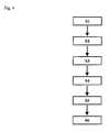
- This method comprises the following steps: providing (S1) at least one beam source, preferably at least one infrared heat radiator or a metal foil radiator, electrically supplying (S2) the at least one beam source with at least one frequency converter which generates a first and a second alternating current, and heating ( S4) of the at least one plastic component by a defined alternating current in the at least one beam source.
- the metal foil radiators are supplied with an individually adjustable electric voltage and a corresponding alternating current.
- These alternating electrical currents provide at least one frequency converter that operates as an electric power supply with two different or equal deliverable currents.
- the frequency converter downstream transformers (S3) a touch-safe alternating voltage for the electrical supply of the at least one beam source is generated.
- the heat radiators are controlled via a bus system (S5). After sufficient plasticization of the plastic components in the joining zone, the at least two heated plastic components are moved into contact with each other, so that the plastic components are welded together (S6).
- the present invention relates to at least one electrically powered by a frequency converter heat radiator.
- various constructions of heat radiators are known which convert supplied electrical energy into thermal radiation. With this heat radiation, plastics and other materials are heated or preheated and thus prepared for further processing.
- plastics are welded together by means of such heat radiators, in particular infrared heat radiators. Such methods are known as infrared welding of plastics.
- infrared welding of plastics are known as infrared welding of plastics.
- the preferred metal foil radiator is known in the art.
- a corresponding construction is in DE 42 42 812 A1 described with respect to the structure and operation of the infrared radiator. It consists of a metal foil, to which an electrical voltage, preferably an electrical alternating voltage, is connected.
- the resulting in the metal foil which acts as an ohmic resistance in the circuit, resulting current flow is converted into heat, which radiates the metal foil.
- the metal foil radiator can be produced in almost any size and shape, whereby almost any surface contour with a plurality of metal foil radiators with heat, preferably uniformly, is irradiated. Based on this heat supply, plastics can be preheated or infrared-welded.
- At least one frequency converter is used in combination with a transformer or directly without an intermediate transformer.
- several frequency inverters are used, each of which is supplied with a known three-phase alternating voltage or with a single-phase alternating voltage.
- Known frequency converters are generally used for the control of three-phase asynchronous motors.
- the frequency of the three-phase asynchronous motor feeding alternating voltage is varied to change the speed of the three-phase motor.
- This principle is also called voltage-controlled frequency converter, which has prevailed since the 90s in a wide application.
- Such frequency converter and also single-phase operated frequency converter comprise a rectifier, which generates a DC voltage from an AC voltage, for example.
- This DC voltage is stabilized and smoothed in a downstream DC link.
- an inverter depending on the required engine speed, the required voltage-frequency ratio is generated in the form of an AC voltage.
- the three components rectifier, DC link and inverter are individually and / or jointly controlled by a higher-level control circuit.
- the control circuit provides the necessary information for generating the speed in the motor and therefore for generating the corresponding voltage-frequency ratio in the frequency converter.
- a frequency converter with a modified functionality compared to known three-phase and single-phase frequency converters is used. Because a metal foil radiator represents an ohmic load in the circuit, which does not have to be controlled with an individually adapted frequency-voltage ratio.
- the frequency converter therefore has no task to vary a frequency or to provide a variable frequency available. Instead, the frequency converter operates as a dual current source or current regulator, at the output of which two individually regulated currents are provided. But it is just of advantage that the frequency at the output of the frequency converter is adjustable. In this way, optimum matching is achieved on the subsequently connected transformers. Since the frequency converter has the three outputs, U, V, W, a first current is provided between the outputs U and V and a second current is provided between the outputs W and V. In this circuit, a total current flows preferably via V.
- the voltage applied to the metal foil radiator preferably a touch safe low voltage of 25 V, is not exceeded. In this way, a health hazard to a worker is avoided by electrical surges.
- the electrical output voltage of the frequency converter is in the order of magnitude of the input voltage, for example, at 400 V in Germany.
- Three-phase networks in other countries provide different input voltages, so that correspondingly different output voltages are preferred.
- the three-phase system supplies 400 V as in Germany.
- the input voltage is also at 400 V, it is in India at 440 V and in the US at 480 V.
- the input voltage of the three-phase network is 200 V.
- the output current of the frequency converter is determined by the power of the frequency converter. This shows the advantage of using a transformer at the output of the frequency converter. To the same extent as the electrical voltage of typically 400 V is transformed to smaller electrical voltages, the available electrical current increases. However, this electrical current is not dangerous for the health of a person touching the metal foil of the metal foil radiator in the case of preferred touch-safe low voltages of, for example, 25 V.
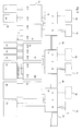
- the Figures 1-2 show various exemplary preferred embodiments of the invention in which metal foil emitters 40; 42; 44; 46; 48; 50 different size and / or design are controlled. These metal foil radiators 40; 42; 44; 46; 48; 50 will be electrically via the frequency converter 10 in combination with a transformer 30; 32; 34 different configuration or powered directly without transformer.
- the frequency converter 10 is in turn supplied via a connected preferred three-phase network, in particular a three-phase network connection, which is designated by the reference numeral 70.
- the three-phase mains connection 70 could likewise be a single-phase mains connection (not shown) which is preferred in accordance with the invention.
- the frequency converter 10 can be controlled individually, for example via a separate control line or control circuit, it is also preferred, the frequency converter 10 via a bus system 60, for example.
- individual frequency converters 60 communicate directly with one another.
- the frequency inverters 12 defined as slaves follow the control commands which the master frequency converter 10 has received via the bus system 60 or another connection.
- Fig. 1 Four metal foil emitters 40a, 40b, 40c, 40d are operated via the frequency converter 10 and the two transformers 30a, 30b.
- the frequency converter 10 provides two individual currents between the outputs U and V as well as W and V. It is also preferable to tap the currents between the outputs U and W as well as V and W.
- the AC voltages of preferably approximately 400 V provided at the outputs U and V as well as W and V are transformed by two identically constructed transformers 30a, 30b into a desired electrical voltage operating range of the connected metal foil radiators 40a-d.
- the general task of the transformers 30 is thus to down-convert the output voltage of the frequency converter 10 to smaller electrical voltages while increasing the possible output current.
- transformers 30 with at least two identical secondary windings, that is, a secondary winding for each metal foil radiator 40, is advantageous.
- the transformers 30 can be flexibly connected to the metal foil radiators 40 to be supplied via the secondary windings. 42; 44; 46; 48; 50 are adjusted.
- the frequency converter 10 also possible.
- the transformers are illustrated at reference numerals 30, 30a, 30b, 30c, and 32.
- the frequency converter 10; 12 the primary winding (not shown) of the transformer 30, 30a, 30b, 30c, and 32.
- the size of the secondary winding and the number of secondary windings is indicated symbolically by the specified voltage values "25 V" at the output of the transformer.
- Fig. 1 shows the use of the transformers 30a, 30b with two equal secondary windings.
- metal foil radiator 40 For a total of four metal foil radiator 40 can be controlled.
- the two metal foil emitters 40a, 40b, 40c, 40d supplied by the same transformer 30a, 30b have the same current and voltage pickup.
- the electrical resistance of the metal foil radiator 40a; 40b; 40c; 40d the defining size.
- This electrical resistance of the two infrared radiators 40a; 40b and 40c, 40d should be the same for the most part. This is generally the case when the two metal foil radiators 40a, 40b; 40c, 40d identically configured, for example, the same width and long, are.
- the metal foil radiators 40c, 40d are larger or smaller, ie longer or shorter or narrower or wider, than the metal foil radiators 40a, 40b of the first transformer 30a. Since, for example, in the case of larger metal foil emitters 40c, 40d, their ohmic resistance also exceeds that of the metal foil emitters 40a, 40b, the current provided by the second transformer 30b must also be greater. These different currents are corresponding to the connected Metal foil radiators 40a, 40b and 40c, 40d supplied by the frequency converter 10 to the two transformers 30a, 30b. In this way, despite a preferred touch-safe low voltage of 25 V, each metal foil radiator 40a, b, c, d can be supplied with the appropriate electrical power. Because the electrical power results from the product of the voltage applied to the metal foil radiator and the flowing electric current. At constant low voltage, therefore, the electrical current through the frequency converter 10 would be increased to provide a metal foil heater with higher power.
- the metal foil radiators 40a-40d are also preferable to supply with a higher electrical voltage than the touch-safe voltage.
- Fig. 2 a likewise preferred control of metal foil radiators 42 is shown.
- the frequency converter 10 controls via the two transformers 30 only two independently operated metal foil radiator 42.
- the transformers 30 are the same as the transformers 30a and 30b Fig. 1 a primary winding in combination with two secondary windings for generating low voltages on.
- the outputs of the two secondary windings of the transformers 30 are connected in series to provide the connected metal foil radiator 42, a higher electrical voltage available.
- Such an electrical circuit is preferably used with longer metal foil radiators 42. These longer metal foil emitters 42 require a higher supply voltage compared to shorter metal foil emitters.
- this electrical circuit can also be realized by means of a transformer (not shown) which has only one secondary winding. This only one secondary winding would then be matched in terms of its winding number to the required higher electrical supply voltage for the connected metal foil radiator 42. It is also preferred to use the transformers 30 Fig. 2 To supply a metal foil radiator 46 having a higher electrical power and thus a higher electrical power consumption. In order to maintain the touch-safe electrical low voltage, of eg. 25V, this higher power of the metal foil radiator 46 (see Fig. 3 ) via the transformer 30, the metal foil radiator 46 must have a higher electric current compared to the metal foil radiator 42 Fig. 2 be supplied.
- the two secondary windings of the transformer 30c, with the secondary windings of the transformer 30 from Fig. 2 are identical, connected in parallel.
- This connection of the outputs of the secondary windings of the transformer 30c leads to an addition of the current strengths which are provided at the outputs of the secondary windings of the transformer 30c.
- the electrical voltage remains constant. It follows that with the interconnection between the transformer 30c and the metal foil radiator 46 according to FIG Fig. 3 a more powerful metal foil radiator 46 can be supplied while maintaining the touch-safe electrical low voltage.
- Fig. 3 shows a further preferred embodiment of the control of multiple metal foil radiator. In this arrangement, different control concepts are combined.
- various frequency converters 10, 12 can be combined with one another via the BUS system 60 already mentioned above.
- each frequency converter 10, 12 is connected to the BUS system 60 and receives about it its individual control information and commands.
- a frequency converter 10 acts as a master frequency converter.
- This master frequency converter 10 is connected to the BUS system 60.
- the other frequency converter 12 in Fig. 3 are configured as slave frequency inverters. These slave frequency converters 12 follow the control information to the master frequency converter 10.
- the slave frequency converters 12 are not connected to the bus system 60. Instead, you will receive directly their control information from the master frequency converter 10, as indicated by the connection lines 65.
- Fig. 3 In the arrangement of Fig. 3 are different control concepts for different metal foil radiators 40, 42, 44, 46, 48, 50 combined.
- the frequency converter 10 is off Fig. 3 connected to two transformers 30 whose supply of metal foil radiators 40, 42 already in connection with the Fig. 1 and 2 has been explained.
- the first transformer 30 preferably operates two electrically identical metal foil emitters 40, while the second transformer 30 operates only one metal foil emitter 42.
- this metal foil radiator 42 is supplied with twice the electrical voltage by the two outputs of the secondary windings of the second transformer 30 are connected in series.
- the in Fig. 3 Centrally arranged frequency converter 12 is connected to a transformer 32, which preferably supplies the electrically identically configured metal foil radiator 44.
- the transformer 32 each includes a secondary winding for each connected metal foil radiator 44. Therefore, it is also preferable to combine in principle any number of (N) secondary windings in the transformer 32 with the primary winding. It should be noted, however, that the current supplied by the frequency converter to the transformer 32 for supplying the metal foil radiator 44 distributed to the individual secondary windings. As a result, the power provided by the frequency converter 12 is distributed at the output UV to the N secondary windings. This split electrical power must still be large enough to operate a connected metal foil radiator 44 satisfactory.
- the two existing secondary windings are connected in parallel. In this way, the electric currents provided by the secondary windings add up, so that although the connected metal foil radiator 46 can be supplied with the preferred low voltage but at the same time with an increased electric current.
- FIG Fig. 3 Another preferred possibility of driving metal foil radiators 48, 50 is shown on the right edge of FIG Fig. 3 shown frequency converter 12.
- the illustrated here Transformer 34 has in comparison to the other transformers 30a, 30b, 30, 32, 30c only one secondary winding, which is tuned to the connected metal foil emitter 48. Although only one secondary coil can be used, the possibility of connecting several metal foil emitters to the transformer 34 is lost, but the electrical supply of the metal foil emitter 48 can be optimally realized. For both the electric current provided by the frequency converter 12 and the electrical voltage realized by the transformer 34 correspond exactly to the connected metal foil radiator 48 in order to realize its optimum electrical output.
- a metal foil radiator 50 is connected directly without the interposition of a transformer. With the aid of this electrical circuit, the full output voltage supplied by the frequency converter is available to the metal foil radiator 50. At the same time, however, the electrical current supplied by the frequency converter is lower than when a transformer between frequency converter 12 and metal foil radiator 50 would have been switched. Especially with long metal foil radiators, ie metal foil radiator with a high ohmic resistance, such a control as in the metal foil radiator 50 is useful. In addition, it is preferred to use such a control when these metal foil radiators are not accessible by a worker. In this case, it is not necessary to operate the metal foil radiator 50 with a touch-safe low-voltage electrical.
- Each of the drive concepts for metal foil emitters shown or indicated here in combination with a frequency converter and a transformer or without a transformer can be arbitrarily combined with another control concept.
- a drive configuration not shown is to use a transformer with five secondary windings to drive five electrically identical metal foil radiators.
- a metal foil radiator can be connected directly to the frequency converter without an intermediate transformer. It is also preferable to transform the electrical operating voltage upwards by means of the intermediate transformers. This would then require appropriate radiant heaters, which can be operated with non-touch-safe low voltages.
- N 1
- N 1
- the number of metal foil emitters N can also be arbitrarily increased, so that then three, four or more metal foil emitters are supplied via the frequency converter in combination with the transformer.
- a disadvantage of the use of transformers are their magnetization losses. By providing the electrical voltage at the input of the transformer as a high frequency sine signal, this problem is minimized. Because with increasing frequency of this sine signal of the electrical input voltage, the magnetization loss decreases. In this way, then a smaller design of the transformer can be used. In this context, it is inventively preferred to use a frequency of 300 Hz, which involves a compromise between the control speed of the frequency converter and the highest possible frequency for reducing the magnetization losses. In this context, however, it is also preferred to use other frequencies.
- the use of low-voltage transformers is advantageous.
- the low-voltage transformers transform the output voltage of the frequency converter 10 into an alternating voltage range of 0 V to 50 V and according to a further preferred embodiment in a range of 0 V to 25 V.
- the transformers are additionally required, but due to their use can be a power supply to a clear smaller and less expensive frequency converter.
- the circuit concepts described above are used for heating and / or infrared welding of plastic components.
- the majority of metal foil radiators are driven in accordance with the above concepts, so that they emit their heat radiation to the adjacently arranged plastic components.
- Such an arrangement thus brings the plastic component in the immediate vicinity of the metal foil radiator, so that the heat impinges in the surface region of the plastic component.
- the arrangement moves the plastic component for further processing to, for example, a second plastic component in order to weld it thereto.
- the two plastic components in their heated joining zones against each other pressed so that after cooling of the joining zones, there is a bond between these two plastic components. This procedure is commonly known as infrared welding.
Landscapes
- Physics & Mathematics (AREA)
- Electromagnetism (AREA)
- Health & Medical Sciences (AREA)
- Toxicology (AREA)
- Engineering & Computer Science (AREA)
- Mechanical Engineering (AREA)
- Optics & Photonics (AREA)
- Lining Or Joining Of Plastics Or The Like (AREA)
- Resistance Heating (AREA)
Abstract
Description
- Die vorliegende Erfindung betrifft einen Wärmestrahler, insbesondere einen Infrarotstrahler, eine Vorrichtung zum Infrarotschweißen von mindestens zwei Kunststoffbauteilen sowie ein Verfahren zum Erwärmen oder Verschweißen von mindestens einem Kunststoffbauteil.
- In den letzten Jahren hat das Schweißen von Kunststoffen mittels Infrarotstrahlung große Verbreitung gefunden. Hierbei werden die zu verschweißenden Kunststoffteile im Bereich der Schweißnaht mittels Infrarotstrahlung erwärmt und danach gefügt. Der Vorteil dieser Technologie gegenüber Reibschweißverfahren, wie z. B. dem Vibrations- oder Rotationsschweißen, besteht u. a. in der Vermeidung der in der Trockenreibphase entstehenden Staub- und Faserpartikel. Diese Partikel verschmutzen und beeinträchtigen die herzustellende Schweißverbindung. Zudem stellen sie eine Belastung der Arbeitsumgebung dar.
- Neben dem Infrarotschweißen von Kunststoffen werden derartige Infrarotstrahler auch zur Vorwärmung oder Vorplastifizierung von Kunststoffbauteilen in Kombination mit dem Vibrationsschweißen eingesetzt. Der Verfahrensablauf des Infrarotschweißens ähnelt dem Heizelementschweißen von Kunststoffen. Im Unterschied zum Heizelementschweißen werden die Schweißzonen beider Kunststoff-Fügepartner berührungslos durch die Absorption der Wärmestrahlungsenergie erwärmt. Auf diese Weise wird ein Materialrückstand durch Anhaften der Schmelze des Kunststoffbauteils am Heizelement vermieden. Da die Fügeflächen der miteinander zu verbindenden Kunststoffbauteile meist uneben ausgebildet sind und zudem gewissen Toleranzen unterliegen, ist der Abstand von bestimmten Abschnitten der Kunststoffbauteile zum Wärmestrahler ungleichmäßig. Dies hat eine inhomogene Erwärmung der Fügezone, d. h. der zu erwärmenden Bereiche der Kunststoffbauteile, zur Folge.
- Nach Erreichen einer gewünschten Schmelzeschichtdicke am Kunststoffbauteil wird die Erwärmphase der Infrarotstrahler durch die Fügephase abgelöst. Dabei wird das Strahlerelement aus der Fügeebene bzw. aus der Umgebung der Kunststoffbauteile wegbewegt. Die Fügephase der Kunststoffbauteile beginnt mit der gegenseitigen Berührung der Fügeflächen. Während die Fügeflächen gegeneinander gepresst werden, erfolgt eine Abkühlung und somit Aushärtung und Verbindung der Kunststoffbauteile. Sobald diese Verbindung hergestellt ist, ist das Infrarotschweißen abgeschlossen.
- Beim Infrarotschweißen kommen je nach Anwendung unterschiedliche Strahlerarten zum Einsatz. Zu diesen Strahlerarten zählen bspw. kurzwellige Strahler mit Wellenlänge von 1,6 µm, wie etwa Halogenstrahler. Des Weiteren werden mittelwellige Strahler mit Wellenlängen zwischen 1,6 µm und 3,5 µm genutzt, wie bspw. Metallfolienstrahler. Eine weitere Alternative stellen langwellige Strahler dar, die einen Wellenlängenbereich oberhalb 3,5 µm abdecken, wie bspw. Quarzstrahler. In diesem Zusammenhang sollte erwähnt werden, dass ein thermischer Strahler die Wärmestrahlung nicht bei genau einer Wellenlänge imitiert, sondern vielmehr in einem Wellenlängenspektrum. Auch die Absorptionseigenschaften der Kunststoffe und damit die Erwärmung der Fügezone können sehr unterschiedlich ausfallen. Ein wesentlicher Vorteil des Infrarotschweißens besteht somit in dem fehlenden Kontakt zwischen der Heizquelle und dem Kunststoff, wodurch eine Verschmutzung der Heizquelle durch Kunststoffablagerungen vermieden wird. Ein weiterer Vorteil besteht in der Anwendung der Infrarotstrahler oder generell der Wärmestrahler als Vorwärmquelle in anderen kunststoffverarbeitenden Verfahren. So wird bspw. beim Vibrationsschweißen der Kunststoff mittels Infrarotstrahlung im Schweißnahtbereich vorgewärmt, um auf diese Weise die Geschwindigkeit beim Vibrationsschweißen zu erhöhen. Um komplexe, d. h. dreidimensionale und lange, Schweißnahtgeometrien mittels Infrarotstrahler zu erwärmen, bzw. zu Verschweißen, sind häufig mehrere Strahler erforderlich. Auch ist es technisch von Vorteil, die Länge der Strahler zu begrenzen. Je kürzer die Wärmestrahler sind, umso geringer ist der technische Aufwand, um diese im Schadensfall auszutauschen. In erster Linie ist aber von Vorteil, dass viele kleine Strahlerelemente eine homogenere Erwärmung der Kunststoffbauteile ermöglichen. Denn jedes dieser Strahlerelemente ist für sich unabhängig von den anderen Strahlerelementen optimal an den entsprechenden zu erwärmenden Bereich des Kunststoffbauteils anpassbar. Bei großen Kunststoffbauteilen werden bspw. 20 oder mehr Wärmestrahlerelemente benötigt.
- Bei der Verwendung von Metallfolienstrahlern ist von Nachteil, dass die Metallfolie eines Metallfolienstrahlers frei zugänglich ist und daher als spannungsführendes Element gewissen Sicherheitsanforderungen unterliegt. Um diese zu erfüllen, sind aufwändige Schutzmaßnahmen nötig, sodass der Werker nicht die Metallfolie berühren kann. Vorteilhafterweise sind Metallfolienstrahler mit geringem Aufwand an die Oberflächenkontur eines Kunststoffbauteils anpassbar.
- Es ist daher die Aufgabe vorliegender Erfindung, einen Wärmestrahler, eine Vorrichtung zum Infrarotschweißen sowie ein Verfahren zum Erwärmen oder Verschweißen von Kunststoffbauteilen bereitzustellen, die im Vergleich zu bekannten Konstruktionen und Verfahren flexibel und wirtschaftlich realisierbar sind.
- Die oben genannten Aufgabe wird durch einen Wärmestrahler gemäß dem unabhängigen Patentanspruch 1, einer Vorrichtung zum Infrarotschweißen von mindestens zwei Kunststoffbauteilen gemäß dem unabhängigen Patentanspruch 2 sowie durch ein Verfahren zum Erwärmen oder Verschweißen von mindestens einem Kunststoffbauteil gemäß dem unabhängigen Patentanspruch 8 gelöst. Vorteilhafte Ausgestaltungen und Weiterentwicklungen vorliegender Erfindung gehen aus den abhängigen Ansprüchen sowie der Beschreibung in Kombination mit den entsprechenden Zeichnungen hervor.
- Der erfindungsgemäße Wärmestrahler, insbesondere ein Infrarotstrahler, weist die folgenden Merkmale auf: mindestens eine Strahlquelle, mit der zugeführte elektrische Energie in Wärmestrahlung umwandelbar ist, und eine Steuerung umfassend mindestens einen Frequenzumrichter mit einem ersten, einem zweiten und einem dritten Ausgang, sodass zwischen dem ersten und dritten Ausgang ein erster Wechselstrom sowie zwischen dem zweiten und dritten Ausgang ein zweiter Wechselstrom bereitstellbar ist, mit denen die mindestens eine Strahlquelle oder eine Mehrzahl von Strahlquellen betreibbar ist.
- Wärmestrahler werden einerseits zum Erwärmen von Kunststoffbauteilen zur Vorbereitung bspw. des Vibrationsschweißens eingesetzt. Ein weiteres Anwendungsgebiet stellt das Infrarotschweißen von Kunststoffbauteilen dar. Hier dienen die Wärmestrahler der berührungslosen Erwärmung der Kunststoffbauteile, die nachfolgend miteinander verbunden werden.
- Derartige Wärmestrahler und gemäß einer bevorzugten Ausführungsform Infrarotstrahler oder Metallfolienstrahler stellen in der elektrischen Betrachtung ohmsche Verbraucher dar. Schließt man diese Wärmestrahler an eine elektrische Spannung an, fließt ein elektrischer Strom durch den Wärmestrahler, der im Wärmestrahler in Wärmestrahlung umgewandelt wird. Gerade Metallfolienstrahler sind geeignet zum Erwärmen und Verschweißen von Kunststoffbauteilen, da sie sich allein oder in Kombination mit mehreren Metallfolienstrahler optimal an eine Bauteilgeometrie anpassen lassen. Da jedoch die stromdurchflossene Metallfolie des Metallfolienstrahlers frei zugänglich ist, stellt die an der Metallfolie anliegende elektrische Spannung ein gesundheitliches Risiko für den Werker bei Berührung des Wärmestrahlers dar.
- Um dieses Risiko zu minimieren, wird der Wärmestrahler erfindungsgemäß mithilfe mindestens eines Frequenzumrichters angesteuert. Bekannte Frequenzumrichter werden zur Ansteuerung von Drehstrommotoren verwendet, wobei der Frequenzumrichter an ein Drehstromnetz mit einer Drei-Phasen-Wechselspannung angeschlossen ist. Zu diesem Zweck werden zumeist spannungsgeführte Frequenzumrichter eingesetzt, die mit ihren drei Ausgängen U, V, W die entsprechenden drei Eingänge eines Drehstrommotors versorgen. Im Unterschied zu diesen bekannten Frequenzumrichtern liefert der erfindungsgemäß genutzte Frequenzumrichter einen ersten und einen zweiten Wechselstrom, die zum Betrieb und zur Ansteuerung von mindestens einem oder einer Mehrzahl von Wärmestrahlern genutzt werden. Der erste Wechselstrom ist zwischen dem ersten und dritten Ausgang des Frequenzumrichters und der zweite Wechselstrom ist zwischen dem zweiten und dem dritten Ausgang des Frequenzumrichters abgreifbar. Diese unterschiedlichen ersten und zweiten Wechselströme, die vom Betrag her aber auch gleich sein können, sind nutzbar, um einen oder mehrere Wärmestrahler, im Speziellen Metallfolienstrahler, anzusteuern. Die ersten und zweiten Wechselströme werden durch den Frequenzumrichter in Kombination mit einer entsprechenden ersten und zweiten Wechselspannung bereitgestellt. Um den Betrieb der Metallfolienstrahler positiv zu beeinflussen, werden der erste und dritte Ausgang des Frequenzumrichters und/oder der zweite und dritte Ausgang des Frequenzumrichters jeweils mit einem Transformator verbunden, um die durch den Frequenzumrichter jeweils bereitgestellte elektrische Wechselspannung in einen vorbestimmten Betriebsbereich zu transformieren. Dieser Betriebsbereich liegt vorzugsweise oberhalb oder unterhalb der elektrischen Ausgangsspannung des Frequenzumrichters. Vorzugsweise dient mindestens einer der Transformatoren dazu, die elektrische Wechselspannung des Frequenzumrichters in einen Niederspannungsbereich zu transformieren, der als berührungssicher angesehen wird. Dies bedeutet im Speziellen, dass bspw. ein Werker einen Metallfolienstrahler berühren darf, der an eine derart berührungssichere elektrische Spannung angeschlossen ist. Denn diese berührungssichere elektrische Spannung, die bspw. in einem Bereich unterhalb von 40 V oder unterhalb von 25 V liegt, führt nicht zu gesundheitlichen Schädigungen des damit in Kontakt kommenden Werkers. In diesem Zusammenhang ist hervorzuheben, dass neben den mit den mit Drei-Phasen-Wechselspannung betriebenen Frequenzumrichtern erfindungsgemäß bevorzugt auch mit einer Ein-Phasen-Wechselspannung betriebene Frequenzumrichter genutzt werden. Während des Betriebs des mit Ein-Phasen-Wechselspannung betriebenen Frequenzumrichters sorgt der entsprechend programmierte Steuerkreis des Frequenzumrichters (siehe unten) dafür, dass am Ausgang des Frequenzumrichters zwei Stromausgänge mit entsprechenden Wechselspannungen bereitgestellt werden. Daraus folgt, dass im Vergleich zu mit Drei-Phasen-Wechselspannung betriebenen Frequenzumrichtern die elektrische Versorgung des mit Ein-Phasen-Wechselspannung betriebenen Frequenzumrichters zwar anders ist, am Ausgang des mit Ein-Phasen-Wechselspannung betriebenen Frequenzumrichters aber die gleichen technischen Merkmale bzw. Voraussetzungen, wie elektrische Wechselströme und elektrische Wechselspannungen, vorliegen wie an dem mit Drei-Phasen-Wechselspannung betriebenen Frequenzumrichter.
- Basierend auf der oben beschriebenen Ansteuerung eines Wärmestrahlers mithilfe eines speziell daran angepassten Frequenzumrichters umfasst vorliegende Erfindung ebenfalls eine Vorrichtung zum Infrarotschweißen von mindestens zwei Kunststoffbauteilen. Diese Vorrichtung zum Infrarotschweißen weist die folgenden Merkmale auf: mindestens eine Strahlquelle, mit der zugeführte elektrische Energie in Wärmestrahlung umwandelbar ist, insbesondere einen Metallfolienstrahler, und mit der Kunststoffbauteile erwärmbar sind, eine Steuerung umfassend mindestens einen Frequenzumrichter, mit einem ersten, einem zweiten und einem dritten Ausgang, sodass zwischen dem ersten und dritten Ausgang ein erster Wechselstrom sowie zwischen dem zweiten und dritten Ausgang ein zweiter Wechselstrom zur Versorgung der mindestens einen Strahlquelle generierbar ist, und eine Anordnung zum Halten und Bewegen der Kunststoffbauteile, sodass diese nach dem Erwärmen durch die mindestens eine Strahlquelle in Anlage bringbar und miteinander verschweißbar oder zu einer weiteren Verarbeitungsstelle bringbar sind.
- Die erfindungsgemäße Vorrichtung zum Infrarotschweißen von mindestens zwei Kunststoffbauteilen basiert auf den gleichen Komponenten wie der oben beschriebene Wärmestrahler. Daher gelten die obigen technischen Charakterisierungen des Wärmestrahlers und des damit in Verbindung genutzten Frequenzumrichters in gleicher Weise auch für die hier genannte Vorrichtung zum Infrarotschweißen.
- Wie bereits oben dargelegt worden ist, ist mithilfe einer Mehrzahl von Wärmestrahlern oder Metallfolienstrahlern eine optimale Anpassung der Strahlergeometrie an die Bauteilgeometrie realisierbar. Die Verwendung vieler kleiner Wärmestrahler hat zudem den Vorteil, dass diese mit einer geringeren elektrischen Spannung betrieben werden können als bspw. langgestreckte Strahlersegmente. Somit wird durch die Segmentierung des Wärmestrahlers bzw. durch die Nutzung einer Vielzahl kleinerer Wärmestrahler, wie bspw. Metallfolienstrahler, die erforderliche elektrische Versorgungsspannung auf vorzugsweise 25 V Wechselspannung oder darunter gesenkt. Damit befindet man sich im Bereich der elektrischen Kleinspannungen, sodass Maschinen und Schweißwerkzeuge sicherungstechnisch mit geringeren Auflagen und somit einfacher realisiert werden können. Denn eine versehentliche Berührung eines offen liegenden Metallfolienstrahlers durch einen Werker führt nicht zu einem gesundheitsgefährdenden elektrischen Spannungsstoß.
- Um jeden Wärmestrahler bzw. jedes Wärmestrahlersegment unabhängig ansteuern zu können, wurde bisher jedes Segment mit einer eigenen Strom- und Spannungsversorgung angesteuert. Dies hat einen erheblichen Aufwand aufgrund der hohen Anzahl an Stromnetzteilen zur Folge. Zudem erfordert jedes Stromnetzteil eine eigene Regelung, was wirtschaftlich kaum vertretbare Kosten zur Folge hat. Daher ist es erfindungsgemäß bevorzugt, dass der erste und/oder der zweite Transformator eine Primärwicklung und eine oder eine Mehrzahl von Sekundärwicklungen aufweist, um eine oder eine Mehrzahl von Strahlquellen elektrisch versorgen zu können. Zu diesem Zweck sind die Sekundärwicklungen in ihrer Anzahl auf die Anzahl der elektrisch zu versorgenden Wärmestrahler abgestimmt. Des Weiteren ist das Wicklungsverhältnis von Primärwicklung zu Sekundärwicklung derart dimensioniert, dass der optimale elektrische Betriebsbereich für den anzusteuernden Wärmestrahler, bspw. den Metallfolienstrahler, erzielbar ist. So ist vorzugsweise über die geeignete Dimensionierung der Sekundärwicklung eine elektrische Kleinspannung erzeugbar, mit der berührungssicher ein Metallfolienstrahler betrieben werden kann. In gleicher Weise ist es bevorzugt, die Sekundärwicklung bzw. die Sekundärwicklungen an eine elektrische Versorgung von einer Mehrzahl von Metallfolienstrahlern anzupassen. Denn je nach elektrischer Zusammenschaltung von mehrerer Metallfolienstrahlern, die jeweils als ohmscher Verbraucher in einem elektrischen Stromkreis wirken, sind bekannte Berechnungsvorschriften anwendbar, die einen gewünschten elektrischen Betriebs- bzw. Versorgungsbereich der einzelnen Metallfolienstrahler garantieren.
- Entsprechend dieser allgemeinen Zusammenfassung vorliegender Erfindung fungiert der Frequenzumrichter als Stromnetzteil, das zwei voneinander unabhängige und im Wert verschiedene oder gleiche Stromstärken liefern kann. In Kombination mit den oben genannten Transformatoren sind zudem berührungssichere elektrische Betriebsspannungen für die mindestens eine Strahlquelle generierbar.
- Gemäß einer bevorzugten Ausführungsform vorliegender Erfindung ist eine beliebige Bauart eines Wärmestrahlers in Kombination mit der oben beschriebenen Schaltung einsetzbar. Erfindungsgemäß bevorzugt wird als Wärmestrahler aber ein Metallfolienstrahler oder eine Mehrzahl von Metallfolienstrahlern eingesetzt.
- Gemäß einer weiteren bevorzugten Ausführungsform vorliegender Erfindung wird eine Mehrzahl von Frequenzumrichtern zur elektrischen Versorgung der Wärmestrahler eingesetzt. Diese Mehrzahl an Frequenzumrichtern ist über ein in BUS-System miteinander verbunden und ansteuerbar. Ein derartiges BUS-System stellt sicher, dass die einzelnen Frequenzumrichter in effektiver Weise einzelnen ansteuerbar sind. Zudem ist der Schaltungsaufwand zur Realisierung einer derartig individuellen Ansteuerung der Frequenzumrichter aufgrund dieses BUS-Systems begrenzt. Aufgrund der individuellen Ansteuerung der einzelnen Metallfolienstrahler mithilfe des BUS-Systems sind zudem unterschiedliche Abstände zwischen Kunststoffbauteil und Wärmestrahler nicht nur durch eine erhöhte Anzahl von Wärmestrahlern ausgleichbar, sondern ebenfalls durch eine individuell unterschiedliche Ansteuerung der einzelnen Wärmestrahler in unterschiedlichen Bauteilsegmenten.
- Vorliegende Erfindung offenbart zudem ein Verfahren zum Erwärmen oder Verschweißen von mindestens einem Kunststoffbauteil. Dieses Verfahren weist die folgenden Schritte auf: Bereitstellen (S1) mindestens einer Strahlquelle, vorzugsweise mindestens eines Infrarotwärmestrahlers oder eines Metallfolienstrahlers, elektrisches Versorgen (S2) der mindestens einen Strahlquelle mit mindestens einem Frequenzumrichter, der einen ersten und einen zweiten Wechselstrom erzeugt, und Erwärmen (S4) des mindestens einen Kunststoffbauteils durch einen definierten Wechselstrom in der mindestens einen Strahlquelle.
- Entsprechend den obigen Beschreibungen werden die Metallfolienstrahler durch eine individuell anpassbare elektrische Spannung und einen entsprechenden Wechselstrom versorgt. Diese elektrischen Wechselströme stellt mindestens ein Frequenzumrichter bereit, der als ein elektrisches Stromnetzteil mit zwei unterschiedlichen oder gleichen bereitstellbaren Strömen arbeitet. Mithilfe von vorzugsweise dem Frequenzumrichter nachgeschalteten Transformatoren (S3) wird eine berührungssichere Wechselspannung für die elektrische Versorgung der mindestens einen Strahlquelle erzeugt.
- Um zwei Kunststoffbauteile gezielt zu erwärmen und nachfolgend miteinander zu verschweißen, werden vorzugsweise die Wärmestrahler über ein BUS-System angesteuert (S5). Nach ausreichender Plastifizierung der Kunststoffbauteile in der Fügezone, werden die mindestens zwei erwärmten Kunststoffbauteile in Anlage zueinander bewegt, sodass die Kunststoffbauteile miteinander verschweißt werden (S6).
- Die vorliegende Erfindung wird unter Bezugnahme auf die begleitende Zeichnung näher erläutert. Es zeigen:
- Figur 1
- eine erste bevorzugte Ausführungsform vorliegender Erfindung, mit der vier Wärmestrahler angesteuert werden,
- Figur 2
- eine weitere bevorzugte Ausführungsform vorliegender Erfindung, bei der zwei Wärmestrahler angesteuert werden,
- Figur 3
- eine weitere bevorzugte Ausführungsform vorliegender Erfindung, bei der eine Mehrzahl von Wärmestrahlern angesteuert wird und
- Figur 4
- ein Flussdiagramm einer bevorzugten Ausführungsform des erfindungsgemäßen Verfahrens zum Erwärmen oder Verschweißen von mindestens einem Kunststoffbauteil.
- Vorliegende Erfindung betrifft mindestens einen mithilfe eines Frequenzumrichters elektrisch betriebenen Wärmestrahler. Wie oben bereits erläutert worden ist, sind verschiedene Konstruktionen von Wärmestrahlern bekannt, die zugeführte elektrische Energie in eine Wärmestrahlung umwandeln. Mit dieser Wärmestrahlung werden Kunststoffe und andere Materialien erwärmt oder vorgewärmt und dadurch zur weiteren Verarbeitung vorbereitet. Zudem werden Kunststoffe mithilfe von derartigen Wärmestrahlern, insbesondere Infrarotwärmestrahler, miteinander verschweißt. Derartige Verfahren sind bekannt als Infrarotschweißen von Kunststoffen. Im Weiteren wird die Verwendung, die Ansteuerung, der Betrieb von Wärmestrahlern anhand von Metallfolienstrahlern erläutert. Somit gelten alle Erläuterungen auch für andere Wärmestrahler.
- Der bevorzugte Metallfolienstrahler ist im Stand der Technik bekannt. Eine entsprechende Konstruktion ist in
DE 42 42 812 A1 beschrieben, auf die im Hinblick auf Aufbau und Funktionsweise des Infrarotstrahlers Bezug genommen wird. Er besteht aus einer Metallfolie, an die eine elektrische Spannung, vorzugsweise eine elektrische Wechselspannung, angeschlossen wird. Der daraufhin in der Metallfolie, die als ohmscher Widerstand im Stromkreis wirkt, entstehende Stromfluss wird in Wärme umgewandelt, die die Metallfolie abstrahlt. Die Metallfolienstrahler sind fast in jeder beliebigen Größe und Form herstellbar, wodurch nahezu jede beliebige Oberflächenkontur mit einer Mehrzahl von Metallfolienstrahlern mit Wärme, vorzugsweise gleichmäßig, bestrahlbar ist. Basierend auf dieser Wärmezufuhr sind Kunststoffe vorwärmbar oder infrarotverschweißbar. Das Vorwärmen mittels Infrarotstrahler in Kombination mit dem Kunststoffschweißen ist inDE 197 52 648 C2 erläutert.DE 101 22 802 A1 beschreibt eine Strahlerkonstruktion und ein Verfahren zum Vorwärmen von Kunststoffbauteilen in Kombination mit dem bekannten Vibrations- oder Reibschweißen.DE 601 10 536 T2 ist ebenfalls die Beschreibung eines Infrarotstrahlers sowie dessen Einsatz beim Infrarot- bzw. Kunststoffschweißen entnehmbar. Auf die oben genannten Dokumente wird bezüglich der Konstruktion von Infrarotstrahlern sowie der Gestaltung, des Ablaufs von Vorwärm- und Kunststoffschweißverfahren und deren Kombination Bezug genommen. - Um die Mehrzahl der zum Erwärmen oder Infrarotschweißen erforderlichen Metallfolienstrahler anzustrahlen, wird erfindungsgemäß mindestens ein Frequenzumrichter in Kombination mit einem Transformator oder direkt ohne zwischengeschalteten Transformator genutzt. Je nach Anzahl der anzusteuernden Metallfolienstrahler werden mehrere Frequenzumrichter verwendet, die jeweils mit einer bekannten Drei-Phasen-Wechselspannung oder mit einer Ein-Phasen-Wechselspannung versorgt werden.
- Bekannte Frequenzumrichter werden generell für die Steuerung von Drehstromasynchronmotoren verwendet. Dabei wird die Frequenz der den Drehstromasynchronmotor speisenden Wechselspannung variiert, um die Drehzahl des Drehstrommotors zu verändern. Dieses Prinzip nennt man auch spannungsgeführten Frequenzumrichter, das sich seit den 90iger Jahren in breiter Anwendung durchgesetzt hat.
- Derartige Frequenzumrichter und auch einphasig betriebene Frequenzumrichter umfassen einen Gleichrichter, der aus einer Wechselspannung, bspw. die versorgende drei Phasen Wechselspannung, eine Gleichspannung erzeugt. Diese Gleichspannung wird in einem nachgeschalteten Zwischenkreis stabilisiert und geglättet. Dann wird in einem Wechselrichter in Abhängigkeit von der geforderten Motordrehzahl das benötigte Spannungs-Frequenz-Verhältnis in Form einer Wechselspannung erzeugt. Die drei Komponenten Gleichrichter, Zwischenkreis und Wechselrichter werden einzeln und/oder gemeinsam durch einen übergeordneten Steuerkreis angesteuert. In bekannten Frequenzumrichtern gibt der Steuerkreis die notwendige Information zur Erzeugung der Drehzahl im Motor und daher zur Erzeugung des entsprechenden Spannungs-Frequenz-Verhältnisses im Frequenzumrichter vor.
- Zur Ansteuerung der bevorzugten Mehrzahl von Metallfolienstrahlern wird ein Frequenzumrichter mit abgewandelter Funktionalität im Vergleich zu bekannten dreiphasigen und einphasigen Frequenzumrichtern (siehe oben) eingesetzt. Denn ein Metallfolienstrahler stellt eine ohmsche Last im Stromkreis dar, der nicht mit einem individuell angepassten Frequenz-Spannungs-Verhältnis angesteuert werden muss. Der Frequenzumrichter hat daher nicht die Aufgabe, eine Frequenz zu variieren oder eine variable Frequenz zur Verfügung zu stellen. Stattdessen arbeitet der Frequenzumrichter als eine duale Stromquelle oder Stromregelung, an deren Ausgang zwei individuell geregelte Ströme bereitgestellt werden. Dabei ist aber gerade von Vorteil, dass die Frequenz am Ausgang des Frequenzumrichters einstellbar ist. Auf diese Weise wird eine optimale Abstimmung auf die nachfolgend angeschlossenen Transformatoren erzielt. Da der Frequenzumrichter die drei Ausgänge, U, V, W aufweist, wird ein erster Strom zwischen den Ausgängen U und V und ein zweiter Strom zwischen den Ausgängen W und V bereitgestellt. Bei dieser Schaltung fließt ein Summenstrom vorzugsweise über V ab.
- Voraussetzung für den Einsatz von Frequenzumrichtern zur Stromversorgung von Metallfolienstrahlern ist die Entwicklung einer entsprechenden Software, die im Steuerkreis des Frequenzumrichters eingesetzt wird. Diese Software stellt sicher, dass einer der drei Ausgänge des Frequenzumrichters für den Ablauf des Summenstroms der anderen beiden Ausgänge genutzt werden kann. Zudem sorgt diese Software für eine passende Stromregelung im Frequenzumrichter, da die als ohmsche Verbraucher arbeitenden Metallfolienstrahler über den Strom geregelt werden müssen. Es ist bevorzugt, diese Stromregelung über einen PI-Regler zu realisieren. Natürlich sind auch andere Regler, wie z. B. ein PID-Regler möglich. Des Weiteren beinhaltet diese Software verschiedene Überwachungsfunktionen. In diesem Zusammenhang ist es bspw. bevorzugt, die elektrischen Ausgangsspannungen am Frequenzumrichter zu überwachen. Auf diese Weise kann sichergestellt werden, dass auch im Störungsfall die am Metallfolienstrahler anliegende elektrische Spannung, vorzugsweise eine berührungssichere Niedrigspannung von 25 V, nicht überschritten wird. Auf diese Weise wird eine gesundheitliche Gefährdung eines Werkers durch elektrische Überspannungen vermieden.
- Vorzugsweise liegt die elektrische Ausgangsspannung des Frequenzumrichters in der Größenordnung der Eingangsspannung, bspw. bei 400 V in Deutschland. Drehstromnetze in anderen Ländern liefern andere Eingangsspannungen, sodass hier entsprechend auch andere Ausgangsspannungen bevorzugt sind. In den meisten Ländern Europas liefert das Drehstromnetz 400 V wie in Deutschland. Während in Mexiko und Brasilien die Eingangsspannung ebenfalls bei 400 V liegt, ist sie in Indien bei 440 V und in den USA bei 480 V. In Japan liegt die Eingangsspannung des Drehstromnetzes bei 200 V.
- Der Ausgangsstrom des Frequenzumrichters wird dagegen durch die Leistung des Frequenzumrichters bestimmt. Hier zeigt sich der Vorteil bei der Verwendung eines Transformators am Ausgang des Frequenzumrichters. Im selben Maße, wie die elektrische Spannung von typisch 400 V auf kleinere elektrische Spannungen transformiert wird, steigt der zur Verfügung stehende elektrische Strom. Diese elektrische Stromstärke ist aber bei bevorzugten berührungssicheren Niedrigspannungen von bspw. 25 V nicht gefährlich für die Gesundheit einer die Metallfolie des Metallfolienstrahlers berührenden Person.
- Prinzipiell ist anstelle der oben genannten Stromregelung im Frequenzumrichter auch eine Spannungsregelung möglich. Dazu müssten jedoch die verschiedenen elektrischen Widerstände im Betriebsstromkreis des Metallfolienstrahlers, wie bspw. Übergangswiderstände, Leitungswiderstände, temperaturabhängige Widerstände des Strahlers, bekannt sein oder zunächst ermittelt werden. Ohne diese Werte, die nur mit großem Aufwand bestimmbar sind, ist eine genaue Spannungsregelung nicht sicher zu stellen. Ein derartiger Aufwand entfällt aber bei der bevorzugten und oben beschriebenen Stromregelung durch den Frequenzumrichter.
- Die
Figuren 1-2 zeigen unterschiedliche beispielgebende bevorzugte Ausführungsformen der Erfindung, in denen Metallfolienstrahler 40; 42; 44; 46; 48; 50 unterschiedlicher Größe und/oder Bauart angesteuert werden. Diese Metallfolienstrahler 40; 42; 44; 46; 48; 50 werden elektrisch über den Frequenzumrichter 10 in Kombination mit einem Transformator 30; 32; 34 unterschiedlicher Konfiguration oder direkt ohne Transformator versorgt. Der Frequenzumrichter 10 wird wiederum über ein angeschlossenes bevorzugtes Drehstromnetz versorgt, im speziellen ein Drei-Phasen-Netzanschluss, das mit dem Bezugszeichen 70 benannt ist. Der Drei-Phasen-Netzanschluss 70 könnte in gleicher Weise auch ein erfindungsgemäß bevorzugter Ein-Phasen-Netzanschluss (nicht gezeigt) sein. Während hier der Frequenzumrichter 10 einzeln angesteuert werden kann, beispielsweise über eine separate Steuerleitung oder Steuerschaltung, ist es ebenfalls bevorzugt, den Frequenzumrichter 10 über ein BUS-System 60, bspw. ein CAN-Bus oder ein PROFI-Bus, mit Steuer- und Betriebsinformationen zu versorgen. Ergänzend zum BUS-System 60 oder in Kombination mit dem BUS-System 60 kommunizieren einzelne Frequenzumrichter 60 direkt miteinander. In diesem Zusammenhang ist es bevorzugt, einen Frequenzumrichter 10 als Master und die daran angeschlossenen Frequenzumrichter 10 als Slave zu betreiben (sieheFig. 3 ). In diesem Fall folgen die als Slave definierten Frequenzumrichter 12 den Steuerungsbefehlen, die der Master-Frequenzumrichter 10 über das BUS-System 60 oder eine andere Verbindung erhalten hat. - In
Fig. 1 werden vier Metallfolienstrahler 40a, 40b, 40c, 40d über den Frequenzumrichter 10 und die beiden Transformatoren 30a, 30b betrieben. Als duale Stromquelle stellt der Frequenzumrichter 10 zwischen den Ausgängen U und V sowie W und V zwei individuelle Stromstärken bereit. Es ist ebenfalls bevorzugt, die Ströme zwischen den Ausgängen U und W sowie V und W abzugreifen. Die an den Ausgängen U und V sowie W und V bereitgestellten Wechselspannungen von vorzugsweise ca. 400 V werden durch zwei baugleiche Transformatoren 30a, 30b in einen gewünschten elektrischen Spannungs-Betriebsbereich der angeschlossenen Metallfolienstrahler 40a-d transformiert. Die allgemeine Aufgabe der Transformatoren 30 ist somit das Heruntertransformieren der Ausgangsspannung des Frequenzumrichters 10 auf kleinere elektrische Spannungen bei gleichzeitigem Erhöhen des möglichen Ausgangsstroms. Denn durch die Verwendung kleiner elektrischer Spannungen werden automatisch Sicherheitsvorschriften eingehalten. Gleichzeitig stehen höhere elektrische Ströme zur Verfügung, für die sonst ein leistungfähiger Frequenzumrichter 10 eingesetzt werden müsste. Sollten sich die gesetzlichen Grenzwerte für berührungssichere elektrische Niederspannungen ändern, dann kann vorzugsweise immer der Transformator 30 im Zusammenhang mit dem bzw. den angeschlossenen Metallfolienstrahler/n entsprechend angepasst werden. - In der praktischen Anwendung hat sich gezeigt, dass die Verwendung von Transformatoren 30 mit mindestens zwei gleichen Sekundärwicklungen, also für jeden Metallfolienstrahler 40 eine Sekundärwicklung, von Vorteil ist. Somit können über die Sekundärwicklungen die Transformatoren 30 flexibel an die zu versorgenden Metallfolienstrahler 40; 42; 44; 46; 48; 50 angepasst werden. Damit ist die Verwendung von standardisierten Komponenten, wie bspw. dem Frequenzumrichter 10, ebenfalls möglich. Allgemein sind die Transformatoren an den Bezugszeichen 30, 30a, 30b, 30c, und 32 veranschaulicht. Am Eingang des Transformators versorgt der Frequenzumrichter 10; 12 die Primärwicklung (nicht gezeigt) des Transformators 30, 30a, 30b, 30c, und 32. Die Größe der Sekundärwicklung sowie die Anzahl der Sekundärwicklungen ist durch die angegebenen Spannungswerte "25 V" am Ausgang des Transformators symbolisch angegeben.
-
Fig. 1 zeigt die Verwendung der Transformatoren 30a, 30b mit zwei gleichen Sekundärwicklungen. Damit sind insgesamt vier Metallfolienstrahler 40 ansteuerbar. Zur Vereinfachung der elektrischen Versorgung und Verschaltung der Metallfolienstrahler 40a-d ist es bevorzugt, dass die beiden durch den gleichen Transformator 30a, 30b versorgten Metallfolienstrahler 40a, 40b, 40c, 40d die gleiche Strom- und Spannungsaufnahme aufweisen. In diesem Zusammenhang ist der elektrische Widerstand des Metallfolienstrahlers 40a; 40b; 40c; 40d die bestimmende Größe. Dieser elektrische Widerstand der beiden Infrarotstrahler 40a; 40b und 40c, 40d sollte weitestgehend gleich sein. Dies ist im Allgemeinen gegeben, wenn die beiden Metallfolienstrahler 40a, 40b; 40c, 40d gleich konfiguriert, bspw. gleich breit und lang, sind. - Es ist ebenfalls bevorzugt, dass die Metallfolienstrahler 40c, 40d größer oder kleiner, also länger oder kürzer oder schmäler oder breiter, als die Metallfolienstrahler 40a, 40b des ersten Transformators 30a vorgesehen sind. Da bspw. im Fall größerer Metallfolienstrahler 40c, 40d deren ohmscher Widerstand auch größer ausfällt als an den Metallfolienstrahlern 40a, 40b, muss der durch den zweiten Transformator 30b bereitgestellte Strom ebenfalls größer sein. Diese unterschiedlichen Stromstärken werden entsprechend den angeschlossenen Metallfolienstrahlern 40a, 40b und 40c, 40d durch den Frequenzumrichter 10 an die beiden Transformatoren 30a, 30b geliefert. Auf diese Weise kann trotz einer bevorzugten berührungssicheren Niederspannung von 25 V jeder Metallfolienstrahler 40a, b, c, d mit der passenden elektrischen Leistung versorgt werden. Denn die elektrische Leistung ergibt sich aus dem Produkt von der am Metallfolienstrahler anliegenden elektrischen Spannung und dem fließenden elektrischen Strom. Bei konstanter Niedrigspannung würde daher der elektrische Strom durch den Frequenzumrichter 10 erhöht werden, um einen Metallfolienstrahler mit höherer Leistung zu versorgen.
- Es ist natürlich ebenfalls bevorzugt, die Metallfolienstrahler 40a-40d mit einer höheren elektrischen Spannung als der berührungssicheren Spannung zu versorgen.
- Bezugnehmend auf
Fig. 2 ist eine ebenfalls bevorzugte verwendete Ansteuerung von Metallfolienstrahlern 42 dargestellt. Der Frequenzumrichter 10 steuert über die beiden Transformatoren 30 nur zwei voneinander unabhängig betriebene Metallfolienstrahler 42 an. Die Transformatoren 30 weisen genauso wie die Transformatoren 30a und 30b ausFig. 1 eine Primärwicklung in Kombination mit jeweils zwei Sekundärwicklungen zur Erzeugung von Niedrigspannungen auf. Wie man anhand der Verbindung zwischen Transformator 30 und Metallfolienstrahler 42 erkennen kann, sind die Ausgänge der beiden Sekundärwicklungen der Transformatoren 30 in Reihe geschaltet, um dem angeschlossenen Metallfolienstrahler 42 eine höhere elektrische Spannung zur Verfügung zu stellen. Eine derartige elektrische Schaltung wird vorzugsweise bei längeren Metallfolienstrahlern 42 eingesetzt. Diese längeren Metallfolienstrahler 42 benötigen im Vergleich zu kürzeren Metallfolienstrahlern eine höhere Versorgungsspannung. - Natürlich ist diese elektrische Schaltung auch mithilfe eines Transformators (nicht gezeigt) realisierbar, der nur eine Sekundärwicklung aufweist. Diese nur eine Sekundärwicklung wäre dann in ihrer Wicklungszahl angepasst an die erforderliche höhere elektrische Versorgungsspannung für den angeschlossenen Metallfolienstrahler 42. Es ist ebenfalls bevorzugt, mithilfe der Transformatoren 30 aus
Fig. 2 einen Metallfolienstrahler 46 zu versorgen, der eine höhere elektrische Leistung und somit eine höhere elektrische Stromaufnahme aufweist. Um bei Einhaltung der berührungssicheren elektrischen Niedrigspannung, von bspw. 25 V, diese höhere Leistung des Metallfolienstrahlers 46 (sieheFig. 3 ) über den Trafo 30 sicherzustellen, muss der Metallfolienstrahler 46 mit einem höheren elektrischen Strom im Vergleich zu dem Metallfolienstrahler 42 ausFig. 2 versorgt werden. Zu diesem Zweck werden die beiden Sekundärwicklungen des Transformators 30c, die mit den Sekundärwicklungen des Transformators 30 ausFig. 2 identisch sind, parallel zueinander geschaltet. Diese Verschaltung der Ausgänge der Sekundärwicklungen des Transformators 30c führt zu einer Addition der Stromstärken, die an den Ausgängen der Sekundärwicklungen des Transformators 30c bereitgestellt werden. Gleichzeitig bleibt aber die elektrische Spannung konstant. Daraus folgt, dass mit der Verschaltung zwischen dem Transformator 30c und dem Metallfolienstrahler 46 gemäßFig. 3 ein leistungstärkerer Metallfolienstrahler 46 bei gleichzeitiger Beibehaltung der berührungssicheren elektrischen Niedrigspannung versorgbar ist. -
Fig. 3 zeigt eine weitere bevorzugte Ausführungsform der Ansteuerung von mehreren Metallfolienstrahlern. In dieser Anordnung sind unterschiedliche Ansteuerungskonzepte miteinander kombiniert. Zudem ist beispielgebend dargestellt, dass verschiedene Frequenzumrichter 10, 12 über das bereits oben genannte BUS-System 60 miteinander kombiniert werden können. Gemäß einer Alternative ist jeder Frequenzumrichter 10, 12 an das BUS-System 60 angeschlossen und erhält darüber seine individuellen Steuerungsinformationen und -befehle. - Gemäß einer weiteren Alternative fungiert ein Frequenzumrichter 10 als Master-Frequenzumrichter. Dieser Master-Frequenzumrichter 10 ist an das BUS-System 60 angeschlossen. Die weiteren Frequenzumrichter 12 in
Fig. 3 sind als Slave-Frequenzumrichter konfiguriert. Diese Slave-Frequenzumrichter 12 folgen den Steuerinformationen an den Master-Frequenzmrichter 10. In diesem Fall sind die Slave-Frequenzumrichter 12 nicht mit dem BUS-System 60 verbunden. Stattdessen erhalten Sie direkt ihre Steuerinformationen von dem Master-Frequenzumrichter 10, wie durch die Verbindungsleitungen 65 angedeutet ist. - In der Anordnung der
Fig. 3 sind verschiedene Ansteuerungskonzepte für unterschiedliche Metallfolienstrahler 40, 42, 44, 46, 48, 50 miteinander kombiniert. Damit wird unterstrichen, dass beliebige Bauteilkonfigurationen bzw. Bauteiloberflächen von Kunststoffbauteilen mit Wärme bestrahlbar sind, indem die verschiedensten Metallfolienstrahler 40, 42, 44, 46, 48, 50 derart miteinander kombiniert werden, dass die Bauteiloberfläche des Kunststoffbauteils optimal durch die Metallfolienstrahler abgedeckt ist. So ist bspw. der Frequenzumrichter 10 ausFig. 3 mit zwei Transformatoren 30 verbunden, deren Versorgung von Metallfolienstrahlern 40, 42 bereits im Zusammenhang mit denFig. 1 und 2 erläutert worden ist. So betreibt der erste Transformator 30 vorzugsweise zwei elektrisch gleiche Metallfolienstrahler 40, während der zweite Transformator 30 nur einen Metallfolienstrahler 42 betreibt. Dieser Metallfolienstrahler 42 wird aber mit der doppelten elektrischen Spannung versorgt, indem die beiden Ausgänge der Sekundärwicklungen des zweiten Transformators 30 in Reihe geschaltet sind. - Der in
Fig. 3 mittig angeordnete Frequenzumrichter 12 ist mit einem Transformator 32 verbunden, der vorzugsweise den elektrisch gleich konfigurierten Metallfolienstrahler 44 versorgt. Zu diesem Zweck enthält der Transformator 32 jeweils eine Sekundärwicklung für jeden angeschlossenen Metallfolienstrahler 44. Daher ist es ebenfalls bevorzugt, prinzipiell beliebig viele (N) Sekundärwicklungen im Transformator 32 mit der Primärwicklung zu kombinieren. Dabei sollte man jedoch beachten, dass sich der durch den Frequenzumrichter am Transformator 32 bereitgestellte Strom zur Versorgung der Metallfolienstrahler 44 auf die einzelnen Sekundärwicklungen verteilt. Dies führt dazu, dass sich die durch den Frequenzumrichter 12 bereitgestellte Leistung am Ausgang U-V auf die N-Sekundärwicklungen aufteilt. Diese aufgeteilte elektrische Leistung muss noch ausreichend groß sein, um einen angeschlossenen Metallfolienstrahler 44 zufriedenstellend betreiben zu können. - Am Transformator 30c sind die beiden vorhandenen Sekundärwicklungen parallel geschaltet. Auf diese Weise addieren sich die durch die Sekundärwicklungen bereitgestellten elektrischen Stromstärken, sodass der angeschlossene Metallfolienstrahler 46 zwar mit der bevorzugten Niedrigspannung aber gleichzeitig mit einer erhöhten elektrischen Stromstärke versorgt werden kann.
- Eine weitere bevorzugte Ansteuerungsmöglichkeit von Metallfolienstrahlern 48, 50 zeigt der am rechten Bildrand von
Fig. 3 dargestellte Frequenzumrichter 12. Der hier dargestellte Transformator 34 besitzt im Vergleich zu den übrigen Transformatoren 30a, 30b, 30, 32, 30c nur eine Sekundärwicklung, die auf den angeschlossenen Metallfolienstrahler 48 abgestimmt ist. Durch die Nutzung von nur einer Sekundärspule geht zwar die Anschlussmöglichkeit für mehrere Metallfolienstrahler am Transformator 34 verloren, die elektrische Versorgung des Metallfolienstrahlers 48 kann aber optimal realisiert werden. Denn sowohl der durch den Frequenzumrichter 12 bereitgestellte elektrische Strom wie auch die durch den Transformator 34 realisierte elektrische Spannung entsprechen genau dem angeschlossenen Metallfolienstrahler 48, um dessen optimale elektrische Leistung zu realisieren. - Am zweiten Stromausgang zwischen den Ausgängen W und V des Frequenzumrichters 12 ist direkt ein Metallfolienstrahler 50 ohne Zwischenschaltung eines Transformators angeschlossen. Mithilfe dieser elektrischen Schaltung steht die durch den Frequenzumrichter gelieferte volle Ausgangsspannung dem Metallfolienstrahler 50 zur Verfügung. Gleichzeitig ist aber der vom Frequenzumrichter gelieferte elektrische Strom geringer, als wenn ein Transformator zwischen Frequenzumrichter 12 und Metallfolienstrahler 50. geschaltet worden wäre. Gerade bei langen Metallfolienstrahlern, also Metallfolienstrahler mit einem hohen ohmschen Widerstand, ist eine derartige Ansteuerung wie bei dem Metallfolienstrahler 50 von Nutzen. Zudem ist es bevorzugt, eine derartige Ansteuerung dann einzusetzen, wenn diese Metallfolienstrahler nicht durch einen Werker zugänglich sind. In diesem Fall ist es nämlich nicht erforderlich, den Metallfolienstrahler 50 mit einer berührungssicheren elektrischen Niederspannung zu betreiben.
- Jedes der hier gezeigten oder angedeuteten Ansteuerungskonzepte für Metallfolienstrahler in Kombination mit einem Frequenzumrichter und einem Transformator oder ohne Transformator ist beliebig mit einem anderen Ansteuerungskonzept kombinierbar. So besteht bspw. eine nicht gezeigte Ansteuerungskonfiguration darin, einen Transformator mit fünf Sekundärwicklungen zum Betrieb von fünf elektrisch gleichen Metallfolienstrahlern zu verwenden. Parallel dazu kann noch ein Metallfolienstrahler direkt an den Frequenzumrichter ohne einen zwischengeschalteten Transformator angeschlossen sein. Es ist ebenfalls bevorzugt, mithilfe der zwischengeschalteten Transformatoren die elektrische Betriebsspannung nach oben zu transformieren. Diese würde dann entsprechende Wärmestrahler erfordern, die mit nicht berührungssicheren Niedrigspannungen betrieben werden können.
- Allein in der Standardkonfiguration von einem Frequenzumrichter 10 mit zwei Transformatoren 30 mit jeweils zwei Sekundärwicklungen ergeben sich bereits sechs verschiedene bevorzugte Verschaltungs- bzw. Anschlussmöglichkeiten von Wärmestrahlern bzw. Metallfolienstrahlern.
- vier Metallfolienstrahler, davon jeweils zwei mit gleichem Versorgungsstrom und gleicher Versorgungsspannung,
- drei Metallfolienstrahler, davon zwei mit gleichem Versorgungsstrom und gleicher Versorgungsspannung und ein Metallfolienstrahler mit maximal doppelter Versorgungsspannung
- drei Metallfolienstrahler, davon zwei mit gleichem Versorgungsstrom und gleicher Versorgungsspannung und eine Metallfolienstrahler mit maximal doppeltem Versorgungsstrom,
- zwei Metallfolienstrahler, davon ein Metallfolienstrahler mit doppelter elektrischer Versorgungsspannung und ein Metallfolienstrahler mit doppeltem elektrischem Versorgungsstrom
- zwei Metallfolienstrahler mit doppeltem elektrischen Versorgungsstrom und
- zwei Metallfolienstrahler mit doppelter elektrischer Versorgungsspannung.
- An einen Transformator mit N-Sekundärwicklungen (bspw. der Transformator 32 in
Fig. 3 ) können bis zu N Metallfolienstrahler angeschlossen werden. Diese N Metallfolienstrahler werden mit dem gleichen Strom betrieben. Im einfachsten Fall mit N=1 befindet sich nur ein Metallfolienstrahler im Sekundärkreis des Transformators 30. Prinzipiell lässt sich die Anzahl der Metallfolienstrahler N auch beliebig erhöhen, sodass dann drei, vier oder mehr Metallfolienstrahler über den Frequenzumrichter in Kombination mit dem Transformator versorgt werden. - Nachteilig bei der Verwendung von Transformatoren sind deren Magnetisierungsverluste. Indem die elektrische Spannung am Eingang des Transformators als Sinussignal mit hoher Frequenz vorgesehen ist, wird dieses Problem minimiert. Denn mit steigender Frequenz dieses Sinussignals der elektrischen Eingangsspannung sinkt der Magnetisierungsverlust. Auf diese Weise kann dann auch eine kleinere Bauform des Transformators genutzt werden. In diesem Zusammenhang ist es erfindungsgemäß bevorzugt, eine Frequenz von 300 Hz zu nutzen, wobei dies einen Kompromiss zwischen Regelgeschwindigkeit des Frequenzumrichters und einer möglichst hohen Frequenz zur Reduzierung der Magnetisierungsverluste beinhaltet. In diesem Zusammenhang ist es aber ebenfalls bevorzugt, auch andere Frequenzen einzusetzen.
- Bei der Verwendung hoher elektrischer Ströme und kleiner elektrischer Spannungen am Metallfolienstrahler ist die Nutzung von Kleinspannungstransformatoren von Vorteil. Vorzugsweise transformieren die Kleinspannungstransformatoren die Ausgangsspannung des Frequenzumrichters 10 in einen Wechselspannungsbereich von 0 V bis 50 V und gemäß einer weiter bevorzugten Ausführungsform in einen Bereich von 0 V bis 25 V. Zwar werden die Transformatoren zusätzlich benötigt, aufgrund ihrer Verwendung kann aber zur Stromversorgung ein deutlich kleinerer und kostengünstigerer Frequenzumrichter gewählt werden.
- Die oben beschriebenen Schaltungskonzepte werden zum Erwärmen und/oder Infrarotschweißen von Kunststoffbauteilen verwendet. Zu diesem Zweck wird die Mehrzahl der Metallfolienstrahler gemäß obiger Konzepte angesteuert, sodass diese ihre Wärmestrahlung an die benachbart angeordneten Kunststoffbauteile abgeben. Um die Kunststoffbauteile optimal mit Wärme bestrahlen zu können, ist es bevorzugt, diese Kunststoffbauteile in einer geeigneten Anordnung zu halten und/oder mit dieser Anordnung in Richtung Wärmestrahler und von diesem weg zu bewegen. Eine derartige Anordnung bringt somit das Kunststoffbauteil in die unmittelbare Nähe der Metallfolienstrahler, sodass die Wärme im Oberflächenbereich des Kunststoffbauteils auftrifft. Nachdem das Kunststoffbauteil ausreichend erwärmt worden ist, bewegt die Anordnung das Kunststoffbauteil zur weiteren Verarbeitung zu bspw. einem zweiten Kunststoffbauteil, um es mit diesem zu Verschweißen. Zu diesem Zweck werden die beiden Kunststoffbauteile in ihren erwärmten Fügezonen gegeneinander gedrückt, sodass nach Erkalten der Fügezonen ein Verbund zwischen diesen beiden Kunststoffbauteilen vorliegt. Dieses Vorgehen ist allgemein als Infrarotschweißen bekannt.
Claims (11)
- Ein Wärmestrahler, insbesondere ein Infrarotstrahler, der die folgenden Merkmale aufweist:a. mindestens eine Strahlquelle, mit der zugeführte elektrische Energie in Wärmestrahlung umwandelbar ist, undb. eine Steuerung umfassend mindestens einen Frequenzumrichter mit einem ersten, einem zweiten und einem dritten Ausgang, sodass zwischen dem ersten und dritten Ausgang ein erster Wechselstrom sowie zwischen dem zweiten und dritten Ausgang ein zweiter Wechselstrom bereitstellbar ist, mit denen die mindestens eine Strahlquelle betreibbar ist.
- Vorrichtung zum Infrarotschweißen von mindestens zwei Kunststoffbauteilen, die die folgenden Merkmale aufweist:a. mindestens eine Strahlquelle, mit der zugeführte elektrische Energie in Wärmestrahlung umwandelbar ist, insbesondere einen Metallfolienstrahler, und mit der Kunststoffbauteile erwärmbar sind,b. eine Steuerung umfassend mindestens einen Frequenzumrichter, mit einem ersten; einem zweiten und einem dritten Ausgang, sodass zwischen dem ersten und dritten Ausgang ein erster Wechselstrom sowie zwischen dem zweiten und dritten Ausgang ein zweiter Wechselstrom zur Versorgung der mindestens einen Strahlquelle generierbar ist, undc. eine Anordnung zum Halten und Bewegen der Kunststoffbauteile, sodass diese nach dem Erwärmen durch die mindestens eine Strahlquelle in Anlage bringbar und miteinander verschweißbar oder zu einer weiteren Verarbeitungsstelle bewegbar sind.
- Vorrichtung gemäß Anspruch 1 oder 2, bei der zwischen dem ersten und dem dritten Ausgang des Frequenzumrichters ein erster Transformator und/oder zwischen dem zweiten und dem dritten Ausgang des Frequenzumrichters ein zweiter Transformator angeschlossen ist, mit dem eine durch den Frequenzumrichter bereitgestellte Wechselspannung in einen elektrischen Betriebsbereich der mindestens einen Strahlquelle transformierbar ist.
- Vorrichtung gemäß Anspruch 3, in der der erste und/oder zweite Transformator eine Primärwicklung und eine oder eine Mehrzahl von Sekundärwicklungen aufweist, um eine oder eine Mehrzahl von Strahlquellen zu versorgen.
- Vorrichtung gemäß Anspruch 4, in der mindestens eine der Sekundärwicklungen im Hinblick auf die Primärwicklung derart konfiguriert ist, dass eine berührungssichere elektrische Betriebsspannung für die mindestens eine Strahlquelle generierbar ist.
- Vorrichtung gemäß einem der vorhergehenden Ansprüche 3-5 in Kombination mit Anspruch 1, deren Strahlquelle ein Metallfolienstrahler oder eine Mehrzahl von Metallfolienstrahlern ist.
- Vorrichtung gemäß Anspruch 1 oder 2, die eine Mehrzahl von Frequenzumrichtern aufweist, die über ein BUS-System miteinander verbunden und ansteuerbar sind.
- Verfahren zum Erwärmen oder Verschweißen von mindestens einem Kunststoffbauteil, das die folgenden Schritte aufweist:a. Bereitstellen (S1) mindestens einer Strahlquelle, vorzugweise mindestens eines Infrarotwärmestrahlers oder Metallfolienstrahlers,b. elektrisches Versorgen (S2) der mindestens einen Strahlquelle mit mindestens einem Frequenzumrichter, der einen ersten und einen zweiten Wechselstrom erzeugt, undc. Erwärmen (S4) des mindestens einen Kunststoffbauteils durch einen definierten Wechselstrom in der mindestens einen Strahlquelle.
- Verfahren gemäß Anspruch 8, mit dem weiteren Schritt:Zwischenschalten (S3) eines Transformators zwischen den Frequenzumrichter und die mindestens eine Strahlquelle und Erzeugen einer berührungssicheren Wechselspannung für die elektrische Versorgung der mindestens einen Strahlquelle.
- Verfahren gemäß Anspruch 8 oder 9 mit dem weiteren Schritt:Ansteuern (S5) einer Mehrzahl von Strahlquellen über eine Mehrzahl von Frequenzumrichtern, die über ein BUS-System miteinander verbunden sind.
- Verfahren gemäß einem der Ansprüche 8-10 mit dem weiteren Schritt:Bewegen (S6) von mindestens zwei erwärmten Kunststoffbauteilen in Anlage zueinander, sodass die Kunststoffbauteile miteinander verschweißt werden.
Applications Claiming Priority (1)
| Application Number | Priority Date | Filing Date | Title |
|---|---|---|---|
| DE102013216021.6A DE102013216021A1 (de) | 2013-08-13 | 2013-08-13 | Wärmestrahler, Vorrichtung zum Infrarotschweißen und Verfahren zum Erwärmen von Kunststoffbauteilen |
Publications (2)
| Publication Number | Publication Date |
|---|---|
| EP2838314A1 true EP2838314A1 (de) | 2015-02-18 |
| EP2838314B1 EP2838314B1 (de) | 2022-11-09 |
Family
ID=51292778
Family Applications (1)
| Application Number | Title | Priority Date | Filing Date |
|---|---|---|---|
| EP14002685.7A Active EP2838314B1 (de) | 2013-08-13 | 2014-08-01 | Wärmestrahler, Vorrichtung zum Infrarotschweißen und Verfahren zum Erwärmen von Kunststoffbauteilen |
Country Status (7)
| Country | Link |
|---|---|
| US (2) | US9724903B2 (de) |
| EP (1) | EP2838314B1 (de) |
| JP (1) | JP2015037081A (de) |
| KR (2) | KR20150020118A (de) |
| CN (1) | CN104369365B (de) |
| DE (1) | DE102013216021A1 (de) |
| ES (1) | ES2936720T3 (de) |
Families Citing this family (1)
| Publication number | Priority date | Publication date | Assignee | Title |
|---|---|---|---|---|
| CN114175850B (zh) * | 2019-07-26 | 2025-04-15 | 利萨·德雷克塞迈尔有限责任公司 | 接触式焊接工具和用于运行接触式焊接工具的方法 |
Citations (7)
| Publication number | Priority date | Publication date | Assignee | Title |
|---|---|---|---|---|
| DE4242812A1 (de) | 1992-12-17 | 1994-06-23 | Branson Ultraschall | Vorrichtung zum Erwärmen und Aufschmelzen von Kunststoffen |
| DE4416518A1 (de) * | 1994-05-10 | 1995-11-16 | Armin Dommer | Vorrichtung zum stirnseitigen Verschweißen von Kunststoffprofilen, insbesondere von Rohren |
| DE19752648C1 (de) | 1997-11-27 | 1999-03-18 | Kiefel Gmbh Paul | Verfahren zum Einschweißen eines Anschlußelements |
| DE10044574A1 (de) * | 2000-09-08 | 2001-03-15 | Dieter Leber | Schaltungsanordnung zum variablen Steuern von Wechselstromverbrauchern |
| DE10122802A1 (de) | 2001-04-04 | 2002-10-17 | Helmut Potente | Verfahren für ein Schweissen von Fügeteilen aus Kunststoffen |
| WO2003047311A1 (fr) * | 2001-11-27 | 2003-06-05 | Aisapack Holding Sa | Procede et dispositif pour le chauffage de plastiques au moyen d'un rayonnement infrarouge |
| DE60110536T2 (de) | 2000-12-28 | 2006-01-19 | Mecaplast | Vorrichtung zum Verschweissen von thermoplastischen Kunststoffteilen durch elektromagnetische Strahlung, insbesondere Infrarotstrahlung |
Family Cites Families (8)
| Publication number | Priority date | Publication date | Assignee | Title |
|---|---|---|---|---|
| EP0003074B1 (de) | 1978-01-07 | 1981-04-15 | Beecham Group Plc | Verfahren zur Herstellung von 4-(6-Methoxy-2-naphthyl)-butan-2-on und 2-Acetyl -3(6-methoxy-2-naphthyl)-propensäureestern |
| US4270040A (en) | 1979-10-19 | 1981-05-26 | Mcmullan James P | Heater with reinforcing strate |
| FR2535108B1 (fr) * | 1982-10-23 | 1987-11-20 | Leybold Heraeus Gmbh & Co Kg | Source de tension auxiliaire pour l'alimentation de montages electriques portes a un potentiel haute tension |
| EP1126591B1 (de) | 2000-01-22 | 2005-12-07 | JUMO GmbH & Co. KG | Verfahren und Anordnung zum Steuern oder Regeln der Leistung von niederohmigen Heizwiderständen |
| PL211467B1 (pl) * | 2002-07-05 | 2012-05-31 | Seco Warwick Społka Z Ograniczoną Odpowiedzialnością | Układ regulacji temperatury w procesie termicznej obróbki metali |
| JP4511283B2 (ja) * | 2004-07-22 | 2010-07-28 | ナビオ株式会社 | 金属溶解ルツボ |
| DE102005047706A1 (de) * | 2005-10-05 | 2007-04-12 | Branson Ultraschall Niederlassung Der Emerson Technologies Gmbh & Co. Ohg | Vorrichtung und Verfahren zum Vibrationsschweißen |
| EP2655045A1 (de) * | 2010-12-21 | 2013-10-30 | Bielomatik Leuze GmbH + Co. Kg | LASERSCHWEIßEN VON KUNSTSTOFFBAUTEILEN MIT ZWEI ÜBERLAGERTEN BEWEGUNGEN |
-
2013
- 2013-08-13 DE DE102013216021.6A patent/DE102013216021A1/de not_active Withdrawn
-
2014
- 2014-08-01 ES ES14002685T patent/ES2936720T3/es active Active
- 2014-08-01 EP EP14002685.7A patent/EP2838314B1/de active Active
- 2014-08-08 JP JP2014162044A patent/JP2015037081A/ja active Pending
- 2014-08-12 CN CN201410396301.0A patent/CN104369365B/zh not_active Expired - Fee Related
- 2014-08-12 US US14/457,467 patent/US9724903B2/en not_active Expired - Fee Related
- 2014-08-13 KR KR20140105037A patent/KR20150020118A/ko not_active Ceased
-
2017
- 2017-04-28 KR KR1020170055172A patent/KR102142326B1/ko not_active Expired - Fee Related
- 2017-07-11 US US15/646,180 patent/US10479064B2/en active Active
Patent Citations (7)
| Publication number | Priority date | Publication date | Assignee | Title |
|---|---|---|---|---|
| DE4242812A1 (de) | 1992-12-17 | 1994-06-23 | Branson Ultraschall | Vorrichtung zum Erwärmen und Aufschmelzen von Kunststoffen |
| DE4416518A1 (de) * | 1994-05-10 | 1995-11-16 | Armin Dommer | Vorrichtung zum stirnseitigen Verschweißen von Kunststoffprofilen, insbesondere von Rohren |
| DE19752648C1 (de) | 1997-11-27 | 1999-03-18 | Kiefel Gmbh Paul | Verfahren zum Einschweißen eines Anschlußelements |
| DE10044574A1 (de) * | 2000-09-08 | 2001-03-15 | Dieter Leber | Schaltungsanordnung zum variablen Steuern von Wechselstromverbrauchern |
| DE60110536T2 (de) | 2000-12-28 | 2006-01-19 | Mecaplast | Vorrichtung zum Verschweissen von thermoplastischen Kunststoffteilen durch elektromagnetische Strahlung, insbesondere Infrarotstrahlung |
| DE10122802A1 (de) | 2001-04-04 | 2002-10-17 | Helmut Potente | Verfahren für ein Schweissen von Fügeteilen aus Kunststoffen |
| WO2003047311A1 (fr) * | 2001-11-27 | 2003-06-05 | Aisapack Holding Sa | Procede et dispositif pour le chauffage de plastiques au moyen d'un rayonnement infrarouge |
Also Published As
| Publication number | Publication date |
|---|---|
| CN104369365A (zh) | 2015-02-25 |
| EP2838314B1 (de) | 2022-11-09 |
| KR102142326B1 (ko) | 2020-08-10 |
| KR20150020118A (ko) | 2015-02-25 |
| US9724903B2 (en) | 2017-08-08 |
| KR20170049492A (ko) | 2017-05-10 |
| US20150047777A1 (en) | 2015-02-19 |
| CN104369365B (zh) | 2018-01-23 |
| ES2936720T3 (es) | 2023-03-21 |
| US20170305130A1 (en) | 2017-10-26 |
| JP2015037081A (ja) | 2015-02-23 |
| DE102013216021A1 (de) | 2015-02-19 |
| US10479064B2 (en) | 2019-11-19 |
Similar Documents
| Publication | Publication Date | Title |
|---|---|---|
| EP2310543B2 (de) | Verfahren zum härten wenigstens einer laufbahn eines lagerrings für ein grosswälzlager | |
| EP2095686B1 (de) | Heizvorrichtungsschaltung | |
| DE102013107941A1 (de) | Stromwandler mit parallel betätigten Schaltelementen | |
| DE69318476T2 (de) | Verfahren und Vorrichtung zum Schmelzen von elektrischen Leitern | |
| EP3084943A1 (de) | Photovoltaik wechselrichter mit vorgeschaltetem dc/dc wandler und temperaturregelung der leistungshalbleiter | |
| EP2027646B1 (de) | Ansteuerung mit wechselrichtern bei geringen schaltverlusten | |
| DE4334134B4 (de) | Verwendung einer Leistungs- und Ansteuerelektronik an einer Spritzgießmaschine | |
| EP3066888B1 (de) | Induktionskochfeldvorrichtung | |
| EP2838314B1 (de) | Wärmestrahler, Vorrichtung zum Infrarotschweißen und Verfahren zum Erwärmen von Kunststoffbauteilen | |
| EP2846449A2 (de) | Verfahren zum Minimieren der Oberwellenbelastung durch eine Schweißstromquelle und Schweißstromquelle zur Durchführung des Verfahrens | |
| EP1848248A1 (de) | Lichtbogenofenspeisevorrichtung | |
| EP3449688B1 (de) | Anordnung zum schalten eines widerstands | |
| DE20008937U1 (de) | Vorrichtung zur induktiven Erwärmung eines Spannfutters | |
| DE4101663C1 (de) | ||
| EP3945159A1 (de) | Schalteinrichtung für eine elektrische bohlen-heizeinrichtung eines strassenfertigers | |
| EP3238871B1 (de) | Verfahren zur herstellung eines rohres aus metall durch laserschweissen | |
| DE3406966A1 (de) | Verfahren und vorrichtung zum betreiben eines elektrowaermewerkzeuges | |
| DE2914277A1 (de) | Einrichtung zum induktiven erwaermen von stangenfoermigen werkstuecken | |
| EP3419811A1 (de) | Verfahren zum schweissen einer verbindung zwischen einer ersten fügefläche eines ersten formteils und einer zweiten fügefläche eines zweiten formteils und zugehörige vorrichtung | |
| EP3300204B1 (de) | Hochvolt-kraftfahrzeugbordnetz | |
| EP3799522B1 (de) | Verfahren und vorrichtung zur elektrischen widerstandserwärmung | |
| DE2001673A1 (de) | Schmelzgeraet fuer mit Tonermaterial auf elektrostatischem Wege hergestellte Abbildungen auf Bildtraegern | |
| DE3246273A1 (de) | Anlage zur induktionsheizung von erzeugnissen | |
| EP2318172A1 (de) | VERFAHREN ZUM VERSCHWEIßEN ZWEIER BAUTEILE | |
| DE102015214372A1 (de) | Verfahren zum Betreiben eines Wechselrichters und Steuervorrichtung zum Ansteuern eines Wechselrichters |
Legal Events
| Date | Code | Title | Description |
|---|---|---|---|
| 17P | Request for examination filed |
Effective date: 20140801 |
|
| AK | Designated contracting states |
Kind code of ref document: A1 Designated state(s): AL AT BE BG CH CY CZ DE DK EE ES FI FR GB GR HR HU IE IS IT LI LT LU LV MC MK MT NL NO PL PT RO RS SE SI SK SM TR |
|
| AX | Request for extension of the european patent |
Extension state: BA ME |
|
| PUAI | Public reference made under article 153(3) epc to a published international application that has entered the european phase |
Free format text: ORIGINAL CODE: 0009012 |
|
| R17P | Request for examination filed (corrected) |
Effective date: 20150812 |
|
| RBV | Designated contracting states (corrected) |
Designated state(s): AL AT BE BG CH CY CZ DE DK EE ES FI FR GB GR HR HU IE IS IT LI LT LU LV MC MK MT NL NO PL PT RO RS SE SI SK SM TR |
|
| STAA | Information on the status of an ep patent application or granted ep patent |
Free format text: STATUS: EXAMINATION IS IN PROGRESS |
|
| 17Q | First examination report despatched |
Effective date: 20180315 |
|
| GRAP | Despatch of communication of intention to grant a patent |
Free format text: ORIGINAL CODE: EPIDOSNIGR1 |
|
| STAA | Information on the status of an ep patent application or granted ep patent |
Free format text: STATUS: GRANT OF PATENT IS INTENDED |
|
| INTG | Intention to grant announced |
Effective date: 20220519 |
|
| RAP3 | Party data changed (applicant data changed or rights of an application transferred) |
Owner name: BRANSON ULTRASCHALL NIEDERLASSUNG DER EMERSON TECHNOLOGIES GMBH & CO. OHG |
|
| GRAS | Grant fee paid |
Free format text: ORIGINAL CODE: EPIDOSNIGR3 |
|
| GRAA | (expected) grant |
Free format text: ORIGINAL CODE: 0009210 |
|
| STAA | Information on the status of an ep patent application or granted ep patent |
Free format text: STATUS: THE PATENT HAS BEEN GRANTED |
|
| AK | Designated contracting states |
Kind code of ref document: B1 Designated state(s): AL AT BE BG CH CY CZ DE DK EE ES FI FR GB GR HR HU IE IS IT LI LT LU LV MC MK MT NL NO PL PT RO RS SE SI SK SM TR |
|
| REG | Reference to a national code |
Ref country code: GB Ref legal event code: FG4D Free format text: NOT ENGLISH |
|
| REG | Reference to a national code |
Ref country code: CH Ref legal event code: EP Ref country code: AT Ref legal event code: REF Ref document number: 1531152 Country of ref document: AT Kind code of ref document: T Effective date: 20221115 |
|
| REG | Reference to a national code |
Ref country code: DE Ref legal event code: R096 Ref document number: 502014016431 Country of ref document: DE |
|
| REG | Reference to a national code |
Ref country code: IE Ref legal event code: FG4D Free format text: LANGUAGE OF EP DOCUMENT: GERMAN |
|
| REG | Reference to a national code |
Ref country code: LT Ref legal event code: MG9D |
|
| REG | Reference to a national code |
Ref country code: NL Ref legal event code: MP Effective date: 20221109 Ref country code: SK Ref legal event code: T3 Ref document number: E 41151 Country of ref document: SK |
|
| REG | Reference to a national code |
Ref country code: ES Ref legal event code: FG2A Ref document number: 2936720 Country of ref document: ES Kind code of ref document: T3 Effective date: 20230321 |
|
| PG25 | Lapsed in a contracting state [announced via postgrant information from national office to epo] |
Ref country code: SE Free format text: LAPSE BECAUSE OF FAILURE TO SUBMIT A TRANSLATION OF THE DESCRIPTION OR TO PAY THE FEE WITHIN THE PRESCRIBED TIME-LIMIT Effective date: 20221109 Ref country code: PT Free format text: LAPSE BECAUSE OF FAILURE TO SUBMIT A TRANSLATION OF THE DESCRIPTION OR TO PAY THE FEE WITHIN THE PRESCRIBED TIME-LIMIT Effective date: 20230309 Ref country code: NO Free format text: LAPSE BECAUSE OF FAILURE TO SUBMIT A TRANSLATION OF THE DESCRIPTION OR TO PAY THE FEE WITHIN THE PRESCRIBED TIME-LIMIT Effective date: 20230209 Ref country code: LT Free format text: LAPSE BECAUSE OF FAILURE TO SUBMIT A TRANSLATION OF THE DESCRIPTION OR TO PAY THE FEE WITHIN THE PRESCRIBED TIME-LIMIT Effective date: 20221109 Ref country code: FI Free format text: LAPSE BECAUSE OF FAILURE TO SUBMIT A TRANSLATION OF THE DESCRIPTION OR TO PAY THE FEE WITHIN THE PRESCRIBED TIME-LIMIT Effective date: 20221109 |
|
| PG25 | Lapsed in a contracting state [announced via postgrant information from national office to epo] |
Ref country code: RS Free format text: LAPSE BECAUSE OF FAILURE TO SUBMIT A TRANSLATION OF THE DESCRIPTION OR TO PAY THE FEE WITHIN THE PRESCRIBED TIME-LIMIT Effective date: 20221109 Ref country code: PL Free format text: LAPSE BECAUSE OF FAILURE TO SUBMIT A TRANSLATION OF THE DESCRIPTION OR TO PAY THE FEE WITHIN THE PRESCRIBED TIME-LIMIT Effective date: 20221109 Ref country code: LV Free format text: LAPSE BECAUSE OF FAILURE TO SUBMIT A TRANSLATION OF THE DESCRIPTION OR TO PAY THE FEE WITHIN THE PRESCRIBED TIME-LIMIT Effective date: 20221109 Ref country code: IS Free format text: LAPSE BECAUSE OF FAILURE TO SUBMIT A TRANSLATION OF THE DESCRIPTION OR TO PAY THE FEE WITHIN THE PRESCRIBED TIME-LIMIT Effective date: 20230309 Ref country code: HR Free format text: LAPSE BECAUSE OF FAILURE TO SUBMIT A TRANSLATION OF THE DESCRIPTION OR TO PAY THE FEE WITHIN THE PRESCRIBED TIME-LIMIT Effective date: 20221109 Ref country code: GR Free format text: LAPSE BECAUSE OF FAILURE TO SUBMIT A TRANSLATION OF THE DESCRIPTION OR TO PAY THE FEE WITHIN THE PRESCRIBED TIME-LIMIT Effective date: 20230210 |
|
| P01 | Opt-out of the competence of the unified patent court (upc) registered |
Effective date: 20230522 |
|
| PG25 | Lapsed in a contracting state [announced via postgrant information from national office to epo] |
Ref country code: NL Free format text: LAPSE BECAUSE OF FAILURE TO SUBMIT A TRANSLATION OF THE DESCRIPTION OR TO PAY THE FEE WITHIN THE PRESCRIBED TIME-LIMIT Effective date: 20221109 |
|
| PG25 | Lapsed in a contracting state [announced via postgrant information from national office to epo] |
Ref country code: SM Free format text: LAPSE BECAUSE OF FAILURE TO SUBMIT A TRANSLATION OF THE DESCRIPTION OR TO PAY THE FEE WITHIN THE PRESCRIBED TIME-LIMIT Effective date: 20221109 Ref country code: RO Free format text: LAPSE BECAUSE OF FAILURE TO SUBMIT A TRANSLATION OF THE DESCRIPTION OR TO PAY THE FEE WITHIN THE PRESCRIBED TIME-LIMIT Effective date: 20221109 Ref country code: EE Free format text: LAPSE BECAUSE OF FAILURE TO SUBMIT A TRANSLATION OF THE DESCRIPTION OR TO PAY THE FEE WITHIN THE PRESCRIBED TIME-LIMIT Effective date: 20221109 Ref country code: DK Free format text: LAPSE BECAUSE OF FAILURE TO SUBMIT A TRANSLATION OF THE DESCRIPTION OR TO PAY THE FEE WITHIN THE PRESCRIBED TIME-LIMIT Effective date: 20221109 Ref country code: CZ Free format text: LAPSE BECAUSE OF FAILURE TO SUBMIT A TRANSLATION OF THE DESCRIPTION OR TO PAY THE FEE WITHIN THE PRESCRIBED TIME-LIMIT Effective date: 20221109 |
|
| REG | Reference to a national code |
Ref country code: DE Ref legal event code: R097 Ref document number: 502014016431 Country of ref document: DE |
|
| PG25 | Lapsed in a contracting state [announced via postgrant information from national office to epo] |
Ref country code: AL Free format text: LAPSE BECAUSE OF FAILURE TO SUBMIT A TRANSLATION OF THE DESCRIPTION OR TO PAY THE FEE WITHIN THE PRESCRIBED TIME-LIMIT Effective date: 20221109 |
|
| PLBE | No opposition filed within time limit |
Free format text: ORIGINAL CODE: 0009261 |
|
| STAA | Information on the status of an ep patent application or granted ep patent |
Free format text: STATUS: NO OPPOSITION FILED WITHIN TIME LIMIT |
|
| 26N | No opposition filed |
Effective date: 20230810 |
|
| PGFP | Annual fee paid to national office [announced via postgrant information from national office to epo] |
Ref country code: IT Payment date: 20230831 Year of fee payment: 10 Ref country code: GB Payment date: 20230824 Year of fee payment: 10 Ref country code: ES Payment date: 20230918 Year of fee payment: 10 |
|
| PG25 | Lapsed in a contracting state [announced via postgrant information from national office to epo] |
Ref country code: SI Free format text: LAPSE BECAUSE OF FAILURE TO SUBMIT A TRANSLATION OF THE DESCRIPTION OR TO PAY THE FEE WITHIN THE PRESCRIBED TIME-LIMIT Effective date: 20221109 |
|
| PGFP | Annual fee paid to national office [announced via postgrant information from national office to epo] |
Ref country code: SK Payment date: 20230719 Year of fee payment: 10 Ref country code: FR Payment date: 20230822 Year of fee payment: 10 |
|
| PGFP | Annual fee paid to national office [announced via postgrant information from national office to epo] |
Ref country code: DE Payment date: 20231025 Year of fee payment: 10 |
|
| PG25 | Lapsed in a contracting state [announced via postgrant information from national office to epo] |
Ref country code: MC Free format text: LAPSE BECAUSE OF FAILURE TO SUBMIT A TRANSLATION OF THE DESCRIPTION OR TO PAY THE FEE WITHIN THE PRESCRIBED TIME-LIMIT Effective date: 20221109 |
|
| REG | Reference to a national code |
Ref country code: CH Ref legal event code: PL |
|
| PG25 | Lapsed in a contracting state [announced via postgrant information from national office to epo] |
Ref country code: MC Free format text: LAPSE BECAUSE OF FAILURE TO SUBMIT A TRANSLATION OF THE DESCRIPTION OR TO PAY THE FEE WITHIN THE PRESCRIBED TIME-LIMIT Effective date: 20221109 |
|
| PG25 | Lapsed in a contracting state [announced via postgrant information from national office to epo] |
Ref country code: LU Free format text: LAPSE BECAUSE OF NON-PAYMENT OF DUE FEES Effective date: 20230801 |
|
| PG25 | Lapsed in a contracting state [announced via postgrant information from national office to epo] |
Ref country code: LU Free format text: LAPSE BECAUSE OF NON-PAYMENT OF DUE FEES Effective date: 20230801 Ref country code: CH Free format text: LAPSE BECAUSE OF NON-PAYMENT OF DUE FEES Effective date: 20230831 |
|
| REG | Reference to a national code |
Ref country code: BE Ref legal event code: MM Effective date: 20230831 |
|
| REG | Reference to a national code |
Ref country code: IE Ref legal event code: MM4A |
|
| PG25 | Lapsed in a contracting state [announced via postgrant information from national office to epo] |
Ref country code: IE Free format text: LAPSE BECAUSE OF NON-PAYMENT OF DUE FEES Effective date: 20230801 |
|
| PG25 | Lapsed in a contracting state [announced via postgrant information from national office to epo] |
Ref country code: IE Free format text: LAPSE BECAUSE OF NON-PAYMENT OF DUE FEES Effective date: 20230801 |
|
| PG25 | Lapsed in a contracting state [announced via postgrant information from national office to epo] |
Ref country code: BE Free format text: LAPSE BECAUSE OF NON-PAYMENT OF DUE FEES Effective date: 20230831 |
|
| REG | Reference to a national code |
Ref country code: AT Ref legal event code: MM01 Ref document number: 1531152 Country of ref document: AT Kind code of ref document: T Effective date: 20230801 |
|
| PG25 | Lapsed in a contracting state [announced via postgrant information from national office to epo] |
Ref country code: AT Free format text: LAPSE BECAUSE OF NON-PAYMENT OF DUE FEES Effective date: 20230801 |
|
| PG25 | Lapsed in a contracting state [announced via postgrant information from national office to epo] |
Ref country code: AT Free format text: LAPSE BECAUSE OF NON-PAYMENT OF DUE FEES Effective date: 20230801 |
|
| PG25 | Lapsed in a contracting state [announced via postgrant information from national office to epo] |
Ref country code: BG Free format text: LAPSE BECAUSE OF FAILURE TO SUBMIT A TRANSLATION OF THE DESCRIPTION OR TO PAY THE FEE WITHIN THE PRESCRIBED TIME-LIMIT Effective date: 20221109 |
|
| PG25 | Lapsed in a contracting state [announced via postgrant information from national office to epo] |
Ref country code: BG Free format text: LAPSE BECAUSE OF FAILURE TO SUBMIT A TRANSLATION OF THE DESCRIPTION OR TO PAY THE FEE WITHIN THE PRESCRIBED TIME-LIMIT Effective date: 20221109 |
|
| REG | Reference to a national code |
Ref country code: DE Ref legal event code: R119 Ref document number: 502014016431 Country of ref document: DE |
|
| REG | Reference to a national code |
Ref country code: SK Ref legal event code: MM4A Ref document number: E 41151 Country of ref document: SK Effective date: 20240801 |
|
| GBPC | Gb: european patent ceased through non-payment of renewal fee |
Effective date: 20240801 |
|
| PG25 | Lapsed in a contracting state [announced via postgrant information from national office to epo] |
Ref country code: SK Free format text: LAPSE BECAUSE OF NON-PAYMENT OF DUE FEES Effective date: 20240801 |
|
| PG25 | Lapsed in a contracting state [announced via postgrant information from national office to epo] |
Ref country code: DE Free format text: LAPSE BECAUSE OF NON-PAYMENT OF DUE FEES Effective date: 20250301 |
|
| PG25 | Lapsed in a contracting state [announced via postgrant information from national office to epo] |
Ref country code: GB Free format text: LAPSE BECAUSE OF NON-PAYMENT OF DUE FEES Effective date: 20240801 |
|
| PG25 | Lapsed in a contracting state [announced via postgrant information from national office to epo] |
Ref country code: IT Free format text: LAPSE BECAUSE OF NON-PAYMENT OF DUE FEES Effective date: 20240801 |
|
| PG25 | Lapsed in a contracting state [announced via postgrant information from national office to epo] |
Ref country code: FR Free format text: LAPSE BECAUSE OF NON-PAYMENT OF DUE FEES Effective date: 20240831 |
|
| PG25 | Lapsed in a contracting state [announced via postgrant information from national office to epo] |
Ref country code: CY Free format text: LAPSE BECAUSE OF FAILURE TO SUBMIT A TRANSLATION OF THE DESCRIPTION OR TO PAY THE FEE WITHIN THE PRESCRIBED TIME-LIMIT; INVALID AB INITIO Effective date: 20140801 |
|
| PG25 | Lapsed in a contracting state [announced via postgrant information from national office to epo] |
Ref country code: HU Free format text: LAPSE BECAUSE OF FAILURE TO SUBMIT A TRANSLATION OF THE DESCRIPTION OR TO PAY THE FEE WITHIN THE PRESCRIBED TIME-LIMIT; INVALID AB INITIO Effective date: 20140801 |
|
| REG | Reference to a national code |
Ref country code: ES Ref legal event code: FD2A Effective date: 20250926 |
|
| PG25 | Lapsed in a contracting state [announced via postgrant information from national office to epo] |
Ref country code: ES Free format text: LAPSE BECAUSE OF NON-PAYMENT OF DUE FEES Effective date: 20240802 |
|
| PG25 | Lapsed in a contracting state [announced via postgrant information from national office to epo] |
Ref country code: TR Free format text: LAPSE BECAUSE OF FAILURE TO SUBMIT A TRANSLATION OF THE DESCRIPTION OR TO PAY THE FEE WITHIN THE PRESCRIBED TIME-LIMIT Effective date: 20221109 |