EP2837525A2 - Système d'alimentation en énergie de wagon électrique, dispositif d'alimentation électrique et dispositif de stockage d'énergie - Google Patents
Système d'alimentation en énergie de wagon électrique, dispositif d'alimentation électrique et dispositif de stockage d'énergie Download PDFInfo
- Publication number
- EP2837525A2 EP2837525A2 EP14180226.4A EP14180226A EP2837525A2 EP 2837525 A2 EP2837525 A2 EP 2837525A2 EP 14180226 A EP14180226 A EP 14180226A EP 2837525 A2 EP2837525 A2 EP 2837525A2
- Authority
- EP
- European Patent Office
- Prior art keywords
- power
- feeder line
- power storage
- charge
- current
- Prior art date
- Legal status (The legal status is an assumption and is not a legal conclusion. Google has not performed a legal analysis and makes no representation as to the accuracy of the status listed.)
- Withdrawn
Links
Images


Classifications
-
- B—PERFORMING OPERATIONS; TRANSPORTING
- B60—VEHICLES IN GENERAL
- B60L—PROPULSION OF ELECTRICALLY-PROPELLED VEHICLES; SUPPLYING ELECTRIC POWER FOR AUXILIARY EQUIPMENT OF ELECTRICALLY-PROPELLED VEHICLES; ELECTRODYNAMIC BRAKE SYSTEMS FOR VEHICLES IN GENERAL; MAGNETIC SUSPENSION OR LEVITATION FOR VEHICLES; MONITORING OPERATING VARIABLES OF ELECTRICALLY-PROPELLED VEHICLES; ELECTRIC SAFETY DEVICES FOR ELECTRICALLY-PROPELLED VEHICLES
- B60L9/00—Electric propulsion with power supply external to the vehicle
- B60L9/02—Electric propulsion with power supply external to the vehicle using dc motors
- B60L9/08—Electric propulsion with power supply external to the vehicle using dc motors fed from ac supply lines
-
- B—PERFORMING OPERATIONS; TRANSPORTING
- B60—VEHICLES IN GENERAL
- B60L—PROPULSION OF ELECTRICALLY-PROPELLED VEHICLES; SUPPLYING ELECTRIC POWER FOR AUXILIARY EQUIPMENT OF ELECTRICALLY-PROPELLED VEHICLES; ELECTRODYNAMIC BRAKE SYSTEMS FOR VEHICLES IN GENERAL; MAGNETIC SUSPENSION OR LEVITATION FOR VEHICLES; MONITORING OPERATING VARIABLES OF ELECTRICALLY-PROPELLED VEHICLES; ELECTRIC SAFETY DEVICES FOR ELECTRICALLY-PROPELLED VEHICLES
- B60L3/00—Electric devices on electrically-propelled vehicles for safety purposes; Monitoring operating variables, e.g. speed, deceleration or energy consumption
- B60L3/0092—Electric devices on electrically-propelled vehicles for safety purposes; Monitoring operating variables, e.g. speed, deceleration or energy consumption with use of redundant elements for safety purposes
-
- B—PERFORMING OPERATIONS; TRANSPORTING
- B60—VEHICLES IN GENERAL
- B60M—POWER SUPPLY LINES, AND DEVICES ALONG RAILS, FOR ELECTRICALLY- PROPELLED VEHICLES
- B60M3/00—Feeding power to supply lines in contact with collector on vehicles; Arrangements for consuming regenerative power
- B60M3/06—Arrangements for consuming regenerative power
-
- B—PERFORMING OPERATIONS; TRANSPORTING
- B60—VEHICLES IN GENERAL
- B60L—PROPULSION OF ELECTRICALLY-PROPELLED VEHICLES; SUPPLYING ELECTRIC POWER FOR AUXILIARY EQUIPMENT OF ELECTRICALLY-PROPELLED VEHICLES; ELECTRODYNAMIC BRAKE SYSTEMS FOR VEHICLES IN GENERAL; MAGNETIC SUSPENSION OR LEVITATION FOR VEHICLES; MONITORING OPERATING VARIABLES OF ELECTRICALLY-PROPELLED VEHICLES; ELECTRIC SAFETY DEVICES FOR ELECTRICALLY-PROPELLED VEHICLES
- B60L2200/00—Type of vehicles
- B60L2200/26—Rail vehicles
-
- B—PERFORMING OPERATIONS; TRANSPORTING
- B60—VEHICLES IN GENERAL
- B60M—POWER SUPPLY LINES, AND DEVICES ALONG RAILS, FOR ELECTRICALLY- PROPELLED VEHICLES
- B60M3/00—Feeding power to supply lines in contact with collector on vehicles; Arrangements for consuming regenerative power
- B60M3/02—Feeding power to supply lines in contact with collector on vehicles; Arrangements for consuming regenerative power with means for maintaining voltage within a predetermined range
-
- Y—GENERAL TAGGING OF NEW TECHNOLOGICAL DEVELOPMENTS; GENERAL TAGGING OF CROSS-SECTIONAL TECHNOLOGIES SPANNING OVER SEVERAL SECTIONS OF THE IPC; TECHNICAL SUBJECTS COVERED BY FORMER USPC CROSS-REFERENCE ART COLLECTIONS [XRACs] AND DIGESTS
- Y02—TECHNOLOGIES OR APPLICATIONS FOR MITIGATION OR ADAPTATION AGAINST CLIMATE CHANGE
- Y02T—CLIMATE CHANGE MITIGATION TECHNOLOGIES RELATED TO TRANSPORTATION
- Y02T30/00—Transportation of goods or passengers via railways, e.g. energy recovery or reducing air resistance
Definitions
- Embodiments described herein relate generally to an electric railcar power feeding system, a power feeding device, and a power storage device.
- the electric railcar of the monorail or the like cannot be said to have space enough to mount the power storage device thereon. Further, mounting the power storage device being a high-energy body on the electric railcar results in an increased risk such as fire. In particular, in the transportation system such as the monorail, there also occurs a risk of parts falling after reconstruction work for mounting the power storage device.
- a power storage device of an overhead contact line direct-coupled type generally needs to have a larger number of cells in series, resulting in an increase in size of the whole power storage device and in cost. Further, in consideration of the voltage drop in the feeder line, movement of vehicle for a long distance is difficult.
- An electric railcar power feeding system in an embodiment includes a power storage device, a rectifier, and an emergency power supply.
- the power storage device is connected to a feeder line for an electric railcar.
- the rectifier converts alternating-current power of a first power system to direct-current power and supply the direct-current power for the feeder line.
- the emergency power supply supplies power of a second power system different from the first power system for the feeder line.
- an electric railcar power feeding system 10 in this embodiment is a power feeding system of a direct-current feeding type that feeds direct-current power to electric railcars 14 via a feeder line 2 of a railroad, a monorail and so on.
- the electric railcar power feeding system 10 includes a feeder control device (a power feeding device) 15, power storage devices 20, and a monitoring device 25 that collectively controls the feeder control device 15 and the power storage devices 20 as illustrated in Fig. 1 .
- the feeder control device 15 is installed, for example, every 5 km or at every station of the railroad, monorail and so on. As illustrated in Fig. 1 , the feeder control device 15 mainly includes an alternating-current circuit breaker 12, a transformer 7, a normal power supply circuit breaker 6, an emergency power supply 8(a power supply of a second power system), an emergency power supply circuit breaker 22, a rectifier 16, a direct-current circuit breaker 23 as feeding facilities.
- the alternating-current circuit breaker 12 electrically connects or disconnects an alternating-current power supply 9 being a commercial power supply and the transformer 7 to/from each other.
- the aforementioned alternating-current power supply 9 (an alternating-current power supply of a first power system) is a normal power supply of an alternating-current system for direct-current feeding.
- the transformer 7 varies the voltage of the alternating-current power supply 9.
- the normal power supply circuit breaker 6 electrically connects or disconnects the transformer 7 and the rectifier 16 to/from each other.
- the emergency power supply 8 is, for example, a gas turbine generator or a diesel generator.
- the emergency power supply 8 supplies power of the second power system different from the first power system (an alternating-current power of the alternating-current power supply 9) for the feeder line 2.
- the emergency power supply circuit breaker 22 electrically connects or disconnects the emergency power supply 8 and the rectifier 16 to/from each other.
- a transformer for voltage regulation may be separately provided at the stage subsequent to the emergency power supply 8 such that the emergency power supply 8 and the rectifier 16 are connected to each other via the separately provided transformer and the emergency power supply circuit breaker 22.
- the rectifier 16 is, for example, a diode rectifier or a PWM converter, and is an AC/DC converter that converts alternating current to direct current.
- the rectifier 16 converts the alternating-current power of the first power system (the alternating-current power of the alternating-current power supply 9) to direct-current power and supply the direct-current power for the feeder line 2.
- the direct-current circuit breaker 23 in the feeder control device 15 electrically connects or disconnects the rectifier 16 and the feeder line 2 to/from each other. Note that those instruments in the feeder control device 15 do not necessarily needs to be collectively arranged in the same device.
- the electric railcars 14 travel by receiving the direct-current power via the feeder line 2 from the feeder control device 15 side. All electric rolling stocks, which travel using electricity as a driving source such as vehicles used for the monorail and vehicles used for the railroad, correspond to the electric railcars 14.
- a return feeder 3 is a conductor through which a return current flows and, for example, a rail in the case of the conventional railroad, has such function.
- a dedicated conductor through which the return current flows is installed as the return feeder 3.
- the power storage devices 20 are arranged, for example, every 3 km in a distributed manner, and installed at a distance from the installation position of the feeder control device 15. As illustrated in Fig. 1 , Fig. 2 , the power storage device 20 is connected to the feeder line 2 for an electric railcar. Further, the power storage device 20 is connected to the return feeder 3.
- the power storage device 20 includes a power storage element 21, a converter 5, and a direct-current circuit breaker 23.
- the power storage element 21 is, for example, a storage battery such as a lithium-ion battery, a nickel-metal hydride battery, or a lead-acid battery, or an energy storage element such as an electric double layer capacitor, or a flywheel.
- the power storage device 20 performs charge and discharge according to rise and drop in feeder line voltage respectively as will be described later.
- the power storage device 20 performs discharge when the value of the feeder line voltage is equal to or less than a discharge threshold (A1 to A2) that varies according to the state of charge (SOC) of the power storage device 20 as illustrated, for example, in Fig. 3 .
- the power storage device 20 performs charge when the value of the feeder line voltage is equal to or greater than a charge threshold (B1 to B2) that varies according to the state of charge (SOC) of the power storage device 20.
- a voltage range S of the feeder line voltage in Fig. 3 indicates a voltage range where the power storage device 20 does not perform charge/discharge (a voltage range where the converter 5 is stopped for gate block).
- the power storage device 20 may be configured to stop charge/discharge when the value of current flowing through the feeder line 2 or the value of the power is greater than a discharge threshold corresponding to the value of the current or the value of the power and less than the charge threshold. Instead of this, the power storage device 20 may also be configured to stop charge/discharge when the state that the value of current flowing through the feeder line 2 or the value of the power is greater than the discharge threshold corresponding to the value of the current or the value of the power and less than the charge threshold continues for a predetermined period.
- the direct-current circuit breaker 23 in the power storage device 20 electrically connects or disconnects the converter 5 and the feeder line 2 to/from each other.
- the converter 5 sends/receive power to/from the feeder line 2 and the power storage element 21.
- the converter 5 is configured to have a function of a DC/DC converter if the power storage element 21 is, for example, a storage battery or capacitor, and to have a function of an inverter that realizes DC/AC conversion if the power storage element 21 is, for example, a flywheel.
- the monitoring device 25 acquires, for example, the voltage of the feeder line 2 and, according to an input operation by an operator based on the acquired feeder line voltage, controls the operations of the direct-current circuit breaker 23, the alternating-current circuit breaker 12, the normal power supply circuit breaker 6, the emergency power supply 8, the emergency power supply circuit breaker 22, and the direct-current circuit breaker 23 in the feeder control device 15, and the direct-current circuit breaker 23 and the converter 5 in the power storage device 20.
- the converter 5 (a charge/discharge control unit) controls the charge and the discharge of the power storage element 21 according to rise and drop in the voltage of the feeder line 2. As illustrated in Fig. 2 , the converter 5 includes a power conversion unit 5a, a current control unit 5b, a charge/discharge management table 5c, a feeder line voltage detection unit 5d, and a charge state detection unit 5e.
- the power conversion unit 5a is configured as a step-up/down chopper circuit (buck-boost Converter) or the like that gate-drives, for example, a switching element, and controls the charge/discharge operation of the power storage element 21.
- a step-up/down chopper circuit buck-boost Converter
- An example of the element to be applied to the power conversion unit 5a is, for example, a self-arc-extinguishing element such as an IGBT (Insulated Gate Bipolar Transistor), and the charge/discharge operation of the power storage element 21 is controlled by driving this kind of element in PWM (Pulse Width Modulation).
- the current control unit 5b controls the operation of the direct-current circuit breaker 23 in the power storage device 20, while the power conversion unit 5a controls the charge/discharge current (the charge current and the discharge current) that inputs/outputs from/to the feeder line 2 to/from the power storage element 21.
- the feeder line voltage detection unit 5d detects the feeder line voltage of the feeder line 2.
- the charge state detection unit 5e detects the state of charge (SOC) of the power storage element 21 as a charge rate [%].
- the charge/discharge management table 5c stores the correspondence between the feeder line voltage and the state of charge (SOC) of the power storage element 21, as charge/discharge characteristics, in order to decide the discharge threshold voltage (A1 to A2) and the charge threshold voltage (B1 to B2) according to the feeder line voltage as illustrated in Fig. 3, Fig. 4 .
- the charge/discharge management table 5c stores, for example, two kinds of charge/discharge characteristics different according to the power failure time of the alternating-current power supply 9 and the normal time when the power can be supplied from the alternating-current power supply 9.
- the current control unit 5b varies the discharge threshold voltage and the charge threshold voltage on the basis of the detected feeder line voltage, the state of charge of the power storage element 21, and the charge/discharge characteristics stored in the charge/discharge management table 5c as illustrated in Fig. 3, Fig. 4 .
- the current control unit 5b thereby adjusts the charge/discharge current of the power storage element 21 by the power conversion unit 5a.
- the power storage device 20 performs charge/discharge according to the feeder line voltage.
- the power storage device 20 performs discharge when absorbing excessive regenerative power or when the feeder line voltage decreases, to stabilize the feeder line voltage.
- the emergency power supply circuit breaker 22 in the feeder control device 15 is kept open.
- the alternating-current power supply 9 passes through the transformer 7 and is converted to direct-current power at the rectifier 16, and is then supplied to the electric railcars 14 via the feeder line 2.
- the monitoring device 25 controls the alternating-current circuit breaker 12 and the normal power supply circuit breaker 6 to open the direct-current circuit breaker 23 in the feeder control device 15.
- the direct-current circuit breakers 23 in the power storage devices 20 may be opened in cooperation with the operation of the feeder control device 15 to stop the power storage devices 20.
- the monitoring device 25 performs controls to continue the charge/discharge operation without opening the direct-current circuit breakers 23 in the power storage devices 20, thereby making it possible not to stop the electric railcars 14 but to operate the electric railcars 14, for example, to the nearest stations.
- a low-loss device such as, for example, an SiC (Silicon Carbide) power device that is a high-efficiency device is applied to the power storage device 20 so as to avoid a decrease in charge rate of the power storage element due to continuous generation of switching loss of the converter 5 and an increase in storage capacity in consideration of the decrease, thereby simplifying the facilities.
- the monitoring device 25 performs control to activate the emergency power supply 8 and turn on (close) the emergency power supply circuit breaker 22.
- the direct-current circuit breaker 23 in the feeder control device 15 is turned on (closed) to supply the direct-current power to the feeder line 2.
- the power storage device 20 is activated to turn on the direct-current circuit breaker 23 in the power storage device 20 to cause the power storage device 20 to cooperate with the feeder system.
- the power storage device 20 has characteristics of discharging when the feeder line voltage is decreased to be lower than the discharge threshold voltage as illustrated in Fig. 3 .
- the power storage device 20 gate-blocks the converter 5 when not discharging, to stop the power conversion operation by the converter 5.
- the power storage device 20 may gate-block it upon detecting the fact that a predetermined time of a predetermined output value has elapsed or may gate-block it under the condition that the state of charge (SOC) reaches within a predetermined rage.
- SOC state of charge
- the power storage device 20 has characteristics of charging when the feeder line voltage rises to be higher than the charge threshold voltage as illustrated in Fig. 3 . Further, the above-described charge threshold voltage has characteristics of decreasing as the state of charge (SOC) of the power storage element 21 becomes lower, whereas increasing as the state of charge becomes higher.
- SOC state of charge
- the electric railcar power feeding system is caused to independently operate simply by making the power storage device cooperate with the feeder system using a converter in the prior art. Therefore, in the prior art, when the feeder line voltage is tried to be maintained, the state of charge of the power storage device decreases due to switching loss of the converter, thus failing to secure energy to cause electric railcars to travel. Accordingly, to activate, for example, the electric railcars in a route all at once and move them to the nearest stations, it is necessary to increase the output of the power storage device itself according to the load in the prior art, resulting in increases in size of the power storage device and in cost.
- the size of the power storage element increases and many power storage elements need to be arranged in a distributed manner in the feeder system to respond to the drop in the feeder line voltage, which is not economical.
- the charge/discharge cannot be controlled, but the charge/discharge of the power storage element is performed at all times, causing charge/discharge loss. This results in an increase in power loss of the feeder system.
- the electric railcar power feeding system 10 in this embodiment makes it possible to supply, for example, the power of the emergency power supply 8 to the feeder line 2 via the diode rectifier, for a plurality of electric railcars 14 existing in the feeder system during the independent operation.
- the electric railcar power feeding system 10 can generate power, for example, by a fuel system employing the emergency power supply 8 and therefore can supply power for a longer period than by the power storage element.
- the diode rectifier with a high conversion efficiency as the rectifier, the above-described switching loss can be decreased. This makes it possible to supply power to an accessary system of the electric railcar 14, for example, an air conditioner and illumination, and to continue the power supply to the accessary system for a long period until the electric railcar 14 reaches, for example, the nearest station by the independent operation.
- the feeder voltage drop hardly occurs because of low feeder circuit resistance, so that the movement of the electric railcar 14 is considered to be relatively easy.
- the feeder voltage drop is considered to be large because of high feeder circuit resistance.
- the power storage devices 20 arranged in a distributed manner are employed.
- the power storage device 20 normally charges/discharges according to the powering and regeneration of the electric railcar and therefore does not need to have a large power storage capacity, and a power storage element with small power storage capacity can be employed therefor.
- the power storage devices 20 with small power storage capacity are installed in a distributed manner and discharge only when the feeder voltage greatly drops, and can thereby suppress the decrease in the feeder voltage.
- the discharge threshold voltage is set to equal to or lower than a no-load delivery voltage of the rectifier when the emergency power supply is used.
- the main power is supplied from the feeder control device 15 side, thus making it possible to operate the power storage device 20 specialized for countermeasure of the voltage drop in the feeder line.
- the power storage capacity of the power storage element 21 can be decreased, and the switching loss of the converter 5 can be suppressed by gate block of the converter 5 at the time when charge/discharge is not performed.
- the electric railcar power feeding system 10 can charge the power generated by the emergency power supply 8 at the time when the electric railcar 14 does not perform powering operation due to the decrease in the charge threshold voltage when the state of charge of the power storage device 20 is decreased, and thereby can restore the state of charge (SOC) of the power storage device 20.
- SOC state of charge
- the electric railcar power feeding system 10 can supply power from the feeder control device 15 side for a small load capacity such as an accessary load of the electric railcar 14, whereas supply power from the power storage device 20 side when the feeder line voltage (trolley voltage) is decreased due to a large powering load.
- This facilitates the maintenance of the feeder line voltage, and thereby makes it possible to decrease the power storage capacity of the power storage element and decrease the switching loss of the power storage device in the independent operation, resulting in simplification of the facilities for power feeding.
- the electric railcar power feeding system 10 in this embodiment it becomes possible to supply necessary power to the feeder line side even in emergency such as power failure, by using relatively simple facilities.
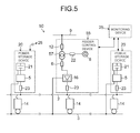
- an electric railcar power feeding system 50 in this embodiment includes a feeder control device 55 in place of the feeder control device 15 included in the electric railcar power feeding system 10 according to the first embodiment.
- the feeder control device 55 includes a transformer 57 in place of the transformer 7 included in the feeder control device 15.
- the electric railcar power feeding system 50 realizes voltage transformation of the alternating-current power supply 9 and voltage transformation of the emergency power supply 8 using one transformer 57 in common for reduction of facilities.
- the transformer 57 transforms the alternating-current power of the alternating-current power supply 9 (the alternating-current power of the first power system) or the power of the emergency power supply 8 (the power of the second power system) so as to output the transformed power for the rectifier 16.
- the transformer 57 includes a tap with a transformation ratio according to the alternating-current power supply 9 and a tap with a transformation ratio according to the emergency power supply 8.
- the transformer 57 employs the latter tap in the independent operation to output the power of the emergency power supply 8 to the rectifier 16 side as illustrated in Fig. 5 . Therefore, according to the electric railcar power feeding system 50, common use of the transformer 57 enables reduction of facilities and cost. Further, the electric railcar power feeding system 50 can perform the voltage transformation of the emergency power supply 8, which cannot be performed by the electric railcar power feeding system 10 in the first embodiment, thereby broadening the options of the employable emergency power supply 8.
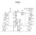
- An electric railcar power feeding system 70 includes a feeder control device 75 in place of the feeder control device 15 included in the electric railcar power feeding system 10 according to the first embodiment.
- the feeder control device 75 includes an emergency power supply 78 in place of the emergency power supply 8 included in the feeder control device 15.
- the transformer 7 and the rectifier 16 are opened by the direct-current circuit breaker 23 in the feeder control device 75 when the alternating-current power supply 9 fails, as in the case of the first embodiment.
- the emergency power supply 78 is connected to the feeder line 2 with no transformer intervening between them and is, for example, a power storage element composed of the number of cells in series corresponding to a DC 1500 V. Accordingly, the battery capacity of the emergency power supply 78 is necessarily large.
- the emergency power supply 78 composed of the power storage element can be made to operate in place of the emergency power supply 8 is in the first embodiment.
- the emergency power supply 78 supplies the main feeder power to the feeder line 2, whereas the power storage device 20 smaller in power storage capacity than the emergency power supply 78 performs compensation for the drop in the feeder line voltage (trolley voltage).
- the emergency power supply 78 having the power storage element may be paralleled-off once from the feeder line 2 when the alternating-current power supply 9 fails.
Landscapes
- Engineering & Computer Science (AREA)
- Mechanical Engineering (AREA)
- Life Sciences & Earth Sciences (AREA)
- Sustainable Development (AREA)
- Sustainable Energy (AREA)
- Power Engineering (AREA)
- Transportation (AREA)
- Charge And Discharge Circuits For Batteries Or The Like (AREA)
- Stand-By Power Supply Arrangements (AREA)
Applications Claiming Priority (1)
| Application Number | Priority Date | Filing Date | Title |
|---|---|---|---|
| JP2013167820A JP5735061B2 (ja) | 2013-08-12 | 2013-08-12 | 電車給電システム |
Publications (2)
| Publication Number | Publication Date |
|---|---|
| EP2837525A2 true EP2837525A2 (fr) | 2015-02-18 |
| EP2837525A3 EP2837525A3 (fr) | 2015-12-02 |
Family
ID=51359270
Family Applications (1)
| Application Number | Title | Priority Date | Filing Date |
|---|---|---|---|
| EP14180226.4A Withdrawn EP2837525A3 (fr) | 2013-08-12 | 2014-08-07 | Système d'alimentation en énergie de wagon électrique, dispositif d'alimentation électrique et dispositif de stockage d'énergie |
Country Status (6)
| Country | Link |
|---|---|
| US (1) | US9873335B2 (fr) |
| EP (1) | EP2837525A3 (fr) |
| JP (1) | JP5735061B2 (fr) |
| CN (1) | CN104369677B (fr) |
| BR (1) | BR102014019747A2 (fr) |
| HK (1) | HK1203176A1 (fr) |
Cited By (4)
| Publication number | Priority date | Publication date | Assignee | Title |
|---|---|---|---|---|
| WO2017060444A1 (fr) * | 2015-10-07 | 2017-04-13 | Abb Schweiz Ag | Agencement et procédé pour transformer une tension |
| RU2636847C1 (ru) * | 2016-08-03 | 2017-11-28 | Илья Александрович Кондрашов | Тяговая подстанция постоянного тока с инерционным накопителем энергии |
| DE102018105300A1 (de) * | 2018-03-08 | 2019-09-12 | Paul Vahle Gmbh & Co. Kg | Gleichstromübertragung über stromschienen |
| WO2023094975A1 (fr) * | 2021-11-23 | 2023-06-01 | Dmowska Andrzejuk Danuta | Procédé et système d'alimentation de traction en cc |
Families Citing this family (24)
| Publication number | Priority date | Publication date | Assignee | Title |
|---|---|---|---|---|
| SG11201805733UA (en) * | 2016-01-20 | 2018-08-30 | Siemens Ag | Vessel energy management system |
| CN105846513A (zh) * | 2016-05-30 | 2016-08-10 | 谢宗洺 | 一种储能型电车成套充电装置 |
| DE102016214051A1 (de) * | 2016-07-29 | 2018-02-01 | Siemens Aktiengesellschaft | Verfahren zur Stromversorgung und Stromversorgung für an einer Bahnstrecke angeordnete Bahnbetriebselemente |
| CN106809031B (zh) * | 2016-09-21 | 2018-01-23 | 比亚迪股份有限公司 | 列车的制动回收系统、用于列车调度的控制中心以及方法 |
| CN106809022B (zh) * | 2016-09-21 | 2018-08-14 | 比亚迪股份有限公司 | 列车的制动回收系统和方法及控制列车运行的控制中心 |
| CN106809025B (zh) * | 2016-09-21 | 2019-02-26 | 比亚迪股份有限公司 | 列车的制动回收系统、用于列车调度的控制中心以及方法 |
| CN106809032B (zh) * | 2016-09-21 | 2019-04-19 | 比亚迪股份有限公司 | 列车的制动回收系统和方法 |
| CN106809024B (zh) * | 2016-09-21 | 2019-04-19 | 比亚迪股份有限公司 | 列车的制动回收系统和方法及列车 |
| CN106809030B (zh) * | 2016-09-21 | 2018-09-07 | 比亚迪股份有限公司 | 列车的制动回收系统、用于列车调度的控制中心以及方法 |
| CN106809027B (zh) * | 2016-09-21 | 2018-12-21 | 比亚迪股份有限公司 | 列车的制动回收系统和方法及列车 |
| CN106809026B (zh) * | 2016-09-21 | 2018-08-14 | 比亚迪股份有限公司 | 列车的制动回收系统和方法、储能电站及控制中心 |
| CN106809029B (zh) * | 2016-09-21 | 2018-09-07 | 比亚迪股份有限公司 | 列车的制动回收系统、用于列车调度的控制中心以及方法 |
| CN106809021B (zh) * | 2016-09-21 | 2018-09-11 | 比亚迪股份有限公司 | 列车的制动回收系统、用于列车调度的控制中心以及方法 |
| CN106809060B (zh) * | 2016-09-21 | 2018-01-23 | 比亚迪股份有限公司 | 轨道交通系统的牵引电源系统及其控制方法 |
| CN106953332B (zh) * | 2017-05-02 | 2019-07-16 | 中国矿业大学 | 基于不控整流和阶梯波合成逆变的电气化铁路同相供电方案 |
| JP6812314B2 (ja) * | 2017-07-21 | 2021-01-13 | 株式会社日立製作所 | 鉄道システムの制御装置及び方法 |
| JP6993803B2 (ja) * | 2017-07-26 | 2022-01-14 | 株式会社東芝 | 電鉄用回生制御システム |
| JP7059627B2 (ja) * | 2017-12-26 | 2022-04-26 | 株式会社Gsユアサ | 鉄道用電力貯蔵装置 |
| JP7059626B2 (ja) * | 2017-12-26 | 2022-04-26 | 株式会社Gsユアサ | 鉄道用電力貯蔵装置 |
| DE102018113250A1 (de) * | 2018-06-04 | 2019-12-05 | Volkswagen Aktiengesellschaft | Oberleitungsanordnung für eine zweipolige Oberleitung |
| CN110676833B (zh) * | 2018-07-02 | 2021-12-07 | 比亚迪股份有限公司 | 轨道能量回馈系统及其控制方法 |
| EP3696009B1 (fr) * | 2019-02-12 | 2024-09-04 | Furrer + Frey AG | Procédé de symétrisation d'un courant triphasé |
| CN110011408B (zh) * | 2019-05-21 | 2024-03-08 | 国网福建省电力有限公司宁德供电公司 | 一种移动应急电源系统及其工作方法 |
| CN113787909B (zh) * | 2021-08-04 | 2023-06-23 | 中车唐山机车车辆有限公司 | 一种供电装置和轨道车辆 |
Family Cites Families (11)
| Publication number | Priority date | Publication date | Assignee | Title |
|---|---|---|---|---|
| JP3964857B2 (ja) | 2003-12-04 | 2007-08-22 | 株式会社日立製作所 | 電鉄用回生電力吸収制御方法 |
| JP4238190B2 (ja) * | 2004-08-26 | 2009-03-11 | 株式会社日立製作所 | 電力貯蔵式回生電力吸収装置およびその制御方法 |
| JP2008022650A (ja) * | 2006-07-13 | 2008-01-31 | Univ Of Tsukuba | 自立運転支援装置及び電源システム |
| CN101965275B (zh) * | 2008-02-29 | 2013-11-06 | 川崎重工业株式会社 | 电气化铁路用电力供给系统 |
| JP5187624B2 (ja) * | 2008-06-30 | 2013-04-24 | 川崎重工業株式会社 | 電気鉄道システムを利用したマイクログリッド |
| JP5331461B2 (ja) | 2008-11-27 | 2013-10-30 | 株式会社東芝 | 鉄道車両駆動システム |
| JP2012105407A (ja) * | 2010-11-08 | 2012-05-31 | Toshiba Corp | 蓄電システム |
| JP5052705B2 (ja) | 2011-01-17 | 2012-10-17 | 三菱電機株式会社 | スイッチング電源装置 |
| JP5377538B2 (ja) * | 2011-02-14 | 2013-12-25 | 株式会社東芝 | 蓄電装置とその設置・運用方法 |
| JP2013018464A (ja) | 2011-07-14 | 2013-01-31 | Kawasaki Heavy Ind Ltd | 蓄電装置を備えた電気鉄道のき電システム |
| US9030852B2 (en) * | 2012-05-31 | 2015-05-12 | General Electric Company | System for power conversion utilizing matrix converters |
-
2013
- 2013-08-12 JP JP2013167820A patent/JP5735061B2/ja active Active
-
2014
- 2014-08-05 US US14/451,701 patent/US9873335B2/en active Active
- 2014-08-07 EP EP14180226.4A patent/EP2837525A3/fr not_active Withdrawn
- 2014-08-08 BR BR102014019747A patent/BR102014019747A2/pt not_active Application Discontinuation
- 2014-08-12 CN CN201410393718.1A patent/CN104369677B/zh active Active
-
2015
- 2015-04-15 HK HK15103679.5A patent/HK1203176A1/xx unknown
Non-Patent Citations (1)
| Title |
|---|
| None |
Cited By (4)
| Publication number | Priority date | Publication date | Assignee | Title |
|---|---|---|---|---|
| WO2017060444A1 (fr) * | 2015-10-07 | 2017-04-13 | Abb Schweiz Ag | Agencement et procédé pour transformer une tension |
| RU2636847C1 (ru) * | 2016-08-03 | 2017-11-28 | Илья Александрович Кондрашов | Тяговая подстанция постоянного тока с инерционным накопителем энергии |
| DE102018105300A1 (de) * | 2018-03-08 | 2019-09-12 | Paul Vahle Gmbh & Co. Kg | Gleichstromübertragung über stromschienen |
| WO2023094975A1 (fr) * | 2021-11-23 | 2023-06-01 | Dmowska Andrzejuk Danuta | Procédé et système d'alimentation de traction en cc |
Also Published As
| Publication number | Publication date |
|---|---|
| JP5735061B2 (ja) | 2015-06-17 |
| CN104369677A (zh) | 2015-02-25 |
| US9873335B2 (en) | 2018-01-23 |
| US20150045997A1 (en) | 2015-02-12 |
| JP2015036280A (ja) | 2015-02-23 |
| CN104369677B (zh) | 2017-06-23 |
| HK1203176A1 (en) | 2015-10-23 |
| EP2837525A3 (fr) | 2015-12-02 |
| BR102014019747A2 (pt) | 2015-09-22 |
Similar Documents
| Publication | Publication Date | Title |
|---|---|---|
| US9873335B2 (en) | Electric railcar power feeding system, power feeding device, and power storage device | |
| KR101715444B1 (ko) | 축전 장치와 그 설치 및 운용 방법 | |
| EP2241472B1 (fr) | Appareil de commande de stockage d'énergie et procédé de véhicule électrique | |
| US9227516B2 (en) | Electric vehicle propulsion control device and railway vehicle system | |
| JP4415874B2 (ja) | 交通システムの充放電方法 | |
| JP3964857B2 (ja) | 電鉄用回生電力吸収制御方法 | |
| KR20100105372A (ko) | 역간 선로 상에 급전 설비를 설치한 철도 시스템 | |
| RU2749439C9 (ru) | Устройство энергоснабжения рельсовых транспортных средств | |
| JP3618273B2 (ja) | 電鉄用直流き電システム | |
| EP3556604B1 (fr) | Dispositif d'alimentation de bâtiment de gare | |
| US10056841B2 (en) | Energy storage arrangement, energy storage system and method for operating an energy storage arrangement | |
| JP5777669B2 (ja) | 電気車用制御装置 | |
| CN101959710B (zh) | 用于有轨车辆的储能器系统 | |
| WO2017104204A1 (fr) | Véhicule | |
| JP6786268B2 (ja) | 蓄電システム | |
| JP5509442B2 (ja) | 電力変換装置及び電気鉄道システム | |
| JP6703913B2 (ja) | 蓄電装置 | |
| JP7301686B2 (ja) | 電力変換システム | |
| JP7301684B2 (ja) | 電力変換システム | |
| JP2006340468A (ja) | 電気車制御装置 | |
| JP2024099375A (ja) | 鉄道車両用の駆動システムおよび駆動方法 | |
| JP2021044980A (ja) | 電力変換システム | |
| JP2013046546A (ja) | 電力変換システム |
Legal Events
| Date | Code | Title | Description |
|---|---|---|---|
| 17P | Request for examination filed |
Effective date: 20140807 |
|
| AK | Designated contracting states |
Kind code of ref document: A2 Designated state(s): AL AT BE BG CH CY CZ DE DK EE ES FI FR GB GR HR HU IE IS IT LI LT LU LV MC MK MT NL NO PL PT RO RS SE SI SK SM TR |
|
| AX | Request for extension of the european patent |
Extension state: BA ME |
|
| PUAI | Public reference made under article 153(3) epc to a published international application that has entered the european phase |
Free format text: ORIGINAL CODE: 0009012 |
|
| PUAL | Search report despatched |
Free format text: ORIGINAL CODE: 0009013 |
|
| AK | Designated contracting states |
Kind code of ref document: A3 Designated state(s): AL AT BE BG CH CY CZ DE DK EE ES FI FR GB GR HR HU IE IS IT LI LT LU LV MC MK MT NL NO PL PT RO RS SE SI SK SM TR |
|
| AX | Request for extension of the european patent |
Extension state: BA ME |
|
| RIC1 | Information provided on ipc code assigned before grant |
Ipc: B60M 3/02 20060101ALN20151026BHEP Ipc: B60M 3/06 20060101AFI20151026BHEP |
|
| RBV | Designated contracting states (corrected) |
Designated state(s): AL AT BE BG CH CY CZ DE DK EE ES FI FR GB GR HR HU IE IS IT LI LT LU LV MC MK MT NL NO PL PT RO RS SE SI SK SM TR |
|
| STAA | Information on the status of an ep patent application or granted ep patent |
Free format text: STATUS: THE APPLICATION HAS BEEN WITHDRAWN |
|
| 18W | Application withdrawn |
Effective date: 20161019 |