EP2836417B1 - Lenkgetriebe - Google Patents
Lenkgetriebe Download PDFInfo
- Publication number
- EP2836417B1 EP2836417B1 EP13717457.9A EP13717457A EP2836417B1 EP 2836417 B1 EP2836417 B1 EP 2836417B1 EP 13717457 A EP13717457 A EP 13717457A EP 2836417 B1 EP2836417 B1 EP 2836417B1
- Authority
- EP
- European Patent Office
- Prior art keywords
- steering gear
- pinion
- outer part
- bushing
- gear according
- Prior art date
- Legal status (The legal status is an assumption and is not a legal conclusion. Google has not performed a legal analysis and makes no representation as to the accuracy of the status listed.)
- Active
Links
Images


Classifications
-
- B—PERFORMING OPERATIONS; TRANSPORTING
- B62—LAND VEHICLES FOR TRAVELLING OTHERWISE THAN ON RAILS
- B62D—MOTOR VEHICLES; TRAILERS
- B62D3/00—Steering gears
- B62D3/02—Steering gears mechanical
-
- B—PERFORMING OPERATIONS; TRANSPORTING
- B62—LAND VEHICLES FOR TRAVELLING OTHERWISE THAN ON RAILS
- B62D—MOTOR VEHICLES; TRAILERS
- B62D3/00—Steering gears
- B62D3/02—Steering gears mechanical
- B62D3/04—Steering gears mechanical of worm type
-
- B—PERFORMING OPERATIONS; TRANSPORTING
- B62—LAND VEHICLES FOR TRAVELLING OTHERWISE THAN ON RAILS
- B62D—MOTOR VEHICLES; TRAILERS
- B62D5/00—Power-assisted or power-driven steering
- B62D5/04—Power-assisted or power-driven steering electrical, e.g. using an electric servo-motor connected to, or forming part of, the steering gear
- B62D5/0409—Electric motor acting on the steering column
-
- B—PERFORMING OPERATIONS; TRANSPORTING
- B62—LAND VEHICLES FOR TRAVELLING OTHERWISE THAN ON RAILS
- B62D—MOTOR VEHICLES; TRAILERS
- B62D5/00—Power-assisted or power-driven steering
- B62D5/04—Power-assisted or power-driven steering electrical, e.g. using an electric servo-motor connected to, or forming part of, the steering gear
- B62D5/0442—Conversion of rotational into longitudinal movement
- B62D5/0454—Worm gears
-
- F—MECHANICAL ENGINEERING; LIGHTING; HEATING; WEAPONS; BLASTING
- F16—ENGINEERING ELEMENTS AND UNITS; GENERAL MEASURES FOR PRODUCING AND MAINTAINING EFFECTIVE FUNCTIONING OF MACHINES OR INSTALLATIONS; THERMAL INSULATION IN GENERAL
- F16H—GEARING
- F16H19/00—Gearings comprising essentially only toothed gears or friction members and not capable of conveying indefinitely-continuing rotary motion
- F16H19/02—Gearings comprising essentially only toothed gears or friction members and not capable of conveying indefinitely-continuing rotary motion for interconverting rotary or oscillating motion and reciprocating motion
-
- F—MECHANICAL ENGINEERING; LIGHTING; HEATING; WEAPONS; BLASTING
- F16—ENGINEERING ELEMENTS AND UNITS; GENERAL MEASURES FOR PRODUCING AND MAINTAINING EFFECTIVE FUNCTIONING OF MACHINES OR INSTALLATIONS; THERMAL INSULATION IN GENERAL
- F16H—GEARING
- F16H55/00—Elements with teeth or friction surfaces for conveying motion; Worms, pulleys or sheaves for gearing mechanisms
- F16H55/02—Toothed members; Worms
- F16H55/22—Toothed members; Worms for transmissions with crossing shafts, especially worms, worm-gears
- F16H55/24—Special devices for taking up backlash
-
- F—MECHANICAL ENGINEERING; LIGHTING; HEATING; WEAPONS; BLASTING
- F16—ENGINEERING ELEMENTS AND UNITS; GENERAL MEASURES FOR PRODUCING AND MAINTAINING EFFECTIVE FUNCTIONING OF MACHINES OR INSTALLATIONS; THERMAL INSULATION IN GENERAL
- F16H—GEARING
- F16H57/00—General details of gearing
- F16H57/02—Gearboxes; Mounting gearing therein
- F16H57/039—Gearboxes for accommodating worm gears
-
- F—MECHANICAL ENGINEERING; LIGHTING; HEATING; WEAPONS; BLASTING
- F16—ENGINEERING ELEMENTS AND UNITS; GENERAL MEASURES FOR PRODUCING AND MAINTAINING EFFECTIVE FUNCTIONING OF MACHINES OR INSTALLATIONS; THERMAL INSULATION IN GENERAL
- F16H—GEARING
- F16H57/00—General details of gearing
- F16H57/12—Arrangements for adjusting or for taking-up backlash not provided for elsewhere
-
- F—MECHANICAL ENGINEERING; LIGHTING; HEATING; WEAPONS; BLASTING
- F16—ENGINEERING ELEMENTS AND UNITS; GENERAL MEASURES FOR PRODUCING AND MAINTAINING EFFECTIVE FUNCTIONING OF MACHINES OR INSTALLATIONS; THERMAL INSULATION IN GENERAL
- F16C—SHAFTS; FLEXIBLE SHAFTS; ELEMENTS OR CRANKSHAFT MECHANISMS; ROTARY BODIES OTHER THAN GEARING ELEMENTS; BEARINGS
- F16C2380/00—Electrical apparatus
- F16C2380/26—Dynamo-electric machines or combinations therewith, e.g. electro-motors and generators
- F16C2380/27—Motor coupled with a gear, e.g. worm gears
-
- F—MECHANICAL ENGINEERING; LIGHTING; HEATING; WEAPONS; BLASTING
- F16—ENGINEERING ELEMENTS AND UNITS; GENERAL MEASURES FOR PRODUCING AND MAINTAINING EFFECTIVE FUNCTIONING OF MACHINES OR INSTALLATIONS; THERMAL INSULATION IN GENERAL
- F16H—GEARING
- F16H57/00—General details of gearing
- F16H57/02—Gearboxes; Mounting gearing therein
- F16H57/021—Shaft support structures, e.g. partition walls, bearing eyes, casing walls or covers with bearings
- F16H2057/0213—Support of worm gear shafts
-
- F—MECHANICAL ENGINEERING; LIGHTING; HEATING; WEAPONS; BLASTING
- F16—ENGINEERING ELEMENTS AND UNITS; GENERAL MEASURES FOR PRODUCING AND MAINTAINING EFFECTIVE FUNCTIONING OF MACHINES OR INSTALLATIONS; THERMAL INSULATION IN GENERAL
- F16H—GEARING
- F16H57/00—General details of gearing
- F16H57/02—Gearboxes; Mounting gearing therein
- F16H57/021—Shaft support structures, e.g. partition walls, bearing eyes, casing walls or covers with bearings
- F16H57/022—Adjustment of gear shafts or bearings
- F16H2057/0222—Lateral adjustment
-
- F—MECHANICAL ENGINEERING; LIGHTING; HEATING; WEAPONS; BLASTING
- F16—ENGINEERING ELEMENTS AND UNITS; GENERAL MEASURES FOR PRODUCING AND MAINTAINING EFFECTIVE FUNCTIONING OF MACHINES OR INSTALLATIONS; THERMAL INSULATION IN GENERAL
- F16H—GEARING
- F16H57/00—General details of gearing
- F16H57/12—Arrangements for adjusting or for taking-up backlash not provided for elsewhere
- F16H2057/126—Self-adjusting during operation, e.g. by a spring
- F16H2057/127—Self-adjusting during operation, e.g. by a spring using springs
-
- Y—GENERAL TAGGING OF NEW TECHNOLOGICAL DEVELOPMENTS; GENERAL TAGGING OF CROSS-SECTIONAL TECHNOLOGIES SPANNING OVER SEVERAL SECTIONS OF THE IPC; TECHNICAL SUBJECTS COVERED BY FORMER USPC CROSS-REFERENCE ART COLLECTIONS [XRACs] AND DIGESTS
- Y10—TECHNICAL SUBJECTS COVERED BY FORMER USPC
- Y10T—TECHNICAL SUBJECTS COVERED BY FORMER US CLASSIFICATION
- Y10T74/00—Machine element or mechanism
- Y10T74/18—Mechanical movements
- Y10T74/18568—Reciprocating or oscillating to or from alternating rotary
- Y10T74/188—Reciprocating or oscillating to or from alternating rotary including spur gear
-
- Y—GENERAL TAGGING OF NEW TECHNOLOGICAL DEVELOPMENTS; GENERAL TAGGING OF CROSS-SECTIONAL TECHNOLOGIES SPANNING OVER SEVERAL SECTIONS OF THE IPC; TECHNICAL SUBJECTS COVERED BY FORMER USPC CROSS-REFERENCE ART COLLECTIONS [XRACs] AND DIGESTS
- Y10—TECHNICAL SUBJECTS COVERED BY FORMER USPC
- Y10T—TECHNICAL SUBJECTS COVERED BY FORMER US CLASSIFICATION
- Y10T74/00—Machine element or mechanism
- Y10T74/19—Gearing
- Y10T74/19623—Backlash take-up
-
- Y—GENERAL TAGGING OF NEW TECHNOLOGICAL DEVELOPMENTS; GENERAL TAGGING OF CROSS-SECTIONAL TECHNOLOGIES SPANNING OVER SEVERAL SECTIONS OF THE IPC; TECHNICAL SUBJECTS COVERED BY FORMER USPC CROSS-REFERENCE ART COLLECTIONS [XRACs] AND DIGESTS
- Y10—TECHNICAL SUBJECTS COVERED BY FORMER USPC
- Y10T—TECHNICAL SUBJECTS COVERED BY FORMER US CLASSIFICATION
- Y10T74/00—Machine element or mechanism
- Y10T74/19—Gearing
- Y10T74/19642—Directly cooperating gears
- Y10T74/19698—Spiral
- Y10T74/19828—Worm
Definitions
- the invention relates to a steering gear and in particular a steering gear for a power steering system of a motor vehicle.
- the known power steering systems are based on a steering gear that translates the drive line of a hydraulic or electric drive and transmits to the steering column.
- Such steering gears are regularly in the form of a fferkylzgetriebes and in particular as fferradgetriebe or worm gear, i. these include a gear wheel which is directly or indirectly connected to the steering rod, as well as a thus driven via a pinion shaft of the drive pinion.
- the pinion shaft is pivotally mounted about an axis which is perpendicular to the longitudinal axis of the pinion shaft and at a distance from the meshing engagement of pinion and gear, and is pressed by means of one or more spring elements against the gear ,
- the pivotability of the pinion shaft is integrated in one of the two bearings, via which the pinion shaft is mounted end.
- This storage is also referred to as "fixed storage”.
- the storage in the region of the other end is then carried out with play (so-called "floating bearing") to allow the deflection caused by the pivoting movement.
- the fixed bearing is regularly provided on the drive side, while the floating bearing is provided at the free end of the pinion shaft.
- the one or more spring elements for pressing the pinion gear to the gear are regularly integrated in the floating bearing.
- a corresponding generic steering system is for example from the WO 2011/073089 A1 known.
- the rolling bearing which receives the pinion shaft in the region of the fixed bearing to store outside in a pivot ring.
- the pivot ring comprises an inner ring which receives the rolling bearing largely free of play and an outer ring which is held largely free of play in a bore of a housing of the steering gear, wherein the outer and the inner ring are connected via a plurality of narrow webs, which in a rotation of the outer ring Inner ring to be twisted.
- a steering gear should be specified that the known from the prior art described, different steering behavior when turning left or right of the steering column, or at least only to a reduced extent.
- This object is solved by the subject matter of the independent claim.
- Advantageous embodiments are the subject of the dependent claims and will become apparent from the following description of the invention.
- the invention is based on the finding that results in the known steering gearbox with gear backlash different steering behavior as a result of oppositely directed moments about the pivot axis of the fixed bearing, which are generated when left or right turning the steering column and the corresponding support rotation of the drive of the power steering system.
- These different moments result from the oppositely directed Gear teeth when turning left or right in conjunction with the lever arm, which results from the distance of the line of action of the toothing forces to the pivot axis.
- the opposite reaction moments about the pivot axis cause in one direction an increase in the force with which the pinion is pressed against the gear, and thus an increase of the friction torque of the transmission, and in the opposite direction a corresponding reduction of the
- the invention is therefore based on the idea to eliminate these oppositely acting moments as possible, but at least to reduce. This is done by making the radial distance between the line of action of the toothing forces and the pivot axis as small as possible and preferably reduced to (substantially) zero. A reduction of this distance (preferably to zero) causes to the same extent a reduction (elimination) of the reaction moments.
- the different steering behavior known from the prior art when turning left or right can thereby be reduced or completely avoided.
- a generic steering gear with a gear, a meshing pinion and a pinion shaft comprising the pinion, which is pivotable about a transverse axis to the longitudinal axis of the pinion shaft pivot axis is accordingly further developed according to the invention that the radial distance (relative to the pinion shaft or the gear) between the pivot axis and the meshing engagement as small as possible, but at least smaller than the core radius of the pinion (ie, the radial distance between the longitudinal axis of the pinion shaft and the tooth root of the pinion) is.
- this distance is substantially zero, whereby the emergence of the different steering behavior causing reaction moments can be completely avoided.
- tooth engagement is understood to mean the tangential plane at the point of contact of the partial or rolling circles of the pinion and the toothed wheel.
- a (first) socket may be provided which has (at least) one (preferably annular) outer part and (at least) one (preferably annular) inner part, which is arranged within the outer part, wherein the outer part and the inner part for forming the pivot axis via at least one, a relative rotation of outer part to inner part permitting web are connected.
- the web can for this purpose preferably be deformable and in particular elastically deformable, so that it has the effect of a Torsionsfederstabs.
- a Torsionsfederstabs not only the pivot axis in the (first) socket can be realized in a simple manner, but also elastic restoring forces can be generated via which a pressing of the pinion to the gear can be realized with the goal of the gear play compensation.
- the web (the integrated into the housing of the steering gear bushing) is twisted.
- the wear on the gear and pinion i. E.
- the backlash tends to increase over the life of the steering gear.
- this requires an over the life reinforced gear backlash compensation.
- the elastic deflection and thus the bias of the gear play compensation effecting spring element should be relatively large in a new steering gear.
- the outer part is rotated relative to the inner part of the socket to a sufficient extent and that this rotation in the zu expected maximum gear play not reduced to zero as possible.
- the longitudinal axis of the pinion shaft in the new condition of the steering gear includes a defined pivot angle with the toothing plane.
- a receptacle for the fixed bearing in the housing of the steering gear may be provided to position a receptacle for the fixed bearing in the housing of the steering gear so relative to the gear that results in this pivoting angle geometrically with non-worn gear and pinion.
- it may be provided to realize a radial offset of the longitudinal axis of the pinion shaft in the region of the fixed bearing from the center axis of the toothed wheel, from which the defined pivot angle results, via a non-concentric position of the outer part and the inner part of the (first) bushing.
- a (second) socket as part of a movable bearing, which causes a deflection of the free end of the pinion shaft as a result of pivoting about in the fixed bearing pivot axis allows.
- the (second) bush (at least) has an outer part and (at least) an inner part, wherein the outer part and the inner part are connected to each other, that in at least one radial direction (relative to the pinion shaft) to each other are.
- the outer part and the inner part of the (second) bush of the movable bearing are preferably (as well as those of the (first) bush of the fixed bearing (circular) annular. This allows in combination with the formed in the (first) bushing of the fixed bearing radial offset the production of the two recordings in the housing of the steering gear in a single operation by means of a cutting acting tool, despite the provided for the function of the gear backlash offset of the central axes of the fixed bearing and the floating bearing the two shots can be arranged concentrically.
- Forming the (second) bushing of the movable bearing as a coherent unit, which nevertheless allows the desired radial displaceability from outer part to inner part, can provide that the outer part and the inner part are connected to each other via (at least) one joint.
- the bearing of the free end of the pinion shaft should be as free of play as possible to an entanglement of the pinion on the gear avoid.
- the distance between the outer part and the inner part in the section radially opposite the joint is as small as possible, but preferably not zero. For example, a distance of only about 0.1 mm may be provided.
- the joint may preferably be formed by contacting a portion of the outer part and a portion of the inner part in the area of the joint, wherein these sections of outer and inner part of a shell of a highly elastic material (eg an elastomer) are surrounded.
- the joint movement is then made possible by a sliding or rolling of the sections of the outer and inner parts, while the sheath on the one hand hardly hindered this joint movement and on the other hand ensures the cohesion of outer part and inner part.
- the (second) bushing of the movable bearing can preferably be provided that adjusts the intended small distance in the hinge radially opposite portion of the socket only during assembly of the socket in the housing.
- This can preferably be achieved in that the outer part and / or the inner part in the relevant portion has a radially displaceable limiting element, whose radial width is also preferably greater than the radial width of the corresponding portion of the outer part or of the inner part.
- the limiting element at a not mounted in the housing of the steering gear (or on the pinion shaft) mounted (second) bushing of the movable bearing radially outward (or inward) is shifted so that one for the production and Mounting the sleeve advantageously relatively large distance from the inner part to the limiting element sets.
- the limiting element may protrude beyond the outer surface of the outer part (or the inner surface of the inner part) due to its relatively large radial width.
- This projection of the limiting element is not possible in the assembled state of the (second) socket of the movable bearing due to a collision with the receptacle of the housing (or the pinion shaft).
- the fastener must therefore be moved radially inwards (or outwards) for mounting and is fixed in this position, in which this forms the desired small distance with the inner ring of the receptacle of the housing (or the pinion shaft).
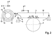
- the Fig. 1 shows the essential components of an embodiment of a steering gear according to the invention.
- This comprises a housing 1, within which a gear 2 and a meshing with the gear 2 pinion 3 are mounted.
- Pinion 3 and a pinion shaft comprising the pinion are integrally formed in the form of a worm.
- the gear 2 is fixedly mounted on a steering column 4 of a motor vehicle.
- the pinion 3 has a drive-side end via which it is connectable to the output shaft of an unillustrated drive (e.g., electric motor).
- an unillustrated drive e.g., electric motor
- the pinion 3 is mounted in the housing by means of a first bearing.
- This bearing is designed as a fixed bearing 5, which permits substantially no translation of the pinion 3 relative to the housing 1, but a pivoting about a pivot axis 6.
- This pivoting causes a deflection of the drive end opposite end free end of the pinion 3, which is mounted there by means of a movable bearing 7 in a corresponding receptacle of the housing 1.
- This floating bearing 7 is designed so that it allows the resulting from the pivoting of the pinion 3 deflection of the free end.
- Both the fixed bearing 5 and the floating bearing 7 each comprise a rolling bearing 8, 9, in which the corresponding portion of the pinion 3 is mounted largely free of play.
- the Rolling 8, 9 themselves are each mounted in a socket 10, 11, which in turn is arranged largely free of play in a corresponding receptacle of the housing 1.
- the bushes 10, 11 are structurally designed so that - in the case of the fixed bearing 5 - allow the pivoting of the pinion 3 about the pivot axis 6 and - in the case of the movable bearing 7 - the deflection of the free end of the pinion 3.
- the bush 10 of the fixed bearing 5 comprises an outer part in the form of an outer ring 12 (for example made of spring steel) and an inner part in the form of an inner ring 13 (for example made of spring steel).
- the outer ring 12 is connected via two webs 14 (eg made of spring steel) to the inner ring 13, wherein the two webs 14 are substantially collinear and thereby form the pivot axis 6, about which the outer ring 12 can be pivoted relative to the inner ring 13.
- the webs 14 and thus the pivot axis 6 do not extend through the center of the sleeve 10, but radially offset thereto (see. Fig. 2 and 3 ).
- the pivot axis thus does not cross the longitudinal axis 16 of the pinion. 3
- the pivot axis 6 is within the tangential plane, which is formed in the point of contact of the two partial or rolling circles of gear 2 and pinion 3 (tooth engagement 15), as shown in of the Fig. 2 is shown schematically.
- the housing 1 has for this purpose a corresponding mating contour.
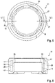
- FIGS. 5 and 6 show the bush which forms part of the arranged in the region of the free end of the screw 3 movable bearing 7.
- An essential function of this bush 11 is to allow the translational movement (deflection) of the free end of the screw 3 as a result of their pivoting about the pivot axis 6 formed in the fixed bearing 5.
- the bush 11 likewise comprises an outer part in the form of an outer ring 17 and an inner part in the form of an inner ring 18.
- the inner ring 18 is arranged concentrically within the outer ring 17 at a substantially constant distance. In one section, the inner ring 18 is connected to the outer ring 17 via a radially extending web 19.
- the inner ring 18 of the bushing 11 of the movable bearing 7 also has a collar 24. This serves in conjunction with the roller bearing 9 of the axial positioning of the bush 11 in the housing first
- the distance between the inner ring 18 and the outer ring 17 in the web 19 radially opposite portion of the bushing 11 is limited to a small amount of, for example, 0.1 mm.
- the limiting element 21 has a radial width which is greater than the radial width of the outer ring 17.
- the limiting element 21 of the bushing 11, which has not yet been mounted in the housing 1 can be displaced outwards so far that it projects beyond the outer surface of the outer ring 17.
- a relatively large distance between the outer side of the inner ring 18 and the limiting element 21 is established. This distance is reduced during assembly of the bushing 11 in the housing 1 to the desired level, since then an overhanging of the outer surface of the outer ring 17 by the limiting element 21 due to a collision with the housing 1 is no longer possible.
- the outer ring 17 of the bush 11 further comprises a stop element 22, that a movement of the inner ring 18 in a pivoting of the screw up in the Fig. 1 and 2 limited.
- the steering gear according to the invention causes a compensation of a backlash, as it can be adjusted in particular by manufacturing tolerances of the components of the steering gear, by different thermal expansions of these components and by wear.
- This gear play compensation is achieved in that the pinion 3 is pivotally mounted and spring-loaded against the gear 2 is pressed.
- the spring load is - as well as the formation of the pivot axis 6 - realized by the webs 14 of the bushing 10 of the fixed bearing 5, which are twisted due to the relative rotation of the outer ring 12 to inner ring 13 and thus functionally act as a torsion spring bar.
- the pinion 3 in the new production of the steering gear with a relatively large pivoting angle.
- it is provided to integrate the pinion 3 in the housing 1 such that its longitudinal axis 16 in the region of the fixed bearing 5 has a slightly smaller distance from the toothing engagement or the line of action 15 of the toothing forces (F a1 , F a2 ) than in the Area of the floating bearing 7 is the case (see. Fig. 1 ).
- This offset is made by a corresponding Offset (x) of the inner ring 12 reaches the outer ring 13 of the bush 10 of the fixed bearing 5; these are therefore not arranged exactly concentric (see. 3 and 4 ).
- This makes it possible to arrange the fixed bearing 5 and the floating bearing 7 despite the intended offset (x) in recordings of the housing 1, which are themselves concentric. Thereby, the production of the housing 1 can be simplified.
Landscapes
- Engineering & Computer Science (AREA)
- General Engineering & Computer Science (AREA)
- Mechanical Engineering (AREA)
- Chemical & Material Sciences (AREA)
- Combustion & Propulsion (AREA)
- Transportation (AREA)
- Gear Transmission (AREA)
- Power Steering Mechanism (AREA)
Applications Claiming Priority (2)
| Application Number | Priority Date | Filing Date | Title |
|---|---|---|---|
| DE102012103146A DE102012103146A1 (de) | 2012-04-12 | 2012-04-12 | Lenkgetriebe |
| PCT/EP2013/057172 WO2013152995A1 (de) | 2012-04-12 | 2013-04-05 | Lenkgetriebe |
Publications (2)
| Publication Number | Publication Date |
|---|---|
| EP2836417A1 EP2836417A1 (de) | 2015-02-18 |
| EP2836417B1 true EP2836417B1 (de) | 2016-06-29 |
Family
ID=48142741
Family Applications (1)
| Application Number | Title | Priority Date | Filing Date |
|---|---|---|---|
| EP13717457.9A Active EP2836417B1 (de) | 2012-04-12 | 2013-04-05 | Lenkgetriebe |
Country Status (6)
| Country | Link |
|---|---|
| US (1) | US9216760B2 (zh) |
| EP (1) | EP2836417B1 (zh) |
| CN (1) | CN104321239B (zh) |
| DE (1) | DE102012103146A1 (zh) |
| HU (1) | HUE030457T2 (zh) |
| WO (1) | WO2013152995A1 (zh) |
Cited By (8)
| Publication number | Priority date | Publication date | Assignee | Title |
|---|---|---|---|---|
| DE102016121394A1 (de) | 2016-11-09 | 2018-05-09 | Robert Bosch Gmbh | Festlager, Lenkgetriebe und Lenksystem |
| DE102016121393A1 (de) | 2016-11-09 | 2018-05-09 | Robert Bosch Gmbh | Kugellager und Verfahren zu dessen Herstellung, Festlager, Lenkgetriebe und Lenksystem |
| DE102016121412A1 (de) | 2016-11-09 | 2018-05-09 | Robert Bosch Gmbh | Festlager und Lenkgetriebe |
| WO2018206305A1 (de) | 2017-05-08 | 2018-11-15 | Robert Bosch Gmbh | Festlager, lenkgetriebe und lenksystem |
| DE102017209563A1 (de) | 2017-06-07 | 2018-12-13 | Robert Bosch Gmbh | Loslager, Lenkgetriebe und Lenksystem |
| WO2019101431A1 (de) * | 2017-11-23 | 2019-05-31 | Robert Bosch Gmbh | Verfahren zur herstellung eines lenkgetriebes |
| WO2019134814A1 (de) | 2018-01-04 | 2019-07-11 | Robert Bosch Gmbh | Lenkgetriebe für ein kraftfahrzeug |
| DE102020214844A1 (de) | 2020-11-26 | 2022-06-02 | Robert Bosch Gesellschaft mit beschränkter Haftung | Lenksystem für ein Kraftfahrzeug |
Families Citing this family (16)
| Publication number | Priority date | Publication date | Assignee | Title |
|---|---|---|---|---|
| DE102013104521A1 (de) | 2013-05-03 | 2014-11-20 | Zf Lenksysteme Gmbh | Lenkgetriebe |
| DE102014105921A1 (de) | 2014-04-28 | 2015-10-29 | Thyssenkrupp Presta Ag | Vorrichtung zum Aufbringen einer Hilfskraft in einer Kraftfahrzeuglenkung |
| DE102014110306A1 (de) * | 2014-07-22 | 2016-01-28 | Thyssenkrupp Ag | Elektromechanische Servolenkung |
| GB201504960D0 (en) * | 2015-03-24 | 2015-05-06 | Trw Ltd | A gearbox assembly for an electric power steering assembly |
| GB201504958D0 (en) * | 2015-03-24 | 2015-05-06 | Trw Ltd | A gearbox assembly for an electric power steering assembly |
| DE102016104150A1 (de) | 2016-03-08 | 2017-09-14 | Robert Bosch Automotive Steering Gmbh | Lenkgetriebe |
| KR102591716B1 (ko) * | 2016-10-31 | 2023-10-23 | 현대모비스 주식회사 | 전동식 조향장치 |
| DE102016122378A1 (de) * | 2016-11-21 | 2018-05-24 | Robert Bosch Gmbh | Lenksystem |
| DE102017215955A1 (de) | 2017-09-11 | 2019-03-14 | Robert Bosch Gmbh | Festlager für ein Lenkgetriebe und Verfahren zur Herstellung des Festlagers |
| DE102017218853A1 (de) * | 2017-10-23 | 2019-04-25 | Robert Bosch Gmbh | Lenkgetriebe und Verfahren zur Herstellung des Lenkgetriebes |
| CN107631009B (zh) * | 2017-11-07 | 2022-07-29 | 中材建设有限公司 | 适应大齿轮偏摆的啮合传动装置 |
| DE102017220609A1 (de) | 2017-11-17 | 2019-05-23 | Robert Bosch Gmbh | Verfahren zur Herstellung einer Lagervorrichtung für ein Festlager eines Lenkgetriebes eines Kraftfahrzeugs |
| US10906578B2 (en) * | 2017-12-29 | 2021-02-02 | Steering Solutions Ip Holding Corporation | Power actuator assembly for steering column assemblies |
| DE102018201858A1 (de) | 2018-02-07 | 2019-08-29 | Robert Bosch Gmbh | Lenkgetriebe, Lenksystem und Verfahren zur Herstellung eines Schwenkrings für ein Lenkgetriebe |
| CN109780054A (zh) * | 2019-01-28 | 2019-05-21 | 宁波易锐汽车零部件有限公司 | 一种塑料轴承衬套及其制造方法 |
| CN114198461B (zh) * | 2021-11-01 | 2024-03-08 | 科德数控股份有限公司 | 一种径向齿轮消隙结构 |
Family Cites Families (7)
| Publication number | Priority date | Publication date | Assignee | Title |
|---|---|---|---|---|
| FR2808759B1 (fr) * | 2000-05-10 | 2005-08-26 | Koyo Seiko Co | Appareil de direction assistee electrique |
| CN100476241C (zh) * | 2003-06-25 | 2009-04-08 | 日本精工株式会社 | 蜗轮减速器及电动式动力转向装置 |
| US20090314114A1 (en) * | 2008-06-18 | 2009-12-24 | Elram Engineering And Advanced Technologies 1992 Ltd. | Backlash elimination mechanism for gear systems for low speed applications |
| DE102009002940A1 (de) | 2009-05-08 | 2010-11-11 | Zf Lenksysteme Gmbh | Lagerung einer Schnecke in einem Lenkgetriebe |
| DE102009054655A1 (de) | 2009-12-15 | 2011-06-16 | Zf Lenksysteme Gmbh | Lenkgetriebe mit Festlager und Loslager für Schraubritzel |
| JP5641195B2 (ja) * | 2010-04-13 | 2014-12-17 | 株式会社ジェイテクト | 電動パワーステアリング装置 |
| FR2972514B1 (fr) * | 2011-03-09 | 2013-09-06 | Skf Ab | Dispositif de compensation d'usure pour engrenage. |
-
2012
- 2012-04-12 DE DE102012103146A patent/DE102012103146A1/de not_active Withdrawn
-
2013
- 2013-04-05 WO PCT/EP2013/057172 patent/WO2013152995A1/de active Application Filing
- 2013-04-05 HU HUE13717457A patent/HUE030457T2/en unknown
- 2013-04-05 EP EP13717457.9A patent/EP2836417B1/de active Active
- 2013-04-05 CN CN201380019225.5A patent/CN104321239B/zh active Active
- 2013-04-05 US US14/387,344 patent/US9216760B2/en active Active
Non-Patent Citations (1)
| Title |
|---|
| None * |
Cited By (12)
| Publication number | Priority date | Publication date | Assignee | Title |
|---|---|---|---|---|
| DE102016121394A1 (de) | 2016-11-09 | 2018-05-09 | Robert Bosch Gmbh | Festlager, Lenkgetriebe und Lenksystem |
| DE102016121393A1 (de) | 2016-11-09 | 2018-05-09 | Robert Bosch Gmbh | Kugellager und Verfahren zu dessen Herstellung, Festlager, Lenkgetriebe und Lenksystem |
| DE102016121412A1 (de) | 2016-11-09 | 2018-05-09 | Robert Bosch Gmbh | Festlager und Lenkgetriebe |
| WO2018086782A1 (de) | 2016-11-09 | 2018-05-17 | Robert Bosch Gmbh | Festlager und lenkgetriebe |
| US11661098B2 (en) | 2016-11-09 | 2023-05-30 | Robert Bosch Gmbh | Fixed bearing and steering gear |
| WO2018206305A1 (de) | 2017-05-08 | 2018-11-15 | Robert Bosch Gmbh | Festlager, lenkgetriebe und lenksystem |
| DE102017209563A1 (de) | 2017-06-07 | 2018-12-13 | Robert Bosch Gmbh | Loslager, Lenkgetriebe und Lenksystem |
| WO2018224248A1 (de) | 2017-06-07 | 2018-12-13 | Robert Bosch Gmbh | Loslager, lenkgetriebe und lenksystem |
| US11524714B2 (en) | 2017-06-07 | 2022-12-13 | Robert Bosch Gmbh | Floating bearing, steering gear, and steering system |
| WO2019101431A1 (de) * | 2017-11-23 | 2019-05-31 | Robert Bosch Gmbh | Verfahren zur herstellung eines lenkgetriebes |
| WO2019134814A1 (de) | 2018-01-04 | 2019-07-11 | Robert Bosch Gmbh | Lenkgetriebe für ein kraftfahrzeug |
| DE102020214844A1 (de) | 2020-11-26 | 2022-06-02 | Robert Bosch Gesellschaft mit beschränkter Haftung | Lenksystem für ein Kraftfahrzeug |
Also Published As
| Publication number | Publication date |
|---|---|
| WO2013152995A1 (de) | 2013-10-17 |
| DE102012103146A1 (de) | 2013-10-17 |
| US9216760B2 (en) | 2015-12-22 |
| CN104321239A (zh) | 2015-01-28 |
| CN104321239B (zh) | 2016-08-24 |
| US20150040699A1 (en) | 2015-02-12 |
| EP2836417A1 (de) | 2015-02-18 |
| HUE030457T2 (en) | 2017-05-29 |
Similar Documents
| Publication | Publication Date | Title |
|---|---|---|
| EP2836417B1 (de) | Lenkgetriebe | |
| EP2836416B1 (de) | Loslager für ein lenkgetriebe | |
| DE102016000023B4 (de) | Kraftfahrzeug-Reduziereinrichtung | |
| DE69913345T2 (de) | Elektrische servolenkung | |
| EP2994362B1 (de) | Anfederungs-exzenterschwinge in ceps-anwendung | |
| WO2011104217A1 (de) | Schraubradgetriebe für eine lenkung eines kraftfahrzeugs | |
| EP2345569B1 (de) | Schraubradgetriebe für eine Lenkung eines Kraftfahrzeugs | |
| DE102014107073A1 (de) | Lenkgetriebe | |
| DE102013213708A1 (de) | Schneckengetriebe für eine Lenkhilfevorrichtung eines Kraftfahrzeuges mit Spielausgleich | |
| EP3544878A1 (de) | Lenkgetriebe und lenksystem | |
| DE102019125310A1 (de) | Planetenwälzgetriebe | |
| EP3426541B1 (de) | Lenkgetriebe | |
| WO2018091200A1 (de) | Lenksystem | |
| EP3538418B1 (de) | Festlager und lenkgetriebe | |
| DE102009058378B4 (de) | KFZ-Getriebe umfassend eine Verzahnungsanordnung mit radialer Verspannung | |
| DE102012103857A1 (de) | Vorrichtung zum Andrücken einer Schnecke oder eines Schraubritzels an ein Schneckenrad oder an ein Schraubrad | |
| EP2517946B1 (de) | Zahnstangen-Lenkgetriebe für ein Fahrzeug | |
| DE102020214844A1 (de) | Lenksystem für ein Kraftfahrzeug | |
| EP2640623B1 (de) | Rollengelagerte zahnstangenführung | |
| DE102019207614A1 (de) | Lenkgetriebe für ein Kraftfahrzeug | |
| EP3691957B1 (de) | Elektromechanische servolenkung mit schraubradgetriebe und einer kompensationseinrichtung zur abstützung eines loslagers am getriebegehäuse | |
| DE102022114373B3 (de) | Kopplungseinheit zum Koppeln und Entkoppeln zweier Antriebselemente eines Antriebsstrangs | |
| DE102022114776B3 (de) | Kopplungseinheit zur reversiblen Kopplung einer Antriebsseite mit einer Abtriebsseite eines Antriebsstrangs | |
| DE102017212070A1 (de) | Zahnstangengetriebe für ein Kraftfahrzeug | |
| DE102019219125A1 (de) | Lagervorrichtung für ein Festlager und Lenkgetriebe |
Legal Events
| Date | Code | Title | Description |
|---|---|---|---|
| PUAI | Public reference made under article 153(3) epc to a published international application that has entered the european phase |
Free format text: ORIGINAL CODE: 0009012 |
|
| 17P | Request for examination filed |
Effective date: 20140828 |
|
| AK | Designated contracting states |
Kind code of ref document: A1 Designated state(s): AL AT BE BG CH CY CZ DE DK EE ES FI FR GB GR HR HU IE IS IT LI LT LU LV MC MK MT NL NO PL PT RO RS SE SI SK SM TR |
|
| AX | Request for extension of the european patent |
Extension state: BA ME |
|
| RAP1 | Party data changed (applicant data changed or rights of an application transferred) |
Owner name: FUECHSEL, DENNIS Owner name: ROBERT BOSCH AUTOMOTIVE STEERING GMBH Owner name: HAFERMALZ, JENS |
|
| RAP1 | Party data changed (applicant data changed or rights of an application transferred) |
Owner name: ROBERT BOSCH AUTOMOTIVE STEERING GMBH |
|
| DAX | Request for extension of the european patent (deleted) | ||
| GRAP | Despatch of communication of intention to grant a patent |
Free format text: ORIGINAL CODE: EPIDOSNIGR1 |
|
| INTG | Intention to grant announced |
Effective date: 20160229 |
|
| GRAS | Grant fee paid |
Free format text: ORIGINAL CODE: EPIDOSNIGR3 |
|
| GRAA | (expected) grant |
Free format text: ORIGINAL CODE: 0009210 |
|
| AK | Designated contracting states |
Kind code of ref document: B1 Designated state(s): AL AT BE BG CH CY CZ DE DK EE ES FI FR GB GR HR HU IE IS IT LI LT LU LV MC MK MT NL NO PL PT RO RS SE SI SK SM TR |
|
| REG | Reference to a national code |
Ref country code: GB Ref legal event code: FG4D Free format text: NOT ENGLISH |
|
| REG | Reference to a national code |
Ref country code: CH Ref legal event code: EP |
|
| REG | Reference to a national code |
Ref country code: AT Ref legal event code: REF Ref document number: 808855 Country of ref document: AT Kind code of ref document: T Effective date: 20160715 |
|
| REG | Reference to a national code |
Ref country code: IE Ref legal event code: FG4D Free format text: LANGUAGE OF EP DOCUMENT: GERMAN |
|
| REG | Reference to a national code |
Ref country code: DE Ref legal event code: R096 Ref document number: 502013003546 Country of ref document: DE |
|
| REG | Reference to a national code |
Ref country code: LT Ref legal event code: MG4D |
|
| PG25 | Lapsed in a contracting state [announced via postgrant information from national office to epo] |
Ref country code: FI Free format text: LAPSE BECAUSE OF FAILURE TO SUBMIT A TRANSLATION OF THE DESCRIPTION OR TO PAY THE FEE WITHIN THE PRESCRIBED TIME-LIMIT Effective date: 20160629 Ref country code: NO Free format text: LAPSE BECAUSE OF FAILURE TO SUBMIT A TRANSLATION OF THE DESCRIPTION OR TO PAY THE FEE WITHIN THE PRESCRIBED TIME-LIMIT Effective date: 20160929 Ref country code: LT Free format text: LAPSE BECAUSE OF FAILURE TO SUBMIT A TRANSLATION OF THE DESCRIPTION OR TO PAY THE FEE WITHIN THE PRESCRIBED TIME-LIMIT Effective date: 20160629 |
|
| REG | Reference to a national code |
Ref country code: NL Ref legal event code: MP Effective date: 20160629 |
|
| PG25 | Lapsed in a contracting state [announced via postgrant information from national office to epo] |
Ref country code: NL Free format text: LAPSE BECAUSE OF FAILURE TO SUBMIT A TRANSLATION OF THE DESCRIPTION OR TO PAY THE FEE WITHIN THE PRESCRIBED TIME-LIMIT Effective date: 20160629 Ref country code: SE Free format text: LAPSE BECAUSE OF FAILURE TO SUBMIT A TRANSLATION OF THE DESCRIPTION OR TO PAY THE FEE WITHIN THE PRESCRIBED TIME-LIMIT Effective date: 20160629 Ref country code: LV Free format text: LAPSE BECAUSE OF FAILURE TO SUBMIT A TRANSLATION OF THE DESCRIPTION OR TO PAY THE FEE WITHIN THE PRESCRIBED TIME-LIMIT Effective date: 20160629 Ref country code: GR Free format text: LAPSE BECAUSE OF FAILURE TO SUBMIT A TRANSLATION OF THE DESCRIPTION OR TO PAY THE FEE WITHIN THE PRESCRIBED TIME-LIMIT Effective date: 20160930 Ref country code: RS Free format text: LAPSE BECAUSE OF FAILURE TO SUBMIT A TRANSLATION OF THE DESCRIPTION OR TO PAY THE FEE WITHIN THE PRESCRIBED TIME-LIMIT Effective date: 20160629 Ref country code: HR Free format text: LAPSE BECAUSE OF FAILURE TO SUBMIT A TRANSLATION OF THE DESCRIPTION OR TO PAY THE FEE WITHIN THE PRESCRIBED TIME-LIMIT Effective date: 20160629 |
|
| PG25 | Lapsed in a contracting state [announced via postgrant information from national office to epo] |
Ref country code: CZ Free format text: LAPSE BECAUSE OF FAILURE TO SUBMIT A TRANSLATION OF THE DESCRIPTION OR TO PAY THE FEE WITHIN THE PRESCRIBED TIME-LIMIT Effective date: 20160629 Ref country code: IT Free format text: LAPSE BECAUSE OF FAILURE TO SUBMIT A TRANSLATION OF THE DESCRIPTION OR TO PAY THE FEE WITHIN THE PRESCRIBED TIME-LIMIT Effective date: 20160629 Ref country code: RO Free format text: LAPSE BECAUSE OF FAILURE TO SUBMIT A TRANSLATION OF THE DESCRIPTION OR TO PAY THE FEE WITHIN THE PRESCRIBED TIME-LIMIT Effective date: 20160629 Ref country code: SK Free format text: LAPSE BECAUSE OF FAILURE TO SUBMIT A TRANSLATION OF THE DESCRIPTION OR TO PAY THE FEE WITHIN THE PRESCRIBED TIME-LIMIT Effective date: 20160629 Ref country code: EE Free format text: LAPSE BECAUSE OF FAILURE TO SUBMIT A TRANSLATION OF THE DESCRIPTION OR TO PAY THE FEE WITHIN THE PRESCRIBED TIME-LIMIT Effective date: 20160629 Ref country code: IS Free format text: LAPSE BECAUSE OF FAILURE TO SUBMIT A TRANSLATION OF THE DESCRIPTION OR TO PAY THE FEE WITHIN THE PRESCRIBED TIME-LIMIT Effective date: 20161029 |
|
| PG25 | Lapsed in a contracting state [announced via postgrant information from national office to epo] |
Ref country code: SM Free format text: LAPSE BECAUSE OF FAILURE TO SUBMIT A TRANSLATION OF THE DESCRIPTION OR TO PAY THE FEE WITHIN THE PRESCRIBED TIME-LIMIT Effective date: 20160629 Ref country code: PL Free format text: LAPSE BECAUSE OF FAILURE TO SUBMIT A TRANSLATION OF THE DESCRIPTION OR TO PAY THE FEE WITHIN THE PRESCRIBED TIME-LIMIT Effective date: 20160629 Ref country code: ES Free format text: LAPSE BECAUSE OF FAILURE TO SUBMIT A TRANSLATION OF THE DESCRIPTION OR TO PAY THE FEE WITHIN THE PRESCRIBED TIME-LIMIT Effective date: 20160629 Ref country code: PT Free format text: LAPSE BECAUSE OF FAILURE TO SUBMIT A TRANSLATION OF THE DESCRIPTION OR TO PAY THE FEE WITHIN THE PRESCRIBED TIME-LIMIT Effective date: 20161031 |
|
| REG | Reference to a national code |
Ref country code: DE Ref legal event code: R097 Ref document number: 502013003546 Country of ref document: DE |
|
| REG | Reference to a national code |
Ref country code: FR Ref legal event code: PLFP Year of fee payment: 5 |
|
| REG | Reference to a national code |
Ref country code: HU Ref legal event code: AG4A Ref document number: E030457 Country of ref document: HU |
|
| PG25 | Lapsed in a contracting state [announced via postgrant information from national office to epo] |
Ref country code: DK Free format text: LAPSE BECAUSE OF FAILURE TO SUBMIT A TRANSLATION OF THE DESCRIPTION OR TO PAY THE FEE WITHIN THE PRESCRIBED TIME-LIMIT Effective date: 20160629 |
|
| 26N | No opposition filed |
Effective date: 20170330 |
|
| PLBE | No opposition filed within time limit |
Free format text: ORIGINAL CODE: 0009261 |
|
| STAA | Information on the status of an ep patent application or granted ep patent |
Free format text: STATUS: NO OPPOSITION FILED WITHIN TIME LIMIT |
|
| PG25 | Lapsed in a contracting state [announced via postgrant information from national office to epo] |
Ref country code: SI Free format text: LAPSE BECAUSE OF FAILURE TO SUBMIT A TRANSLATION OF THE DESCRIPTION OR TO PAY THE FEE WITHIN THE PRESCRIBED TIME-LIMIT Effective date: 20160629 Ref country code: BG Free format text: LAPSE BECAUSE OF FAILURE TO SUBMIT A TRANSLATION OF THE DESCRIPTION OR TO PAY THE FEE WITHIN THE PRESCRIBED TIME-LIMIT Effective date: 20160929 |
|
| REG | Reference to a national code |
Ref country code: CH Ref legal event code: PL |
|
| GBPC | Gb: european patent ceased through non-payment of renewal fee |
Effective date: 20170405 |
|
| REG | Reference to a national code |
Ref country code: IE Ref legal event code: MM4A |
|
| PG25 | Lapsed in a contracting state [announced via postgrant information from national office to epo] |
Ref country code: MC Free format text: LAPSE BECAUSE OF FAILURE TO SUBMIT A TRANSLATION OF THE DESCRIPTION OR TO PAY THE FEE WITHIN THE PRESCRIBED TIME-LIMIT Effective date: 20160629 |
|
| PG25 | Lapsed in a contracting state [announced via postgrant information from national office to epo] |
Ref country code: LI Free format text: LAPSE BECAUSE OF NON-PAYMENT OF DUE FEES Effective date: 20170430 Ref country code: LU Free format text: LAPSE BECAUSE OF NON-PAYMENT OF DUE FEES Effective date: 20170405 Ref country code: GB Free format text: LAPSE BECAUSE OF NON-PAYMENT OF DUE FEES Effective date: 20170405 Ref country code: CH Free format text: LAPSE BECAUSE OF NON-PAYMENT OF DUE FEES Effective date: 20170430 |
|
| REG | Reference to a national code |
Ref country code: BE Ref legal event code: MM Effective date: 20170430 |
|
| REG | Reference to a national code |
Ref country code: FR Ref legal event code: PLFP Year of fee payment: 6 |
|
| PG25 | Lapsed in a contracting state [announced via postgrant information from national office to epo] |
Ref country code: IE Free format text: LAPSE BECAUSE OF NON-PAYMENT OF DUE FEES Effective date: 20170405 |
|
| PG25 | Lapsed in a contracting state [announced via postgrant information from national office to epo] |
Ref country code: BE Free format text: LAPSE BECAUSE OF NON-PAYMENT OF DUE FEES Effective date: 20170430 |
|
| PG25 | Lapsed in a contracting state [announced via postgrant information from national office to epo] |
Ref country code: MT Free format text: LAPSE BECAUSE OF FAILURE TO SUBMIT A TRANSLATION OF THE DESCRIPTION OR TO PAY THE FEE WITHIN THE PRESCRIBED TIME-LIMIT Effective date: 20160629 |
|
| PG25 | Lapsed in a contracting state [announced via postgrant information from national office to epo] |
Ref country code: AL Free format text: LAPSE BECAUSE OF FAILURE TO SUBMIT A TRANSLATION OF THE DESCRIPTION OR TO PAY THE FEE WITHIN THE PRESCRIBED TIME-LIMIT Effective date: 20160629 |
|
| REG | Reference to a national code |
Ref country code: AT Ref legal event code: MM01 Ref document number: 808855 Country of ref document: AT Kind code of ref document: T Effective date: 20180405 |
|
| PG25 | Lapsed in a contracting state [announced via postgrant information from national office to epo] |
Ref country code: CY Free format text: LAPSE BECAUSE OF FAILURE TO SUBMIT A TRANSLATION OF THE DESCRIPTION OR TO PAY THE FEE WITHIN THE PRESCRIBED TIME-LIMIT Effective date: 20160629 Ref country code: AT Free format text: LAPSE BECAUSE OF NON-PAYMENT OF DUE FEES Effective date: 20180405 |
|
| PG25 | Lapsed in a contracting state [announced via postgrant information from national office to epo] |
Ref country code: MK Free format text: LAPSE BECAUSE OF FAILURE TO SUBMIT A TRANSLATION OF THE DESCRIPTION OR TO PAY THE FEE WITHIN THE PRESCRIBED TIME-LIMIT Effective date: 20160629 |
|
| PG25 | Lapsed in a contracting state [announced via postgrant information from national office to epo] |
Ref country code: TR Free format text: LAPSE BECAUSE OF FAILURE TO SUBMIT A TRANSLATION OF THE DESCRIPTION OR TO PAY THE FEE WITHIN THE PRESCRIBED TIME-LIMIT Effective date: 20160629 |
|
| REG | Reference to a national code |
Ref country code: DE Ref legal event code: R081 Ref document number: 502013003546 Country of ref document: DE Owner name: ROBERT BOSCH GMBH, DE Free format text: FORMER OWNER: ROBERT BOSCH AUTOMOTIVE STEERING GMBH, 73527 SCHWAEBISCH GMUEND, DE |
|
| PGFP | Annual fee paid to national office [announced via postgrant information from national office to epo] |
Ref country code: FR Payment date: 20230417 Year of fee payment: 11 Ref country code: DE Payment date: 20230627 Year of fee payment: 11 |
|
| PGFP | Annual fee paid to national office [announced via postgrant information from national office to epo] |
Ref country code: HU Payment date: 20230330 Year of fee payment: 11 |