EP2835538B1 - Axial flow fan and air-conditioning apparatus having the same - Google Patents
Axial flow fan and air-conditioning apparatus having the same Download PDFInfo
- Publication number
- EP2835538B1 EP2835538B1 EP14179447.9A EP14179447A EP2835538B1 EP 2835538 B1 EP2835538 B1 EP 2835538B1 EP 14179447 A EP14179447 A EP 14179447A EP 2835538 B1 EP2835538 B1 EP 2835538B1
- Authority
- EP
- European Patent Office
- Prior art keywords
- blade
- edge
- axis
- rotation
- curved portion
- Prior art date
- Legal status (The legal status is an assumption and is not a legal conclusion. Google has not performed a legal analysis and makes no representation as to the accuracy of the status listed.)
- Active
Links
Images


Classifications
-
- F—MECHANICAL ENGINEERING; LIGHTING; HEATING; WEAPONS; BLASTING
- F04—POSITIVE - DISPLACEMENT MACHINES FOR LIQUIDS; PUMPS FOR LIQUIDS OR ELASTIC FLUIDS
- F04D—NON-POSITIVE-DISPLACEMENT PUMPS
- F04D29/00—Details, component parts, or accessories
- F04D29/26—Rotors specially for elastic fluids
- F04D29/32—Rotors specially for elastic fluids for axial flow pumps
- F04D29/38—Blades
- F04D29/388—Blades characterised by construction
-
- F—MECHANICAL ENGINEERING; LIGHTING; HEATING; WEAPONS; BLASTING
- F04—POSITIVE - DISPLACEMENT MACHINES FOR LIQUIDS; PUMPS FOR LIQUIDS OR ELASTIC FLUIDS
- F04D—NON-POSITIVE-DISPLACEMENT PUMPS
- F04D29/00—Details, component parts, or accessories
- F04D29/26—Rotors specially for elastic fluids
- F04D29/32—Rotors specially for elastic fluids for axial flow pumps
- F04D29/38—Blades
- F04D29/384—Blades characterised by form
- F04D29/386—Skewed blades
-
- F—MECHANICAL ENGINEERING; LIGHTING; HEATING; WEAPONS; BLASTING
- F24—HEATING; RANGES; VENTILATING
- F24F—AIR-CONDITIONING; AIR-HUMIDIFICATION; VENTILATION; USE OF AIR CURRENTS FOR SCREENING
- F24F1/00—Room units for air-conditioning, e.g. separate or self-contained units or units receiving primary air from a central station
- F24F1/06—Separate outdoor units, e.g. outdoor unit to be linked to a separate room comprising a compressor and a heat exchanger
- F24F1/38—Fan details of outdoor units, e.g. bell-mouth shaped inlets or fan mountings
-
- F—MECHANICAL ENGINEERING; LIGHTING; HEATING; WEAPONS; BLASTING
- F04—POSITIVE - DISPLACEMENT MACHINES FOR LIQUIDS; PUMPS FOR LIQUIDS OR ELASTIC FLUIDS
- F04D—NON-POSITIVE-DISPLACEMENT PUMPS
- F04D19/00—Axial-flow pumps
- F04D19/002—Axial flow fans
-
- F—MECHANICAL ENGINEERING; LIGHTING; HEATING; WEAPONS; BLASTING
- F05—INDEXING SCHEMES RELATING TO ENGINES OR PUMPS IN VARIOUS SUBCLASSES OF CLASSES F01-F04
- F05D—INDEXING SCHEME FOR ASPECTS RELATING TO NON-POSITIVE-DISPLACEMENT MACHINES OR ENGINES, GAS-TURBINES OR JET-PROPULSION PLANTS
- F05D2240/00—Components
- F05D2240/20—Rotors
- F05D2240/30—Characteristics of rotor blades, i.e. of any element transforming dynamic fluid energy to or from rotational energy and being attached to a rotor
- F05D2240/303—Characteristics of rotor blades, i.e. of any element transforming dynamic fluid energy to or from rotational energy and being attached to a rotor related to the leading edge of a rotor blade
-
- F—MECHANICAL ENGINEERING; LIGHTING; HEATING; WEAPONS; BLASTING
- F05—INDEXING SCHEMES RELATING TO ENGINES OR PUMPS IN VARIOUS SUBCLASSES OF CLASSES F01-F04
- F05D—INDEXING SCHEME FOR ASPECTS RELATING TO NON-POSITIVE-DISPLACEMENT MACHINES OR ENGINES, GAS-TURBINES OR JET-PROPULSION PLANTS
- F05D2240/00—Components
- F05D2240/20—Rotors
- F05D2240/30—Characteristics of rotor blades, i.e. of any element transforming dynamic fluid energy to or from rotational energy and being attached to a rotor
- F05D2240/304—Characteristics of rotor blades, i.e. of any element transforming dynamic fluid energy to or from rotational energy and being attached to a rotor related to the trailing edge of a rotor blade
-
- F—MECHANICAL ENGINEERING; LIGHTING; HEATING; WEAPONS; BLASTING
- F05—INDEXING SCHEMES RELATING TO ENGINES OR PUMPS IN VARIOUS SUBCLASSES OF CLASSES F01-F04
- F05D—INDEXING SCHEME FOR ASPECTS RELATING TO NON-POSITIVE-DISPLACEMENT MACHINES OR ENGINES, GAS-TURBINES OR JET-PROPULSION PLANTS
- F05D2240/00—Components
- F05D2240/20—Rotors
- F05D2240/30—Characteristics of rotor blades, i.e. of any element transforming dynamic fluid energy to or from rotational energy and being attached to a rotor
- F05D2240/307—Characteristics of rotor blades, i.e. of any element transforming dynamic fluid energy to or from rotational energy and being attached to a rotor related to the tip of a rotor blade
-
- F—MECHANICAL ENGINEERING; LIGHTING; HEATING; WEAPONS; BLASTING
- F24—HEATING; RANGES; VENTILATING
- F24F—AIR-CONDITIONING; AIR-HUMIDIFICATION; VENTILATION; USE OF AIR CURRENTS FOR SCREENING
- F24F1/00—Room units for air-conditioning, e.g. separate or self-contained units or units receiving primary air from a central station
- F24F1/06—Separate outdoor units, e.g. outdoor unit to be linked to a separate room comprising a compressor and a heat exchanger
Definitions
- the present invention relates to an axial flow fan that includes a plurality of blades and an air-conditioning apparatus that includes the axial flow fan.
- Fig. 21 shows schematic views of a related-art axial flow fan.
- FIG. 21 View (a) of Fig. 21 is a perspective view as seen from the upstream side of a flow of a fluid.
- View (b) of Fig. 21 is a front view as seen from the downstream side of the flow of the fluid.
- View (c) of Fig. 21 is a front view as seen from the upstream side of the flow of the fluid.
- FIG. 21 View (d) of Fig. 21 is a side view as seen in a direction lateral to the axis of rotation of the axial flow fan.
- the related-art axial flow fan includes a plurality of blades 1 disposed along the circumferential surface of a cylindrical boss 2 of the fan. As a rotational force is applied to the boss 2, the blades 1 rotate in a rotational direction 3 to deliver a fluid in a fluid flow direction 5 in which the fluid flows. Each blade 1 has leading and trailing edges curved concavely in the rotational direction.
- regions of the blade 1, in which the flow velocity in a direction along an axis of rotation 2a is high, are known to gather on the radially outer circumferential side of the blade 1 (for details of actual measured values of the flow velocity distribution in an axial flow fan having a shape illustrated in Fig. 21 , see Reito Kucho Gakkai-Shi (Academic Journal of Japan Society of Refrigerating and Air Conditioning Engineers), Jul. 2009, Vol. 84, No. 981, p. 34 , Fig. 13 (d) ).
- a pressure loss occurs when the flow velocity distribution, in the axial direction, of the blade 1 of the axial flow fan, as illustrated in Fig. 21 , varies in each position. This pressure loss will be described hereinafter.
- the pressure loss ⁇ is calculated by dividing the fluid into minute regions.
- the pressure loss ⁇ of the fluid is the sum of squares of the flow velocities in the minute regions and given by Math. 3.
- the number of minute regions is the number of equally divided regions (in this case, ten equally divided regions) of the blade 1 in the radial direction.
- Math. 3 therefore, reveals that, in order to reduce the pressure loss ⁇ , ⁇ need only be zero. That is, from the viewpoint of reducing the pressure loss, it is advantageous that the velocity distribution, in the axis of rotation direction, over positions in the radial direction of the blade is ideally flat (uniform flow, that is, the flow velocity is uniform in any position in the radial direction).
- the flat velocity distribution is achieved by equalizing the velocity distribution by decreasing the high velocity area and increasing the low velocity area.
- Patent Literature 1 Japanese Unexamined Patent Application Publication No. 2012-12942
- EP2607714A discloses a propeller fan (1) for a heat source unit (11) is provided with a plurality of blades (4, 5, 6) fixed to a hub (3) on a rotation axis (2) of the fan (1), in which each of the blades (4, 5, 6) has a recess portion (4b, 5b, 6b) formed in a blade rear edge section (4a, 5a, 6a), in fan rotating direction, as air blow-out portion during rotation of the fan (1), and the recess portions (4b, 5b, 6b) of the respective blades (4, 5, 6) are recessed in a direction opposite to air blow-out direction and are different in sizes thereof.
- JP2000018194A discloses reducing leak vortex at vane outer peripheral end portion of a blower impeller.
- JP2006063879A discloses that a propeller fan has a boss 1 having a cylindrical part 1a, and a plurality of blades 2 radially arranged on an outer peripheral side of the cylindrical part 1a of the boss 1.
- JP2003206894A discloses a propeller fan capable of restraining fluctuations and development of eddy generated at a blade top end part and a blade edge part of the propeller fan, preventing peeling-off on a blade surface, and increasing wind amount.
- JP H11 44432 A discloses positioning the maximum value of the blade chord length and the blade chord angle of a propeller fan on an outer circumferential part of the fan and an inner circumferential part of the fan, and the minimum value of the radius of curvature of the blade section in the inner circumferential part of the fan.
- WO 2009/054815A discloses an axial fan blade with corrugated pressure (4) and suction (5) surfaces has visible crests (6) and troughs (7) along the pressure (4) and suction (5) surfaces.
- the blade has a corrugated/wavy shape.
- the velocity distribution, in the axis of rotation direction, is uniform over the positions in the radial direction of the blade as described above, the pressure loss of the axial flow fan can be reduced.
- the velocity distribution, in the axis of rotation direction, over the positions in the radial direction of the blade is uneven; the velocity is high on the outer circumferential side of the blade. This increases the pressure loss when the fluid is blown.
- a drive force required for rotating the axial flow fan is increased, and accordingly, the power consumption of the fan motor is increased.
- the present invention has been made in order to address the above-described problem, and has as its object to obtain an axial flow fan, with which the power consumption of a drive motor can be reduced, and an air-conditioning apparatus that includes the axial flow fan.
- the pressure loss of air blown from the fan is reduced by improving the shape of blades of the axial flow fan by increasing or decreasing the blade areas on the inner circumferential side and the outer circumferential side of the blades, so as to flatten the velocity distribution, in the axis of rotation direction, over positions in the radial direction of the blade.
- the present invention provides an axial flow fan with the feature of claim 1, namely an axial flow fan according to the present invention includes a plurality of blades rotated to deliver a fluid from the upstream side to the downstream side of a flow of the fluid in a direction along an axis of rotation.
- Each of the plurality of blades includes a first curved portion, a second curved portion, and a third curved portion.
- the first curved portion is formed on a leading edge on a forward side of the blade in a rotational direction in which the blade rotates.
- the first curved portion protrudes backwards in the rotational direction in a planar image of the blade as projected in the direction along the axis of rotation.
- the first curved portion has a leading-edge rearmost point as a point of contact where the first curved portion is in contact with a virtual line that extends perpendicularly to the axis of rotation.
- the second curved portion is formed on a trailing edge on a backward side of the blade in the rotational direction.
- the second curved portion is located on the inner circumferential side of the trailing edge and protrudes backwards in the rotational direction in a planar image of the blade as projected in the direction along the axis of rotation.
- the third curved portion is formed on the trailing edge on the backward side of the blade in the rotational direction.
- the third curved portion is located on the outer circumferential side of the blade on the trailing edge and protrudes forwards in the rotational direction in a planar image of the blade as projected in the direction along the axis of rotation.
- the third curved portion has a trailing-edge foremost point as a point of contact where the third curved portion is in contact with another virtual line that extends perpendicularly to the axis of rotation.
- the second curved portion has a trailing-edge rearmost point at which the length of a perpendicular line dropped to the other virtual line that passes through the axis of rotation and the trailing-edge foremost point takes a maximum.
- the velocity distribution, in the axis of rotation direction, over the positions in the radial direction of the blade is flat.
- the pressure loss of the fluid blown from the axial flow fan is decreased, and accordingly, the drive force for rotating the axial flow fan can be reduced.
- FIG. 1 View (a) of Fig. 1 is a perspective view of the propeller fan according to Embodiment 1 as seen from the upstream side in the direction in which a fluid flows.
- FIG. 1 View (b) of Fig. 1 is a perspective view of the propeller fan according to Embodiment 1 as seen from the downstream side in the direction in which the fluid flows.
- FIG. 2 View (a) of Fig. 2 is a front view of the propeller fan according to Embodiment 1 as seen from the upstream side in the direction in which the fluid flows.
- FIG. 2 View (b) of Fig. 2 is a front view of the propeller fan according to Embodiment 1 as seen from the downstream side in the direction in which the fluid flows.
- View (c) of Fig. 2 is a side view of the propeller fan according to Embodiment 1 as seen in a direction lateral to the axis of rotation of the propeller fan.
- a plurality of blades 1 are fixed to the circumferential wall of a cylindrical boss 2, to be engaged with a drive shaft rotated by a motor or the like, while the boss 2 is positioned at its center.
- Each blade 1 is slanted at a predetermined angle relative to an axis of rotation 2a of the boss 2.
- a fluid present between the blades 1 is pushed by blade surfaces and delivered in a fluid flow direction 5 in which the fluid flows.
- each blade 1 that pushes the fluid and rises in pressure
- a pressure surface 1a one surface of each blade 1 that pushes the fluid and rises in pressure
- a suction surface 1b one surface of each blade 1 that is formed on the back side of the pressure surface 1a and drops in pressure
- the blades 1 rotate in a rotational direction 3 using a rotational force transmitted to the boss 2. Then, the fluid present between the blades 1 flows in on the side of the pressure surface 1a in an inflow direction 4.
- each blade 1 is defined by a leading edge 10 on the forward side of the blades 1 in the rotational direction 3 in which the blades 1 rotate, a trailing edge 20 on the backward side in the rotational direction 3 in which the blades 1 rotate, and an outer circumferential edge 12 defining the outer circumference of the blades 1.
- each blade 1 projected in the axis of rotation direction of the boss 2 will be described next.
- a first curved portion 10a is formed on the leading edge 10 of the blade 1 to have a shape that protrudes backwards in the rotational direction 3 in a planar image of the blade 1 as projected in the axis of rotation direction of the boss 2.
- the first curved portion 10a of the leading edge 10 has a leading-edge rearmost point 11 as a point of contact where the first curved portion 10a is in contact with a virtual line 8A, which extends perpendicularly to the axis of rotation 2a of the boss 2.
- the leading-edge rearmost point 11 is defined as, out of intersections between the first curved portion 10a and the virtual line 8A extending perpendicularly to the axis of rotation 2a of the boss 2, a rearmost point in the rotational direction 3.
- a substantially triangular region P is formed in the blade 1 when the virtual line 8A passes through the leading-edge rearmost point 11.
- the region P is surrounded by a virtual line 8A, the leading edge 10, and the circumferential surface of the boss 2.
- the region P is represented by hatching in view (a) of Fig. 2 .
- a second curved portion 20a and a third curved portion 20b are formed on the trailing edge 20 on the backward side in the rotational direction 3.
- the second curved portion 20a is located on the inner circumferential side of the trailing edge 20 and protrudes backwards in the rotational direction 3
- the third curved portion 20b is located on the outer circumferential side of the blade 1 on the trailing edge 20 and protrudes forwards in the rotational direction 3.
- the third curved portion 20b has a trailing-edge foremost point 23 as a point of contact where the third curved portion 20b is in contact with a virtual line 8B, which extends perpendicularly to the axis of rotation 2a of the boss 2.
- the second curved portion 20a has a trailing-edge rearmost point 24.
- the distance between the second curved portion 20a and the virtual line 8B, which passes through the axis of rotation 2a of the boss 2 and the trailing-edge foremost point 23, along a line perpendicular to the virtual line 8B is longest at the trailing-edge rearmost point 24.
- a first intersection 25 is an intersection between the trailing edge 20 and a first concentric circle 9a, which is one of concentric circles about the axis of rotation 2a of the boss 2 and passes through the leading-edge rearmost point 11.
- the first intersection 25 is located between the trailing-edge rearmost point 24 and the trailing-edge foremost point 23.
- a region Q is formed on the inner circumferential side of the trailing edge 20 of the blade 1.
- the region Q is surrounded by the second curved portion 20a and a virtual line 8C that passes through the first intersection 25.
- the region Q is defined with respect to the virtual line 8C and serves as an increment by which the area of the blade 1 increases.
- the region Q is represented by hatching in view (a) of Fig. 2 .
- a region R is formed on the outer circumferential side of the blade 1 on the trailing edge 20 of the blade 1.
- the region R is surrounded by the third curved portion 20b and the virtual line 8C that passes through the first intersection 25.
- the region R is defined with respect to the virtual line 8C and serves as a decrement by which the area of the blade 1 decreases.
- each blade 1 projected in a direction perpendicular to the axis of rotation 2a of the boss 2 will be described next.
- FIG. 2 View (c) of Fig. 2 illustrates a chord center line 6 and a perpendicular plane 7 that extends from a position where the chord center line 6 intersects with the circumferential surface of the boss 2 in a direction perpendicular to the axis of rotation 2a of the boss 2.
- the fluid flows in the fluid flow direction 5.
- Fig. 3 is a view for explaining the position of the chord center line 6 according to Embodiment 1.
- chord center line 6 is defined as a curve formed of midpoints, on concentric circles 9 having as their center the axis of rotation 2a of the boss 2, between intersections of the leading edge 10 and the concentric circles 9 and intersections of the trailing edge 20 and the concentric circles 9.
- the blade 1 has a shape in which the chord center line 6 is located upstream of the perpendicular plane 7 in the flow of the fluid (to be referred to as a "forward swept shape” hereinafter).
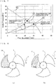
- horizontal axis represents the velocity distribution of the flow in the axis of rotation direction over the positions in the radial direction of the blade of the propeller fan of Embodiment 1.
- the velocity distribution 30 (forward swept shape) represented by a broken line is obtained when the blade 1 does not have the set of regions P, Q, and R, and the velocity distribution 31 (corrected, forward swept shape) represented by the solid line is obtained when the blade 1 has the set of regions P, Q, and R.
- Embodiment 1 since the regions P, Q, and R are set on the blade surface, the effects of increasing or reducing the flow velocity are produced in the velocity distribution to obtain a region Vp in which the flow velocity is increased by the effect of the region P, a region Vq in which the flow velocity is increased by the effect of the region Q, and a region Vr in which the flow velocity is reduced by the effect of the region R.
- the first intersection 25 that is an intersection between the trailing edge 20 and the first concentric circle 9a, which has as its center the axis of rotation 2a of the boss 2 and passes through the leading-edge rearmost point 11, is located between the trailing-edge rearmost point 24 and the trailing-edge foremost point 23.
- the structure according to Embodiment 1 is more specifically defined in terms of the relationship between the first intersection 25 and the shape of the trailing edge 20.
- Fig. 5 is a front view of a propeller fan according to Embodiment 2 as seen from the upstream side in the direction in which the fluid flows.
- each blade 1 has a leading-edge rearmost point 11, a trailing-edge foremost point 23, a trailing-edge rearmost point 24, and a first intersection 25.
- an inflection point 26 is additionally defined.
- a second curved portion 20a and a third curved portion 20b of a trailing edge 20 are connected to each other at the inflection point 26.
- the blade 1 has a shape in which the first intersection 25 and the inflection point 26 are located at the same position on the trailing edge 20. That is, the inflection point 26 is located on a first concentric circle 9a, which has as its center an axis of rotation 2a and passes through the leading-edge rearmost point 11.
- a region P increases the flow quantity on the inner circumferential side of the blade 1 and a region R decreases the flow quantity on the outer circumferential side of the blade 1.
- the velocity distribution is equalized. That is, since the effect produced by the region P and the effect produced by the region R are opposite to each other in terms of changes in flow quantity, when the inflection point 26 is more to the inner circumferential side than the first intersection 25, the flow rate increased by the region P is decreased by the region R.
- the flow rate increased by the leading edge 10 is not decreased by the trailing edge 20 and remains effective. Since regions where the flow rate is low can be efficiently increased and regions where the flow rate is high can be efficiently reduced, the velocity distribution can be equalized. With this arrangement, the drive force for rotating the propeller fan can be reduced to, in turn, reduce the power consumption of the motor.
- Embodiment 3 the relationship between the first intersection 25 and the shape of the trailing edge 20 in Embodiments 1 and 2 are more specifically defined.
- Fig. 6 is a front view of a propeller fan according to Embodiment 3 as seen from the upstream side in the direction in which the fluid flows.
- each blade 1 has a leading-edge rearmost point 11, a trailing-edge foremost point 23, a trailing-edge rearmost point 24, a first intersection 25, and an inflection point 26.
- Fig. 7 is a pressure-quantity (P-Q) chart that represents the air sending performance of the propeller fan.
- the air sending performance of the propeller fan is represented by the relationship between the pressure (static pressure) of a fluid and the flow quantity per unit time (P-Q chart) as illustrated in Fig. 7 . It is known that, when resistance in the passage of air blown by the propeller fan is high, the pressure loss curve rises from a normal pressure loss curve A to a high pressure loss curve B, and an operating point, which is an intersection between the pressure loss curve and a capacity-characteristic curve C of the propeller fan, also shifts.
- the pressure loss represented by the high pressure loss curve B is twice the pressure loss represented by the normal pressure loss curve A in a flow passage.
- An intersection between the normal pressure loss curve A and the capacity-characteristic curve C is a normal operating point, and an intersection between the high pressure loss curve B and the capacity-characteristic curve C is a high pressure loss operating point.
- Fig. 8 illustrates the results of a numerical fluid dynamics analysis performed on streamline limits 14 of a blade surface corresponding to a pressure surface 1a of the blade 1 when the pressure loss is high in the flow passage and when the pressure loss is low in the flow passage. Note that the streamline limits 14 are drawn by connecting vectors of the flow velocities of streams flowing near the surface with lines.
- View (a) of Fig. 8 is a schematic view illustrating the streamline limits 14 on the pressure surface 1a at the normal operating point.
- View (b) of Fig. 8 is a schematic view of the streamline limits 14 at the high pressure loss operating point.
- Dotted lines in view (b) of Fig. 8 represent the streamline limits 14 at the normal operating point.
- the path of the streamline limit 14 on each blade 1 of the propeller fan is as follows: that is, as illustrated in view (b) of Fig. 8 , the fluid having flowed in through the leading-edge rearmost point 11 shifts more to the outer circumferential side than the leading-edge rearmost point 11 on the concentric circle and deviates from a trailing edge 20.
- the blade 1 according to Embodiment 3 has, as illustrated in Fig. 6 , the following structure. That is, letting r be the radius of the propeller fan, which is represented as the length from an axis of rotation 2a to an outer circumferential edge 12 of the blade 1, an intersection between the trailing edge 20 and a first concentric circle 9a, which has as its center the axis of rotation 2a and passes through the leading-edge rearmost point 11, is defined as the first intersection 25, and an intersection between the trailing edge 20 and a second concentric circle 9b, with a radius larger than that of the first concentric circle 9a by 0.1r, is defined as a second intersection 27, the inflection point 26, which connects the second curved portion 20a and the third curved portion 20b to each other, is located between the first intersection 25 and the second intersection 27.
- the inflection point 26 is positioned more to the outer circumferential side of the blade 1 than the first intersection 25.
- the flow quantity increased by the region P is not decreased by the region R.
- the blade 1 has a shape in which the inflection point 26 is located between the first intersection 25 and the second intersection 27, when the propeller fan is used as a high static-pressure propeller fan with which the streamline limits 14 shift to the outer circumferential side of the blade 1, the flow velocity distribution of the fluid can be flattened.
- the pressure loss of the fluid blown from the propeller fan is reduced to, in turn, reduce the drive force for rotating the propeller fan. This reduces the power consumption of the motor.
- the blades 1 of the propeller fan have the forward swept shape.
- the blades 1 of the propeller fan have a backward swept shape.
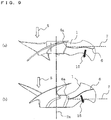
- FIG. 9 View (a) of Fig. 9 is a side view of the propeller fan according to Embodiment 4. In view (a) of Fig. 9 , the position of a chord center line 6 is illustrated.
- chord center line 6 is located downstream of a perpendicular plane 7 in the flow of the fluid.
- the perpendicular plane 7 extends in a direction perpendicular to an axis of rotation 2a of a boss 2 from a contact point 6a where the chord center line 6 abuts against the circumferential wall of the boss 2.
- the blade 1 has a shape in which the chord center line 6 is located downstream of the perpendicular plane 7 in the flow of the fluid (to be referred to as a "backward swept shape” hereinafter).
- chord center line 6 is located upstream of the perpendicular plane 7 in the flow of the fluid.
- An arrow illustrated in view (a) of Fig. 9 indicates a fluid pushing direction 15 in which the fluid is pushed when the blade 1 rotates.
- the fluid flows in a path inclined toward the inner circumferential side (closed flow) of the blade 1.
- the velocity distribution of the forward swept propeller fan is, as illustrated in Fig. 4 , almost flat and improved by the effects of increasing or decreasing the velocity produced by the regions P, Q, and R of the blade 1. Despite this, a high-velocity region remains on the outer circumferential side of the blade 1.
- FIG. 10 View (a) of Fig. 10 is a comparative view between a velocity distribution (forward swept shape) 30 of the forward swept propeller fan and a velocity distribution (backward swept shape) 32 of the backward swept propeller fan.
- the blown air is pushed by the blade 1 in different directions, as mentioned earlier.
- the peak position of the backward swept shape tends to shift more to the inner circumferential side of the blade 1 than the forward swept shape.
- FIGS (b) and (c) of Fig. 10 illustrate the velocity distribution (corrected, backward swept shape) 33 observed when the regions P, Q, and R of the blade 1 according to Embodiment 1 is provided in the backward swept propeller fan according to Embodiment 4. Since the regions P, Q, and R are set on the blade surface, the effects of increasing or reducing the flow velocity are produced in the velocity distribution similarly to Embodiment 1 to obtain a region Vp in which the flow velocity is increased by the effect of the region P, a region Vq in which the flow velocity is increased by the effect of the region Q, and a region Vr in which the flow velocity is reduced by the effect of the region R. Thus, the velocity distribution (corrected, backward swept shape) 33 is obtained.
- FIG. 10 View (d) of Fig. 10 is a comparative view between the velocity distribution (corrected, forward swept shape) 31 of the forward swept propeller fan according to Embodiment 1 and the velocity distribution (backward swept shape) 33 of the backward swept propeller fan according to Embodiment 4.
- chord center line 6 of the backward swept shape is entirely located downstream of the perpendicular plane 7 in the flow of the fluid in the blade shape of the above-described example, the blade 1 still has the functions and produces the effects as described above as long as the blade 1 has a shape in which 70% of the chord center line 6 in length is located downstream of the perpendicular plane 7 in the flow of the fluid.
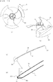
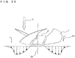
- FIG. 11 View (a) of Fig. 11 is a side view of the propeller fan according to Embodiment 4 and the motor supports 70, to which the propeller fan is attached.
- the above-described backward swept blades 1 each have a shape in which the chord center line 6 is located downstream of the perpendicular plane 7 in the flow of the fluid.
- a length L2 of the leading edge 10 in the axis of rotation direction is limited to fall within 20% of a length L1 of the blade 1 in the axis of rotation direction.
- FIG. 11 View (b) of Fig. 11 is a side view illustrating a forward swept blade 1 for comparison.
- a length L12 of the leading edge 10 in the axis of rotation direction does not fall within 20% of a length L11 of the blade 1 in the axis of rotation direction.
- FIG. 11 View (c) of Fig. 11 illustrates the behavior of a Karman vortex street 71 of the fluid having passed through the motor supports 70.
- FIG. 11 View (d) of Fig. 11 is a sectional top view of an outdoor unit of an air-conditioning apparatus in which an air-sending device that includes the propeller fan according to Embodiment 4 attached to the motor supports is disposed.
- the Karman vortex street 71 collides with a portion of the blades 1 near the leading edges 10, thereby causing a large pressure fluctuation. As a result, so-called aerodynamic noise is generated.
- the aerodynamic noise is known to increase noise.
- the Karman vortex street 71 is attenuated as it moves to the downstream side.
- the length L12 of the leading edge 10 in the axis of rotation direction does not fall within 20% of the maximum length L11 of the blade 1 in the axis of rotation direction. Accordingly, a distance L13 between the outer circumferential side of the leading edge 10 and the motor supports 70 is small. This causes the blade 1 to pass through the strong Karman vortex street 71 generated by the motor supports 70 and to collide with the leading edge 10 of the blade 1. As a result, a large pressure fluctuation occurs on the leading edge 10 so that the aerodynamic noise is increased.
- the length L2 of the leading edge 10 in the axis of rotation direction falls within 20% of the maximum length L1 of the blade 1 in the axis of rotation direction, and accordingly, a distance L3 between the outer circumferential side of the leading edge 10 and the motor supports 70 is increased.
- the Karman vortex street 71 since the Karman vortex street 71 has been attenuated by its movement across a certain distance, the aerodynamic noise can be suppressed even when the blade 1 passes through and cut the Karman vortex street 71.
- An outdoor unit of an air-conditioning apparatus attaining low noise can be provided using such a built-in propeller fan, as illustrated in view (d) of Fig. 11 .
- FIG. 12 View (a) of Fig. 12 is a front view of the propeller fan as seen from the upstream side of the flow of the fluid.
- FIG. 12 View (b) of Fig. 12 is a sectional view of the blade of the propeller fan taken in the radial direction.
- a winglet 40 is formed on the outer circumferential edge 12 of the blade 1.
- the winglet 40 is bent to the upstream side of the flow of the fluid.
- a flow of the fluid from the high static-pressure side, that is, the side of a pressure surface 1a to the low static-pressure side, that is, the side of a suction surface 1b is generated on the outer circumferential edge 12 of the blade 1.
- a wingtip vortex is formed by this flow.
- the wingtip vortex has a spiral vortex structure.
- the wingtip vortex generated in the preceding blade 1 flows into the succeeding blade 1, interferes with the succeeding blade 1, and collides with the wall surface of a bell-mouth disposed around the propeller fan, so that a static pressure fluctuation occurs. This increases noise and motor input.
- the winglet 40 produces the effect of suppressing the wingtip vortex as illustrated in view (b) of Fig. 12 .
- the winglet 40 allows the fluid to smoothly flow from the high static-pressure side, that is, the side of the pressure surface 1a to the low static-pressure side, that is, the side of the suction surface 1b of the blade 1 along its curved portion.
- the winglet 40 should be disposed more to the outer circumferential side than a position that is separated from the axis of rotation 2a by 0.8r. This is done to allow the winglet 40 to produce effects of both suppressing the wingtip vortex and improving the bending strength of the blade 1.
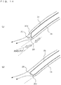
- Fig. 13 illustrates views of the cross-sectional shape of the trailing edge 20 of the blade 1.
- FIG. 13 View (a) of Fig. 13 is a front view illustrating a cross-sectional position 50 of the propeller fan.
- FIG. 13 View (b) of Fig. 13 is a perspective view illustrating the cross-sectional position 50 of the propeller fan.
- View (c) of Fig. 13 is a sectional view of the blade 1 as seen from the cross-sectional position 50 illustrated in views (a) and (b) of Fig. 13 .
- View (d) of Fig. 13 is an enlarged sectional view of the trailing edge 20 of the blade 1 illustrated in view (c) of Fig. 13 .
- the cross-section of the blade 1 illustrated in views (c) and (d) of Fig. 13 has the cross-sectional shape of the blade 1 as seen from the cross-sectional position 50 illustrated in (a) and (b) of Fig. 13 .
- the blade 1 has the pressure surface 1a and the suction surface 1b.
- the cross-section of the trailing edge 20 of the blade 1 has two arcs, that is, a first arc 20c and a second arc 20d, as illustrated in view (d) of Fig. 13 .
- a cross-sectional radius r1 of the first arc 20c continuous with the pressure surface 1a is specified to be larger than a cross-sectional radius r2 of the second arc 20d continuous with the suction surface 1b.
- Fig. 14 shows sectional views of the cross-sectional shape of the trailing edge 20 of the blade 1.
- the cross-sectional radius r1 of the first arc 20c on the side of the pressure surface 1a is set large, and the cross-sectional radius r2 of the second arc 20d on the side of the suction surface 1b is set small (to zero, which represents a right-angled cross-section).
- Streamlines near the blade surface are illustrated in views (a) and (b) of Fig. 14 .
- the fluid pushed on the pressure surface 1a changes its direction to flow, when it moves from the trailing edge 20 of the blade 1.
- the angle of shift at this time is defined as an angle ⁇ in view (a) of Fig. 14 .
- the first arc 20c having the cross-sectional radius r1 is formed on the trailing edge 20 on the side of the pressure surface 1a in the blade 1 according to each of Embodiments 1 to 4.
- the separation region 51 is not generated.
- the separation of the fluid on the trailing edge 20 is suppressed and the energy loss of the fluid is reduced. This reduces the drive force for rotating the propeller fan and the power consumption of the motor.
- the cross-sectional shape of the entire trailing edge 20 has the first arc 20c and the second arc 20d in the above-described example, it may be applied only to the third curved portion 20b on the outer circumferential side, which is a region where the flow velocity is high in the trailing edge 20.
- FIGS (a) and (b) of Fig. 15 are perspective views of a position where the trailing edge 20 of the blade 1 and the boss 2 are connected to each other.
- the connecting portion 60 where the trailing edge 20 of the blade 1 and the boss 2 are connected to each other, has an edge shape that is not rounded and has a valley fold line.
- Fig. 16 illustrates forces applied to the connecting portion 60, where the trailing edge 20 of the blade 1 and the boss 2 are connected to each other, when the blade 1 rotates.
- a centrifugal force 65a and a tensile force 65b act on the center of gravity 61 of the blade 1.
- a resultant force 65c of these forces acts on the center of gravity 61 of the blade 1.
- Hatching in Fig. 16 indicates the third curved portion 20b that reduces the blade area in the trailing edge 20 of the blade 1.
- the vector of the resultant force 65c is directed to the upstream side in the fluid flow direction 5 in which the fluid flows.
- the tensile force acts on the connecting portion 60 where the trailing edge 20 of the blade 1 and the boss 2 are connected to each other.
- F the centrifugal force
- m the mass
- a the acceleration
- v the velocity
- ⁇ the angular acceleration
- the amount of resin for a rounding process can be reduced to obtain a lightweight fan, and the power consumption of the motor, in turn, can be reduced.
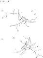
- Fig. 17 is a schematic view illustrating how propeller fans are packed.
- a stack of propeller fans is contained in a cardboard box 81 for packing.
- a leading edge 10 of a blade 1 keeps a distance L from the bottom surface of the cardboard box 81.
- the stack of propeller fans is packed so as to put lid surfaces 2b of the bosses 2 face up.
- Fig. 18 shows schematic views for explaining the shape of a propeller fan without a boss using the blades according to the present invention.
- Fig. 19 is a front view for explaining the shape of the propeller fan without a boss using the blades according to the present invention.
- the example of the propeller fan includes a boss, and the blades 1 are attached to the circumferential surface of the boss 2 in Embodiments, the structure of the blade 1 according to Embodiments can be applied to a propeller fan without a boss as illustrated in Figs. 18 and 19 .
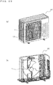
- FIGS (a) and (b) of Fig. 20 are perspective views illustrating an outdoor unit of an air-conditioning apparatus using the propeller fan according to the present invention.
- the propeller fan according to each of Embodiments 1 to 4 used for an outdoor unit 90 is disposed in the outdoor unit 90 together with a bell-mouth 13 and sends outdoor air to an outdoor heat exchanger for exchanging heat. In doing so, since the velocity distribution of blown air in the axis of rotation direction is equalized over the positions in the radial direction of the blade of the propeller fan, the outdoor unit 90 featuring a reduced pressure loss and reduced power consumption can be realized.
- the blade shape of the propeller fan described in Embodiments can be used in various air-sending devices.
- the blade shape of the propeller fan can be used in an indoor unit of the air-conditioning apparatus.
- the blade shape of the propeller fan according to Embodiments can be widely applied to the blade shapes of, for example, general air-sending devices, ventilating fans, pumps, and axial flow compressors that deliver a fluid.
Landscapes
- Engineering & Computer Science (AREA)
- Mechanical Engineering (AREA)
- General Engineering & Computer Science (AREA)
- Chemical & Material Sciences (AREA)
- Combustion & Propulsion (AREA)
- Structures Of Non-Positive Displacement Pumps (AREA)
- Air-Conditioning Room Units, And Self-Contained Units In General (AREA)
Applications Claiming Priority (1)
| Application Number | Priority Date | Filing Date | Title |
|---|---|---|---|
| JP2013165454A JP5980180B2 (ja) | 2013-08-08 | 2013-08-08 | 軸流ファン、及び、その軸流ファンを有する空気調和機 |
Publications (3)
| Publication Number | Publication Date |
|---|---|
| EP2835538A2 EP2835538A2 (en) | 2015-02-11 |
| EP2835538A3 EP2835538A3 (en) | 2015-08-05 |
| EP2835538B1 true EP2835538B1 (en) | 2017-09-27 |
Family
ID=51257411
Family Applications (1)
| Application Number | Title | Priority Date | Filing Date |
|---|---|---|---|
| EP14179447.9A Active EP2835538B1 (en) | 2013-08-08 | 2014-08-01 | Axial flow fan and air-conditioning apparatus having the same |
Country Status (4)
| Country | Link |
|---|---|
| US (1) | US9605686B2 (enExample) |
| EP (1) | EP2835538B1 (enExample) |
| JP (1) | JP5980180B2 (enExample) |
| CN (2) | CN104343730B (enExample) |
Cited By (2)
| Publication number | Priority date | Publication date | Assignee | Title |
|---|---|---|---|---|
| US12456931B2 (en) | 2021-02-19 | 2025-10-28 | Samsung Electronics Co., Ltd. | Power supply, electronic device, and method for controlling same |
| US12620892B2 (en) | 2021-02-18 | 2026-05-05 | Samsung Electronics Co., Ltd. | Power supply, electronic device, and method for controlling same |
Families Citing this family (42)
| Publication number | Priority date | Publication date | Assignee | Title |
|---|---|---|---|---|
| JP5980180B2 (ja) | 2013-08-08 | 2016-08-31 | 三菱電機株式会社 | 軸流ファン、及び、その軸流ファンを有する空気調和機 |
| SG10201912863UA (en) * | 2014-08-07 | 2020-02-27 | Mitsubishi Electric Corp | Axial flow fan and air-conditioning apparatus having axial flow fan |
| JP6409666B2 (ja) * | 2014-09-18 | 2018-10-24 | 株式会社デンソー | 送風機 |
| US10378781B2 (en) * | 2015-06-19 | 2019-08-13 | Mitsubishi Electric Corporation | Outdoor unit for refrigeration cycle apparatus, and refrigeration cycle apparatus |
| DE102015216579A1 (de) * | 2015-08-31 | 2017-03-02 | Ziehl-Abegg Se | Lüfterrad, Lüfter und System mit mindestens einem Lüfter |
| JP2017053295A (ja) * | 2015-09-11 | 2017-03-16 | 三星電子株式会社Samsung Electronics Co.,Ltd. | 送風機および室外機 |
| WO2017077564A1 (ja) * | 2015-11-02 | 2017-05-11 | 三菱電機株式会社 | 軸流ファン、及び、その軸流ファンを有する空気調和装置 |
| KR102479815B1 (ko) * | 2015-11-30 | 2022-12-23 | 삼성전자주식회사 | 송풍팬 및 이를 구비하는 공기 조화기 |
| JP6482679B2 (ja) * | 2015-11-30 | 2019-03-13 | 三菱電機株式会社 | 室外ユニット |
| USD858737S1 (en) * | 2017-03-16 | 2019-09-03 | Mitsubishi Electric Corporation | Propeller fan |
| US11391295B2 (en) | 2017-05-22 | 2022-07-19 | Fujitsu General Limited | Propeller fan |
| JP6957971B2 (ja) * | 2017-05-22 | 2021-11-02 | 株式会社富士通ゼネラル | プロペラファン |
| CN107023513A (zh) * | 2017-06-16 | 2017-08-08 | 广东美的制冷设备有限公司 | 轴流风轮及空调器 |
| DE102017212231A1 (de) * | 2017-07-18 | 2019-01-24 | Ziehl-Abegg Se | Flügel für das Laufrad eines Ventilators, Laufrad sowie Axialventilator, Diagonalventilator oder Radialventilator |
| JP1600722S (enExample) * | 2017-08-09 | 2018-04-02 | ||
| USD870254S1 (en) * | 2017-08-09 | 2019-12-17 | Mitsubishi Electric Corporation | Propeller fan |
| JP1600724S (enExample) * | 2017-08-09 | 2018-04-02 | ||
| CN110914553B (zh) * | 2017-08-14 | 2021-02-19 | 三菱电机株式会社 | 叶轮、送风机及空调装置 |
| CN107288927A (zh) * | 2017-08-17 | 2017-10-24 | 苏州欧比特机械有限公司 | 一种风扇叶轮 |
| USD911512S1 (en) | 2018-01-31 | 2021-02-23 | Carrier Corporation | Axial flow fan |
| JP2019138175A (ja) * | 2018-02-07 | 2019-08-22 | 株式会社デンソー | 送風装置 |
| JP6931776B2 (ja) * | 2018-03-28 | 2021-09-08 | パナソニックIpマネジメント株式会社 | 軸流ファン |
| US11519422B2 (en) * | 2018-05-09 | 2022-12-06 | York Guangzhou Air Conditioning And Refrigeration Co., Ltd. | Blade and axial flow impeller using same |
| JP7150480B2 (ja) * | 2018-05-30 | 2022-10-11 | 三菱重工サーマルシステムズ株式会社 | プロペラファン及びこれを備えた空気調和機用室外ユニット |
| JP6998462B2 (ja) * | 2018-06-22 | 2022-01-18 | 三菱重工エンジン&ターボチャージャ株式会社 | 回転翼及びこの回転翼を備える遠心圧縮機 |
| WO2020103400A1 (zh) * | 2018-11-22 | 2020-05-28 | 广东美的制冷设备有限公司 | 轴流风轮及具有其的空调器 |
| WO2020110167A1 (ja) * | 2018-11-26 | 2020-06-04 | 三菱電機株式会社 | 翼車および軸流送風機 |
| CN109441879A (zh) * | 2018-12-26 | 2019-03-08 | 浙江科贸实业有限公司 | 一种复合式叶轮通风机及其复合式叶轮 |
| USD980965S1 (en) * | 2019-05-07 | 2023-03-14 | Carrier Corporation | Leading edge of a fan blade |
| WO2020250364A1 (ja) * | 2019-06-13 | 2020-12-17 | 三菱電機株式会社 | 軸流ファン、送風装置、及び、冷凍サイクル装置 |
| US11128184B2 (en) * | 2019-06-19 | 2021-09-21 | Michael Cummings | Magnetic rotating member and methods relating to same |
| US11598217B2 (en) | 2019-10-17 | 2023-03-07 | Dassault Systemes Simulia Corp. | Method for automatic calculation of axial cooling fan shroud circular opening size |
| US11835054B2 (en) * | 2019-10-17 | 2023-12-05 | Dassault Systemes Simulia Corp. | Method for automatic detection of axial cooling fan rotation direction |
| CN111350694B (zh) * | 2020-03-13 | 2021-02-19 | 浙江上风高科专风实业有限公司 | 一种叶尖弯曲的减耗风机叶片的加工方法 |
| KR102891986B1 (ko) * | 2020-07-24 | 2025-12-01 | 삼성전자주식회사 | 공기조화기의 실외기 |
| WO2022113631A1 (ja) * | 2020-11-27 | 2022-06-02 | 株式会社デンソー | ファン装置 |
| JP2023101366A (ja) * | 2022-01-07 | 2023-07-20 | 京セラインダストリアルツールズ株式会社 | 衣服用ファン装置及びファン付き衣服 |
| CN115419617A (zh) * | 2022-09-16 | 2022-12-02 | 宁波有铭电器有限公司 | 一种送风装置总成 |
| USD1048368S1 (en) * | 2023-03-09 | 2024-10-22 | Regal Beloit Italy S.P.A. | Fan wheel |
| USD1115011S1 (en) * | 2023-04-04 | 2026-02-24 | Mitsubishi Electric Corporation | Propeller fan |
| JP1788155S (ja) * | 2024-03-08 | 2025-01-06 | プロペラファン | |
| DE102024204781A1 (de) * | 2024-05-23 | 2025-11-27 | Brose Fahrzeugteile SE & Co. Kommanditgesellschaft, Würzburg | Lüfterrad für ein Kraftfahrzeug |
Family Cites Families (20)
| Publication number | Priority date | Publication date | Assignee | Title |
|---|---|---|---|---|
| US77888A (en) * | 1868-05-12 | kennedy | ||
| US1895252A (en) * | 1931-01-23 | 1933-01-24 | Emmanuel G Kontos | Propeller |
| FR2588925A1 (fr) * | 1985-10-23 | 1987-04-24 | Etri Sa | Ventilateur equipe de moyens pour reduire le bruit engendre par la rotation de ses pales |
| US5906179A (en) * | 1997-06-27 | 1999-05-25 | Siemens Canada Limited | High efficiency, low solidity, low weight, axial flow fan |
| JPH1144432A (ja) * | 1997-07-24 | 1999-02-16 | Hitachi Ltd | 空気調和機 |
| JP3039521B2 (ja) * | 1998-07-02 | 2000-05-08 | ダイキン工業株式会社 | 送風機用羽根車 |
| KR100393993B1 (ko) * | 2000-10-02 | 2003-08-09 | 엘지전자 주식회사 | 축류팬 |
| JP4132826B2 (ja) * | 2002-01-10 | 2008-08-13 | シャープ株式会社 | プロペラファンおよびその成型金型並びに流体送り装置 |
| JP4467952B2 (ja) * | 2003-11-10 | 2010-05-26 | 東芝キヤリア株式会社 | プロペラファン、これを用いた空気調和機用室外ユニット |
| JP4649146B2 (ja) * | 2004-08-26 | 2011-03-09 | ダイキン工業株式会社 | プロペラファン |
| JP4689262B2 (ja) * | 2004-12-21 | 2011-05-25 | 東芝キヤリア株式会社 | 軸流ファン、空気調和機の室外機 |
| SI22636A (sl) * | 2007-10-24 | 2009-04-30 | Hidria Rotomatika D.O.O. | Lopatica aksialnega ventilatorja z valovito tlaäśno in sesalno povrĺ ino |
| JP4388992B1 (ja) * | 2008-10-22 | 2009-12-24 | シャープ株式会社 | プロペラファン、流体送り装置および成型金型 |
| JP5366532B2 (ja) * | 2008-12-24 | 2013-12-11 | 東芝キヤリア株式会社 | 軸流ファンおよび空気調和機の室外機 |
| JP5127854B2 (ja) * | 2010-03-11 | 2013-01-23 | 三菱電機株式会社 | 送風機及びヒートポンプ装置 |
| CN102893034B (zh) * | 2010-05-13 | 2015-11-25 | 三菱电机株式会社 | 轴流风机 |
| JP2012012942A (ja) | 2010-06-29 | 2012-01-19 | Mitsubishi Electric Corp | プロペラファン |
| JP2013130125A (ja) | 2011-12-21 | 2013-07-04 | Toshiba Carrier Corp | プロペラファンおよびこれを用いた熱源ユニット |
| CN202659571U (zh) * | 2012-06-28 | 2013-01-09 | 珠海格力电器股份有限公司 | 轴流风叶及包括该轴流风叶的空调 |
| JP5980180B2 (ja) | 2013-08-08 | 2016-08-31 | 三菱電機株式会社 | 軸流ファン、及び、その軸流ファンを有する空気調和機 |
-
2013
- 2013-08-08 JP JP2013165454A patent/JP5980180B2/ja active Active
-
2014
- 2014-07-31 US US14/447,977 patent/US9605686B2/en active Active
- 2014-08-01 EP EP14179447.9A patent/EP2835538B1/en active Active
- 2014-08-08 CN CN201410389328.7A patent/CN104343730B/zh active Active
- 2014-08-08 CN CN201420447330.0U patent/CN204239327U/zh not_active Expired - Lifetime
Non-Patent Citations (1)
| Title |
|---|
| None * |
Cited By (2)
| Publication number | Priority date | Publication date | Assignee | Title |
|---|---|---|---|---|
| US12620892B2 (en) | 2021-02-18 | 2026-05-05 | Samsung Electronics Co., Ltd. | Power supply, electronic device, and method for controlling same |
| US12456931B2 (en) | 2021-02-19 | 2025-10-28 | Samsung Electronics Co., Ltd. | Power supply, electronic device, and method for controlling same |
Also Published As
| Publication number | Publication date |
|---|---|
| CN104343730A (zh) | 2015-02-11 |
| US9605686B2 (en) | 2017-03-28 |
| EP2835538A2 (en) | 2015-02-11 |
| CN104343730B (zh) | 2017-04-12 |
| US20150044058A1 (en) | 2015-02-12 |
| JP2015034503A (ja) | 2015-02-19 |
| EP2835538A3 (en) | 2015-08-05 |
| CN204239327U (zh) | 2015-04-01 |
| JP5980180B2 (ja) | 2016-08-31 |
Similar Documents
| Publication | Publication Date | Title |
|---|---|---|
| EP2835538B1 (en) | Axial flow fan and air-conditioning apparatus having the same | |
| US11506211B2 (en) | Counter-rotating fan | |
| EP2997263B1 (en) | Axial fan | |
| US8475131B2 (en) | Centrifugal compressor | |
| CN103597288B (zh) | 空气调节机 | |
| JP5263198B2 (ja) | 羽根車と送風機及びそれを用いた空気調和機 | |
| EP2657530B1 (en) | Through-flow fan, and indoor unit for air conditioner | |
| US9765787B2 (en) | Centrifugal blower housing having surface structures, system, and method of assembly | |
| EP2426362A2 (en) | Turbo fan and air conditioner with turbo fan | |
| EP3372841B1 (en) | Axial fan and air-conditioning device having said axial fan | |
| EP2530331A2 (en) | Axial fan assembly for a vehicle cooling system | |
| EP3667096B1 (en) | Propeller fan, air blowing device, and refrigerating cycle device | |
| EP3992468B1 (en) | Axial flow fan, blowing device, and refrigeration cycle device | |
| KR102562563B1 (ko) | 터보팬 및 이를 갖는 에어컨 | |
| JP2011179331A (ja) | 送風機とその送風機を用いた空気調和機 | |
| EP2905474B1 (en) | Propeller fan | |
| CN216430052U (zh) | 一种轴流叶轮、轴流风机及空调器 | |
| CN212130847U (zh) | 一种轴流风叶、风机组件及其空调器 | |
| JPWO2017081761A1 (ja) | 軸流ファン、及び、その軸流ファンを有する空気調和装置 | |
| KR20120023319A (ko) | 공기조화기용 터보팬 | |
| KR950006563B1 (ko) | 시로코 팬(Sirocco Fan) 빔 처짐형 블레이드(Blade)형상 결정방법 | |
| CN116026023B (zh) | 一种空调室外机及空调器 | |
| KR101826348B1 (ko) | 횡류팬 및 이를 구비한 공기 조화기 |
Legal Events
| Date | Code | Title | Description |
|---|---|---|---|
| PUAI | Public reference made under article 153(3) epc to a published international application that has entered the european phase |
Free format text: ORIGINAL CODE: 0009012 |
|
| 17P | Request for examination filed |
Effective date: 20140801 |
|
| AK | Designated contracting states |
Kind code of ref document: A2 Designated state(s): AL AT BE BG CH CY CZ DE DK EE ES FI FR GB GR HR HU IE IS IT LI LT LU LV MC MK MT NL NO PL PT RO RS SE SI SK SM TR |
|
| AX | Request for extension of the european patent |
Extension state: BA ME |
|
| PUAL | Search report despatched |
Free format text: ORIGINAL CODE: 0009013 |
|
| AK | Designated contracting states |
Kind code of ref document: A3 Designated state(s): AL AT BE BG CH CY CZ DE DK EE ES FI FR GB GR HR HU IE IS IT LI LT LU LV MC MK MT NL NO PL PT RO RS SE SI SK SM TR |
|
| AX | Request for extension of the european patent |
Extension state: BA ME |
|
| RIC1 | Information provided on ipc code assigned before grant |
Ipc: F24F 1/08 20110101ALI20150626BHEP Ipc: F04D 25/08 20060101AFI20150626BHEP Ipc: F04D 29/66 20060101ALI20150626BHEP Ipc: F04D 29/38 20060101ALI20150626BHEP Ipc: F24F 1/06 20110101ALI20150626BHEP |
|
| R17P | Request for examination filed (corrected) |
Effective date: 20151202 |
|
| RBV | Designated contracting states (corrected) |
Designated state(s): AL AT BE BG CH CY CZ DE DK EE ES FI FR GB GR HR HU IE IS IT LI LT LU LV MC MK MT NL NO PL PT RO RS SE SI SK SM TR |
|
| 17Q | First examination report despatched |
Effective date: 20160713 |
|
| GRAP | Despatch of communication of intention to grant a patent |
Free format text: ORIGINAL CODE: EPIDOSNIGR1 |
|
| INTG | Intention to grant announced |
Effective date: 20170222 |
|
| GRAS | Grant fee paid |
Free format text: ORIGINAL CODE: EPIDOSNIGR3 |
|
| GRAA | (expected) grant |
Free format text: ORIGINAL CODE: 0009210 |
|
| AK | Designated contracting states |
Kind code of ref document: B1 Designated state(s): AL AT BE BG CH CY CZ DE DK EE ES FI FR GB GR HR HU IE IS IT LI LT LU LV MC MK MT NL NO PL PT RO RS SE SI SK SM TR |
|
| REG | Reference to a national code |
Ref country code: GB Ref legal event code: FG4D |
|
| REG | Reference to a national code |
Ref country code: CH Ref legal event code: EP |
|
| REG | Reference to a national code |
Ref country code: AT Ref legal event code: REF Ref document number: 932238 Country of ref document: AT Kind code of ref document: T Effective date: 20171015 |
|
| REG | Reference to a national code |
Ref country code: IE Ref legal event code: FG4D |
|
| REG | Reference to a national code |
Ref country code: DE Ref legal event code: R096 Ref document number: 602014014999 Country of ref document: DE |
|
| PG25 | Lapsed in a contracting state [announced via postgrant information from national office to epo] |
Ref country code: SE Free format text: LAPSE BECAUSE OF FAILURE TO SUBMIT A TRANSLATION OF THE DESCRIPTION OR TO PAY THE FEE WITHIN THE PRESCRIBED TIME-LIMIT Effective date: 20170927 Ref country code: HR Free format text: LAPSE BECAUSE OF FAILURE TO SUBMIT A TRANSLATION OF THE DESCRIPTION OR TO PAY THE FEE WITHIN THE PRESCRIBED TIME-LIMIT Effective date: 20170927 Ref country code: FI Free format text: LAPSE BECAUSE OF FAILURE TO SUBMIT A TRANSLATION OF THE DESCRIPTION OR TO PAY THE FEE WITHIN THE PRESCRIBED TIME-LIMIT Effective date: 20170927 Ref country code: NO Free format text: LAPSE BECAUSE OF FAILURE TO SUBMIT A TRANSLATION OF THE DESCRIPTION OR TO PAY THE FEE WITHIN THE PRESCRIBED TIME-LIMIT Effective date: 20171227 Ref country code: LT Free format text: LAPSE BECAUSE OF FAILURE TO SUBMIT A TRANSLATION OF THE DESCRIPTION OR TO PAY THE FEE WITHIN THE PRESCRIBED TIME-LIMIT Effective date: 20170927 |
|
| REG | Reference to a national code |
Ref country code: NL Ref legal event code: MP Effective date: 20170927 |
|
| REG | Reference to a national code |
Ref country code: LT Ref legal event code: MG4D |
|
| REG | Reference to a national code |
Ref country code: AT Ref legal event code: MK05 Ref document number: 932238 Country of ref document: AT Kind code of ref document: T Effective date: 20170927 |
|
| PG25 | Lapsed in a contracting state [announced via postgrant information from national office to epo] |
Ref country code: RS Free format text: LAPSE BECAUSE OF FAILURE TO SUBMIT A TRANSLATION OF THE DESCRIPTION OR TO PAY THE FEE WITHIN THE PRESCRIBED TIME-LIMIT Effective date: 20170927 Ref country code: LV Free format text: LAPSE BECAUSE OF FAILURE TO SUBMIT A TRANSLATION OF THE DESCRIPTION OR TO PAY THE FEE WITHIN THE PRESCRIBED TIME-LIMIT Effective date: 20170927 Ref country code: GR Free format text: LAPSE BECAUSE OF FAILURE TO SUBMIT A TRANSLATION OF THE DESCRIPTION OR TO PAY THE FEE WITHIN THE PRESCRIBED TIME-LIMIT Effective date: 20171228 Ref country code: BG Free format text: LAPSE BECAUSE OF FAILURE TO SUBMIT A TRANSLATION OF THE DESCRIPTION OR TO PAY THE FEE WITHIN THE PRESCRIBED TIME-LIMIT Effective date: 20171227 |
|
| PG25 | Lapsed in a contracting state [announced via postgrant information from national office to epo] |
Ref country code: NL Free format text: LAPSE BECAUSE OF FAILURE TO SUBMIT A TRANSLATION OF THE DESCRIPTION OR TO PAY THE FEE WITHIN THE PRESCRIBED TIME-LIMIT Effective date: 20170927 |
|
| PG25 | Lapsed in a contracting state [announced via postgrant information from national office to epo] |
Ref country code: CZ Free format text: LAPSE BECAUSE OF FAILURE TO SUBMIT A TRANSLATION OF THE DESCRIPTION OR TO PAY THE FEE WITHIN THE PRESCRIBED TIME-LIMIT Effective date: 20170927 Ref country code: ES Free format text: LAPSE BECAUSE OF FAILURE TO SUBMIT A TRANSLATION OF THE DESCRIPTION OR TO PAY THE FEE WITHIN THE PRESCRIBED TIME-LIMIT Effective date: 20170927 Ref country code: RO Free format text: LAPSE BECAUSE OF FAILURE TO SUBMIT A TRANSLATION OF THE DESCRIPTION OR TO PAY THE FEE WITHIN THE PRESCRIBED TIME-LIMIT Effective date: 20170927 |
|
| PG25 | Lapsed in a contracting state [announced via postgrant information from national office to epo] |
Ref country code: SM Free format text: LAPSE BECAUSE OF FAILURE TO SUBMIT A TRANSLATION OF THE DESCRIPTION OR TO PAY THE FEE WITHIN THE PRESCRIBED TIME-LIMIT Effective date: 20170927 Ref country code: SK Free format text: LAPSE BECAUSE OF FAILURE TO SUBMIT A TRANSLATION OF THE DESCRIPTION OR TO PAY THE FEE WITHIN THE PRESCRIBED TIME-LIMIT Effective date: 20170927 Ref country code: EE Free format text: LAPSE BECAUSE OF FAILURE TO SUBMIT A TRANSLATION OF THE DESCRIPTION OR TO PAY THE FEE WITHIN THE PRESCRIBED TIME-LIMIT Effective date: 20170927 Ref country code: AT Free format text: LAPSE BECAUSE OF FAILURE TO SUBMIT A TRANSLATION OF THE DESCRIPTION OR TO PAY THE FEE WITHIN THE PRESCRIBED TIME-LIMIT Effective date: 20170927 Ref country code: IS Free format text: LAPSE BECAUSE OF FAILURE TO SUBMIT A TRANSLATION OF THE DESCRIPTION OR TO PAY THE FEE WITHIN THE PRESCRIBED TIME-LIMIT Effective date: 20180127 |
|
| REG | Reference to a national code |
Ref country code: DE Ref legal event code: R097 Ref document number: 602014014999 Country of ref document: DE |
|
| PG25 | Lapsed in a contracting state [announced via postgrant information from national office to epo] |
Ref country code: DK Free format text: LAPSE BECAUSE OF FAILURE TO SUBMIT A TRANSLATION OF THE DESCRIPTION OR TO PAY THE FEE WITHIN THE PRESCRIBED TIME-LIMIT Effective date: 20170927 |
|
| PLBE | No opposition filed within time limit |
Free format text: ORIGINAL CODE: 0009261 |
|
| STAA | Information on the status of an ep patent application or granted ep patent |
Free format text: STATUS: NO OPPOSITION FILED WITHIN TIME LIMIT |
|
| PG25 | Lapsed in a contracting state [announced via postgrant information from national office to epo] |
Ref country code: PL Free format text: LAPSE BECAUSE OF FAILURE TO SUBMIT A TRANSLATION OF THE DESCRIPTION OR TO PAY THE FEE WITHIN THE PRESCRIBED TIME-LIMIT Effective date: 20170927 |
|
| 26N | No opposition filed |
Effective date: 20180628 |
|
| PG25 | Lapsed in a contracting state [announced via postgrant information from national office to epo] |
Ref country code: SI Free format text: LAPSE BECAUSE OF FAILURE TO SUBMIT A TRANSLATION OF THE DESCRIPTION OR TO PAY THE FEE WITHIN THE PRESCRIBED TIME-LIMIT Effective date: 20170927 |
|
| PG25 | Lapsed in a contracting state [announced via postgrant information from national office to epo] |
Ref country code: MC Free format text: LAPSE BECAUSE OF FAILURE TO SUBMIT A TRANSLATION OF THE DESCRIPTION OR TO PAY THE FEE WITHIN THE PRESCRIBED TIME-LIMIT Effective date: 20170927 |
|
| REG | Reference to a national code |
Ref country code: CH Ref legal event code: PL |
|
| PG25 | Lapsed in a contracting state [announced via postgrant information from national office to epo] |
Ref country code: LI Free format text: LAPSE BECAUSE OF NON-PAYMENT OF DUE FEES Effective date: 20180831 Ref country code: LU Free format text: LAPSE BECAUSE OF NON-PAYMENT OF DUE FEES Effective date: 20180801 Ref country code: CH Free format text: LAPSE BECAUSE OF NON-PAYMENT OF DUE FEES Effective date: 20180831 |
|
| REG | Reference to a national code |
Ref country code: BE Ref legal event code: MM Effective date: 20180831 |
|
| REG | Reference to a national code |
Ref country code: IE Ref legal event code: MM4A |
|
| PG25 | Lapsed in a contracting state [announced via postgrant information from national office to epo] |
Ref country code: IE Free format text: LAPSE BECAUSE OF NON-PAYMENT OF DUE FEES Effective date: 20180801 |
|
| PG25 | Lapsed in a contracting state [announced via postgrant information from national office to epo] |
Ref country code: FR Free format text: LAPSE BECAUSE OF NON-PAYMENT OF DUE FEES Effective date: 20180831 Ref country code: BE Free format text: LAPSE BECAUSE OF NON-PAYMENT OF DUE FEES Effective date: 20180831 |
|
| PG25 | Lapsed in a contracting state [announced via postgrant information from national office to epo] |
Ref country code: MT Free format text: LAPSE BECAUSE OF NON-PAYMENT OF DUE FEES Effective date: 20180801 |
|
| PG25 | Lapsed in a contracting state [announced via postgrant information from national office to epo] |
Ref country code: TR Free format text: LAPSE BECAUSE OF FAILURE TO SUBMIT A TRANSLATION OF THE DESCRIPTION OR TO PAY THE FEE WITHIN THE PRESCRIBED TIME-LIMIT Effective date: 20170927 |
|
| PG25 | Lapsed in a contracting state [announced via postgrant information from national office to epo] |
Ref country code: HU Free format text: LAPSE BECAUSE OF FAILURE TO SUBMIT A TRANSLATION OF THE DESCRIPTION OR TO PAY THE FEE WITHIN THE PRESCRIBED TIME-LIMIT; INVALID AB INITIO Effective date: 20140801 Ref country code: PT Free format text: LAPSE BECAUSE OF FAILURE TO SUBMIT A TRANSLATION OF THE DESCRIPTION OR TO PAY THE FEE WITHIN THE PRESCRIBED TIME-LIMIT Effective date: 20170927 |
|
| PG25 | Lapsed in a contracting state [announced via postgrant information from national office to epo] |
Ref country code: CY Free format text: LAPSE BECAUSE OF FAILURE TO SUBMIT A TRANSLATION OF THE DESCRIPTION OR TO PAY THE FEE WITHIN THE PRESCRIBED TIME-LIMIT Effective date: 20170927 Ref country code: MK Free format text: LAPSE BECAUSE OF NON-PAYMENT OF DUE FEES Effective date: 20170927 |
|
| PG25 | Lapsed in a contracting state [announced via postgrant information from national office to epo] |
Ref country code: AL Free format text: LAPSE BECAUSE OF FAILURE TO SUBMIT A TRANSLATION OF THE DESCRIPTION OR TO PAY THE FEE WITHIN THE PRESCRIBED TIME-LIMIT Effective date: 20170927 |
|
| REG | Reference to a national code |
Ref country code: DE Ref legal event code: R084 Ref document number: 602014014999 Country of ref document: DE |
|
| REG | Reference to a national code |
Ref country code: GB Ref legal event code: 746 Effective date: 20200817 |
|
| P01 | Opt-out of the competence of the unified patent court (upc) registered |
Effective date: 20230512 |
|
| PGFP | Annual fee paid to national office [announced via postgrant information from national office to epo] |
Ref country code: DE Payment date: 20250702 Year of fee payment: 12 |
|
| PGFP | Annual fee paid to national office [announced via postgrant information from national office to epo] |
Ref country code: IT Payment date: 20250722 Year of fee payment: 12 |
|
| PGFP | Annual fee paid to national office [announced via postgrant information from national office to epo] |
Ref country code: GB Payment date: 20250703 Year of fee payment: 12 |