EP2834536B1 - Multi-ratio planetary gear transmission - Google Patents
Multi-ratio planetary gear transmission Download PDFInfo
- Publication number
- EP2834536B1 EP2834536B1 EP13714521.5A EP13714521A EP2834536B1 EP 2834536 B1 EP2834536 B1 EP 2834536B1 EP 13714521 A EP13714521 A EP 13714521A EP 2834536 B1 EP2834536 B1 EP 2834536B1
- Authority
- EP
- European Patent Office
- Prior art keywords
- transmission
- planetary gear
- brake
- clutch
- gear set
- Prior art date
- Legal status (The legal status is an assumption and is not a legal conclusion. Google has not performed a legal analysis and makes no representation as to the accuracy of the status listed.)
- Active
Links
Images


Classifications
-
- F—MECHANICAL ENGINEERING; LIGHTING; HEATING; WEAPONS; BLASTING
- F16—ENGINEERING ELEMENTS AND UNITS; GENERAL MEASURES FOR PRODUCING AND MAINTAINING EFFECTIVE FUNCTIONING OF MACHINES OR INSTALLATIONS; THERMAL INSULATION IN GENERAL
- F16H—GEARING
- F16H3/00—Toothed gearings for conveying rotary motion with variable gear ratio or for reversing rotary motion
- F16H3/44—Toothed gearings for conveying rotary motion with variable gear ratio or for reversing rotary motion using gears having orbital motion
- F16H3/62—Gearings having three or more central gears
- F16H3/66—Gearings having three or more central gears composed of a number of gear trains without drive passing from one train to another
- F16H3/663—Gearings having three or more central gears composed of a number of gear trains without drive passing from one train to another with conveying rotary motion between axially spaced orbital gears, e.g. a stepped orbital gear or Ravigneaux
-
- F—MECHANICAL ENGINEERING; LIGHTING; HEATING; WEAPONS; BLASTING
- F16—ENGINEERING ELEMENTS AND UNITS; GENERAL MEASURES FOR PRODUCING AND MAINTAINING EFFECTIVE FUNCTIONING OF MACHINES OR INSTALLATIONS; THERMAL INSULATION IN GENERAL
- F16H—GEARING
- F16H3/00—Toothed gearings for conveying rotary motion with variable gear ratio or for reversing rotary motion
- F16H3/44—Toothed gearings for conveying rotary motion with variable gear ratio or for reversing rotary motion using gears having orbital motion
- F16H3/62—Gearings having three or more central gears
- F16H3/66—Gearings having three or more central gears composed of a number of gear trains without drive passing from one train to another
-
- B—PERFORMING OPERATIONS; TRANSPORTING
- B60—VEHICLES IN GENERAL
- B60W—CONJOINT CONTROL OF VEHICLE SUB-UNITS OF DIFFERENT TYPE OR DIFFERENT FUNCTION; CONTROL SYSTEMS SPECIALLY ADAPTED FOR HYBRID VEHICLES; ROAD VEHICLE DRIVE CONTROL SYSTEMS FOR PURPOSES NOT RELATED TO THE CONTROL OF A PARTICULAR SUB-UNIT
- B60W30/00—Purposes of road vehicle drive control systems not related to the control of a particular sub-unit, e.g. of systems using conjoint control of vehicle sub-units
-
- F—MECHANICAL ENGINEERING; LIGHTING; HEATING; WEAPONS; BLASTING
- F02—COMBUSTION ENGINES; HOT-GAS OR COMBUSTION-PRODUCT ENGINE PLANTS
- F02B—INTERNAL-COMBUSTION PISTON ENGINES; COMBUSTION ENGINES IN GENERAL
- F02B67/00—Engines characterised by the arrangement of auxiliary apparatus not being otherwise provided for, e.g. the apparatus having different functions; Driving auxiliary apparatus from engines, not otherwise provided for
- F02B67/04—Engines characterised by the arrangement of auxiliary apparatus not being otherwise provided for, e.g. the apparatus having different functions; Driving auxiliary apparatus from engines, not otherwise provided for of mechanically-driven auxiliary apparatus
- F02B67/06—Engines characterised by the arrangement of auxiliary apparatus not being otherwise provided for, e.g. the apparatus having different functions; Driving auxiliary apparatus from engines, not otherwise provided for of mechanically-driven auxiliary apparatus driven by means of chains, belts, or like endless members
-
- F—MECHANICAL ENGINEERING; LIGHTING; HEATING; WEAPONS; BLASTING
- F16—ENGINEERING ELEMENTS AND UNITS; GENERAL MEASURES FOR PRODUCING AND MAINTAINING EFFECTIVE FUNCTIONING OF MACHINES OR INSTALLATIONS; THERMAL INSULATION IN GENERAL
- F16H—GEARING
- F16H3/00—Toothed gearings for conveying rotary motion with variable gear ratio or for reversing rotary motion
- F16H3/44—Toothed gearings for conveying rotary motion with variable gear ratio or for reversing rotary motion using gears having orbital motion
- F16H3/62—Gearings having three or more central gears
-
- B—PERFORMING OPERATIONS; TRANSPORTING
- B60—VEHICLES IN GENERAL
- B60K—ARRANGEMENT OR MOUNTING OF PROPULSION UNITS OR OF TRANSMISSIONS IN VEHICLES; ARRANGEMENT OR MOUNTING OF PLURAL DIVERSE PRIME-MOVERS IN VEHICLES; AUXILIARY DRIVES FOR VEHICLES; INSTRUMENTATION OR DASHBOARDS FOR VEHICLES; ARRANGEMENTS IN CONNECTION WITH COOLING, AIR INTAKE, GAS EXHAUST OR FUEL SUPPLY OF PROPULSION UNITS IN VEHICLES
- B60K6/00—Arrangement or mounting of plural diverse prime-movers for mutual or common propulsion, e.g. hybrid propulsion systems comprising electric motors and internal combustion engines
- B60K6/20—Arrangement or mounting of plural diverse prime-movers for mutual or common propulsion, e.g. hybrid propulsion systems comprising electric motors and internal combustion engines the prime-movers consisting of electric motors and internal combustion engines, e.g. HEVs
- B60K6/22—Arrangement or mounting of plural diverse prime-movers for mutual or common propulsion, e.g. hybrid propulsion systems comprising electric motors and internal combustion engines the prime-movers consisting of electric motors and internal combustion engines, e.g. HEVs characterised by apparatus, components or means specially adapted for HEVs
- B60K6/30—Arrangement or mounting of plural diverse prime-movers for mutual or common propulsion, e.g. hybrid propulsion systems comprising electric motors and internal combustion engines the prime-movers consisting of electric motors and internal combustion engines, e.g. HEVs characterised by apparatus, components or means specially adapted for HEVs characterised by chargeable mechanical accumulators, e.g. flywheels
-
- B—PERFORMING OPERATIONS; TRANSPORTING
- B60—VEHICLES IN GENERAL
- B60Y—INDEXING SCHEME RELATING TO ASPECTS CROSS-CUTTING VEHICLE TECHNOLOGY
- B60Y2300/00—Purposes or special features of road vehicle drive control systems
- B60Y2300/50—Engine start by use of flywheel kinetic energy
-
- F—MECHANICAL ENGINEERING; LIGHTING; HEATING; WEAPONS; BLASTING
- F16—ENGINEERING ELEMENTS AND UNITS; GENERAL MEASURES FOR PRODUCING AND MAINTAINING EFFECTIVE FUNCTIONING OF MACHINES OR INSTALLATIONS; THERMAL INSULATION IN GENERAL
- F16H—GEARING
- F16H2200/00—Transmissions for multiple ratios
- F16H2200/003—Transmissions for multiple ratios characterised by the number of forward speeds
- F16H2200/0043—Transmissions for multiple ratios characterised by the number of forward speeds the gear ratios comprising four forward speeds
-
- F—MECHANICAL ENGINEERING; LIGHTING; HEATING; WEAPONS; BLASTING
- F16—ENGINEERING ELEMENTS AND UNITS; GENERAL MEASURES FOR PRODUCING AND MAINTAINING EFFECTIVE FUNCTIONING OF MACHINES OR INSTALLATIONS; THERMAL INSULATION IN GENERAL
- F16H—GEARING
- F16H2200/00—Transmissions for multiple ratios
- F16H2200/20—Transmissions using gears with orbital motion
- F16H2200/2002—Transmissions using gears with orbital motion characterised by the number of sets of orbital gears
- F16H2200/2007—Transmissions using gears with orbital motion characterised by the number of sets of orbital gears with two sets of orbital gears
-
- F—MECHANICAL ENGINEERING; LIGHTING; HEATING; WEAPONS; BLASTING
- F16—ENGINEERING ELEMENTS AND UNITS; GENERAL MEASURES FOR PRODUCING AND MAINTAINING EFFECTIVE FUNCTIONING OF MACHINES OR INSTALLATIONS; THERMAL INSULATION IN GENERAL
- F16H—GEARING
- F16H2200/00—Transmissions for multiple ratios
- F16H2200/20—Transmissions using gears with orbital motion
- F16H2200/203—Transmissions using gears with orbital motion characterised by the engaging friction means not of the freewheel type, e.g. friction clutches or brakes
- F16H2200/2041—Transmissions using gears with orbital motion characterised by the engaging friction means not of the freewheel type, e.g. friction clutches or brakes with four engaging means
Definitions
- the invention relates to multi-ratio planetary gear transmission, and in particular to a planetary gear transmission comprising a first compound planetary gear set having a brake engaged with a sun gear, a second compound planetary gear set having a brake engaged with a ring gear, the first component planetary gear set and the second planetary gear set axially engageable through a first clutch and a second clutch.
- a transmission comprising a first compound planetary gear set having a brake engaged with a sun gear, a second compound planetary gear set having a brake engaged with a ring gear, the first compound planetary gear set and the second planetary gear set engageable through a first clutch and a second clutch.
- the present invention meets this need.
- US2011177911 discloses the preamble of claim 1, and describes a planetary gear mechanism for a bicycle, and more particularly to a planetary gear mechanism comprising a first planetary mechanism connected coaxially in series to a second planetary mechanism, which second planetary mechanism is connected coaxially in series to a third planetary mechanism, the second planetary mechanism output is a step up in speed from the first planetary mechanism output, the third planetary mechanism output is a step up in speed from the second planetary mechanism output.
- EP2319718 (A2 ) describes a power transmission system for use in a vehicle, including a power split device to perform power distribution among a flywheel for storing rotational energy as mechanical energy, an internal combustion engine and an electric rotating machine.
- the power transmission system is provided with an interrupting device configured to interrupt power transmission between a group of the flywheel and the electric rotating machine and a group of the internal combustion engine and drive wheels of the vehicle when rotational energy stored in the flywheel is transmitted to the electric rotating machine through the power split device under condition that power is transmitted between the internal combustion engine and the drive wheels.
- the primary aspect of the invention is to provide a transmission comprising a first compound planetary gear set having a brake engaged with a sun gear, a second compound planetary gear set having a brake engaged with a ring gear, the first compound planetary gear set and the second planetary gear set axially engagable through a first clutch and a second clutch.
- the invention comprises a transmission comprising a first compound planetary gear set having a first brake engaged with a sun gear, a second compound planetary gear set having a second brake engaged with a ring gear, the first compound planetary gear set and the second planetary gear set axially engagable through a first clutch and a second clutch, and the transmission input and transmission output disposed coaxially and configured to input and output torque from the same side of the transmission.
- the inventive device is a planetary drive arrangement with four speeds output to a slip clutch.
- An open 1:1 gear ratio, a 0.772 gear ratio (1.295:1 speed ratio) planetary set, and a 0.478 gear ratio (2.09:1 speed ratio) planetary set are combined to provide three speeds.
- the device also enables a 4 th drive ratio that combines the 0.772 (1.295) and 0.478 (2.09) ratios in series and yields a 0.369 (2.70) ratio should that be deemed necessary.
- the ratios are summarized in Table 1.
- the inventive device is arranged such that the output shaft is coaxial with the input shaft. This inventive arrangement allows the transmission output to be taken off either end of the transmission.
- the configuration is such that power flows into the transmission, through the transmission gearing, into the slip clutch and is then output to the driven, for example a flywheel.
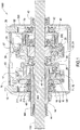
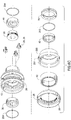
- Figure 1 is a cross sectional view of the transmission.
- the transmission consists of a first compound planetary gear set, a second compound planetary gear set, a first clutch, a second clutch, a first brake, a second brake, an output shaft, an input shaft, and a housing.
- the first compound planetary gear set comprises sun gear 10 having 81 teeth.
- the first compound planetary gear set further comprises pinion 11 having 29 teeth and pinion 12 having 13 teeth. Pinion 11 is engaged with sun 10. Pinion 12 is engaged with ring 13 having123 teeth.
- the second compound planetary gear set comprises sun 20 having 81 teeth.
- the second compound planetary gear set further comprises pinion 23 having 25 teeth and pinion 24 having 15 teeth. Pinion 23 is engaged with sun 20. Pinion 24 is engaged with ring 25 having 121 teeth.
- the output of the first planetary gear set is ring 13 which is fixedly attached to planet carrier 26 which his part of the second compound planetary gear set.
- the input for the first compound planetary gear set is carrier 14.
- the input for the second compound planetary gear set is carrier 26.
- the output for the second compound planetary gear set is sun 20. Sun 20 is fixedly attached to the transmission output shaft 100.
- Brake 16 is operationally positioned between sun 10 and the housing 200.
- Brake 27 is operationally positioned between ring 25 and the housing 200.
- Clutch 17 is operationally between carrier 14 and ring 13.
- Clutch 28 is operationally between carrier 26 and ring 25.
- Bearing 19 is disposed between shift fork 18 and carrier 14 (input shaft).
- Bearing 40 is disposed between sun 10 and carrier 14.
- Bearing 30 is disposed between carrier 26 and output shaft 100.
- Bearing 41 is disposed between carrier 26 and output shaft 100.
- Bearing 42 is disposed between ring 25 and shift fork 29.
- Bearing 43 is disposed between housing 200 and output shaft 100. Needle bearings 44, 45 are disposed between carrier 14 and output shaft 100.
- Bearing 46 is disposed between housing 200 and carrier 14.
- Bearing 62 is disposed between ring 25 and carrier 26.
- Spacer 205 is disposed between bearings 19 and 40.
- Clutch 17 is operationally disposed to engage and disengage between carrier 14 and carrier 26.
- an actuator (not shown) moves shift fork 18 thereby moving bearing carrier 71 which in turn forces carrier 14 to move axially thereby engaging clutch 17 with carrier 26. This effectively locks the first compound planetary gear set forcing the transmission ratio to 1:1.
- an actuator moves shift fork 29 thereby moving bearing carrier 70 which in turn forces carrier 250 to move axially which forces clutch 28 to engage carrier 26.
- Bearings 30 and 41 are keyed to shaft 100, thereby locating carrier 26 to prevent axial movement by carrier 26.
- Band brake 16 engages a brake portion 101 of sun 10.
- Band brake 27 engages a brake portion 251 of carrier 250.
- an actuator moves one end of band brake 16 thereby engaging the brake with portion 101 to stop sun 10.
- an actuator moves one end of band brake 27 thereby engaging the brake with portion 251 and stopping carrier 250.
- the band brakes 16, 27 are arranged such that the band winds tighter as the engaged components rotate. This arrangement requires very small forces to actuate the brake. The actuator simply pushes the end of each band against the rotating component at which time the band grabs and winds tight, stopping the rotating component.
- compound planets (11,12) and planets (23,24) enables an overall reduction in the size of the two compound planetary gear sets. For example, in order to obtain the same ratio of the first gear set while maintaining a sun having 81 teeth, the planet and ring would require gears of 97 teeth and 275 teeth respectively.
- the compound arrangement also enables a level of freedom in arrangement. For example, the compound planet may be reversed axially allowing an alternate placement of the ring gear. Such a change may enable a better assembly process.
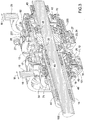
- Figure 2 is a perspective cross section view of Figure 1 .
- Snap rings 201, 202 engage shaft 100.
- Snap rings 203, 204 engage carrier 26.
- Bearings 30 and 41 are retained between snap rings 201, 202, 203, 204.
- Sun gear 20 is retained between bearings 30, 41. This arrangement retains carrier 26 in a fixed axial position with respect to shaft 100.
- FIG. 3 is a perspective cross section view of the compound planetary gear sets.
- Carrier 250 comprises ring 25 and portion 251 for engaging brake 27. Shift fork 18 and shift fork 29 each move pivotally in an axial direction (M), thereby engaging and disengaging clutch 17 and clutch 28 respectively.
- Figure 4 is a perspective view of the compound planetary gear sets.
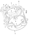
- FIG. 5 is a perspective view of the brakes.
- Brake 27 is attached to the housing 200 at a fixed point 50.
- Brake 16 is attached to the housing 200 at a fixed point 51.
- Shift fork 29 pivots about a pivot 52 and pivot 53.
- Shift fork 18 pivots about a pivot 54 and pivot 55.
- Pins 56 and 57 on shift fork 29 engage a bearing carrier 70.
- Pins 58 and 59 on shift fork 18 engage a bearing carrier 71.
- Bearing carrier 70 has a "U” shaped profile to accommodate pins 56, 57.
- Bearing carrier 71 has a "U” shaped profile to accommodate pins 58, 59.
- An actuator connects to an end 60 of brake 27.
- An actuator connects to an end 61 of brake 16.
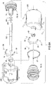
- Figure 6a , 6b and 6c are exploded views of the transmission.
- Figure 6b is a view of the first compound planetary gear set.
- Figure 6c is a view of the second compound planetary gear set.
- snap ring 210 retains bearing 19 in bearing carrier 71.
- Snap ring 211 retains bearing 40 in sun 10.
- snap ring 203 retains bearing 30 in carrier 26.
- Snap ring 204 retains bearing 41 in carrier 26.
- Snap ring 212 retains bearing 42 in bearing carrier 70.
- an actuator moves shift fork 18 which in turn forces carrier 14 to move axially, thereby engaging carrier 14 with clutch 17. This effectively locks the planetary assembly attached to carrier 14 forcing the first planetary gear ratio to 1:1.
- an actuator moves shift fork 29 which in turn forces ring 25 to move axially which causes clutch 28 to be engaged.
- an actuator moves one end of the band brake, thereby engaging the brake and stopping the respective carrier engaging the respective planetary set.
- Each brake is configured such that the band winds tighter as the carrier rotates.
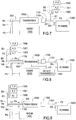
- FIG. 7 is a schematic system using the inventive transmission.
- a slip clutch 1100 is connected to the output shaft 100 of the transmission.
- engine 1400 drives input shaft 300 through a pulley P5, a belt B4 and a pulley P4.
- the diameter of each pulley P5 and P4 can be varied to provide a desired ratio.
- a slip clutch output shaft 1101 engages a pulley P1 and P2.
- a belt B1 is trained between P1 and pulley P3.
- a belt B3 is trained between pulley P2 and a flywheel 1200 input.
- Pulley P3 is connected to an alternator input shaft 1302.
- a belt B2 is trained between each accessory, namely, a power steering pump (P_S) 1300, an air conditioning pump (A_C) 1301, and an alternator (Alt) 1302.
- transmission 1000 can be used to select a desired gear ratio to optimize operation of the accessories.
- the accessories are driven through belts B1 and B2.
- Slip clutch 1100 provides a soft coupling between the engine and the accessories for start ups.
- the flywheel In a second operating mode the flywheel is used to drive the accessories. In this mode the slip clutch is disengaged and the accessories are driven through belts B3, B2 and B1. Engine 1400 may operate at idle or be shut down.
- Figure 8 is a schematic system using the inventive transmission. Unlike the embodiment in Figure 7 , the accessories in this embodiment are driven from the opposite side of the transmission 1000.
- the shafts 100 and 300 are coaxial.
- Pulley P6 is connected to shaft 100. Pulley P4 is connected to input shaft 300 which is carrier 14. Belt B1 is trained between pulley P6 and pulley P3. Belt B4 is trained between pulley P5 and P4.
- a vehicle transmission 1401 is connected to the engine 1400, typically to an engine crankshaft.
- the vehicle transmission 1401 is used to drive transmission 1000.
- this can be accomplished with a chain C1 engaged with the transmission torque converter.
- C1 is mechanically connected to the input shaft 300.
- Clutch 1100 is connected to shaft 100. Clutch 1100 is used to engage and disengage the flywheel from the transmission, and thereby from the accessories and engine.
- the advantage of taking the power off the transmission torque converter is that it allows the engine 1400 to stop while still maintaining the ability to recover regenerative braking power.
- This configuration also enables the engine to be started with the flywheel 1200 while taking power off the transmission 1401.
- Clutch 1102 allows disconnection of the engine when the engine is shut off for configurations drawing power off the vehicle transmission 1401, for example during a braking event. Clutch 1102 is used to engage or disengage engine 1400 from transmission 1000.
- Figure 9 is a schematic system using the inventive transmission.
- the configuration in Figure 9 is the same as described in Figure 8 , with the exception the vehicle transmission 1401 is absent.
- the novel features of this device and the described configurations include but are not limited to 1) the overall final drive ratio of the accessory drive is selected so the final speeds of the accessory drive can be either faster or slower than engine speed, as opposed to when the accessories are driven directly from the engine crankshaft output pulley, 2) the power taken from the vehicle can be taken from the engine or from the vehicle transmission, 3) the inventive device allows the power output to be in the front, rear, or next to the engine, 4) the input and output shafts are coaxial allowing power to be output from either end of the device, 5) the inventive device allows the engine to be shut off during braking events, 6) the inventive device allows the engine to be started with power stored in the flywheel, and 7) the inventive device allows the engine to be shut off while continuously maintaining power supply or other vehicle functions including the accessory drive.
Landscapes
- Engineering & Computer Science (AREA)
- General Engineering & Computer Science (AREA)
- Mechanical Engineering (AREA)
- Chemical & Material Sciences (AREA)
- Combustion & Propulsion (AREA)
- Transportation (AREA)
- Automation & Control Theory (AREA)
- Structure Of Transmissions (AREA)
- Auxiliary Drives, Propulsion Controls, And Safety Devices (AREA)
- Transmission Devices (AREA)
- Connection Of Motors, Electrical Generators, Mechanical Devices, And The Like (AREA)
Applications Claiming Priority (2)
| Application Number | Priority Date | Filing Date | Title |
|---|---|---|---|
| US13/440,474 US8444526B1 (en) | 2012-04-05 | 2012-04-05 | Multi-ratio planetary gear transmission |
| PCT/US2013/034098 WO2013151843A1 (en) | 2012-04-05 | 2013-03-27 | Multi-ratio planetary gear transmission |
Publications (2)
| Publication Number | Publication Date |
|---|---|
| EP2834536A1 EP2834536A1 (en) | 2015-02-11 |
| EP2834536B1 true EP2834536B1 (en) | 2018-12-12 |
Family
ID=48048315
Family Applications (1)
| Application Number | Title | Priority Date | Filing Date |
|---|---|---|---|
| EP13714521.5A Active EP2834536B1 (en) | 2012-04-05 | 2013-03-27 | Multi-ratio planetary gear transmission |
Country Status (9)
| Country | Link |
|---|---|
| US (1) | US8444526B1 (enExample) |
| EP (1) | EP2834536B1 (enExample) |
| JP (1) | JP6034953B2 (enExample) |
| KR (1) | KR101661833B1 (enExample) |
| CN (1) | CN104271987B (enExample) |
| BR (1) | BR112014024629B1 (enExample) |
| IN (1) | IN2014DN08679A (enExample) |
| RU (1) | RU2598469C2 (enExample) |
| WO (1) | WO2013151843A1 (enExample) |
Families Citing this family (4)
| Publication number | Priority date | Publication date | Assignee | Title |
|---|---|---|---|---|
| US11185015B2 (en) * | 2015-11-18 | 2021-11-30 | Techtronic Cordless Gp | Hedge trimmer with a dual gear setting |
| DE102016202726B4 (de) * | 2016-02-23 | 2018-01-11 | Schaeffler Technologies AG & Co. KG | Hochübersetzende Schaltgetriebeeinrichtung, insbesondere für ein elektrisch betriebenes Kraftfahrzeug |
| DE102018208382B4 (de) * | 2018-05-28 | 2025-04-30 | Zf Friedrichshafen Ag | Tretlagergetriebe in Planetenbauweise für ein Fahrrad oder Pedelec |
| CN111237143B (zh) * | 2020-01-09 | 2022-12-23 | 蒋定国 | 具有一轴带动多轴轮式发电装置的车辆 |
Citations (2)
| Publication number | Priority date | Publication date | Assignee | Title |
|---|---|---|---|---|
| US2827805A (en) * | 1957-01-18 | 1958-03-25 | Clark Equipment Co | Five speed transmission employing compound planetary gear sets |
| JP2007263377A (ja) * | 2007-07-20 | 2007-10-11 | Toyota Motor Corp | 車両用自動変速機 |
Family Cites Families (21)
| Publication number | Priority date | Publication date | Assignee | Title |
|---|---|---|---|---|
| US594195A (en) * | 1897-11-23 | gk cooee | ||
| US2069408A (en) * | 1935-07-31 | 1937-02-02 | Forichon Alphonse | Transmission |
| US2101233A (en) * | 1937-03-06 | 1937-12-07 | Bancroft Charles | Variable transmission means |
| DE1027998B (de) * | 1955-02-16 | 1958-04-10 | Borg Warner | Umlaufraedergetriebe fuer Kraftfahrzeuge mit zwei Umlaufraedersaetzen |
| US3263663A (en) * | 1963-09-09 | 1966-08-02 | Crusader Marine Corp | Engine |
| US4393964A (en) * | 1979-03-23 | 1983-07-19 | Ipanema Company | Hybrid power system and method for operating same |
| JPS5839326U (ja) * | 1981-09-08 | 1983-03-15 | 日産自動車株式会社 | 車両用エネルギ回収装置 |
| EP0326188B1 (en) * | 1983-11-04 | 1992-06-17 | Nissan Motor Co., Ltd. | Electronic control system for internal combustion engine with stall preventive feature and method for performing stall preventive engine control |
| RU2288391C2 (ru) * | 2002-04-18 | 2006-11-27 | Открытое акционерное общество "Всероссийский научно-исследовательский институт транспортного машиностроения" | Коробка передач |
| US6786845B1 (en) * | 2003-03-18 | 2004-09-07 | General Motors Corporation | Multi-speed power transmission |
| JP4269992B2 (ja) | 2004-03-24 | 2009-05-27 | トヨタ自動車株式会社 | 車両用遊星歯車式多段変速機 |
| KR100610794B1 (ko) * | 2004-09-07 | 2006-08-09 | 현대자동차주식회사 | 자동변속기의 6속 파워 트레인 |
| DE102006006645A1 (de) | 2006-02-14 | 2007-08-23 | Zf Friedrichshafen Ag | Mehrstufengetriebe |
| DE102006013371B4 (de) | 2006-03-23 | 2012-03-22 | Zf Friedrichshafen Ag | Mehrstufengetriebe |
| JP5138776B2 (ja) * | 2007-07-17 | 2013-02-06 | ルノー・トラックス | 最適化されたエネルギ回収システムを備えるパワートレイン |
| RU2008136621A (ru) * | 2008-09-11 | 2010-03-20 | Сергей Аркадьевич Веденеев (RU) | Автоматический зубчатый вариатор, изменяющий передаточное отношение без вывода шестерней из зацепления без устройств управления и с ними |
| JP5244641B2 (ja) | 2009-02-12 | 2013-07-24 | 本田技研工業株式会社 | 自動変速機 |
| GB2469864A (en) * | 2009-05-01 | 2010-11-03 | Ford Global Tech Llc | Hybrid vehicle and control method |
| JP4947124B2 (ja) * | 2009-11-05 | 2012-06-06 | 株式会社デンソー | 車載動力伝達システム |
| US20110177911A1 (en) * | 2010-01-20 | 2011-07-21 | Alexander Serkh | Planetary gear mechanism for a bicycle |
| RU2010107092A (ru) * | 2010-02-25 | 2011-08-27 | Джи Эм Глоубал Текнолоджи Оперейшнз, Инк. (Us) | Многоступенчатая планетарная коробка передач с двумя блоками двухступенчатых планетарных зубчатых передач |
-
2012
- 2012-04-05 US US13/440,474 patent/US8444526B1/en active Active
-
2013
- 2013-03-27 CN CN201380022941.9A patent/CN104271987B/zh active Active
- 2013-03-27 WO PCT/US2013/034098 patent/WO2013151843A1/en not_active Ceased
- 2013-03-27 KR KR1020147030030A patent/KR101661833B1/ko active Active
- 2013-03-27 EP EP13714521.5A patent/EP2834536B1/en active Active
- 2013-03-27 RU RU2014144267/11A patent/RU2598469C2/ru not_active IP Right Cessation
- 2013-03-27 JP JP2015504628A patent/JP6034953B2/ja active Active
- 2013-03-27 IN IN8679DEN2014 patent/IN2014DN08679A/en unknown
- 2013-03-27 BR BR112014024629-7A patent/BR112014024629B1/pt active IP Right Grant
Patent Citations (2)
| Publication number | Priority date | Publication date | Assignee | Title |
|---|---|---|---|---|
| US2827805A (en) * | 1957-01-18 | 1958-03-25 | Clark Equipment Co | Five speed transmission employing compound planetary gear sets |
| JP2007263377A (ja) * | 2007-07-20 | 2007-10-11 | Toyota Motor Corp | 車両用自動変速機 |
Also Published As
| Publication number | Publication date |
|---|---|
| KR101661833B1 (ko) | 2016-09-30 |
| BR112014024629A2 (enExample) | 2017-06-20 |
| BR112014024629B1 (pt) | 2021-11-16 |
| CN104271987B (zh) | 2017-03-08 |
| US8444526B1 (en) | 2013-05-21 |
| RU2014144267A (ru) | 2016-05-27 |
| WO2013151843A1 (en) | 2013-10-10 |
| RU2598469C2 (ru) | 2016-09-27 |
| IN2014DN08679A (enExample) | 2015-05-22 |
| JP6034953B2 (ja) | 2016-11-30 |
| KR20140139091A (ko) | 2014-12-04 |
| EP2834536A1 (en) | 2015-02-11 |
| JP2015514193A (ja) | 2015-05-18 |
| CN104271987A (zh) | 2015-01-07 |
Similar Documents
| Publication | Publication Date | Title |
|---|---|---|
| US10323576B2 (en) | Compact structure for accessory gearbox of an aircraft turbine engine | |
| EP2853779B1 (en) | Vehicle power transmission device | |
| EP0716947B1 (en) | Hybrid power transmission | |
| US8007396B2 (en) | Planetary transmission having common carrier for generating six forward and two reverse drive ratios | |
| EP3207286B1 (en) | Split power infinitely variable transmission architecture incorporating a planetary type ball variator with multiple fixed ranges | |
| KR20020070482A (ko) | 육상 차량, 특히 자동차용 변속 장치 | |
| US20150167802A1 (en) | Power transmission unit for vehicle | |
| EP0939867B1 (en) | Continuously variable transmission | |
| US7238135B2 (en) | Three-mode continuously variable transmission with a direct low mode and two split path high modes | |
| JP2006046468A (ja) | 無段変速機 | |
| EP2834536B1 (en) | Multi-ratio planetary gear transmission | |
| KR100788102B1 (ko) | 분류식 무단 변속기 | |
| EP0905415A2 (en) | Dual mode continuously variable transmission | |
| EP0905414A2 (en) | Dual mode continuously variable transmission | |
| EP4603721A1 (en) | A transmission arrangement for an electrically propelled vehicle | |
| US9897178B2 (en) | Manipulatable epicyclic type clutch device coupled with hybrid power train | |
| JP3630131B2 (ja) | 自動変速機の入力回転伝動機構 | |
| KR101357718B1 (ko) | 유성기어식 변속기 | |
| WO2016061498A1 (en) | Split power continuously variable transmission architecture incorporating a planetary type ball variator with multiple fixed ranges | |
| JPH0721947Y2 (ja) | ベルト式無段変速装置 | |
| EP0710191B1 (en) | Power train of five-speed automatic transmission for vehicle | |
| JPH07167230A (ja) | 車両用自動変速装置 | |
| JPH06100256B2 (ja) | ベルト式無段変速装置 | |
| JPH04248048A (ja) | 自動変速機 | |
| JPH04316752A (ja) | 自動変速機 |
Legal Events
| Date | Code | Title | Description |
|---|---|---|---|
| PUAI | Public reference made under article 153(3) epc to a published international application that has entered the european phase |
Free format text: ORIGINAL CODE: 0009012 |
|
| 17P | Request for examination filed |
Effective date: 20141105 |
|
| AK | Designated contracting states |
Kind code of ref document: A1 Designated state(s): AL AT BE BG CH CY CZ DE DK EE ES FI FR GB GR HR HU IE IS IT LI LT LU LV MC MK MT NL NO PL PT RO RS SE SI SK SM TR |
|
| AX | Request for extension of the european patent |
Extension state: BA ME |
|
| DAX | Request for extension of the european patent (deleted) | ||
| RIN1 | Information on inventor provided before grant (corrected) |
Inventor name: WARD, PETER Inventor name: ALI, AMITIAZ Inventor name: SCHNEIDER, DEAN Inventor name: SERKH, ALEXANDER |
|
| GRAP | Despatch of communication of intention to grant a patent |
Free format text: ORIGINAL CODE: EPIDOSNIGR1 |
|
| STAA | Information on the status of an ep patent application or granted ep patent |
Free format text: STATUS: GRANT OF PATENT IS INTENDED |
|
| INTG | Intention to grant announced |
Effective date: 20180608 |
|
| GRAS | Grant fee paid |
Free format text: ORIGINAL CODE: EPIDOSNIGR3 |
|
| GRAJ | Information related to disapproval of communication of intention to grant by the applicant or resumption of examination proceedings by the epo deleted |
Free format text: ORIGINAL CODE: EPIDOSDIGR1 |
|
| GRAL | Information related to payment of fee for publishing/printing deleted |
Free format text: ORIGINAL CODE: EPIDOSDIGR3 |
|
| STAA | Information on the status of an ep patent application or granted ep patent |
Free format text: STATUS: REQUEST FOR EXAMINATION WAS MADE |
|
| RAP1 | Party data changed (applicant data changed or rights of an application transferred) |
Owner name: GATES CORPORATION |
|
| GRAR | Information related to intention to grant a patent recorded |
Free format text: ORIGINAL CODE: EPIDOSNIGR71 |
|
| STAA | Information on the status of an ep patent application or granted ep patent |
Free format text: STATUS: GRANT OF PATENT IS INTENDED |
|
| GRAA | (expected) grant |
Free format text: ORIGINAL CODE: 0009210 |
|
| STAA | Information on the status of an ep patent application or granted ep patent |
Free format text: STATUS: THE PATENT HAS BEEN GRANTED |
|
| INTC | Intention to grant announced (deleted) | ||
| AK | Designated contracting states |
Kind code of ref document: B1 Designated state(s): AL AT BE BG CH CY CZ DE DK EE ES FI FR GB GR HR HU IE IS IT LI LT LU LV MC MK MT NL NO PL PT RO RS SE SI SK SM TR |
|
| INTG | Intention to grant announced |
Effective date: 20181105 |
|
| REG | Reference to a national code |
Ref country code: GB Ref legal event code: FG4D |
|
| REG | Reference to a national code |
Ref country code: CH Ref legal event code: EP |
|
| REG | Reference to a national code |
Ref country code: AT Ref legal event code: REF Ref document number: 1076453 Country of ref document: AT Kind code of ref document: T Effective date: 20181215 |
|
| REG | Reference to a national code |
Ref country code: DE Ref legal event code: R096 Ref document number: 602013048086 Country of ref document: DE |
|
| REG | Reference to a national code |
Ref country code: IE Ref legal event code: FG4D |
|
| REG | Reference to a national code |
Ref country code: CH Ref legal event code: PK Free format text: BERICHTIGUNGEN |
|
| RIC2 | Information provided on ipc code assigned after grant |
Ipc: F02B 67/06 20060101ALI20131024BHEP Ipc: B60K 6/30 20071001ALI20131024BHEP Ipc: F16H 3/66 20060101AFI20131024BHEP |
|
| REG | Reference to a national code |
Ref country code: NL Ref legal event code: MP Effective date: 20181212 |
|
| REG | Reference to a national code |
Ref country code: LT Ref legal event code: MG4D |
|
| PG25 | Lapsed in a contracting state [announced via postgrant information from national office to epo] |
Ref country code: FI Free format text: LAPSE BECAUSE OF FAILURE TO SUBMIT A TRANSLATION OF THE DESCRIPTION OR TO PAY THE FEE WITHIN THE PRESCRIBED TIME-LIMIT Effective date: 20181212 Ref country code: BG Free format text: LAPSE BECAUSE OF FAILURE TO SUBMIT A TRANSLATION OF THE DESCRIPTION OR TO PAY THE FEE WITHIN THE PRESCRIBED TIME-LIMIT Effective date: 20190312 Ref country code: LT Free format text: LAPSE BECAUSE OF FAILURE TO SUBMIT A TRANSLATION OF THE DESCRIPTION OR TO PAY THE FEE WITHIN THE PRESCRIBED TIME-LIMIT Effective date: 20181212 Ref country code: NO Free format text: LAPSE BECAUSE OF FAILURE TO SUBMIT A TRANSLATION OF THE DESCRIPTION OR TO PAY THE FEE WITHIN THE PRESCRIBED TIME-LIMIT Effective date: 20190312 Ref country code: ES Free format text: LAPSE BECAUSE OF FAILURE TO SUBMIT A TRANSLATION OF THE DESCRIPTION OR TO PAY THE FEE WITHIN THE PRESCRIBED TIME-LIMIT Effective date: 20181212 Ref country code: LV Free format text: LAPSE BECAUSE OF FAILURE TO SUBMIT A TRANSLATION OF THE DESCRIPTION OR TO PAY THE FEE WITHIN THE PRESCRIBED TIME-LIMIT Effective date: 20181212 Ref country code: HR Free format text: LAPSE BECAUSE OF FAILURE TO SUBMIT A TRANSLATION OF THE DESCRIPTION OR TO PAY THE FEE WITHIN THE PRESCRIBED TIME-LIMIT Effective date: 20181212 |
|
| REG | Reference to a national code |
Ref country code: AT Ref legal event code: MK05 Ref document number: 1076453 Country of ref document: AT Kind code of ref document: T Effective date: 20181212 |
|
| PG25 | Lapsed in a contracting state [announced via postgrant information from national office to epo] |
Ref country code: AL Free format text: LAPSE BECAUSE OF FAILURE TO SUBMIT A TRANSLATION OF THE DESCRIPTION OR TO PAY THE FEE WITHIN THE PRESCRIBED TIME-LIMIT Effective date: 20181212 Ref country code: SE Free format text: LAPSE BECAUSE OF FAILURE TO SUBMIT A TRANSLATION OF THE DESCRIPTION OR TO PAY THE FEE WITHIN THE PRESCRIBED TIME-LIMIT Effective date: 20181212 Ref country code: GR Free format text: LAPSE BECAUSE OF FAILURE TO SUBMIT A TRANSLATION OF THE DESCRIPTION OR TO PAY THE FEE WITHIN THE PRESCRIBED TIME-LIMIT Effective date: 20190313 Ref country code: RS Free format text: LAPSE BECAUSE OF FAILURE TO SUBMIT A TRANSLATION OF THE DESCRIPTION OR TO PAY THE FEE WITHIN THE PRESCRIBED TIME-LIMIT Effective date: 20181212 |
|
| PG25 | Lapsed in a contracting state [announced via postgrant information from national office to epo] |
Ref country code: NL Free format text: LAPSE BECAUSE OF FAILURE TO SUBMIT A TRANSLATION OF THE DESCRIPTION OR TO PAY THE FEE WITHIN THE PRESCRIBED TIME-LIMIT Effective date: 20181212 |
|
| PG25 | Lapsed in a contracting state [announced via postgrant information from national office to epo] |
Ref country code: IT Free format text: LAPSE BECAUSE OF FAILURE TO SUBMIT A TRANSLATION OF THE DESCRIPTION OR TO PAY THE FEE WITHIN THE PRESCRIBED TIME-LIMIT Effective date: 20181212 Ref country code: PL Free format text: LAPSE BECAUSE OF FAILURE TO SUBMIT A TRANSLATION OF THE DESCRIPTION OR TO PAY THE FEE WITHIN THE PRESCRIBED TIME-LIMIT Effective date: 20181212 Ref country code: PT Free format text: LAPSE BECAUSE OF FAILURE TO SUBMIT A TRANSLATION OF THE DESCRIPTION OR TO PAY THE FEE WITHIN THE PRESCRIBED TIME-LIMIT Effective date: 20190412 Ref country code: CZ Free format text: LAPSE BECAUSE OF FAILURE TO SUBMIT A TRANSLATION OF THE DESCRIPTION OR TO PAY THE FEE WITHIN THE PRESCRIBED TIME-LIMIT Effective date: 20181212 |
|
| PG25 | Lapsed in a contracting state [announced via postgrant information from national office to epo] |
Ref country code: EE Free format text: LAPSE BECAUSE OF FAILURE TO SUBMIT A TRANSLATION OF THE DESCRIPTION OR TO PAY THE FEE WITHIN THE PRESCRIBED TIME-LIMIT Effective date: 20181212 Ref country code: IS Free format text: LAPSE BECAUSE OF FAILURE TO SUBMIT A TRANSLATION OF THE DESCRIPTION OR TO PAY THE FEE WITHIN THE PRESCRIBED TIME-LIMIT Effective date: 20190412 Ref country code: RO Free format text: LAPSE BECAUSE OF FAILURE TO SUBMIT A TRANSLATION OF THE DESCRIPTION OR TO PAY THE FEE WITHIN THE PRESCRIBED TIME-LIMIT Effective date: 20181212 Ref country code: SK Free format text: LAPSE BECAUSE OF FAILURE TO SUBMIT A TRANSLATION OF THE DESCRIPTION OR TO PAY THE FEE WITHIN THE PRESCRIBED TIME-LIMIT Effective date: 20181212 Ref country code: SM Free format text: LAPSE BECAUSE OF FAILURE TO SUBMIT A TRANSLATION OF THE DESCRIPTION OR TO PAY THE FEE WITHIN THE PRESCRIBED TIME-LIMIT Effective date: 20181212 |
|
| REG | Reference to a national code |
Ref country code: DE Ref legal event code: R097 Ref document number: 602013048086 Country of ref document: DE |
|
| PLBE | No opposition filed within time limit |
Free format text: ORIGINAL CODE: 0009261 |
|
| STAA | Information on the status of an ep patent application or granted ep patent |
Free format text: STATUS: NO OPPOSITION FILED WITHIN TIME LIMIT |
|
| PG25 | Lapsed in a contracting state [announced via postgrant information from national office to epo] |
Ref country code: DK Free format text: LAPSE BECAUSE OF FAILURE TO SUBMIT A TRANSLATION OF THE DESCRIPTION OR TO PAY THE FEE WITHIN THE PRESCRIBED TIME-LIMIT Effective date: 20181212 Ref country code: AT Free format text: LAPSE BECAUSE OF FAILURE TO SUBMIT A TRANSLATION OF THE DESCRIPTION OR TO PAY THE FEE WITHIN THE PRESCRIBED TIME-LIMIT Effective date: 20181212 Ref country code: SI Free format text: LAPSE BECAUSE OF FAILURE TO SUBMIT A TRANSLATION OF THE DESCRIPTION OR TO PAY THE FEE WITHIN THE PRESCRIBED TIME-LIMIT Effective date: 20181212 Ref country code: MC Free format text: LAPSE BECAUSE OF FAILURE TO SUBMIT A TRANSLATION OF THE DESCRIPTION OR TO PAY THE FEE WITHIN THE PRESCRIBED TIME-LIMIT Effective date: 20181212 |
|
| REG | Reference to a national code |
Ref country code: CH Ref legal event code: PL |
|
| 26N | No opposition filed |
Effective date: 20190913 |
|
| PG25 | Lapsed in a contracting state [announced via postgrant information from national office to epo] |
Ref country code: LU Free format text: LAPSE BECAUSE OF NON-PAYMENT OF DUE FEES Effective date: 20190327 |
|
| REG | Reference to a national code |
Ref country code: BE Ref legal event code: MM Effective date: 20190331 |
|
| PG25 | Lapsed in a contracting state [announced via postgrant information from national office to epo] |
Ref country code: IE Free format text: LAPSE BECAUSE OF NON-PAYMENT OF DUE FEES Effective date: 20190327 Ref country code: CH Free format text: LAPSE BECAUSE OF NON-PAYMENT OF DUE FEES Effective date: 20190331 Ref country code: LI Free format text: LAPSE BECAUSE OF NON-PAYMENT OF DUE FEES Effective date: 20190331 |
|
| PG25 | Lapsed in a contracting state [announced via postgrant information from national office to epo] |
Ref country code: BE Free format text: LAPSE BECAUSE OF NON-PAYMENT OF DUE FEES Effective date: 20190331 |
|
| PG25 | Lapsed in a contracting state [announced via postgrant information from national office to epo] |
Ref country code: TR Free format text: LAPSE BECAUSE OF FAILURE TO SUBMIT A TRANSLATION OF THE DESCRIPTION OR TO PAY THE FEE WITHIN THE PRESCRIBED TIME-LIMIT Effective date: 20181212 |
|
| PG25 | Lapsed in a contracting state [announced via postgrant information from national office to epo] |
Ref country code: MT Free format text: LAPSE BECAUSE OF NON-PAYMENT OF DUE FEES Effective date: 20190327 |
|
| PG25 | Lapsed in a contracting state [announced via postgrant information from national office to epo] |
Ref country code: CY Free format text: LAPSE BECAUSE OF FAILURE TO SUBMIT A TRANSLATION OF THE DESCRIPTION OR TO PAY THE FEE WITHIN THE PRESCRIBED TIME-LIMIT Effective date: 20181212 |
|
| PG25 | Lapsed in a contracting state [announced via postgrant information from national office to epo] |
Ref country code: HU Free format text: LAPSE BECAUSE OF FAILURE TO SUBMIT A TRANSLATION OF THE DESCRIPTION OR TO PAY THE FEE WITHIN THE PRESCRIBED TIME-LIMIT; INVALID AB INITIO Effective date: 20130327 |
|
| PG25 | Lapsed in a contracting state [announced via postgrant information from national office to epo] |
Ref country code: MK Free format text: LAPSE BECAUSE OF FAILURE TO SUBMIT A TRANSLATION OF THE DESCRIPTION OR TO PAY THE FEE WITHIN THE PRESCRIBED TIME-LIMIT Effective date: 20181212 |
|
| PGFP | Annual fee paid to national office [announced via postgrant information from national office to epo] |
Ref country code: DE Payment date: 20250218 Year of fee payment: 13 |
|
| PGFP | Annual fee paid to national office [announced via postgrant information from national office to epo] |
Ref country code: FR Payment date: 20250219 Year of fee payment: 13 |
|
| PGFP | Annual fee paid to national office [announced via postgrant information from national office to epo] |
Ref country code: GB Payment date: 20250221 Year of fee payment: 13 |