EP2834040B1 - Particules abrasives, procédé de fabrication de particules abrasives et articles abrasifs - Google Patents
Particules abrasives, procédé de fabrication de particules abrasives et articles abrasifs Download PDFInfo
- Publication number
- EP2834040B1 EP2834040B1 EP13772568.5A EP13772568A EP2834040B1 EP 2834040 B1 EP2834040 B1 EP 2834040B1 EP 13772568 A EP13772568 A EP 13772568A EP 2834040 B1 EP2834040 B1 EP 2834040B1
- Authority
- EP
- European Patent Office
- Prior art keywords
- shaped ceramic
- abrasive
- particle
- perimeter
- abrasive particles
- Prior art date
- Legal status (The legal status is an assumption and is not a legal conclusion. Google has not performed a legal analysis and makes no representation as to the accuracy of the status listed.)
- Active
Links
- 239000002245 particle Substances 0.000 title claims description 307
- 238000004519 manufacturing process Methods 0.000 title claims description 28
- 239000000919 ceramic Substances 0.000 claims description 153
- 239000012700 ceramic precursor Substances 0.000 claims description 91
- 238000000034 method Methods 0.000 claims description 69
- 239000000463 material Substances 0.000 claims description 50
- 230000002093 peripheral effect Effects 0.000 claims description 37
- PNEYBMLMFCGWSK-UHFFFAOYSA-N Alumina Chemical compound [O-2].[O-2].[O-2].[Al+3].[Al+3] PNEYBMLMFCGWSK-UHFFFAOYSA-N 0.000 claims description 32
- 230000001154 acute effect Effects 0.000 claims description 32
- 238000005245 sintering Methods 0.000 claims description 20
- 239000011230 binding agent Substances 0.000 claims description 16
- 229910010293 ceramic material Inorganic materials 0.000 claims description 12
- 239000000835 fiber Substances 0.000 claims description 12
- 238000001354 calcination Methods 0.000 claims description 11
- TWNQGVIAIRXVLR-UHFFFAOYSA-N oxo(oxoalumanyloxy)alumane Chemical compound O=[Al]O[Al]=O TWNQGVIAIRXVLR-UHFFFAOYSA-N 0.000 claims description 9
- MCMNRKCIXSYSNV-UHFFFAOYSA-N ZrO2 Inorganic materials O=[Zr]=O MCMNRKCIXSYSNV-UHFFFAOYSA-N 0.000 claims description 7
- 230000000717 retained effect Effects 0.000 claims description 6
- XHCLAFWTIXFWPH-UHFFFAOYSA-N [O-2].[O-2].[O-2].[O-2].[O-2].[V+5].[V+5] Chemical compound [O-2].[O-2].[O-2].[O-2].[O-2].[V+5].[V+5] XHCLAFWTIXFWPH-UHFFFAOYSA-N 0.000 claims description 5
- 229910001935 vanadium oxide Inorganic materials 0.000 claims description 5
- 229910000420 cerium oxide Inorganic materials 0.000 claims description 4
- BMMGVYCKOGBVEV-UHFFFAOYSA-N oxo(oxoceriooxy)cerium Chemical compound [Ce]=O.O=[Ce]=O BMMGVYCKOGBVEV-UHFFFAOYSA-N 0.000 claims description 4
- RVTZCBVAJQQJTK-UHFFFAOYSA-N oxygen(2-);zirconium(4+) Chemical compound [O-2].[O-2].[Zr+4] RVTZCBVAJQQJTK-UHFFFAOYSA-N 0.000 claims description 4
- 229910001928 zirconium oxide Inorganic materials 0.000 claims description 4
- 239000006185 dispersion Substances 0.000 description 47
- 230000000052 comparative effect Effects 0.000 description 32
- 238000000227 grinding Methods 0.000 description 27
- -1 poly(methyl methacrylate) Polymers 0.000 description 24
- 238000012360 testing method Methods 0.000 description 18
- 239000000203 mixture Substances 0.000 description 15
- 239000000654 additive Substances 0.000 description 14
- 238000000576 coating method Methods 0.000 description 14
- 239000002243 precursor Substances 0.000 description 13
- 101001092930 Homo sapiens Prosaposin Proteins 0.000 description 12
- 239000007788 liquid Substances 0.000 description 12
- VYPSYNLAJGMNEJ-UHFFFAOYSA-N Silicium dioxide Chemical compound O=[Si]=O VYPSYNLAJGMNEJ-UHFFFAOYSA-N 0.000 description 11
- XLYOFNOQVPJJNP-UHFFFAOYSA-N water Substances O XLYOFNOQVPJJNP-UHFFFAOYSA-N 0.000 description 11
- 239000011248 coating agent Substances 0.000 description 10
- 230000008569 process Effects 0.000 description 10
- 102100023792 ETS domain-containing protein Elk-4 Human genes 0.000 description 9
- 101000884714 Homo sapiens Beta-defensin 4A Proteins 0.000 description 9
- 101001048716 Homo sapiens ETS domain-containing protein Elk-4 Proteins 0.000 description 9
- 239000011521 glass Substances 0.000 description 9
- FAHBNUUHRFUEAI-UHFFFAOYSA-M hydroxidooxidoaluminium Chemical compound O[Al]=O FAHBNUUHRFUEAI-UHFFFAOYSA-M 0.000 description 9
- 229910052751 metal Inorganic materials 0.000 description 9
- 239000002184 metal Substances 0.000 description 9
- 229910000975 Carbon steel Inorganic materials 0.000 description 8
- CPLXHLVBOLITMK-UHFFFAOYSA-N Magnesium oxide Chemical compound [Mg]=O CPLXHLVBOLITMK-UHFFFAOYSA-N 0.000 description 8
- 238000001035 drying Methods 0.000 description 8
- 239000003082 abrasive agent Substances 0.000 description 7
- 229910001593 boehmite Inorganic materials 0.000 description 7
- 239000010962 carbon steel Substances 0.000 description 7
- OKKJLVBELUTLKV-UHFFFAOYSA-N Methanol Chemical compound OC OKKJLVBELUTLKV-UHFFFAOYSA-N 0.000 description 6
- GWEVSGVZZGPLCZ-UHFFFAOYSA-N Titan oxide Chemical compound O=[Ti]=O GWEVSGVZZGPLCZ-UHFFFAOYSA-N 0.000 description 6
- 230000000996 additive effect Effects 0.000 description 6
- 239000003795 chemical substances by application Substances 0.000 description 6
- WMWXXXSCZVGQAR-UHFFFAOYSA-N dialuminum;oxygen(2-);hydrate Chemical compound O.[O-2].[O-2].[O-2].[Al+3].[Al+3] WMWXXXSCZVGQAR-UHFFFAOYSA-N 0.000 description 6
- 230000000694 effects Effects 0.000 description 6
- 239000010963 304 stainless steel Substances 0.000 description 5
- 229910000589 SAE 304 stainless steel Inorganic materials 0.000 description 5
- 238000005299 abrasion Methods 0.000 description 5
- 239000006061 abrasive grain Substances 0.000 description 5
- 229910001610 cryolite Inorganic materials 0.000 description 5
- UQSXHKLRYXJYBZ-UHFFFAOYSA-N iron oxide Inorganic materials [Fe]=O UQSXHKLRYXJYBZ-UHFFFAOYSA-N 0.000 description 5
- 239000000377 silicon dioxide Substances 0.000 description 5
- 239000000243 solution Substances 0.000 description 5
- 239000000126 substance Substances 0.000 description 5
- 239000004094 surface-active agent Substances 0.000 description 5
- VTYYLEPIZMXCLO-UHFFFAOYSA-L Calcium carbonate Chemical compound [Ca+2].[O-]C([O-])=O VTYYLEPIZMXCLO-UHFFFAOYSA-L 0.000 description 4
- ODINCKMPIJJUCX-UHFFFAOYSA-N Calcium oxide Chemical compound [Ca]=O ODINCKMPIJJUCX-UHFFFAOYSA-N 0.000 description 4
- PXHVJJICTQNCMI-UHFFFAOYSA-N Nickel Chemical compound [Ni] PXHVJJICTQNCMI-UHFFFAOYSA-N 0.000 description 4
- 235000019483 Peanut oil Nutrition 0.000 description 4
- 239000004743 Polypropylene Substances 0.000 description 4
- 101150033179 SAP3 gene Proteins 0.000 description 4
- 101150106968 SAP8 gene Proteins 0.000 description 4
- 239000002253 acid Chemical class 0.000 description 4
- 239000002518 antifoaming agent Substances 0.000 description 4
- 239000003085 diluting agent Substances 0.000 description 4
- 239000000945 filler Substances 0.000 description 4
- 238000010438 heat treatment Methods 0.000 description 4
- 239000000395 magnesium oxide Substances 0.000 description 4
- 239000004579 marble Substances 0.000 description 4
- 239000006082 mold release agent Substances 0.000 description 4
- 239000000312 peanut oil Substances 0.000 description 4
- 229920000647 polyepoxide Polymers 0.000 description 4
- 229920001155 polypropylene Polymers 0.000 description 4
- 229910001404 rare earth metal oxide Inorganic materials 0.000 description 4
- 229920005989 resin Polymers 0.000 description 4
- 239000011347 resin Substances 0.000 description 4
- BBIKPGRUAMIMIA-UHFFFAOYSA-N sapb Chemical compound C1SCC(C(=O)NC(CC(N)=O)C(O)=O)NC(=O)C(C(C)O)NC(=O)C(C(C)O)NC(=O)C(C(C)CC)NC(=O)C(=C)NC(=O)C(CC(C)C)NC(=O)C(CO)NC(=O)C1NC(=O)C(CC(O)=O)NC(=O)CNC(=O)C1NC(=O)C(CC(C)C)NC(=O)C(CC(C)C)NC(=O)C(CC(C)C)NC(=O)C(=C)NC(=O)C(C)NC(=O)C(CCCNC(N)=N)NC(=O)C(NC(=O)CNC(=O)C(N)C(C)O)CSC1 BBIKPGRUAMIMIA-UHFFFAOYSA-N 0.000 description 4
- 229920001169 thermoplastic Polymers 0.000 description 4
- 239000012815 thermoplastic material Substances 0.000 description 4
- 239000004416 thermosoftening plastic Substances 0.000 description 4
- 239000002023 wood Substances 0.000 description 4
- QTBSBXVTEAMEQO-UHFFFAOYSA-N Acetic acid Chemical compound CC(O)=O QTBSBXVTEAMEQO-UHFFFAOYSA-N 0.000 description 3
- OKTJSMMVPCPJKN-UHFFFAOYSA-N Carbon Chemical compound [C] OKTJSMMVPCPJKN-UHFFFAOYSA-N 0.000 description 3
- 102100023794 ETS domain-containing protein Elk-3 Human genes 0.000 description 3
- 101001048720 Homo sapiens ETS domain-containing protein Elk-3 Proteins 0.000 description 3
- GRYLNZFGIOXLOG-UHFFFAOYSA-N Nitric acid Chemical compound O[N+]([O-])=O GRYLNZFGIOXLOG-UHFFFAOYSA-N 0.000 description 3
- KWYUFKZDYYNOTN-UHFFFAOYSA-M Potassium hydroxide Chemical compound [OH-].[K+] KWYUFKZDYYNOTN-UHFFFAOYSA-M 0.000 description 3
- 101150117794 SAP4 gene Proteins 0.000 description 3
- CDBYLPFSWZWCQE-UHFFFAOYSA-L Sodium Carbonate Chemical compound [Na+].[Na+].[O-]C([O-])=O CDBYLPFSWZWCQE-UHFFFAOYSA-L 0.000 description 3
- 239000002585 base Substances 0.000 description 3
- 239000011324 bead Substances 0.000 description 3
- 239000007822 coupling agent Substances 0.000 description 3
- 230000001186 cumulative effect Effects 0.000 description 3
- 230000007423 decrease Effects 0.000 description 3
- 239000010432 diamond Substances 0.000 description 3
- 229910003460 diamond Inorganic materials 0.000 description 3
- 239000003822 epoxy resin Substances 0.000 description 3
- 230000008020 evaporation Effects 0.000 description 3
- 238000001704 evaporation Methods 0.000 description 3
- 238000011049 filling Methods 0.000 description 3
- 239000010439 graphite Substances 0.000 description 3
- 229910002804 graphite Inorganic materials 0.000 description 3
- MRELNEQAGSRDBK-UHFFFAOYSA-N lanthanum oxide Inorganic materials [O-2].[O-2].[O-2].[La+3].[La+3] MRELNEQAGSRDBK-UHFFFAOYSA-N 0.000 description 3
- 239000000314 lubricant Substances 0.000 description 3
- 229910044991 metal oxide Inorganic materials 0.000 description 3
- 150000004706 metal oxides Chemical class 0.000 description 3
- 238000002156 mixing Methods 0.000 description 3
- 229910017604 nitric acid Inorganic materials 0.000 description 3
- 239000002667 nucleating agent Substances 0.000 description 3
- KTUFCUMIWABKDW-UHFFFAOYSA-N oxo(oxolanthaniooxy)lanthanum Chemical compound O=[La]O[La]=O KTUFCUMIWABKDW-UHFFFAOYSA-N 0.000 description 3
- 229920001568 phenolic resin Polymers 0.000 description 3
- 239000011148 porous material Substances 0.000 description 3
- 239000000843 powder Substances 0.000 description 3
- 150000003839 salts Chemical class 0.000 description 3
- 239000007787 solid Substances 0.000 description 3
- 239000010935 stainless steel Substances 0.000 description 3
- 229910001220 stainless steel Inorganic materials 0.000 description 3
- 229920001187 thermosetting polymer Polymers 0.000 description 3
- 230000009466 transformation Effects 0.000 description 3
- RUDFQVOCFDJEEF-UHFFFAOYSA-N yttrium(III) oxide Inorganic materials [O-2].[O-2].[O-2].[Y+3].[Y+3] RUDFQVOCFDJEEF-UHFFFAOYSA-N 0.000 description 3
- PSVRFUPOQYJOOZ-QNPWAGBNSA-N 1-stearoyl-2-arachidonoyl-sn-glycero-3-phosphocholine Chemical compound CCCCCCCCCCCCCCCCCC(=O)OC[C@H](COP([O-])(=O)OCC[N+](C)(C)C)OC(=O)CCC\C=C/C\C=C/C\C=C/C\C=C/CCCCC PSVRFUPOQYJOOZ-QNPWAGBNSA-N 0.000 description 2
- OSWFIVFLDKOXQC-UHFFFAOYSA-N 4-(3-methoxyphenyl)aniline Chemical compound COC1=CC=CC(C=2C=CC(N)=CC=2)=C1 OSWFIVFLDKOXQC-UHFFFAOYSA-N 0.000 description 2
- 101100476202 Caenorhabditis elegans mog-2 gene Proteins 0.000 description 2
- VYZAMTAEIAYCRO-UHFFFAOYSA-N Chromium Chemical compound [Cr] VYZAMTAEIAYCRO-UHFFFAOYSA-N 0.000 description 2
- VEXZGXHMUGYJMC-UHFFFAOYSA-N Hydrochloric acid Chemical compound Cl VEXZGXHMUGYJMC-UHFFFAOYSA-N 0.000 description 2
- XEEYBQQBJWHFJM-UHFFFAOYSA-N Iron Chemical compound [Fe] XEEYBQQBJWHFJM-UHFFFAOYSA-N 0.000 description 2
- FYYHWMGAXLPEAU-UHFFFAOYSA-N Magnesium Chemical compound [Mg] FYYHWMGAXLPEAU-UHFFFAOYSA-N 0.000 description 2
- TWRXJAOTZQYOKJ-UHFFFAOYSA-L Magnesium chloride Chemical compound [Mg+2].[Cl-].[Cl-] TWRXJAOTZQYOKJ-UHFFFAOYSA-L 0.000 description 2
- WCUXLLCKKVVCTQ-UHFFFAOYSA-M Potassium chloride Chemical compound [Cl-].[K+] WCUXLLCKKVVCTQ-UHFFFAOYSA-M 0.000 description 2
- 108010084592 Saporins Proteins 0.000 description 2
- FAPWRFPIFSIZLT-UHFFFAOYSA-M Sodium chloride Chemical compound [Na+].[Cl-] FAPWRFPIFSIZLT-UHFFFAOYSA-M 0.000 description 2
- 229910000831 Steel Inorganic materials 0.000 description 2
- RTAQQCXQSZGOHL-UHFFFAOYSA-N Titanium Chemical compound [Ti] RTAQQCXQSZGOHL-UHFFFAOYSA-N 0.000 description 2
- XLOMVQKBTHCTTD-UHFFFAOYSA-N Zinc monoxide Chemical compound [Zn]=O XLOMVQKBTHCTTD-UHFFFAOYSA-N 0.000 description 2
- YKTSYUJCYHOUJP-UHFFFAOYSA-N [O--].[Al+3].[Al+3].[O-][Si]([O-])([O-])[O-] Chemical compound [O--].[Al+3].[Al+3].[O-][Si]([O-])([O-])[O-] YKTSYUJCYHOUJP-UHFFFAOYSA-N 0.000 description 2
- 229910000272 alkali metal oxide Inorganic materials 0.000 description 2
- 239000012298 atmosphere Substances 0.000 description 2
- TZCXTZWJZNENPQ-UHFFFAOYSA-L barium sulfate Chemical compound [Ba+2].[O-]S([O-])(=O)=O TZCXTZWJZNENPQ-UHFFFAOYSA-L 0.000 description 2
- 229910000019 calcium carbonate Inorganic materials 0.000 description 2
- 239000000292 calcium oxide Substances 0.000 description 2
- 235000012255 calcium oxide Nutrition 0.000 description 2
- 235000012241 calcium silicate Nutrition 0.000 description 2
- 229910052918 calcium silicate Inorganic materials 0.000 description 2
- OSGAYBCDTDRGGQ-UHFFFAOYSA-L calcium sulfate Chemical compound [Ca+2].[O-]S([O-])(=O)=O OSGAYBCDTDRGGQ-UHFFFAOYSA-L 0.000 description 2
- OYACROKNLOSFPA-UHFFFAOYSA-N calcium;dioxido(oxo)silane Chemical compound [Ca+2].[O-][Si]([O-])=O OYACROKNLOSFPA-UHFFFAOYSA-N 0.000 description 2
- 239000006229 carbon black Substances 0.000 description 2
- 230000008859 change Effects 0.000 description 2
- RNFNDJAIBTYOQL-UHFFFAOYSA-N chloral hydrate Chemical compound OC(O)C(Cl)(Cl)Cl RNFNDJAIBTYOQL-UHFFFAOYSA-N 0.000 description 2
- 229910017052 cobalt Inorganic materials 0.000 description 2
- 239000010941 cobalt Substances 0.000 description 2
- GUTLYIVDDKVIGB-UHFFFAOYSA-N cobalt atom Chemical compound [Co] GUTLYIVDDKVIGB-UHFFFAOYSA-N 0.000 description 2
- 150000001875 compounds Chemical class 0.000 description 2
- 238000010276 construction Methods 0.000 description 2
- 238000013461 design Methods 0.000 description 2
- 239000004744 fabric Substances 0.000 description 2
- 239000010440 gypsum Substances 0.000 description 2
- 229910052602 gypsum Inorganic materials 0.000 description 2
- 238000005470 impregnation Methods 0.000 description 2
- 229910052749 magnesium Inorganic materials 0.000 description 2
- 239000011777 magnesium Substances 0.000 description 2
- 239000002923 metal particle Substances 0.000 description 2
- 150000002739 metals Chemical class 0.000 description 2
- BDAGIHXWWSANSR-UHFFFAOYSA-N methanoic acid Natural products OC=O BDAGIHXWWSANSR-UHFFFAOYSA-N 0.000 description 2
- 229910052759 nickel Inorganic materials 0.000 description 2
- 239000003921 oil Substances 0.000 description 2
- 235000019198 oils Nutrition 0.000 description 2
- 229920000620 organic polymer Polymers 0.000 description 2
- 239000011236 particulate material Substances 0.000 description 2
- 239000005011 phenolic resin Substances 0.000 description 2
- 238000005498 polishing Methods 0.000 description 2
- 229920000728 polyester Polymers 0.000 description 2
- 229920000642 polymer Polymers 0.000 description 2
- 229920000098 polyolefin Polymers 0.000 description 2
- 239000004800 polyvinyl chloride Substances 0.000 description 2
- 229920000915 polyvinyl chloride Polymers 0.000 description 2
- 230000005855 radiation Effects 0.000 description 2
- 150000004760 silicates Chemical class 0.000 description 2
- 239000002002 slurry Substances 0.000 description 2
- 239000010959 steel Substances 0.000 description 2
- 239000004575 stone Substances 0.000 description 2
- 239000000758 substrate Substances 0.000 description 2
- 239000010936 titanium Substances 0.000 description 2
- 229910052719 titanium Inorganic materials 0.000 description 2
- 239000001993 wax Substances 0.000 description 2
- 239000000080 wetting agent Substances 0.000 description 2
- JRZKNHITLINYHV-UHFFFAOYSA-N 1,2,3,4,5-pentachloronaphthalene Chemical compound ClC1=CC=CC2=C(Cl)C(Cl)=C(Cl)C(Cl)=C21 JRZKNHITLINYHV-UHFFFAOYSA-N 0.000 description 1
- NAQWICRLNQSPPW-UHFFFAOYSA-N 1,2,3,4-tetrachloronaphthalene Chemical compound C1=CC=CC2=C(Cl)C(Cl)=C(Cl)C(Cl)=C21 NAQWICRLNQSPPW-UHFFFAOYSA-N 0.000 description 1
- KUBDPQJOLOUJRM-UHFFFAOYSA-N 2-(chloromethyl)oxirane;4-[2-(4-hydroxyphenyl)propan-2-yl]phenol Chemical compound ClCC1CO1.C=1C=C(O)C=CC=1C(C)(C)C1=CC=C(O)C=C1 KUBDPQJOLOUJRM-UHFFFAOYSA-N 0.000 description 1
- KXGFMDJXCMQABM-UHFFFAOYSA-N 2-methoxy-6-methylphenol Chemical compound [CH]OC1=CC=CC([CH])=C1O KXGFMDJXCMQABM-UHFFFAOYSA-N 0.000 description 1
- NIXOWILDQLNWCW-UHFFFAOYSA-M Acrylate Chemical compound [O-]C(=O)C=C NIXOWILDQLNWCW-UHFFFAOYSA-M 0.000 description 1
- QGZKDVFQNNGYKY-UHFFFAOYSA-O Ammonium Chemical compound [NH4+] QGZKDVFQNNGYKY-UHFFFAOYSA-O 0.000 description 1
- 229910052580 B4C Inorganic materials 0.000 description 1
- 229910052582 BN Inorganic materials 0.000 description 1
- PZNSFCLAULLKQX-UHFFFAOYSA-N Boron nitride Chemical compound N#B PZNSFCLAULLKQX-UHFFFAOYSA-N 0.000 description 1
- 229910021532 Calcite Inorganic materials 0.000 description 1
- 229910052684 Cerium Inorganic materials 0.000 description 1
- 229910052692 Dysprosium Inorganic materials 0.000 description 1
- 239000004593 Epoxy Substances 0.000 description 1
- 229910052691 Erbium Inorganic materials 0.000 description 1
- LFQSCWFLJHTTHZ-UHFFFAOYSA-N Ethanol Chemical compound CCO LFQSCWFLJHTTHZ-UHFFFAOYSA-N 0.000 description 1
- JOYRKODLDBILNP-UHFFFAOYSA-N Ethyl urethane Chemical compound CCOC(N)=O JOYRKODLDBILNP-UHFFFAOYSA-N 0.000 description 1
- 229910052688 Gadolinium Inorganic materials 0.000 description 1
- 229910000760 Hardened steel Inorganic materials 0.000 description 1
- DGAQECJNVWCQMB-PUAWFVPOSA-M Ilexoside XXIX Chemical compound C[C@@H]1CC[C@@]2(CC[C@@]3(C(=CC[C@H]4[C@]3(CC[C@@H]5[C@@]4(CC[C@@H](C5(C)C)OS(=O)(=O)[O-])C)C)[C@@H]2[C@]1(C)O)C)C(=O)O[C@H]6[C@@H]([C@H]([C@@H]([C@H](O6)CO)O)O)O.[Na+] DGAQECJNVWCQMB-PUAWFVPOSA-M 0.000 description 1
- 235000019738 Limestone Nutrition 0.000 description 1
- 229920000877 Melamine resin Polymers 0.000 description 1
- 229910002651 NO3 Inorganic materials 0.000 description 1
- 229910000503 Na-aluminosilicate Inorganic materials 0.000 description 1
- KKCBUQHMOMHUOY-UHFFFAOYSA-N Na2O Inorganic materials [O-2].[Na+].[Na+] KKCBUQHMOMHUOY-UHFFFAOYSA-N 0.000 description 1
- 229910052779 Neodymium Inorganic materials 0.000 description 1
- NHNBFGGVMKEFGY-UHFFFAOYSA-N Nitrate Chemical compound [O-][N+]([O-])=O NHNBFGGVMKEFGY-UHFFFAOYSA-N 0.000 description 1
- MXRIRQGCELJRSN-UHFFFAOYSA-N O.O.O.[Al] Chemical compound O.O.O.[Al] MXRIRQGCELJRSN-UHFFFAOYSA-N 0.000 description 1
- 240000007817 Olea europaea Species 0.000 description 1
- 239000004952 Polyamide Substances 0.000 description 1
- 239000004698 Polyethylene Substances 0.000 description 1
- 239000004793 Polystyrene Substances 0.000 description 1
- ZLMJMSJWJFRBEC-UHFFFAOYSA-N Potassium Chemical compound [K] ZLMJMSJWJFRBEC-UHFFFAOYSA-N 0.000 description 1
- 229910052777 Praseodymium Inorganic materials 0.000 description 1
- 229910052772 Samarium Inorganic materials 0.000 description 1
- XUIMIQQOPSSXEZ-UHFFFAOYSA-N Silicon Chemical compound [Si] XUIMIQQOPSSXEZ-UHFFFAOYSA-N 0.000 description 1
- 239000004115 Sodium Silicate Substances 0.000 description 1
- PMZURENOXWZQFD-UHFFFAOYSA-L Sodium Sulfate Chemical compound [Na+].[Na+].[O-]S([O-])(=O)=O PMZURENOXWZQFD-UHFFFAOYSA-L 0.000 description 1
- NINIDFKCEFEMDL-UHFFFAOYSA-N Sulfur Chemical compound [S] NINIDFKCEFEMDL-UHFFFAOYSA-N 0.000 description 1
- ATJFFYVFTNAWJD-UHFFFAOYSA-N Tin Chemical compound [Sn] ATJFFYVFTNAWJD-UHFFFAOYSA-N 0.000 description 1
- 229920001807 Urea-formaldehyde Polymers 0.000 description 1
- 229920002143 Vulcanized fibre Polymers 0.000 description 1
- 229910052769 Ytterbium Inorganic materials 0.000 description 1
- HCHKCACWOHOZIP-UHFFFAOYSA-N Zinc Chemical compound [Zn] HCHKCACWOHOZIP-UHFFFAOYSA-N 0.000 description 1
- QCWXUUIWCKQGHC-UHFFFAOYSA-N Zirconium Chemical compound [Zr] QCWXUUIWCKQGHC-UHFFFAOYSA-N 0.000 description 1
- JFBZPFYRPYOZCQ-UHFFFAOYSA-N [Li].[Al] Chemical compound [Li].[Al] JFBZPFYRPYOZCQ-UHFFFAOYSA-N 0.000 description 1
- 150000007513 acids Chemical class 0.000 description 1
- 239000000443 aerosol Substances 0.000 description 1
- 150000001298 alcohols Chemical class 0.000 description 1
- 229910045601 alloy Inorganic materials 0.000 description 1
- 239000000956 alloy Substances 0.000 description 1
- RREGISFBPQOLTM-UHFFFAOYSA-N alumane;trihydrate Chemical compound O.O.O.[AlH3] RREGISFBPQOLTM-UHFFFAOYSA-N 0.000 description 1
- 150000004645 aluminates Chemical class 0.000 description 1
- XAGFODPZIPBFFR-UHFFFAOYSA-N aluminium Chemical compound [Al] XAGFODPZIPBFFR-UHFFFAOYSA-N 0.000 description 1
- DIZPMCHEQGEION-UHFFFAOYSA-H aluminium sulfate (anhydrous) Chemical compound [Al+3].[Al+3].[O-]S([O-])(=O)=O.[O-]S([O-])(=O)=O.[O-]S([O-])(=O)=O DIZPMCHEQGEION-UHFFFAOYSA-H 0.000 description 1
- 229920003180 amino resin Polymers 0.000 description 1
- 230000000844 anti-bacterial effect Effects 0.000 description 1
- 229910052787 antimony Inorganic materials 0.000 description 1
- WATWJIUSRGPENY-UHFFFAOYSA-N antimony atom Chemical compound [Sb] WATWJIUSRGPENY-UHFFFAOYSA-N 0.000 description 1
- 239000002216 antistatic agent Substances 0.000 description 1
- 238000013459 approach Methods 0.000 description 1
- 229920003235 aromatic polyamide Polymers 0.000 description 1
- 239000003899 bactericide agent Substances 0.000 description 1
- 229910052797 bismuth Inorganic materials 0.000 description 1
- JCXGWMGPZLAOME-UHFFFAOYSA-N bismuth atom Chemical compound [Bi] JCXGWMGPZLAOME-UHFFFAOYSA-N 0.000 description 1
- 238000009835 boiling Methods 0.000 description 1
- INAHAJYZKVIDIZ-UHFFFAOYSA-N boron carbide Chemical compound B12B3B4C32B41 INAHAJYZKVIDIZ-UHFFFAOYSA-N 0.000 description 1
- 239000005388 borosilicate glass Substances 0.000 description 1
- 229910052793 cadmium Inorganic materials 0.000 description 1
- BDOSMKKIYDKNTQ-UHFFFAOYSA-N cadmium atom Chemical compound [Cd] BDOSMKKIYDKNTQ-UHFFFAOYSA-N 0.000 description 1
- 239000000378 calcium silicate Substances 0.000 description 1
- GBAOBIBJACZTNA-UHFFFAOYSA-L calcium sulfite Chemical compound [Ca+2].[O-]S([O-])=O GBAOBIBJACZTNA-UHFFFAOYSA-L 0.000 description 1
- 235000010261 calcium sulphite Nutrition 0.000 description 1
- HHSPVTKDOHQBKF-UHFFFAOYSA-J calcium;magnesium;dicarbonate Chemical compound [Mg+2].[Ca+2].[O-]C([O-])=O.[O-]C([O-])=O HHSPVTKDOHQBKF-UHFFFAOYSA-J 0.000 description 1
- 229910052799 carbon Inorganic materials 0.000 description 1
- 150000004649 carbonic acid derivatives Chemical class 0.000 description 1
- 125000002915 carbonyl group Chemical group [*:2]C([*:1])=O 0.000 description 1
- 230000015556 catabolic process Effects 0.000 description 1
- 235000013339 cereals Nutrition 0.000 description 1
- ZMIGMASIKSOYAM-UHFFFAOYSA-N cerium Chemical compound [Ce][Ce][Ce][Ce][Ce][Ce][Ce][Ce][Ce][Ce][Ce][Ce][Ce][Ce][Ce][Ce][Ce][Ce][Ce][Ce][Ce][Ce][Ce][Ce][Ce][Ce][Ce][Ce][Ce][Ce][Ce][Ce][Ce][Ce][Ce][Ce][Ce][Ce] ZMIGMASIKSOYAM-UHFFFAOYSA-N 0.000 description 1
- 125000003636 chemical group Chemical group 0.000 description 1
- 238000006243 chemical reaction Methods 0.000 description 1
- 229910052804 chromium Inorganic materials 0.000 description 1
- 239000011651 chromium Substances 0.000 description 1
- 239000008199 coating composition Substances 0.000 description 1
- IVMYJDGYRUAWML-UHFFFAOYSA-N cobalt(II) oxide Inorganic materials [Co]=O IVMYJDGYRUAWML-UHFFFAOYSA-N 0.000 description 1
- 229910052681 coesite Inorganic materials 0.000 description 1
- 238000007796 conventional method Methods 0.000 description 1
- 229910052906 cristobalite Inorganic materials 0.000 description 1
- 230000001955 cumulated effect Effects 0.000 description 1
- 238000006731 degradation reaction Methods 0.000 description 1
- GUJOJGAPFQRJSV-UHFFFAOYSA-N dialuminum;dioxosilane;oxygen(2-);hydrate Chemical compound O.[O-2].[O-2].[O-2].[Al+3].[Al+3].O=[Si]=O.O=[Si]=O.O=[Si]=O.O=[Si]=O GUJOJGAPFQRJSV-UHFFFAOYSA-N 0.000 description 1
- JYIMWRSJCRRYNK-UHFFFAOYSA-N dialuminum;disodium;oxygen(2-);silicon(4+);hydrate Chemical compound O.[O-2].[O-2].[O-2].[O-2].[O-2].[O-2].[Na+].[Na+].[Al+3].[Al+3].[Si+4] JYIMWRSJCRRYNK-UHFFFAOYSA-N 0.000 description 1
- 238000007516 diamond turning Methods 0.000 description 1
- 239000000975 dye Substances 0.000 description 1
- KBQHZAAAGSGFKK-UHFFFAOYSA-N dysprosium atom Chemical compound [Dy] KBQHZAAAGSGFKK-UHFFFAOYSA-N 0.000 description 1
- 238000004924 electrostatic deposition Methods 0.000 description 1
- 239000000839 emulsion Substances 0.000 description 1
- 125000003700 epoxy group Chemical group 0.000 description 1
- UYAHIZSMUZPPFV-UHFFFAOYSA-N erbium Chemical compound [Er] UYAHIZSMUZPPFV-UHFFFAOYSA-N 0.000 description 1
- 238000011156 evaluation Methods 0.000 description 1
- 230000001747 exhibiting effect Effects 0.000 description 1
- 239000010433 feldspar Substances 0.000 description 1
- 239000010419 fine particle Substances 0.000 description 1
- 235000021323 fish oil Nutrition 0.000 description 1
- 235000013312 flour Nutrition 0.000 description 1
- 150000002222 fluorine compounds Chemical class 0.000 description 1
- 235000019253 formic acid Nutrition 0.000 description 1
- UIWYJDYFSGRHKR-UHFFFAOYSA-N gadolinium atom Chemical compound [Gd] UIWYJDYFSGRHKR-UHFFFAOYSA-N 0.000 description 1
- 239000002223 garnet Substances 0.000 description 1
- 239000003365 glass fiber Substances 0.000 description 1
- 239000002241 glass-ceramic Substances 0.000 description 1
- 230000005484 gravity Effects 0.000 description 1
- JEGUKCSWCFPDGT-UHFFFAOYSA-N h2o hydrate Chemical compound O.O JEGUKCSWCFPDGT-UHFFFAOYSA-N 0.000 description 1
- 229910052735 hafnium Inorganic materials 0.000 description 1
- VBJZVLUMGGDVMO-UHFFFAOYSA-N hafnium atom Chemical compound [Hf] VBJZVLUMGGDVMO-UHFFFAOYSA-N 0.000 description 1
- 229910052736 halogen Inorganic materials 0.000 description 1
- 150000002367 halogens Chemical class 0.000 description 1
- LNEPOXFFQSENCJ-UHFFFAOYSA-N haloperidol Chemical compound C1CC(O)(C=2C=CC(Cl)=CC=2)CCN1CCCC(=O)C1=CC=C(F)C=C1 LNEPOXFFQSENCJ-UHFFFAOYSA-N 0.000 description 1
- 239000007943 implant Substances 0.000 description 1
- 230000006872 improvement Effects 0.000 description 1
- 238000001746 injection moulding Methods 0.000 description 1
- 229910010272 inorganic material Inorganic materials 0.000 description 1
- 239000011147 inorganic material Substances 0.000 description 1
- 229910052742 iron Inorganic materials 0.000 description 1
- 235000013980 iron oxide Nutrition 0.000 description 1
- IXQWNVPHFNLUGD-UHFFFAOYSA-N iron titanium Chemical compound [Ti].[Fe] IXQWNVPHFNLUGD-UHFFFAOYSA-N 0.000 description 1
- 229910052746 lanthanum Inorganic materials 0.000 description 1
- FZLIPJUXYLNCLC-UHFFFAOYSA-N lanthanum atom Chemical compound [La] FZLIPJUXYLNCLC-UHFFFAOYSA-N 0.000 description 1
- VJPLIHZPOJDHLB-UHFFFAOYSA-N lead titanium Chemical compound [Ti].[Pb] VJPLIHZPOJDHLB-UHFFFAOYSA-N 0.000 description 1
- 239000006028 limestone Substances 0.000 description 1
- FUJCRWPEOMXPAD-UHFFFAOYSA-N lithium oxide Chemical compound [Li+].[Li+].[O-2] FUJCRWPEOMXPAD-UHFFFAOYSA-N 0.000 description 1
- 229910001947 lithium oxide Inorganic materials 0.000 description 1
- ZLNQQNXFFQJAID-UHFFFAOYSA-L magnesium carbonate Chemical compound [Mg+2].[O-]C([O-])=O ZLNQQNXFFQJAID-UHFFFAOYSA-L 0.000 description 1
- 239000001095 magnesium carbonate Substances 0.000 description 1
- 229910000021 magnesium carbonate Inorganic materials 0.000 description 1
- 229910001629 magnesium chloride Inorganic materials 0.000 description 1
- 238000005259 measurement Methods 0.000 description 1
- 238000002844 melting Methods 0.000 description 1
- 230000008018 melting Effects 0.000 description 1
- 229910000000 metal hydroxide Inorganic materials 0.000 description 1
- 239000010445 mica Substances 0.000 description 1
- 229910052618 mica group Inorganic materials 0.000 description 1
- 239000002480 mineral oil Substances 0.000 description 1
- 235000010446 mineral oil Nutrition 0.000 description 1
- 239000003595 mist Substances 0.000 description 1
- 238000012986 modification Methods 0.000 description 1
- 230000004048 modification Effects 0.000 description 1
- 150000004682 monohydrates Chemical class 0.000 description 1
- 150000007518 monoprotic acids Chemical class 0.000 description 1
- 229910052901 montmorillonite Inorganic materials 0.000 description 1
- 238000000465 moulding Methods 0.000 description 1
- QEFYFXOXNSNQGX-UHFFFAOYSA-N neodymium atom Chemical compound [Nd] QEFYFXOXNSNQGX-UHFFFAOYSA-N 0.000 description 1
- 150000002888 oleic acid derivatives Chemical class 0.000 description 1
- 150000002898 organic sulfur compounds Chemical class 0.000 description 1
- NDLPOXTZKUMGOV-UHFFFAOYSA-N oxo(oxoferriooxy)iron hydrate Chemical compound O.O=[Fe]O[Fe]=O NDLPOXTZKUMGOV-UHFFFAOYSA-N 0.000 description 1
- SOQBVABWOPYFQZ-UHFFFAOYSA-N oxygen(2-);titanium(4+) Chemical class [O-2].[O-2].[Ti+4] SOQBVABWOPYFQZ-UHFFFAOYSA-N 0.000 description 1
- 239000003973 paint Substances 0.000 description 1
- 230000000704 physical effect Effects 0.000 description 1
- 239000000049 pigment Substances 0.000 description 1
- 239000004033 plastic Substances 0.000 description 1
- 229920003023 plastic Polymers 0.000 description 1
- 239000004014 plasticizer Substances 0.000 description 1
- 239000011120 plywood Substances 0.000 description 1
- 229920003229 poly(methyl methacrylate) Polymers 0.000 description 1
- 229920002647 polyamide Polymers 0.000 description 1
- 239000004417 polycarbonate Substances 0.000 description 1
- 229920000515 polycarbonate Polymers 0.000 description 1
- 229920001225 polyester resin Polymers 0.000 description 1
- 239000004645 polyester resin Substances 0.000 description 1
- 229920006393 polyether sulfone Polymers 0.000 description 1
- 229920000573 polyethylene Polymers 0.000 description 1
- 239000004926 polymethyl methacrylate Substances 0.000 description 1
- 229920001296 polysiloxane Polymers 0.000 description 1
- 229920002223 polystyrene Polymers 0.000 description 1
- 229920001343 polytetrafluoroethylene Polymers 0.000 description 1
- 239000004810 polytetrafluoroethylene Substances 0.000 description 1
- 229920002635 polyurethane Polymers 0.000 description 1
- 239000004814 polyurethane Substances 0.000 description 1
- 229910052700 potassium Inorganic materials 0.000 description 1
- 239000011591 potassium Substances 0.000 description 1
- 239000001103 potassium chloride Substances 0.000 description 1
- 235000011164 potassium chloride Nutrition 0.000 description 1
- 235000011118 potassium hydroxide Nutrition 0.000 description 1
- PUDIUYLPXJFUGB-UHFFFAOYSA-N praseodymium atom Chemical compound [Pr] PUDIUYLPXJFUGB-UHFFFAOYSA-N 0.000 description 1
- 238000002360 preparation method Methods 0.000 description 1
- 238000003825 pressing Methods 0.000 description 1
- 238000012545 processing Methods 0.000 description 1
- 238000004080 punching Methods 0.000 description 1
- 239000010453 quartz Substances 0.000 description 1
- 229910052761 rare earth metal Inorganic materials 0.000 description 1
- 150000002910 rare earth metals Chemical class 0.000 description 1
- 230000003362 replicative effect Effects 0.000 description 1
- 229920003987 resole Polymers 0.000 description 1
- KZUNJOHGWZRPMI-UHFFFAOYSA-N samarium atom Chemical compound [Sm] KZUNJOHGWZRPMI-UHFFFAOYSA-N 0.000 description 1
- 229920006395 saturated elastomer Polymers 0.000 description 1
- 150000004756 silanes Chemical class 0.000 description 1
- 229910052710 silicon Inorganic materials 0.000 description 1
- 239000010703 silicon Substances 0.000 description 1
- HBMJWWWQQXIZIP-UHFFFAOYSA-N silicon carbide Chemical compound [Si+]#[C-] HBMJWWWQQXIZIP-UHFFFAOYSA-N 0.000 description 1
- 229910010271 silicon carbide Inorganic materials 0.000 description 1
- ABTOQLMXBSRXSM-UHFFFAOYSA-N silicon tetrafluoride Chemical class F[Si](F)(F)F ABTOQLMXBSRXSM-UHFFFAOYSA-N 0.000 description 1
- 239000010802 sludge Substances 0.000 description 1
- 239000011734 sodium Substances 0.000 description 1
- 229910052708 sodium Inorganic materials 0.000 description 1
- 239000000429 sodium aluminium silicate Substances 0.000 description 1
- 235000012217 sodium aluminium silicate Nutrition 0.000 description 1
- GJPYYNMJTJNYTO-UHFFFAOYSA-J sodium aluminium sulfate Chemical compound [Na+].[Al+3].[O-]S([O-])(=O)=O.[O-]S([O-])(=O)=O GJPYYNMJTJNYTO-UHFFFAOYSA-J 0.000 description 1
- 229910000029 sodium carbonate Inorganic materials 0.000 description 1
- 239000011780 sodium chloride Substances 0.000 description 1
- NTHWMYGWWRZVTN-UHFFFAOYSA-N sodium silicate Chemical compound [Na+].[Na+].[O-][Si]([O-])=O NTHWMYGWWRZVTN-UHFFFAOYSA-N 0.000 description 1
- 229910052911 sodium silicate Inorganic materials 0.000 description 1
- 235000019794 sodium silicate Nutrition 0.000 description 1
- 229910052938 sodium sulfate Inorganic materials 0.000 description 1
- 235000011152 sodium sulphate Nutrition 0.000 description 1
- 229910001495 sodium tetrafluoroborate Inorganic materials 0.000 description 1
- 229910052596 spinel Inorganic materials 0.000 description 1
- 239000011029 spinel Substances 0.000 description 1
- 238000003756 stirring Methods 0.000 description 1
- 229910052682 stishovite Inorganic materials 0.000 description 1
- LSNNMFCWUKXFEE-UHFFFAOYSA-L sulfite Chemical class [O-]S([O-])=O LSNNMFCWUKXFEE-UHFFFAOYSA-L 0.000 description 1
- 239000011593 sulfur Substances 0.000 description 1
- 229910052717 sulfur Inorganic materials 0.000 description 1
- 150000003467 sulfuric acid derivatives Chemical class 0.000 description 1
- 239000000375 suspending agent Substances 0.000 description 1
- 230000002195 synergetic effect Effects 0.000 description 1
- 239000000454 talc Substances 0.000 description 1
- 229910052623 talc Inorganic materials 0.000 description 1
- 229920002803 thermoplastic polyurethane Polymers 0.000 description 1
- 150000003568 thioethers Chemical class 0.000 description 1
- 230000009974 thixotropic effect Effects 0.000 description 1
- 239000004408 titanium dioxide Substances 0.000 description 1
- 235000010215 titanium dioxide Nutrition 0.000 description 1
- OGIDPMRJRNCKJF-UHFFFAOYSA-N titanium oxide Inorganic materials [Ti]=O OGIDPMRJRNCKJF-UHFFFAOYSA-N 0.000 description 1
- 229910052905 tridymite Inorganic materials 0.000 description 1
- MTPVUVINMAGMJL-UHFFFAOYSA-N trimethyl(1,1,2,2,2-pentafluoroethyl)silane Chemical compound C[Si](C)(C)C(F)(F)C(F)(F)F MTPVUVINMAGMJL-UHFFFAOYSA-N 0.000 description 1
- 239000010455 vermiculite Substances 0.000 description 1
- 229910052902 vermiculite Inorganic materials 0.000 description 1
- 235000019354 vermiculite Nutrition 0.000 description 1
- 239000002699 waste material Substances 0.000 description 1
- NAWDYIZEMPQZHO-UHFFFAOYSA-N ytterbium Chemical compound [Yb] NAWDYIZEMPQZHO-UHFFFAOYSA-N 0.000 description 1
- 229910052727 yttrium Inorganic materials 0.000 description 1
- VWQVUPCCIRVNHF-UHFFFAOYSA-N yttrium atom Chemical compound [Y] VWQVUPCCIRVNHF-UHFFFAOYSA-N 0.000 description 1
- 229910052725 zinc Inorganic materials 0.000 description 1
- 239000011701 zinc Substances 0.000 description 1
- 239000011787 zinc oxide Substances 0.000 description 1
- 235000014692 zinc oxide Nutrition 0.000 description 1
- XOOUIPVCVHRTMJ-UHFFFAOYSA-L zinc stearate Chemical compound [Zn+2].CCCCCCCCCCCCCCCCCC([O-])=O.CCCCCCCCCCCCCCCCCC([O-])=O XOOUIPVCVHRTMJ-UHFFFAOYSA-L 0.000 description 1
- 229910052726 zirconium Inorganic materials 0.000 description 1
Images


Classifications
-
- C—CHEMISTRY; METALLURGY
- C09—DYES; PAINTS; POLISHES; NATURAL RESINS; ADHESIVES; COMPOSITIONS NOT OTHERWISE PROVIDED FOR; APPLICATIONS OF MATERIALS NOT OTHERWISE PROVIDED FOR
- C09K—MATERIALS FOR MISCELLANEOUS APPLICATIONS, NOT PROVIDED FOR ELSEWHERE
- C09K3/00—Materials not provided for elsewhere
- C09K3/14—Anti-slip materials; Abrasives
- C09K3/1409—Abrasive particles per se
-
- B—PERFORMING OPERATIONS; TRANSPORTING
- B24—GRINDING; POLISHING
- B24D—TOOLS FOR GRINDING, BUFFING OR SHARPENING
- B24D11/00—Constructional features of flexible abrasive materials; Special features in the manufacture of such materials
-
- B—PERFORMING OPERATIONS; TRANSPORTING
- B24—GRINDING; POLISHING
- B24D—TOOLS FOR GRINDING, BUFFING OR SHARPENING
- B24D3/00—Physical features of abrasive bodies, or sheets, e.g. abrasive surfaces of special nature; Abrasive bodies or sheets characterised by their constituents
- B24D3/02—Physical features of abrasive bodies, or sheets, e.g. abrasive surfaces of special nature; Abrasive bodies or sheets characterised by their constituents the constituent being used as bonding agent
- B24D3/04—Physical features of abrasive bodies, or sheets, e.g. abrasive surfaces of special nature; Abrasive bodies or sheets characterised by their constituents the constituent being used as bonding agent and being essentially inorganic
- B24D3/14—Physical features of abrasive bodies, or sheets, e.g. abrasive surfaces of special nature; Abrasive bodies or sheets characterised by their constituents the constituent being used as bonding agent and being essentially inorganic ceramic, i.e. vitrified bondings
-
- C—CHEMISTRY; METALLURGY
- C04—CEMENTS; CONCRETE; ARTIFICIAL STONE; CERAMICS; REFRACTORIES
- C04B—LIME, MAGNESIA; SLAG; CEMENTS; COMPOSITIONS THEREOF, e.g. MORTARS, CONCRETE OR LIKE BUILDING MATERIALS; ARTIFICIAL STONE; CERAMICS; REFRACTORIES; TREATMENT OF NATURAL STONE
- C04B35/00—Shaped ceramic products characterised by their composition; Ceramics compositions; Processing powders of inorganic compounds preparatory to the manufacturing of ceramic products
- C04B35/01—Shaped ceramic products characterised by their composition; Ceramics compositions; Processing powders of inorganic compounds preparatory to the manufacturing of ceramic products based on oxide ceramics
- C04B35/10—Shaped ceramic products characterised by their composition; Ceramics compositions; Processing powders of inorganic compounds preparatory to the manufacturing of ceramic products based on oxide ceramics based on aluminium oxide
- C04B35/111—Fine ceramics
- C04B35/1115—Minute sintered entities, e.g. sintered abrasive grains or shaped particles such as platelets
-
- C—CHEMISTRY; METALLURGY
- C04—CEMENTS; CONCRETE; ARTIFICIAL STONE; CERAMICS; REFRACTORIES
- C04B—LIME, MAGNESIA; SLAG; CEMENTS; COMPOSITIONS THEREOF, e.g. MORTARS, CONCRETE OR LIKE BUILDING MATERIALS; ARTIFICIAL STONE; CERAMICS; REFRACTORIES; TREATMENT OF NATURAL STONE
- C04B35/00—Shaped ceramic products characterised by their composition; Ceramics compositions; Processing powders of inorganic compounds preparatory to the manufacturing of ceramic products
- C04B35/622—Forming processes; Processing powders of inorganic compounds preparatory to the manufacturing of ceramic products
- C04B35/626—Preparing or treating the powders individually or as batches ; preparing or treating macroscopic reinforcing agents for ceramic products, e.g. fibres; mechanical aspects section B
- C04B35/628—Coating the powders or the macroscopic reinforcing agents
- C04B35/62802—Powder coating materials
- C04B35/62805—Oxide ceramics
- C04B35/62815—Rare earth metal oxides
-
- C—CHEMISTRY; METALLURGY
- C04—CEMENTS; CONCRETE; ARTIFICIAL STONE; CERAMICS; REFRACTORIES
- C04B—LIME, MAGNESIA; SLAG; CEMENTS; COMPOSITIONS THEREOF, e.g. MORTARS, CONCRETE OR LIKE BUILDING MATERIALS; ARTIFICIAL STONE; CERAMICS; REFRACTORIES; TREATMENT OF NATURAL STONE
- C04B35/00—Shaped ceramic products characterised by their composition; Ceramics compositions; Processing powders of inorganic compounds preparatory to the manufacturing of ceramic products
- C04B35/622—Forming processes; Processing powders of inorganic compounds preparatory to the manufacturing of ceramic products
- C04B35/626—Preparing or treating the powders individually or as batches ; preparing or treating macroscopic reinforcing agents for ceramic products, e.g. fibres; mechanical aspects section B
- C04B35/628—Coating the powders or the macroscopic reinforcing agents
- C04B35/62886—Coating the powders or the macroscopic reinforcing agents by wet chemical techniques
-
- C—CHEMISTRY; METALLURGY
- C04—CEMENTS; CONCRETE; ARTIFICIAL STONE; CERAMICS; REFRACTORIES
- C04B—LIME, MAGNESIA; SLAG; CEMENTS; COMPOSITIONS THEREOF, e.g. MORTARS, CONCRETE OR LIKE BUILDING MATERIALS; ARTIFICIAL STONE; CERAMICS; REFRACTORIES; TREATMENT OF NATURAL STONE
- C04B2235/00—Aspects relating to ceramic starting mixtures or sintered ceramic products
- C04B2235/02—Composition of constituents of the starting material or of secondary phases of the final product
- C04B2235/30—Constituents and secondary phases not being of a fibrous nature
- C04B2235/32—Metal oxides, mixed metal oxides, or oxide-forming salts thereof, e.g. carbonates, nitrates, (oxy)hydroxides, chlorides
- C04B2235/3205—Alkaline earth oxides or oxide forming salts thereof, e.g. beryllium oxide
- C04B2235/3206—Magnesium oxides or oxide-forming salts thereof
-
- C—CHEMISTRY; METALLURGY
- C04—CEMENTS; CONCRETE; ARTIFICIAL STONE; CERAMICS; REFRACTORIES
- C04B—LIME, MAGNESIA; SLAG; CEMENTS; COMPOSITIONS THEREOF, e.g. MORTARS, CONCRETE OR LIKE BUILDING MATERIALS; ARTIFICIAL STONE; CERAMICS; REFRACTORIES; TREATMENT OF NATURAL STONE
- C04B2235/00—Aspects relating to ceramic starting mixtures or sintered ceramic products
- C04B2235/02—Composition of constituents of the starting material or of secondary phases of the final product
- C04B2235/30—Constituents and secondary phases not being of a fibrous nature
- C04B2235/32—Metal oxides, mixed metal oxides, or oxide-forming salts thereof, e.g. carbonates, nitrates, (oxy)hydroxides, chlorides
- C04B2235/3217—Aluminum oxide or oxide forming salts thereof, e.g. bauxite, alpha-alumina
- C04B2235/3218—Aluminium (oxy)hydroxides, e.g. boehmite, gibbsite, alumina sol
-
- C—CHEMISTRY; METALLURGY
- C04—CEMENTS; CONCRETE; ARTIFICIAL STONE; CERAMICS; REFRACTORIES
- C04B—LIME, MAGNESIA; SLAG; CEMENTS; COMPOSITIONS THEREOF, e.g. MORTARS, CONCRETE OR LIKE BUILDING MATERIALS; ARTIFICIAL STONE; CERAMICS; REFRACTORIES; TREATMENT OF NATURAL STONE
- C04B2235/00—Aspects relating to ceramic starting mixtures or sintered ceramic products
- C04B2235/02—Composition of constituents of the starting material or of secondary phases of the final product
- C04B2235/30—Constituents and secondary phases not being of a fibrous nature
- C04B2235/32—Metal oxides, mixed metal oxides, or oxide-forming salts thereof, e.g. carbonates, nitrates, (oxy)hydroxides, chlorides
- C04B2235/3224—Rare earth oxide or oxide forming salts thereof, e.g. scandium oxide
- C04B2235/3225—Yttrium oxide or oxide-forming salts thereof
-
- C—CHEMISTRY; METALLURGY
- C04—CEMENTS; CONCRETE; ARTIFICIAL STONE; CERAMICS; REFRACTORIES
- C04B—LIME, MAGNESIA; SLAG; CEMENTS; COMPOSITIONS THEREOF, e.g. MORTARS, CONCRETE OR LIKE BUILDING MATERIALS; ARTIFICIAL STONE; CERAMICS; REFRACTORIES; TREATMENT OF NATURAL STONE
- C04B2235/00—Aspects relating to ceramic starting mixtures or sintered ceramic products
- C04B2235/02—Composition of constituents of the starting material or of secondary phases of the final product
- C04B2235/30—Constituents and secondary phases not being of a fibrous nature
- C04B2235/32—Metal oxides, mixed metal oxides, or oxide-forming salts thereof, e.g. carbonates, nitrates, (oxy)hydroxides, chlorides
- C04B2235/3224—Rare earth oxide or oxide forming salts thereof, e.g. scandium oxide
- C04B2235/3227—Lanthanum oxide or oxide-forming salts thereof
-
- C—CHEMISTRY; METALLURGY
- C04—CEMENTS; CONCRETE; ARTIFICIAL STONE; CERAMICS; REFRACTORIES
- C04B—LIME, MAGNESIA; SLAG; CEMENTS; COMPOSITIONS THEREOF, e.g. MORTARS, CONCRETE OR LIKE BUILDING MATERIALS; ARTIFICIAL STONE; CERAMICS; REFRACTORIES; TREATMENT OF NATURAL STONE
- C04B2235/00—Aspects relating to ceramic starting mixtures or sintered ceramic products
- C04B2235/02—Composition of constituents of the starting material or of secondary phases of the final product
- C04B2235/30—Constituents and secondary phases not being of a fibrous nature
- C04B2235/32—Metal oxides, mixed metal oxides, or oxide-forming salts thereof, e.g. carbonates, nitrates, (oxy)hydroxides, chlorides
- C04B2235/327—Iron group oxides, their mixed metal oxides, or oxide-forming salts thereof
- C04B2235/3275—Cobalt oxides, cobaltates or cobaltites or oxide forming salts thereof, e.g. bismuth cobaltate, zinc cobaltite
-
- C—CHEMISTRY; METALLURGY
- C04—CEMENTS; CONCRETE; ARTIFICIAL STONE; CERAMICS; REFRACTORIES
- C04B—LIME, MAGNESIA; SLAG; CEMENTS; COMPOSITIONS THEREOF, e.g. MORTARS, CONCRETE OR LIKE BUILDING MATERIALS; ARTIFICIAL STONE; CERAMICS; REFRACTORIES; TREATMENT OF NATURAL STONE
- C04B2235/00—Aspects relating to ceramic starting mixtures or sintered ceramic products
- C04B2235/60—Aspects relating to the preparation, properties or mechanical treatment of green bodies or pre-forms
- C04B2235/602—Making the green bodies or pre-forms by moulding
-
- C—CHEMISTRY; METALLURGY
- C04—CEMENTS; CONCRETE; ARTIFICIAL STONE; CERAMICS; REFRACTORIES
- C04B—LIME, MAGNESIA; SLAG; CEMENTS; COMPOSITIONS THEREOF, e.g. MORTARS, CONCRETE OR LIKE BUILDING MATERIALS; ARTIFICIAL STONE; CERAMICS; REFRACTORIES; TREATMENT OF NATURAL STONE
- C04B2235/00—Aspects relating to ceramic starting mixtures or sintered ceramic products
- C04B2235/70—Aspects relating to sintered or melt-casted ceramic products
- C04B2235/72—Products characterised by the absence or the low content of specific components, e.g. alkali metal free alumina ceramics
-
- C—CHEMISTRY; METALLURGY
- C04—CEMENTS; CONCRETE; ARTIFICIAL STONE; CERAMICS; REFRACTORIES
- C04B—LIME, MAGNESIA; SLAG; CEMENTS; COMPOSITIONS THEREOF, e.g. MORTARS, CONCRETE OR LIKE BUILDING MATERIALS; ARTIFICIAL STONE; CERAMICS; REFRACTORIES; TREATMENT OF NATURAL STONE
- C04B2235/00—Aspects relating to ceramic starting mixtures or sintered ceramic products
- C04B2235/70—Aspects relating to sintered or melt-casted ceramic products
- C04B2235/94—Products characterised by their shape
Definitions
- the present disclosure broadly relates to abrasive particles, abrasive articles, and methods of making and using the same.
- shaped abrasive particles produced by molding a sol-gel, drying, and sintering the dried sol-gel to obtain a shaped ceramic abrasive particle have gained popularity in the abrasives industry.
- Diamond turning techniques are commonly used to make suitable molds, especially those for producing fine grades of abrasive particles, but have been limited in terms of the shapes of mold cavities that can be produced.
- US 5,984,988 discloses abrasive articles containing abrasive particles having a specified shape and a method of making the same.
- US 3 481 723 A discloses an alumina-based abrasive particle with a 3-D right-triangular configuration, wherein the hypotenuse thereof is concave, thus defining an inward edge that ends up in two sharp corners, which have angles below 60°.
- the present inventor has discovered that by lessening the angle formed at peripheral corners of shaped ceramic abrasive particles, improved abrasive properties can be achieved.
- Shaped abrasive particles in general, can have superior performance over randomly crushed abrasive particles. By controlling the shape of the abrasive particle it is possible to control the resulting performance of the abrasive article.
- the inventor has discovered that by making at least one edge of shaped abrasive particles inwardly extending, adjacent corners are typically sharpened, leading to unexpected improvement in abrading performance.
- the present disclosure provides a shaped ceramic abrasive particle comprising: a first surface having a perimeter comprising at least first and second edges, wherein a first region of the perimeter comprises the second edge and extends inwardly and terminates at two sharp corners defining first and second acute interior angles, and wherein the perimeter has at most four corners that define acute interior angles wherein the first acute interior angle is from 35 to 55 degrees, and wherein the second acute interior angle is from 35 to 55 degrees; a second surface opposite, and not contacting, the first surface; and a peripheral surface disposed between and connecting the first and second surfaces, wherein the peripheral surface comprises a first wall that contacts the perimeter at the first edge, wherein the peripheral surface comprises a second wall that contacts the perimeter at the second edge, and wherein the peripheral surface has a first predetermined shape, wherein the shaped ceramic abrasive particle comprises alpha-alumina, fused alumina-zirconia and fused oxynitrides or wherein the shaped ceramic abrasive particle is obtainable
- the present disclosure provides a plurality of abrasive particles, wherein the plurality of abrasive particles comprises, on a numerical basis, at least 10, 20, 30, 40, 50, 60, 70, 80, 90, 95, or even at least 99 percent of the shaped ceramic abrasive particles according to the present disclosure.
- Abrasive particles according to the present disclosure are useful, for example, in manufacture and use of abrasive articles.
- the present disclosure provides abrasive articles comprising shaped ceramic abrasive particles according to the present disclosure retained in a binder.
- the present inventors have also developed methods enabling the manufacturing of shaped ceramic abrasive particles (including fine grades) according to the present disclosure.
- the present disclosure provides a method of making shaped ceramic abrasive particles according to claim 13, the method comprising steps:
- the method further comprises separating the shaped ceramic precursor particle from the mold prior to step d).
- step d) comprises sintering the shaped ceramic precursor particle.
- step d) comprises calcining the shaped ceramic precursor particle to provide a calcined shaped ceramic precursor particle, and sintering the calcined shaped ceramic precursor particle.
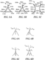
- angle is defined hereinbelow, for example, in reference to FIGS. 6A-6D .
- calcining refers to removal volatile matter (e.g., free water) from a ceramic precursor by heating at lower temperature conditions than typically used for sintering.
- ceramic abrasive particle refers to an abrasive particle comprising ceramic material.
- corner refers to the place, position, or angle formed by the meeting of two converging lines or edges.
- a corner may be sharp as, e.g., a point or edge.
- a corner may also be a generally rounded region connecting adjacent lines or faces. In the present invention two corners of the first region of the perimeter are sharp.
- draft angle refers to an angle of taper, incorporated into a wall of a mold cavity so that the opening of the mold cavity is wider than its base.
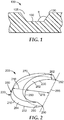
- FIG. 1 which shows a cross-section of mold 100 and mold cavity 105
- draft angle ⁇ is the angle between mold base 150 and mold wall 130.
- the draft angle can be varied to change the relative sizes of the first and second surfaces and the sides of the peripheral surface.
- the draft angle ⁇ can be 90 degrees or in a range of from about 95 degrees to about 130 degrees, from about 95 degrees to about 125 degrees, from about 95 degrees to about 120 degrees, from about 95 degrees to about 115 degrees, from about 95 degrees to about 110 degrees, from about 95 degrees to about 105 degrees, or from about 95 degrees to about 100 degrees.
- the term draft angle also refers to the angle of taper of walls of a molded body corresponding to the draft angle of the mold used to produce it.
- a draft angle of the exemplary shaped ceramic abrasive particle 300 in FIG. 3 would be the angle between second surface 370 and wall 384.
- face refers to a substantially planar surface, which may comprise minor imperfections, for example, as arising during manufacture.
- interior angle refers to an angle, within the perimeter, defined by two adjacent edges of the perimeter.
- length refers to the maximum extent of an object along its greatest dimension.
- major surface refers to a surface that is larger than at least half of the surfaces in the object being referenced.
- peripheral refers to a closed boundary of a surface, which may be a planar surface, or a non-planar surface.
- predetermined shape means that the shape is replicated from a mold cavity used during making of the ceramic abrasive particle.
- predetermined shape excludes random shapes obtained by a mechanical crushing operation.
- the term "sintering” refers a process in which heating of a ceramic precursor material causes it to undergo substantial transformation to a corresponding ceramic material.
- thickness refers to the maximum extent of something along a dimension orthogonal to both the length and the width.
- width refers to the maximum extent of something along a dimension orthogonal to the length.
- exemplary shaped ceramic abrasive particle 200 comprises first surface 210 having perimeter 220. Second surface 270 is opposite, and does not contact first surface 210. Peripheral surface 280 has a predetermined shape, and is disposed between and connects first and second major surfaces 210, 270. Perimeter 220 comprises first and second edges 230, 232. Peripheral surface 280 comprises first and second walls 282, 284. First and second edges 230, 232 respectively represent the intersection of first and second walls 282, 284 with perimeter 220. First region 290 of perimeter 220 comprises first edge 230 and extends inwardly and terminates at first and second corners 250, 252 defining respective acute interior angles 260, 262.
- an inwardly extending region of a shaped ceramic abrasive particle according to the present disclosure may have a maximum depth that is at least 5, 10, 15, 20, 25, 30, 35, 40, 45, 50, 55, or even 60 percent of the maximum dimension of the shaped ceramic abrasive particle parallel to the maximum depth.
- a maximum depth that is at least 5, 10, 15, 20, 25, 30, 35, 40, 45, 50, 55, or even 60 percent of the maximum dimension of the shaped ceramic abrasive particle parallel to the maximum depth.
- FIG. 2 shows maximum dimension 218 parallel to maximum depth 215.
- maximum dimension 318 is parallel to maximum depth 315.
- first surface 210 has a first predetermined shape that corresponds to the base of a mold cavity used to form it. However, if a mold having two opposed openings is used (e.g., as in the case of a perforated plate), neither of the first or second major surfaces may have a predetermined shape, while the peripheral surface will.
- shaped ceramic abrasive particles according to the present disclosure have a peripheral surface that includes at least three walls.
- exemplary shaped ceramic abrasive particle 300 comprises first surface 310 having perimeter 320.
- Perimeter 320 comprises first, second, and third edges 330, 332, 334.
- First edge 330 is a concave monotonic curve, while second and third edges 332, 334 are substantially straight edges.
- Second surface 370 is opposite, and does not contact, first major surface 310.
- Peripheral surface 380 has a predetermined shape, and is disposed between and connects first and second surfaces 310, 370.
- Peripheral surface 380 comprises first, second, and third walls 382, 384, 386.
- First, second, and third edges 330, 332, 334 respectively represent the intersection of first, second, and third walls 382, 384, 386 with perimeter 320.
- First region 390 of perimeter 320 comprises inwardly extending first edge 330, and terminates at first and second corners 350, 352 defining respective first and second acute interior angles 360, 362.
- the first region of the perimeter may comprise a single curved inwardly extending edge, however it is also contemplated that the first region of the perimeter may comprise multiple edges (e.g., 2, 3, 4, 5, 6, 7, 8, 9, 10 edges, or more).
- exemplary shaped ceramic abrasive particle 400 comprises first surface 410 having perimeter 420.
- Perimeter 420 comprises first, second, third, and fourth substantially straight edges 430, 432, 434, 436.
- Second surface 470 is opposite, and does not contact, first surface 410.
- Peripheral surface 480 comprises first, second, third, and fourth walls 482, 484, 486, 488.
- Peripheral surface 480 has a predetermined shape, and is disposed between and connects first and second major surfaces 410, 470.
- First, second, third, and fourth edges 430, 432, 434, 436 respectively represent the intersection of first, second, third, and fourth walls 482, 484, 486, and 488 with perimeter 420.
- First region 490 of perimeter 420 comprises first edge 430 and fourth edge 436, and extends inwardly. First region 490 terminates at first and second corners 450, 452 defining respective first and second acute interior angles 460, 462.
- FIGS. 3 and 4 depict shaped ceramic abrasive particles that have perimeters that are arrowhead-shaped. Likewise, in some embodiments, the shaped ceramic abrasive particles themselves may be arrowhead shaped.
- exemplary shaped ceramic abrasive particle 500a has perimeter 520a of first surface 510a with two inwardly extending regions 590a, 592a formed by edges 530a, 532a and each terminating at two of acute corners 550a, 552a, 554a.
- FIG. 5A exemplary shaped ceramic abrasive particle 500a has perimeter 520a of first surface 510a with two inwardly extending regions 590a, 592a formed by edges 530a, 532a and each terminating at two of acute corners 550a, 552a, 554a.
- exemplary shaped ceramic abrasive particle 500b has perimeter 520b of first surface 510b with three inwardly extending regions 590b, 592b, 594b formed by edges 530b, 532b, 534b and each terminating at two of acute corners 550b, 552b, 554b.
- exemplary shaped ceramic abrasive particle 500c of first surface 510c has perimeter 520c with four inwardly extending regions 590c, 592c, 594c, 596c formed by edges 530c, 532c, 534c, 536c at each terminating at two corners 550c, 552c, 554c, 556c defining acute interior angles (not shown).
- the perimeter of the first major surface extends outwardly.
- the perimeter may be outwardly extending except for one, two, three, or four inwardly extending regions.
- Inwardly extending region(s) of the perimeter may comprise, for example, single curved edge(s) (e.g., monotonic curved edge(s)), or multiple curved or substantially straight (e.g., linear) edges, or a combination of curved and substantially straight edges.
- shaped ceramic abrasive particles according to the present disclosure have thicknesses that are substantially less than their length and/or width, although this is not a requirement.
- the thickness of shaped ceramic abrasive particle may be less than or equal to one-third, one-fifth, or one-tenth of its length and/or width.
- first and second surfaces are substantially parallel, or even parallel; however, this is not a requirement. For example, random deviations due to drying may result in one or both of the first and second major surfaces being non planar.
- first and/or second major surface may have parallel grooves formed therein, for example, as described in U.S. Pat. Appln. Publ. No. 2010/0146867 A1 (Boden et al. ).
- Shaped ceramic abrasive particles according to the present disclosure comprise ceramic material. In some embodiments, they may consist essentially of ceramic material or even consist of ceramic material, although they may contain non-ceramic phases (e.g., as in a glass-ceramic). Examples of suitable ceramic materials include alpha alumina, fused alumina-zirconia, and fused oxynitrides. Further details concerning sol-gel derived ceramic materials suitable for use in shaped ceramic abrasive particles according to the present disclosure can be found in, for example, U.S. Pat. No. 4,314,827 (Leitheiser et al. ); U.S. Pat. No. 4,518,397 (Leitheiser et al. ); U.S. Pat. No.
- shaped ceramic abrasive particles according to the present disclosure may be tapered corresponding a draft angle of the mold, for example, as described in U.S. Pat. Appln. Publ. No. 2010/0151196 A1 (Adefris et al. ).
- the peripheral surface may not taper (i.e., it may be vertical), and/or the first and second surfaces may have the same size and shape.
- interior angles formed between the inwardly extending region and either or both adjacent edges of the perimeter are smaller than would be the case if the inwardly extending region was replaced, for example, by a single straight line segment or a convex edge.
- the interior angles of the two corners adjacent to the inwardly extending region may be substantially reduced.
- the interior angles may be in a range of from 5, 10, 15, 20, 25, or 30 degrees up to 35, 40, 45, 50, or 55 degrees, or from 40 to 55 degrees. In some embodiments, the interior angles may be in a range of from 35 to 55 degrees, from 40 to 55 degrees, or even from 45 to 55 degrees, although other values are also possible. Similarly, if two (or three) of the triangle's edges are replaced with inwardly extending curved edges, the interior angles of their adjacent corners may fall in the same range or be even lower. The same trend occurs in the case of perimeters having four or more edges, although the interior angle values may tend to be larger. In the invention, the first acute interior angle is from 35 to 55 degrees and the second acute interior angle is from 35 to 55 degrees.
- tangents T 1 , T 2 In order to measure the interior angle ( ⁇ ) of a corner of the perimeter, one takes the angle formed between the tangents (T 1 , T 2 ) of respective edges forming the corner at their closest point to the corner that has not passed an inflection point with respect to the inwardly extending region.
- tangents T 1a and T 2a In the case of intersecting straight edges (e.g., as shown in FIG. 6A ), tangents T 1a and T 2a have the same slope as the edges themselves and the interior angle can be easily determined.
- one or both or the edges are monotonic inwardly extending curves (e.g., as shown in FIGS.
- the tangents (T 1b and T 2b or T 1c and T 2c ), respectively) can likewise be readily determined by approaching the corner along the curved edge(s).
- the corner is round or otherwise deformed (e.g., as shown in FIG. 6D )
- the measurement of the interior angle of the corner could become more problematic.
- the tangents T 1d and T 2d should be determined by measuring the tangent of each adjacent edge as they approach the inflection points (if present) proximate to the corner, shown as P 1 and P 2 in FIG. 6D .
- Shaped ceramic abrasive particles according to the present disclosure are typically used as a plurality of particles that may include the shaped ceramic abrasive particles of the present disclosure, other shaped abrasive particles, and/or crushed abrasive particles.
- a plurality of abrasive particles according to the present disclosure may comprise, on a numerical basis, at least 10, 20, 30, 40, 50, 60, 70, 80, 90, 95, or even 99 percent, or more percent of shaped ceramic abrasive particles described herein.
- the shaped ceramic abrasive particles may have the same nominal size and shape, although in some embodiments, it may be useful to use a combination of sizes and/or shapes.
- shaped ceramic abrasive particles according to the present disclosure have a relatively small maximum particle dimension; for example, less than about 1 centimeter (cm), 5 millimeters (mm), 2 mm, 1 mm, 200 micrometers, 100 micrometers, 50 micrometers, 20 micrometers, 10 micrometers, or even less than 5 micrometers, although other sizes may be used.
- any of the abrasive particles referred to in the present disclosure may be sized according to an abrasives industry recognized specified nominal grade.
- Exemplary abrasive industry recognized grading standards include those promulgated by ANSI (American National Standards Institute), FEPA (Federation of European Producers of Abrasives), and JIS (Japanese Industrial Standard).
- Such industry accepted grading standards include, for example: ANSI 4, ANSI 6, ANSI 8, ANSI 16, ANSI 24, ANSI 30, ANSI 36, ANSI 40, ANSI 50, ANSI 60, ANSI 80, ANSI 100, ANSI 120, ANSI 150, ANSI 180, ANSI 220, ANSI 240, ANSI 280, ANSI 320, ANSI 360, ANSI 400, and ANSI 600; FEPA P8, FEPA P12, FEPA P16, FEPA P24, FEPA P30, FEPA P36, FEPA P40, FEPA P50, FEPA P60, FEPA P80, FEPA PI00, FEPA P120, FEPA P150, FEPA P180, FEPA P220, FEPA P320, FEPA P400, FEPA P500, FEPA P600, FEPA P800, FEPA P1000, and FEPA P1200; and JIS 8, JIS 12, JIS 16, JIS 24, JIS 36, JIS 46
- abrasives industry recognized specified nominal grade also includes abrasives industry recognized specified nominal screened grades.
- specified nominal screened grades may use U.S.A. Standard Test Sieves conforming to ASTM E-11-09 "Standard Specification for Wire Cloth and Sieves for Testing Purposes.”
- ASTM E-11-09 sets forth requirements for the design and construction of testing sieves using a medium of woven wire cloth mounted in a frame for the classification of materials according to a designated particle size.
- a typical designation may be represented as -18+20, meaning that the shaped ceramic abrasive particles pass through a test sieve meeting ASTM E11-09 "Standard Specification for Woven Wire Test Sieve Cloth and Test Sieves" specifications for the number 18 sieve and are retained on a test sieve meeting ASTM E11-09 specifications for the number 20 sieve.
- the shaped ceramic abrasive particles have a particle size such that at least 90 percent of the particles pass through an 18 mesh test sieve and can be retained on a 20, 25, 30, 35, 40, 45, or 50 mesh test sieve.
- the shaped ceramic abrasive particles can have a nominal screened grade comprising: -18+20, -20/+25, -25+30, -30+35, - 35+40, 5 -40+45, -45+50, -50+60, -60+70, -70/+80, -80+100, -100+120, -120+140, -140+170, -170+200, -200+230, -230+270, -270+325, -325+400, -400+450, -450+500, or -500+635.
- shaped ceramic abrasive particles can be made according to a multistep process.
- the process can be carried out using a ceramic precursor dispersion (e.g., a dispersion (e.g., a sol-gel) comprising a ceramic precursor material).
- a ceramic precursor dispersion e.g., a dispersion (e.g., a sol-gel) comprising a ceramic precursor material.
- the method comprises the steps of making either a seeded or non-seeded ceramic precursor dispersion that can be converted into a corresponding ceramic (e.g., a boehmite sol-gel that can be converted to alpha alumina); filling one or more mold cavities having the desired outer shape of the shaped abrasive particle with a ceramic precursor dispersion, drying the ceramic precursor dispersion to form shaped ceramic precursor particles; removing the shaped ceramic precursor particles from the mold cavities; calcining the shaped ceramic precursor particles to form calcined, shaped ceramic precursor particles, and then sintering the calcined, shaped ceramic precursor particles to form shaped ceramic abrasive particles.
- a seeded or non-seeded ceramic precursor dispersion that can be converted into a corresponding ceramic
- a corresponding ceramic e.g., a boehmite sol-gel that can be converted to alpha alumina
- the calcining step is omitted and the shaped ceramic precursor particles are sintered directly after removal from the mold.
- the mold may be made of a sacrificial material (e.g., a polyolefin material) that is burned off during calcining or sintering, thereby eliminating to separate the ceramic precursor particles from it during processing.
- the first process step involves providing either a seeded or non-seeded dispersion of a ceramic precursor material (i.e., a ceramic precursor dispersion) that can be converted into a ceramic material.
- a ceramic precursor dispersion often comprises a volatile liquid component.
- the volatile liquid component is water.
- the ceramic precursor dispersion should comprise a sufficient amount of liquid for the viscosity of the dispersion to be sufficiently low to enable filling mold cavities and replicating the mold surfaces, but not so much liquid as to cause subsequent removal of the liquid from the mold cavity to be prohibitively expensive.
- the ceramic precursor dispersion comprises from 2 to 90 percent by weight of the particles that can be converted into ceramic, such as particles of aluminum oxide monohydrate (boehmite) or another alumina precursor, and at least 10 to 98 percent by weight, or from 50 to 70 percent by weight, or 50 to 60 percent by weight, of the volatile component such as water.
- the ceramic precursor dispersion in some embodiments contains from 30 to 50 percent, or 40 to 50 percent by weight solids.
- useful ceramic precursor dispersions include zirconium oxide sols, vanadium oxide sols, cerium oxide sols, aluminum oxide sols, and combinations thereof.
- Useful aluminum oxide dispersions include, for example, boehmite dispersions and other aluminum oxide hydrates dispersions. Boehmite can be prepared by known techniques or can be obtained commercially. Examples of commercially available boehmite include products having the trade designations "DISPERAL”, and “DISPAL”, both available from Sasol North America, Inc. or "HIQ-40" available from BASF Corporation. These aluminum oxide monohydrates are relatively pure; that is, they include relatively little, if any, hydrate phases other than monohydrates, and have a high surface area.
- the physical properties of the resulting shaped ceramic abrasive particles will generally depend upon the type of material used in the ceramic precursor dispersion.
- a "gel” is a three dimensional network of solids dispersed in a liquid.
- the ceramic precursor dispersion may contain a modifying additive or precursor of a modifying additive.
- the modifying additive can function to enhance some desirable property of the abrasive particles or increase the effectiveness of the subsequent sintering step.
- Modifying additives or precursors of modifying additives can be in the form of soluble salts, typically water soluble salts.
- They typically consist of a metal-containing compound and can be a precursor of oxide of magnesium, zinc, iron, silicon, cobalt, nickel, zirconium, hafnium, chromium, yttrium, praseodymium, samarium, ytterbium, neodymium, lanthanum, gadolinium, cerium, dysprosium, erbium, titanium, and mixtures thereof.
- concentrations of these additives that can be present in the ceramic precursor dispersion can be varied based on skill in the art.
- the introduction of a modifying additive or precursor of a modifying additive will cause the ceramic precursor dispersion to gel.
- the ceramic precursor dispersion can also be induced to gel by application of heat over a period of time to reduce the liquid content in the dispersion through evaporation.
- the ceramic precursor dispersion can also contain a nucleating agent.
- Nucleating agents suitable for this disclosure can include fine particles of alpha alumina, alpha ferric oxide or its precursor, titanium oxides and titanates, chrome oxides, or any other material that will nucleate the transformation. The amount of nucleating agent, if used, should be sufficient to effect the transformation of alpha alumina. Nucleating alpha alumina precursor dispersions is disclosed in U.S. Patent No. 4,744,802 (Schwabel ).
- a peptizing agent can be added to the ceramic precursor dispersion to produce a more stable hydrosol or colloidal ceramic precursor dispersion.
- Suitable peptizing agents are monoprotic acids or acid compounds such as acetic acid, hydrochloric acid, formic acid, and nitric acid. Multiprotic acids can also be used but they can rapidly gel the ceramic precursor dispersion, making it difficult to handle or to introduce additional components thereto.
- Some commercial sources of boehmite contain an acid titer (such as absorbed formic or nitric acid) that will assist in forming a stable ceramic precursor dispersion.
- the ceramic precursor dispersion can be formed by any suitable means; for example, in the case of a sol-gel alumina precursor by simply mixing aluminum oxide monohydrate with water containing a peptizing agent or by forming an aluminum oxide monohydrate slurry to which the peptizing agent is added.
- Defoamers or other suitable chemicals can be added to reduce the tendency to form bubbles or entrain air while mixing. Additional chemicals such as wetting agents, alcohols, or coupling agents can be added if desired.
- the second process step involves providing a mold having at least one mold cavity, and preferably a plurality of cavities formed in at least one major surface of the mold.
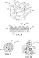
- exemplary mold 700 defines mold cavity 795.
- Mold cavity 795 is laterally bounded by peripheral mold surface 780 comprising first, second, and third mold walls 782, 784, 786.
- Mold cavity 795 has outer opening 797 defined by a perimeter 720.
- First mold wall 782 intersects perimeter 720 at first edge 730.
- Second mold wall 784 intersects perimeter 720 at second edge 732.
- First region 790 of perimeter 720 extends inwardly and comprises first edge 730, which terminates at first and second corners 750, 752, which define respective first and second acute interior angles 760, 762.
- the mold is formed as a production tool, which can be, for example, a belt, a sheet, a continuous web, a coating roll such as a rotogravure roll, a sleeve mounted on a coating roll, or a die.
- the production tool comprises polymeric material.
- suitable polymeric materials include thermoplastics such as polyesters, polycarbonates, poly(ether sulfone), poly(methyl methacrylate), polyurethanes, polyvinylchloride, polyolefin, polystyrene, polypropylene, polyethylene or combinations thereof, or thermosetting materials.
- the entire tooling is made from a polymeric or thermoplastic material.
- the surfaces of the tooling in contact with the ceramic precursor dispersion while drying comprises polymeric or thermoplastic materials and other portions of the tooling can be made from other materials.
- a suitable polymeric coating may be applied to a metal tooling to change its surface tension properties by way of example.
- a polymeric or thermoplastic production tool can be replicated off a metal master tool.
- the master tool will have the inverse pattern desired for the production tool.
- the master tool can be made in the same manner as the production tool.
- the master tool is made out of metal, e.g., nickel and is diamond turned.
- the master tool is at least partially formed using stereolithography.
- the polymeric sheet material can be heated along with the master tool such that the polymeric material is embossed with the master tool pattern by pressing the two together.
- a polymeric or thermoplastic material can also be extruded or cast onto the master tool and then pressed. The thermoplastic material is cooled to solidify and produce the production tool.
- thermoplastic production tool If a thermoplastic production tool is utilized, then care should be taken not to generate excessive heat that may distort the thermoplastic production tool limiting its life. More information concerning the design and fabrication of production tooling or master tools can be found in U.S. Patent Nos. 5,152,917 (Pieper et al. ); 5,435,816 (Spurgeon et al. ); 5,672,097 (Hoopman et al. ); 5,946,991 (Hoopman et al. ); 5,975,987 (Hoopman et al. ); and 6,129,540 (Hoopman et al. ).
- Access to cavities can be from an opening in the top surface or bottom surface of the mold.
- the cavities can extend for the entire thickness of the mold.
- the cavities can extend only for a portion of the thickness of the mold.
- the top surface is substantially parallel to bottom surface of the mold with the cavities having a substantially uniform depth.
- At least one edge of the mold, that is, the edge in which the cavities are formed, can remain exposed to the surrounding atmosphere during the step in which the volatile component is removed.
- the cavities have a specified three-dimensional shape to make the shaped ceramic abrasive particles.
- the depth dimension is equal to the perpendicular distance from the top surface to the lowermost point on the bottom surface.
- the depth of a given cavity can be uniform or can vary along its length and/or width.
- the cavities of a given mold can be of the same shape or of different shapes.
- the third process step involves filling the cavities in the mold with the ceramic precursor dispersion (e.g., by a conventional technique).
- a knife roll coater or vacuum slot die coater can be used.
- a mold release can be used to aid in removing the particles from the mold if desired.
- Typical mold release agents include oils such as peanut oil or mineral oil, fish oil, silicones, polytetrafluoroethylene, zinc stearate, and graphite.
- mold release agent such as peanut oil
- a liquid such as water or alcohol
- mold release agent such as peanut oil
- a liquid such as water or alcohol
- mold release agent such as peanut oil
- a liquid such as water or alcohol
- the ceramic precursor dispersion is applied to the surfaces of the production tooling in contact with the ceramic precursor dispersion such that between about 0.1 mg/in 2 (0.02 mg/cm 2 ) to about 3.0 mg/in 2 (0.5 mg/cm 2 ), or between about 0.1 mg/in 2 (0.02 mg/cm 2 ) to about 5.0 mg/in 2 (0.8 mg/cm 2 ) of the mold release agent is present per unit area of the mold when a mold release is desired.
- the top surface of the mold is coated with the ceramic precursor dispersion. The ceramic precursor dispersion can be pumped onto the top surface.
- a scraper or leveler bar i.e., a screed
- the remaining portion of the ceramic precursor dispersion that does not enter cavity can be removed from top surface of the mold and recycled.
- a small portion of the ceramic precursor dispersion can remain on the top surface and in other embodiments the top surface is substantially free of the dispersion.
- the pressure applied by the scraper or leveler bar is typically less than 100 psi (0.7 MPa), less than 50 psi (0.3 MPa), or even less than 10 psi (69 kPa).
- no exposed surface of the ceramic precursor dispersion extends substantially beyond the top surface.
- the exposed surfaces of the cavities result in substantially planar faces of the shaped ceramic abrasive particles
- it may be desirable to overfill the cavities e.g., using a micronozzle array) and slowly dry the ceramic precursor dispersion.
- the fourth process step involves removing the volatile component to dry the dispersion.
- the volatile component is removed by fast evaporation rates.
- removal of the volatile component by evaporation occurs at temperatures above the boiling point of the volatile component.
- An upper limit to the drying temperature often depends on the material the mold is made from.
- the temperature should be less than the melting point of the plastic.
- the drying temperatures can be between about 90°C to about 165°C, or between about 105°C to about 150°C, or between about 105°C to about 120°C. Higher temperatures can lead to improved production speeds but can also lead to degradation of the polypropylene tooling limiting its useful life as a mold.
- the fifth process step involves removing resultant shaped ceramic precursor particles from the mold cavities.
- the shaped ceramic precursor particles can be removed from the cavities by using the following processes alone or in combination on the mold: gravity, vibration, ultrasonic vibration, vacuum, or pressurized air to remove the particles from the mold cavities.
- the shaped ceramic precursor particles can be further dried outside of the mold. If the ceramic precursor dispersion is dried to the desired level in the mold, this additional drying step is not necessary. However, in some instances it may be economical to employ this additional drying step to minimize the time that the ceramic precursor dispersion resides in the mold. Typically, the shaped ceramic precursor particles will be dried from 10 to 480 minutes, or from 120 to 400 minutes, at a temperature from 50°C to 160°C, or at 120°C to 150°C.
- the sixth process step involves calcining the shaped ceramic precursor particles. During calcining, essentially all the volatile material is removed, and the various components that were present in the ceramic precursor dispersion are transformed into metal oxides.
- the shaped ceramic precursor particles are generally heated to a temperature from 400°C to 800°C, and maintained within this temperature range until the free water and over 90 percent by weight of any bound volatile material are removed.
- a water-soluble salt can be introduced by impregnation into the pores of the calcined, shaped ceramic precursor particles. Then the shaped ceramic precursor particles are pre-fired again. This option is further described in U.S. Patent No. 5,164,348 (Wood ).
- the seventh process step involves sintering the calcined, shaped ceramic precursor particles to form ceramic particles.
- the calcined, shaped ceramic precursor particles Prior to sintering, the calcined, shaped ceramic precursor particles are not completely densified and thus lack the desired hardness to be used as shaped ceramic abrasive particles. Sintering takes place by heating the calcined, shaped ceramic precursor particles to a temperature of from 1000°C to 1650°C. The length of time to which the calcined, shaped ceramic precursor particles must be exposed to the sintering temperature to achieve this level of conversion depends upon various factors but usually from five seconds to 48 hours is typical.
- the duration for the sintering step ranges from one minute to 90 minutes.
- the shaped ceramic abrasive particles can have a Vickers hardness of 10 GPa (gigapascals), 16 GPa, 18 GPa, 20 GPa, or greater.
- Shaped ceramic abrasive particles composed of crystallites of alpha alumina, magnesium alumina spinel, and a rare earth hexagonal aluminate may be prepared using sol-gel alpha alumina precursor particles according to methods described in, for example, U.S. Patent No. 5,213,591 (Celikkaya et al. ) and U.S. Publ. Pat. Appl. Nos. 2009/0165394 A1 (Culler et al. ) and 2009/0169816 A1 (Erickson et al. ).
- Alpha alumina abrasive particles may contain zirconia as disclosed in U.S. Pat. No. 5,551,963 (Larmie ).
- alpha alumina abrasive particles may have a microstructure or additives, for example, as disclosed in U.S. Pat. No. 6,277,161 (Castro ). More information concerning methods to make shaped ceramic abrasive particles is disclosed in co-pending U.S. Publ. Patent Appln. No. 2009/0165394 A1 (Culler et al. ).
- Surface coatings on the shaped ceramic abrasive particles may be used to improve the adhesion between the shaped ceramic abrasive particles and a binder material in abrasive articles, or can be used to aid in electrostatic deposition of the shaped ceramic abrasive particles.
- surface coatings as described in U.S. Patent No. 5,352,254 in an amount of 0.1 to 2 percent surface coating to shaped abrasive particle weight may be used.
- Such surface coatings are described in U.S. Patent Nos. 5,213,591 (Celikkaya et al. ); 5,011,508 (Wald et al.
- the surface coating may prevent the shaped abrasive particle from capping.
- Capping is the term to describe the phenomenon where metal particles from the workpiece being abraded become welded to the tops of the shaped ceramic abrasive particles. Surface coatings to perform the above functions are known to those of skill in the art.
- the shaped ceramic abrasive particles of the present disclosure can typically be made using tools (or molds that are inverse replicas thereof) cut using diamond tooling, which provides higher feature definition than other fabrication alternatives such as, for example, stamping or punching.
- the cavities in the tool surface have smooth faces that meet along sharp edges, although this is not a requirement.
- the resultant shaped ceramic abrasive particles have a respective nominal average shape that corresponds to the shape of cavities in the tool surface; however, variations (e.g., random variations) from the nominal average shape may occur during manufacture, and shaped ceramic abrasive particles exhibiting such variations are included within the definition of shaped ceramic abrasive particles as used herein.
- Shaped ceramic abrasive particles are useful, for example, in the construction of abrasive articles, including for example, agglomerate abrasive grain, coated abrasive articles (for example, conventional make and size coated abrasive articles, slurry coated abrasive articles, and structured abrasive articles), abrasive brushes, nonwoven abrasive articles, and bonded abrasive articles such as grinding wheels, hones and whetstones.
- abrasive articles comprise a plurality of abrasive particles retained in a binder.
- Coated abrasive articles generally include a backing, abrasive particles, and at least one binder to secure the abrasive particles to the backing.
- the backing can be any suitable material, including cloth, polymeric film, fiber, nonwoven webs, paper, combinations thereof, and treated versions thereof.
- Suitable binders include inorganic or organic binders (including thermally curable resins and radiation curable resins).
- the abrasive particles can be present in one layer or in two layers of the coated abrasive article.
- exemplary coated abrasive article 800 has a backing (substrate) 802 and abrasive layer 803.
- Abrasive layer 803 includes shaped ceramic abrasive particles 804 secured to a major surface of backing 802 by make layer 805 and size layer 806. In some instances, a supersize coat (not shown) is used.
- Bonded abrasive articles typically include a shaped mass of abrasive particles held together by an organic, metallic, or vitrified binder.
- Such shaped mass can be, for example, in the form of a wheel, such as a grinding wheel or cutoff wheel.
- the diameter of grinding wheels typically is about 1 cm to over 1 meter; the diameter of cut off wheels about 1 cm to over 80 cm (more typically 3 cm to about 50 cm).
- the cut off wheel thickness is typically about 0.5 mm to about 5 cm, more typically about 0.5 mm to about 2 cm.
- the shaped mass can also be in the form, for example, of a honing stone, segment, mounted point, disc (e.g. double disc grinder) or other conventional bonded abrasive shape.
- Bonded abrasive articles typically comprise about 3-50 percent by volume bond material, about 30-90 percent by volume abrasive particles (or abrasive particle blends), up to 50 percent by volume additives (including grinding aids), and up to 70 percent by volume pores, based on the total volume of the bonded abrasive article.
- FIG. 9 An exemplary grinding wheel is shown in FIG. 9 .
- exemplary grinding wheel 900 is depicted, which includes shaped ceramic abrasive particles 911 according to the present disclosure, molded in a wheel and mounted on hub 912.
- Nonwoven abrasive articles typically include an open porous lofty polymer filament structure having shaped ceramic abrasive particles made according to the present disclosure distributed throughout the structure and adherently bonded therein by an organic binder.
- filaments include polyester fibers, polyamide fibers, and polyaramid fibers.
- An exemplary nonwoven abrasive article is shown in FIG. 10 .
- a schematic depiction, greatly enlarged, of a typical nonwoven abrasive article 1000 comprises lofty open fibrous mat 1050 as a substrate, onto which shaped ceramic abrasive particles made according to the present disclosure 1052 are adhered by binder 1054.
- Useful abrasive brushes include those having a plurality of bristles unitary with a backing (see, e.g., U.S. Pat. No. 5,427,595 (Pihl et al. ), U.S. Pat. No. 5,443,906 (Pihl et al. ), U.S. Pat. No. 5,679,067 (Johnson et al. ), and U.S. Pat. No. 5,903,951 (Ionta et al. )). Desirably, such brushes are made by injection molding a mixture of polymer and abrasive particles.
- Suitable organic binders for making abrasive articles include thermosetting organic polymers.
- suitable thermosetting organic polymers include phenolic resins, urea-formaldehyde resins, melamine-formaldehyde resins, urethane resins, acrylate resins, polyester resins, aminoplast resins having pendant ⁇ , ⁇ -unsaturated carbonyl groups, epoxy resins, acrylated urethane, acrylated epoxies, and combinations thereof.
- the binder and/or abrasive article may also include additives such as fibers, lubricants, wetting agents, thixotropic materials, surfactants, pigments, dyes, antistatic agents (e.g., carbon black, vanadium oxide, or graphite), coupling agents (e.g., silanes, titanates or zircoaluminates), plasticizers, suspending agents.
- additives such as fibers, lubricants, wetting agents, thixotropic materials, surfactants, pigments, dyes, antistatic agents (e.g., carbon black, vanadium oxide, or graphite), coupling agents (e.g., silanes, titanates or zircoaluminates), plasticizers, suspending agents.
- the amounts of these optional additives are selected to provide the desired properties.
- the coupling agents can improve adhesion to the abrasive particles and/or filler.
- the binder chemistry may be thermally cured, radiation cured or combinations thereof. Additional details
- vitreous bonding materials which exhibit an amorphous structure and are typically hard, are well known in the art.
- the vitreous bonding material includes crystalline phases.
- Bonded, vitrified abrasive articles made according to the present disclosure may be in the shape of a wheel (including cut off wheels), honing stone, mounted points or other conventional bonded abrasive shape.
- a vitrified bonded abrasive article made according to the present disclosure is in the form of a grinding wheel.
- vitreous bonding materials examples include: silica, silicates, alumina, soda, calcia, potassia, titania, iron oxide, zinc oxide, lithium oxide, magnesia, boria, aluminum silicate, borosilicate glass, lithium aluminum silicate, combinations thereof.
- vitreous bonding materials can be formed from composition comprising from 10 to 100 percent glass frit, although more typically the composition comprises 20 to 80 percent glass frit, or 30 to 70 percent glass frit. The remaining portion of the vitreous bonding material can be a non-frit material.
- the vitreous bond may be derived from a non-frit containing composition.
- Vitreous bonding materials are typically matured at a temperature(s) in a range of about 700°C to about 1500°C, usually in a range of about 800°C to about 1300°C, sometimes in a range of about 900°C to about 1200°C, or even in a range of about 950°C to about 1100°C.
- the actual temperature at which the bond is matured depends, for example, on the particular bond chemistry.
- vitrified bonding materials include those comprising silica, alumina (desirably, at least 10 percent by weight alumina), and boria (desirably, at least 10 percent by weight boria).
- the vitrified bonding material further comprises alkali metal oxide(s) (e.g., Na 2 O and K 2 O) (in some cases at least 10 percent by weight alkali metal oxide(s)).
- Binder materials may also contain filler materials or grinding aids, typically in the form of a particulate material.
- the particulate materials are inorganic materials.
- useful fillers for this disclosure include: metal carbonates (e.g., calcium carbonate (e.g., chalk, calcite, marl, travertine, marble and limestone), calcium magnesium carbonate, sodium carbonate, magnesium carbonate), silica (e.g., quartz, glass beads, glass bubbles and glass fibers) silicates (e.g., talc, clays, (montmorillonite) feldspar, mica, calcium silicate, calcium metasilicate, sodium aluminosilicate, sodium silicate) metal sulfates (e.g., calcium sulfate, barium sulfate, sodium sulfate, aluminum sodium sulfate, aluminum sulfate), gypsum, vermiculite, wood flour, aluminum trihydrate, carbon black, metal oxides (e.g., calcium oxide
- a grinding aid is a material that has a significant effect on the chemical and physical processes of abrading, which results in improved performance.
- a grinding aid(s) will (a) decrease the friction between the abrasive particles and the workpiece being abraded, (b) prevent the abrasive particles from "capping" (i.e., prevent metal particles from becoming welded to the tops of the abrasive particles), or at least reduce the tendency of abrasive particles to cap, (c) decrease the interface temperature between the abrasive particles and the workpiece, or (d) decreases the grinding forces.
- Grinding aids encompass a wide variety of different materials and can be inorganic or organic based.
- chemical groups of grinding aids include waxes, organic halide compounds, halide salts and metals and their alloys.
- the organic halide compounds will typically break down during abrading and release a halogen acid or a gaseous halide compound.
- examples of such materials include chlorinated waxes like tetrachloronaphthalene, pentachloronaphthalene, and polyvinyl chloride.
- halide salts include sodium chloride, potassium cryolite, sodium cryolite, ammonium cryolite, potassium tetrafluoroborate, sodium tetrafluoroborate, silicon fluorides, potassium chloride, and magnesium chloride.
- metals include, tin, lead, bismuth, cobalt, antimony, cadmium, and iron titanium.
- Other miscellaneous grinding aids include sulfur, organic sulfur compounds, graphite, and metallic sulfides. It is also within the scope of the present disclosure to use a combination of different grinding aids, and in some instances this may produce a synergistic effect.
- Grinding aids can be particularly useful in coated abrasive and bonded abrasive articles.
- grinding aid is typically used in the supersize coat, which is applied over the surface of the abrasive particles. Sometimes, however, the grinding aid is added to the size coat.
- the amount of grinding aid incorporated into coated abrasive articles are about 50-300 g/m 2 (desirably, about 80-160 g/m 2 ).
- In vitrified bonded abrasive articles grinding aid is typically impregnated into the pores of the article.
- the abrasive articles can contain 100 percent shaped ceramic abrasive particles made according to the present disclosure, or blends of such abrasive particles with other abrasive particles and/or diluent particles. However, at least about 2 percent by weight, desirably at least about 5 percent by weight, and more desirably about 30-100 percent by weight, of the abrasive particles in the abrasive articles should be shaped ceramic abrasive particles made according to the present disclosure.
- the abrasive particles made according to the present disclosure may be blended with other abrasive particles and/or diluent particles at a ratio between 5 to 75 percent by weight, about 25 to 75 percent by weight about 40 to 60 percent by weight, or about 50 to 55 percent by weight (i.e., in equal amounts by weight).
- suitable conventional abrasive particles include fused aluminum oxide (including white fused alumina, heat-treated aluminum oxide and brown aluminum oxide), silicon carbide, boron carbide, titanium carbide, diamond, cubic boron nitride, garnet, fused alumina-zirconia, and sol-gel-derived abrasive particles.
- blends of abrasive particles may result in an abrasive article that exhibits improved grinding performance in comparison with abrasive articles comprising 100 percent of either type of abrasive particle.
- Suitable diluent particles include marble, gypsum, flint, silica, iron oxide, aluminum silicate, glass (including glass bubbles and glass beads), alumina bubbles, alumina beads and diluent agglomerates.
- the abrasive particles may be uniformly distributed in the abrasive article or concentrated in selected areas or portions of the abrasive article.
- a coated abrasive there may be two layers of abrasive particles.
- the first layer comprises abrasive particles other than shaped ceramic abrasive particles made according to the present disclosure
- the second (outermost) layer comprises shaped ceramic abrasive particles made according to the present disclosure.
- a bonded abrasive there may be two distinct sections of the grinding wheel.
- the outermost section may comprise abrasive particles made according to the present disclosure, whereas the innermost section does not.
- shaped ceramic abrasive particles made according to the present disclosure may be uniformly distributed throughout the bonded abrasive article.
- coated abrasive articles can be found, for example, in U.S. Pat. No. 4,734,104 (Broberg ), U.S. Pat. No. 4,737,163 (Larkey ), U.S. Pat. No. 5,203,884 (Buchanan et al. ), U.S. Pat. No. 5,152,917 (Pieper et al. ), U.S. Pat. No. 5,378,251 (Culler et al. ), U.S. Pat. No. 5,417,726 (Stout et al. ), U.S. Pat. No. 5,436,063 (Follett et al. ), U.S. Pat. No.
- the present disclosure provides a method of abrading a surface, the method comprising contacting at least one shaped ceramic abrasive particle made according to the present disclosure, with a surface of a workpiece; and moving at least of one the shaped ceramic abrasive particles or the contacted surface to abrade at least a portion of said surface with the abrasive particle.
- Methods for abrading with shaped ceramic abrasive particles made according to the present disclosure range from snagging (i.e., high pressure high stock removal) to polishing (e.g., polishing medical implants with coated abrasive belts), wherein the latter is typically done with finer grades (e.g., ANSI 220 and finer) of abrasive particles.
- the shaped ceramic abrasive particles may also be used in precision abrading applications, such as grinding cam shafts with vitrified bonded wheels. The size of the abrasive particles used for a particular abrading application will be apparent to those skilled in the art
- Abrading with shaped ceramic abrasive particles made according to the present disclosure may be done dry or wet.
- the liquid may be introduced supplied in the form of a light mist to complete flood.
- Examples of commonly used liquids include: water, water-soluble oil, organic lubricant, and emulsions.
- the liquid may serve to reduce the heat associated with abrading and/or act as a lubricant.
- the liquid may contain minor amounts of additives such as bactericide, antifoaming agents.
- Shaped ceramic abrasive particles made according to the present disclosure may be useful, for example, to abrade workpieces such as aluminum metal, carbon steels, mild steels, tool steels, stainless steel, hardened steel, titanium, glass, ceramics, wood, wood-like materials (e.g., plywood and particle board), paint, painted surfaces, organic coated surfaces and the like.
- the applied force during abrading typically ranges from about 1 to about 100 kilograms.
- boehmite sol-gel was made using the following recipe: aluminum oxide monohydrate powder (1600 parts) available as DISPERAL from Sasol North America, Inc. was dispersed by high shear mixing in a solution containing water (2400 parts) and 70 aqueous nitric acid (72 parts) for 11 minutes. The resulting sol-gel was aged for at least 1 hour before coating. The sol-gel was forced into production tooling having shaped mold cavities of dimensions reported in Table 1 (below), wherein "NA” means not applicable.
- SAPA shaped alumina particles were prepared according to the disclosure of paragraph [0128] of U.S. Pat. Appln. Publ. No. 2010/0146867 (Boden et al.
- Shaped Ceramic Abrasive Particles of the same general shape and composition as SAPB were prepared according to the disclosure of U.S. Pat. No. 8,142,531 (Adefris et al. ) TABLE 1 SHAPED CERAMIC ABRASIVE PARTICLE SHAPE, REPRESENT - ATIVE FIGURE MAXIMUM STRAIGHT EDGE LENGTH, mm NUMBER OF INWARDLY EXTENDING EDGES INTERSECTION ANGLE WITH INWARDLY EXTENDING EDGE, degrees DRAFT ANGLE ON ALL EDGES, degrees PARTICLE MEDIAN THICKNESS, mm SAP1 triangular, FIG.
- FIG. 11 2.8 1 30 8 0.71 SAP2 triangular, FIG. 15 3.8 1 45 8 0.71 SAP3 triangular, FIG. 16 2.8 1 25 8 0.71 SAP4 square, FIG. 20B 2.8 4 60 8 0.71 SAP5 triangular, smaller scale version of SAP 1 1.3 1 30 8 0.33 SAPA triangular, FIG. 12 using a draft angle of 98 degrees 2.8 0 NA 8 0.71 SAPB square, FIG. 20A 2.8 0 NA 8 0.71 SAPC triangular smaller scale version of SAPA 1.3 0 NA 8 0.33
- a mold release agent 1 percent peanut oil in methanol, was used with about 0.5 mg/in 2 (0.08 mg/cm 2 ) of peanut oil applied to the production tooling having an array of mold cavities.
- the excess methanol was removed by placing sheets of the production tooling in an air convection oven for 5 minutes at 45°C.
- the sol-gel was forced into the cavities with a putty knife so that the openings of the production tooling were completely filled.
- the sol-gel coated production tooling was placed in an air convection oven at 45°C for at least 45 minutes to dry.
- the shaped ceramic precursor particles were removed from the production tooling by passing it over an ultrasonic horn.
- the shaped ceramic precursor particles were calcined at approximately 650°C and then saturated with a with a mixed nitrate solution of MgO, Y 2 O 3 , CoO, and La 2 O 3 .
- All of the shaped ceramic abrasive particles described in the Examples were treated to enhance electrostatic application of the shaped ceramic abrasive particles in a manner similar to the method used to make crushed abrasive particles disclosed in U.S. Patent No. 5,352,254 (Celikkaya ).
- the calcined, precursor shaped ceramic abrasive particles were impregnated with a rare earth oxide (REO) solution comprising 1.4 percent MgO, 1.7 percent Y 2 O 3 , 5.7 percent La 2 O 3 and 0.07 percent CoO.
- REO rare earth oxide
- HYDRAL COAT 5 0.5 micrometer particle size aluminum trihydroxide powder available from Almatis of Leetsdale, Pennsylvania, was dispersed by stirring it in an open beaker. About 100 grams of calcined, precursor shaped ceramic abrasive particles was then impregnated with the 71.4 grams of the HYDRAL COAT 5 powder dispersion in REO solution. The impregnated, calcined, precursor shaped ceramic abrasive particles were allowed to dry after which the particles were again calcined at 650°C and sintered at approximately 1400°C to final hardness. Both the calcining and sintering were carried out using rotary tube kilns under ambient atmosphere.
- the resulting composition was an alumina composition containing 1 weight percent MgO, 1.2 weight percent of Y 2 O 3 , 4 weight percent of La 2 O 3 and 0.05 weight percent of CoO, with traces of TiO 2 , SiO 2 , and CaO.
- Abrasive articles were prepared from the abrasive particles prepared as described above and the coating compositions shown in Table 2.
- 7-inch (17.8 cm) diameter fiber discs with 7/8-inch (2.2-cm) diameter arbor holes of a vulcanized fiber backing having a thickness of 0.83 mm (33 mils) obtained as DYNOS VULCANIZED FIBRE from DYNOS Gmbh, Troisdorf, Germany
- DYNOS VULCANIZED FIBRE obtained as DYNOS VULCANIZED FIBRE from DYNOS Gmbh, Troisdorf, Germany
- the abrasive discs were tested using the following procedure. Abrasive discs (7-inch (17.8 cm) diameter) for evaluation were attached to a rotary grinder fitted with a 7-inch (17.8 cm) ribbed disc pad face plate 80514 EXTRA HARD RED, obtained from 3M Company, St. Paul, Minnesota). The grinder was then activated and urged against an end face of a 0.75 x 0.75 in (1.9 x 1.9 cm) preweighed 1045 carbon steel (or alternatively, 304 stainless steel) bar under a load of 12 lb (4.5 kg). The rotational speed of the disc pad face plate under the above load condition against the workpiece was maintained at 5000 rpm.
- the workpiece was abraded under these conditions for a total of fifty (50) 10-second grinding intervals (cycles). Following each 10-second cycle, the workpiece was allowed to cool to room temperature and weighed to determine the cut of the abrasive operation. Test results were reported as cut rate, incremental cut, and/or cumulated cut vs. number of cycles.
- Example 1 and Comparative Examples A and B demonstrate the effect of abrasive articles comprising the particles of the present disclosure when compared to abrasive articles comprising previously-known abrasive particles.
- Example 1 was prepared according to the general procedure for preparing abrasive discs using SAP1 abrasive particles.
- Comparative Example A was a 7-inch (17.8-cm) diameter fiber disc with a 7/8 inch (2.2 cm) hole made with SAPA and is commercially available as "CUBITRON II FIBER DISC 982C, 36+" from 3M, Saint Paul, Minnesota.
- Comparative Example B was a 7-inch (17.8-cm) diameter fiber disc with a 7/8 inch (2.2 cm) hole made with conventionally crushed 3M Ceramic Abrasive Grain and is commercially available as "988C” from 3M, Saint Paul, Minnesota.
- Example 1 and Comparative Examples A and B were tested according to the Abrasion Test.
- the comparative cut rate and cumulative cut data are shown in FIGS. 13 and 14 , wherein the coated abrasive of Example 1 exhibited cut that was at least 60 percent better than Comparative Example A (a comparable shaped ceramic abrasive particle with straight edges), and more than twice as good as comparable the crushed ceramic grain of Comparative Example B.
- Examples 2 - 6 were prepared to compare with Example 1 to demonstrate the effects of changing the intersecting angle created by an inwardly extending edge with another edge.
- Example 2 was prepared identically to Example 1 with the exception that the abrasive particles were SAP2 instead of SAP1.
- Example 3 was prepared identically to Example 1 with the exception that the abrasive particles were SAP3 instead of SAP1.
- Example 4 was prepared identically to Example 1 with the exception that a supersize coating was applied.
- Example 5 was prepared identically to Example 2 with the exception that a supersize coating was applied.
- Example 6 was prepared identically to Example 3 with the exception that a supersize coating was applied.
- Comparative Example C was prepared identically to Example 1, with the exception that the abrasive particles were SAPA instead of SAP1.
- Comparative Example D was prepared identically to Comparative Example C, with the exception that a supersize coating was applied.
- FIG. 17 shows the comparison of the performance of discs made with particles from Example 1, Example 2, Example 3, and Comparative Example C on 1045 Carbon Steel.
- the initial cut rates of all the discs made with particles having and inwardly extending (concave) wall were higher than those discs made with particles with straight edges.
- the disc of Example 2 performed the best. It maintained a higher cut rate throughout the test.
- FIG. 18 shows the comparison of the performance of discs of Example 4, Example 5, Example 6, and Comparative Example D when used to abrade 304 Stainless Steel.
- the initial cut rates of all the discs made with particles that were supplied with concavities were higher than those discs made with conventional particles.
- Particularly the Example 6 disc made with SAP3 particles performed the best. It maintained higher cut rate than Comparative Example D as well as the other Example discs throughout the test. This higher performance can be demonstrated better as cumulative cut as a function of number of cycles as shown in FIG. 19 .
- Example 7 and Comparative Example E are abrasive articles that demonstrate the effects of an alternative embodiment of the inventive particle when compared to similar particles having straight edges, and also with conventional crushed ceramic abrasive grain and is commercially available as 321 3M Ceramic Abrasive Grain 321 from 3M, Saint Paul, Minnesota.
- Example 7 was made identically to Example 1 with the exception that SAP4 was substituted for SAP 1.
- Comparative Example E was made identically to Example 1 with the exception that SAPB was substituted for SAP1.
- Comparative Example F was made identically to Example 1 with the exception that "3M Ceramic Abrasive Grain 321" (3M, Saint Paul, Minnesota) was substituted for SAP1.
- Example 7 and Comparative Examples E and F were tested according to the Abrasion Test on 1045 carbon steel.
- the test results are shown in FIG. 21 , again show that including an inwardly extending (e.g., concave) region in shaped ceramic abrasive particles transforms poorer-performing shaped particles into better-performing particles when compared to conventionally-crushed particles in abrasive disc articles.
- Examples 8 and Comparative Example G demonstrate the effect of abrasive articles comprising yet another embodiment of the particles of the present disclosure when compared to abrasive articles comprising previously-known abrasive particles.
- Example 8 was prepared according to the general procedure for preparing abrasive discs using SAP5 abrasive particles. Comparative Example G was prepared identically to Example 1 with the exception that the abrasive particles were SAPC instead of SAP1 and the discs were coated with 2.5 grams/disc of the make coat composition, electrostatically coated with 5.5 grams/disc of abrasive particles, and then 6.0 grams/disc of the size coat and 6.0 grams of the supersize coat composition was applied.
- Example 8 and Comparative Example G were tested according to the Abrasion Test on 1045 carbon steel and 304 stainless steel.
- the comparative cut rate data are shown in FIG. 22 for carbon steel and FIG. 23 for stainless steel.
Claims (20)
- Particule abrasive profilée céramique comprenant :une première surface présentant un périmètre comprenant au moins des premier et deuxième bords, dans laquelle une première région du périmètre comprend le deuxième bord et s'étend vers l'intérieur et se termine en deux coins aigus définissant des premier et deuxième angles intérieurs aigus, et dans laquelle le périmètre présente au plus quatre coins qui définissent des angles intérieurs aigus, dans laquelle le premier angle intérieur aigu est compris entre 35 et 55 degrés, et dans lequel le deuxième angle intérieur aigu est compris entre 35 et 55 degrés ;une deuxième surface opposée à la première surface, et non en contact avec celle-ci ; etune surface périphérique disposée entre et reliant les première et deuxième surfaces, dans laquelle la surface périphérique comprend une première paroi qui entre en contact avec le périmètre au niveau du premier bord, dans laquelle la surface périphérique comprend une deuxième paroi qui entre en contact avec le périmètre au niveau du deuxième bord, et dans laquelle la surface périphérique a une première forme prédéterminée, où la particule abrasive profilée céramique comprend une alumine alpha, une alumine-zircone fusionnée et des oxynitrures fusionnés ou dans laquelle la particule abrasive profilée céramique peut être obtenue à partir d'un matériau précurseur de céramique qui est sélectionné parmi un sol d'oxyde de zirconium, un sol d'oxyde de vanadium, un sol d'oxyde de cérium, un sol d'oxyde d'aluminium, et leurs combinaisons, etdans laquelle la surface périphérique est inclinée vers l'intérieur de la première surface vers la deuxième surface.
- Particule abrasive profilée céramique selon la revendication 1, dans laquelle le premier angle intérieur aigu est compris dans une plage entre de 40 et 55 degrés, inclus.
- Particule abrasive profilée céramique selon la revendication 1 ou 2, dans laquelle la particule abrasive profilée céramique a une épaisseur qui est inférieure ou égale à un tiers de sa largeur.
- Particule abrasive profilée céramique selon l'une quelconque des revendications 1 à 3, dans laquelle les particules abrasives profilées céramiques comprennent essentiellement un matériau céramique.
- Particule abrasive profilée céramique selon l'une quelconque des revendications 1 à 4, dans laquelle le matériau céramique comprend de l'alumine alpha.
- Particule abrasive profilée céramique selon l'une quelconque des revendications 1 à 5, dans laquelle les première et deuxième parois s'inclinent vers l'intérieur.
- Pluralité de particules abrasives, dans laquelle la pluralité de particules abrasives comprend, sur une base numérique, au moins 10 pour cent de particules abrasives profilées céramiques selon l'une quelconque des revendications 1 à 6.
- Article abrasif comprenant la pluralité de particules abrasives selon la revendication 7 retenues dans un liant.
- Article abrasif selon la revendication 8, dans lequel l'article abrasif comprend un article abrasif lié.
- Article abrasif selon la revendication 9, dans lequel l'article abrasif lié comprend une meule à abrasif lié.
- Article abrasif selon la revendication 8, dans lequel l'article abrasif comprend un article abrasif revêtu, l'article abrasif revêtu comprenant la pluralité de particules abrasives fixées à un support ayant des troisième et quatrième surfaces principales opposées.
- Article abrasif selon la revendication 8, dans lequel l'article abrasif comprend un article abrasif non-tissé, dans lequel l'article abrasif non-tissé comprend la pluralité de particules abrasives fixées à un voile de fibres non-tissées ouvertes floche.
- Procédé de fabrication de particules abrasives profilées céramiques, le procédé comprenant les étapes consistant à :a) fournir un moule définissant une cavité de moule, dans lequel la cavité de moule possède une ouverture externe définie par un périmètre, dans lequel le périmètre comprend au moins des premier et deuxième bords, dans lequel une première région du périmètre comprend un deuxième bord et s'étend vers l'intérieur et se termine au niveau de deux coins aigus définissant des premier et deuxième angles intérieurs aigus, dans lequel le premier angle intérieur aigu est compris entre 35 et 55 degrés, dans lequel le deuxième angle intérieur aigu est compris entre 35 et 55 degrés, et dans lequel le périmètre présente au plus quatre coins qui définissent des angles intérieurs aigus, et dans lequel la cavité de moule est latéralement liée par une surface de moule périphérique comprenant une première paroi de moule qui coupe le périmètre au niveau d'un premier bord et une deuxième paroi de moule qui coupe le périmètre au niveau du deuxième bord, dans lequel la surface périphérique s'incline vers l'intérieur de la première surface vers la deuxième surface ;b) disposer un matériau précurseur de céramique à l'intérieur de la cavité de moule ;c) convertir le matériau précurseur de céramique disposé à l'intérieur de la cavité de moule en une particule de précurseur de céramique profilée ; etd) convertir la particule de précurseur de céramique profilée en la particule abrasive profilée céramique.
- Procédé selon la revendication 13, dans lequel le premier coin a un premier angle intérieur aigu avec une valeur comprise dans une plage de 40 à 55 degrés, inclus.
- Procédé selon la revendication 13 ou 14, dans lequel la cavité de moule a une profondeur, et dans lequel les première et deuxième parois s'inclinent vers l'intérieur avec une profondeur croissante.
- Procédé selon l'une quelconque des revendications 13 à 15, dans lequel le procédé comprend en outre la séparation de la particule de précurseur céramique profilée du moule avant l'étape d).
- Procédé selon la revendication 16, dans lequel l'étape d) comprend le frittage de la particule de précurseur de céramique profilée.
- Procédé selon la revendication 16, dans lequel l'étape d) comprend la calcination de la particule de précurseur de céramique profilée pour fournir une particule de précurseur de céramique profilée calcinée, et le frittage de la particule de précurseur de céramique profilée calcinée.
- Procédé selon l'une quelconque des revendications 13 à 18, dans lequel la particule abrasive profilée céramique comprend de l'alumine alpha.
- Procédé selon l'une quelconque des revendications 13 à 18, dans lequel la particule abrasive profilée céramique comprend de l'alumine alpha, de l'alumine-zircone fusionnée et des oxynitrures fusionnés ou dans lequel la particule abrasive profilée céramique peut être obtenue à partir d'un matériau précurseur de céramique qui est choisi parmi un sol d'oxyde de zirconium, un sol d'oxyde de vanadium, un sol d'oxyde de cérium, un sol d'oxyde d'aluminium, et leurs combinaisons.
Applications Claiming Priority (2)
| Application Number | Priority Date | Filing Date | Title |
|---|---|---|---|
| US201261620224P | 2012-04-04 | 2012-04-04 | |
| PCT/US2013/031972 WO2013151745A1 (fr) | 2012-04-04 | 2013-03-15 | Particules abrasives, procédé de fabrication de particules abrasives et articles abrasifs |
Publications (3)
| Publication Number | Publication Date |
|---|---|
| EP2834040A1 EP2834040A1 (fr) | 2015-02-11 |
| EP2834040A4 EP2834040A4 (fr) | 2016-04-13 |
| EP2834040B1 true EP2834040B1 (fr) | 2021-04-21 |
Family
ID=49300926
Family Applications (1)
| Application Number | Title | Priority Date | Filing Date |
|---|---|---|---|
| EP13772568.5A Active EP2834040B1 (fr) | 2012-04-04 | 2013-03-15 | Particules abrasives, procédé de fabrication de particules abrasives et articles abrasifs |
Country Status (10)
| Country | Link |
|---|---|
| US (4) | US9771504B2 (fr) |
| EP (1) | EP2834040B1 (fr) |
| JP (1) | JP6072223B2 (fr) |
| KR (1) | KR102075072B1 (fr) |
| CN (1) | CN104254429B (fr) |
| BR (1) | BR112014024937B1 (fr) |
| CA (1) | CA2869434C (fr) |
| MX (2) | MX350057B (fr) |
| RU (1) | RU2621085C2 (fr) |
| WO (1) | WO2013151745A1 (fr) |
Families Citing this family (79)
| Publication number | Priority date | Publication date | Assignee | Title |
|---|---|---|---|---|
| RU2013135445A (ru) | 2010-12-31 | 2015-02-10 | Сэнт-Гобэн Керамикс Энд Пластикс, Инк. | Абразивное изделие (варианты) и способ его формования |
| CN108262695A (zh) | 2011-06-30 | 2018-07-10 | 圣戈本陶瓷及塑料股份有限公司 | 包括氮化硅磨粒的磨料制品 |
| US8840694B2 (en) | 2011-06-30 | 2014-09-23 | Saint-Gobain Ceramics & Plastics, Inc. | Liquid phase sintered silicon carbide abrasive particles |
| CN103826802B (zh) | 2011-09-26 | 2018-06-12 | 圣戈本陶瓷及塑料股份有限公司 | 包括磨料颗粒材料的磨料制品,使用磨料颗粒材料的涂布磨料及其形成方法 |
| EP2798032A4 (fr) | 2011-12-30 | 2015-12-23 | Saint Gobain Ceramics | Formation de particules abrasives formées |
| EP3851248B1 (fr) | 2011-12-30 | 2024-04-03 | Saint-Gobain Ceramics & Plastics, Inc. | Particules abrasives de forme composite et procédé de formation de celles-ci |
| JP6033886B2 (ja) | 2011-12-30 | 2016-11-30 | サン−ゴバン セラミックス アンド プラスティクス,インコーポレイティド | 成形研磨粒子および同粒子を形成する方法 |
| WO2013106602A1 (fr) | 2012-01-10 | 2013-07-18 | Saint-Gobain Ceramics & Plastics, Inc. | Particules abrasives ayant des formes particulières et procédés de mise en forme de telles particules |
| CA3170246A1 (fr) * | 2012-01-10 | 2013-07-18 | Saint-Gobain Ceramics & Plastics, Inc. | Particules abrasives dotees de formes complexes et leur procede de formation |
| WO2013149209A1 (fr) | 2012-03-30 | 2013-10-03 | Saint-Gobain Abrasives, Inc. | Produits abrasifs ayant des fibres fibrillées |
| JP6219557B2 (ja) | 2012-05-16 | 2017-10-25 | スリーエム イノベイティブ プロパティズ カンパニー | 装飾シート及び構造体 |
| US9200187B2 (en) | 2012-05-23 | 2015-12-01 | Saint-Gobain Ceramics & Plastics, Inc. | Shaped abrasive particles and methods of forming same |
| US10106714B2 (en) | 2012-06-29 | 2018-10-23 | Saint-Gobain Ceramics & Plastics, Inc. | Abrasive particles having particular shapes and methods of forming such particles |
| JP5982580B2 (ja) | 2012-10-15 | 2016-08-31 | サンーゴバン アブレイシブズ,インコーポレイティド | 特定の形状を有する研磨粒子およびこのような粒子の形成方法 |
| EP2938459B1 (fr) | 2012-12-31 | 2021-06-16 | Saint-Gobain Ceramics & Plastics, Inc. | Matières particulaires et leurs procédés de formation |
| CA2907372C (fr) | 2013-03-29 | 2017-12-12 | Saint-Gobain Abrasives, Inc. | Particules abrasives ayant des formes particulieres et procedes de formation de telles particules |
| TW201502263A (zh) | 2013-06-28 | 2015-01-16 | Saint Gobain Ceramics | 包含成形研磨粒子之研磨物品 |
| CN110591645A (zh) | 2013-09-30 | 2019-12-20 | 圣戈本陶瓷及塑料股份有限公司 | 成形磨粒及其形成方法 |
| US9566689B2 (en) | 2013-12-31 | 2017-02-14 | Saint-Gobain Abrasives, Inc. | Abrasive article including shaped abrasive particles |
| US9771507B2 (en) | 2014-01-31 | 2017-09-26 | Saint-Gobain Ceramics & Plastics, Inc. | Shaped abrasive particle including dopant material and method of forming same |
| CN110055032A (zh) | 2014-04-14 | 2019-07-26 | 圣戈本陶瓷及塑料股份有限公司 | 包括成形磨粒的研磨制品 |
| MX2016013465A (es) * | 2014-04-14 | 2017-02-15 | Saint-Gobain Ceram & Plastics Inc | Articulo abrasivo que incluye particulas abrasivas conformadas. |
| CN106163743B (zh) * | 2014-04-21 | 2021-10-08 | 3M创新有限公司 | 磨粒和包含磨粒的磨料制品 |
| WO2015184355A1 (fr) | 2014-05-30 | 2015-12-03 | Saint-Gobain Abrasives, Inc. | Procédé d'utilisation d'un article abrasif comprenant des particules abrasives mises en forme |
| DK3046983T3 (da) * | 2014-06-18 | 2020-06-02 | Klingspor Ag | Flerlags-slibepartikler |
| US9914864B2 (en) | 2014-12-23 | 2018-03-13 | Saint-Gobain Ceramics & Plastics, Inc. | Shaped abrasive particles and method of forming same |
| US9707529B2 (en) | 2014-12-23 | 2017-07-18 | Saint-Gobain Ceramics & Plastics, Inc. | Composite shaped abrasive particles and method of forming same |
| US9676981B2 (en) | 2014-12-24 | 2017-06-13 | Saint-Gobain Ceramics & Plastics, Inc. | Shaped abrasive particle fractions and method of forming same |
| TWI634200B (zh) | 2015-03-31 | 2018-09-01 | 聖高拜磨料有限公司 | 固定磨料物品及其形成方法 |
| US10196551B2 (en) | 2015-03-31 | 2019-02-05 | Saint-Gobain Abrasives, Inc. | Fixed abrasive articles and methods of forming same |
| BR112017022200A2 (pt) * | 2015-04-14 | 2018-07-03 | 3M Innovative Properties Co | artigo abrasivo não tecido e método para fabricação do mesmo |
| CA2988012C (fr) | 2015-06-11 | 2021-06-29 | Saint-Gobain Ceramics & Plastics, Inc. | Article abrasif comprenant des particules abrasives profilees |
| EP3374130A4 (fr) * | 2015-11-13 | 2019-07-10 | 3M Innovative Properties Company | Article abrasif lié et son procédé de réalisation |
| WO2017083249A1 (fr) | 2015-11-13 | 2017-05-18 | 3M Innovative Properties Company | Procédé de triage par forme de particules abrasives broyées |
| CN105837179B (zh) * | 2016-03-24 | 2018-05-25 | 湖州华通研磨制造有限公司 | 一种硅铝陶瓷质研磨石及其制备方法 |
| CN105837184B (zh) * | 2016-03-24 | 2018-10-26 | 湖州华通研磨制造有限公司 | 特重铝镁陶瓷质研磨石 |
| WO2017172470A1 (fr) * | 2016-04-01 | 2017-10-05 | 3M Innovative Properties Company | Particules abrasives de forme allongée, leurs procédés de réalisation, et articles abrasifs les comprenant |
| KR102243356B1 (ko) | 2016-05-10 | 2021-04-23 | 생-고뱅 세라믹스 앤드 플라스틱스, 인코포레이티드 | 연마 입자 및 이의 형성 방법 |
| KR102313436B1 (ko) | 2016-05-10 | 2021-10-19 | 생-고뱅 세라믹스 앤드 플라스틱스, 인코포레이티드 | 연마 입자들 및 그 형성 방법 |
| EP3487664B1 (fr) | 2016-07-20 | 2022-02-16 | 3M Innovative Properties Company | Agglomérat abrasif vitrifié façonné, articles abrasifs et procédé d'abrasion |
| US10988648B2 (en) | 2016-09-21 | 2021-04-27 | 3M Innovative Properties Company | Elongated abrasive particle with enhanced retention features |
| EP4349896A2 (fr) | 2016-09-29 | 2024-04-10 | Saint-Gobain Abrasives, Inc. | Articles abrasifs fixes et procédés pour les former |
| WO2018080703A1 (fr) * | 2016-10-25 | 2018-05-03 | 3M Innovative Properties Company | Particules abrasives magnétisables et articles abrasifs les comprenant |
| EP3532246B1 (fr) | 2016-10-25 | 2022-11-30 | 3M Innovative Properties Company | Agglomérat abrasif vitrifié façonné à particules abrasives façonnées, articles abrasifs et procédés associés |
| CN114393523A (zh) * | 2016-12-22 | 2022-04-26 | 3M创新有限公司 | 用于形成磨料颗粒层的设备以及形成磨料制品的方法 |
| US10759024B2 (en) | 2017-01-31 | 2020-09-01 | Saint-Gobain Ceramics & Plastics, Inc. | Abrasive article including shaped abrasive particles |
| US10563105B2 (en) | 2017-01-31 | 2020-02-18 | Saint-Gobain Ceramics & Plastics, Inc. | Abrasive article including shaped abrasive particles |
| EP3638638A1 (fr) * | 2017-06-13 | 2020-04-22 | 3M Innovative Properties Company | Particules abrasives |
| CN110719946B (zh) | 2017-06-21 | 2022-07-15 | 圣戈本陶瓷及塑料股份有限公司 | 颗粒材料及其形成方法 |
| CN113174235A (zh) | 2017-10-02 | 2021-07-27 | 3M创新有限公司 | 细长磨料颗粒、其制备方法以及包含细长磨料颗粒的磨料制品 |
| US20190284460A1 (en) * | 2018-03-13 | 2019-09-19 | Saint-Gobain Ceramics & Plastics, Inc. | Particulate material and method for forming same |
| US11945076B2 (en) | 2018-07-23 | 2024-04-02 | 3M Innovative Properties Company | Articles including polyester backing and primer layer and related methods |
| CN109127009B (zh) * | 2018-08-31 | 2021-02-02 | 贺州市骏鑫矿产品有限责任公司 | 一种用于粉磨钾钠长石的球磨机 |
| CN109290893A (zh) * | 2018-12-05 | 2019-02-01 | 马鞍山迪斯福工业设计有限公司 | 一种木材专用去毛刺装置 |
| US20220064508A1 (en) * | 2018-12-19 | 2022-03-03 | 3M Innovative Properties Company | Serrated shaped abrasive particles and method for manufacturing thereof |
| KR102608901B1 (ko) * | 2018-12-24 | 2023-12-01 | 삼성전자주식회사 | 웨이퍼 그라인딩 휠 |
| CN109760473B (zh) * | 2019-01-25 | 2021-11-05 | 泰州神舟传动科技有限公司 | 一种防水轮毂 |
| CN114630725A (zh) * | 2019-10-23 | 2022-06-14 | 3M创新有限公司 | 在多条边中的一条边内具有凹形空隙的成形磨料颗粒 |
| KR20220116556A (ko) | 2019-12-27 | 2022-08-23 | 세인트-고바인 세라믹스 앤드 플라스틱스, 인크. | 연마 물품 및 이의 형성 방법 |
| EP4081609A1 (fr) * | 2019-12-27 | 2022-11-02 | Saint-Gobain Ceramics & Plastics Inc. | Articles abrasifs et leurs procédés de formation |
| EP4096867A1 (fr) | 2020-01-31 | 2022-12-07 | 3M Innovative Properties Company | Articles abrasifs revêtus |
| WO2021161129A1 (fr) | 2020-02-10 | 2021-08-19 | 3M Innovative Properties Company | Article abrasif revêtu et procédé de fabrication d'un tel article |
| WO2021245494A1 (fr) | 2020-06-04 | 2021-12-09 | 3M Innovative Properties Company | Particules abrasives façonnées et leurs procédés de fabrication |
| EP4171877A1 (fr) | 2020-06-30 | 2023-05-03 | 3M Innovative Properties Company | Articles abrasifs revêtus et leurs procédés de réalisation et d'utilisation |
| WO2022023879A1 (fr) | 2020-07-28 | 2022-02-03 | 3M Innovative Properties Company | Article abrasif revêtu et procédé de fabrication d'un tel article |
| EP4188645A1 (fr) | 2020-07-30 | 2023-06-07 | 3M Innovative Properties Company | Article abrasif et procédé de fabrication associé |
| EP4192650A1 (fr) | 2020-08-10 | 2023-06-14 | 3M Innovative Properties Company | Système d'abrasion et son procédé d'utilisation |
| US20230286111A1 (en) | 2020-08-10 | 2023-09-14 | 3M Innovative Properties Company | Abrasive articles and method of making the same |
| US20230405766A1 (en) | 2020-10-28 | 2023-12-21 | 3M Innovative Properties Company | Method of making a coated abrasive article and coated abrasive article |
| WO2022162580A1 (fr) | 2021-02-01 | 2022-08-04 | 3M Innovative Properties Company | Procédé de fabrication d'un article abrasif revêtu et article abrasif revêtu |
| WO2022221646A1 (fr) * | 2021-04-16 | 2022-10-20 | 3M Innovative Properties Company | Structures linéaires de particules abrasives alignées |
| WO2022229744A1 (fr) | 2021-04-30 | 2022-11-03 | 3M Innovative Properties Company | Meules tronçonneuses abrasives et leurs procédés de fabrication |
| EP4355530A1 (fr) | 2021-06-15 | 2024-04-24 | 3M Innovative Properties Company | Article abrasif enrobé comprenant une résine thermodurcissable biodégradable et son procédé de fabrication et d'utilisation |
| WO2023084362A1 (fr) | 2021-11-15 | 2023-05-19 | 3M Innovative Properties Company | Articles abrasifs non tissés et leurs procédés de fabrication |
| WO2023100104A1 (fr) | 2021-11-30 | 2023-06-08 | 3M Innovative Properties Company | Articles et systèmes abrasifs |
| WO2023156980A1 (fr) | 2022-02-21 | 2023-08-24 | 3M Innovative Properties Company | Article abrasif non-tissé et ses procédés de fabrication |
| WO2023180880A1 (fr) | 2022-03-21 | 2023-09-28 | 3M Innovative Properties Company | Composition durcissable, article abrasif revêtu la contenant et procédés de fabrication et d'utilisation de celle-ci |
| WO2023180877A1 (fr) | 2022-03-21 | 2023-09-28 | 3M Innovative Properties Company | Composition durcissable, support traité, articles abrasifs revêtus les comprenant et leurs procédés de fabrication et d'utilisation |
| WO2023209518A1 (fr) | 2022-04-26 | 2023-11-02 | 3M Innovative Properties Company | Articles abrasifs, procédés de fabrication et utilisation associés |
Citations (13)
| Publication number | Priority date | Publication date | Assignee | Title |
|---|---|---|---|---|
| US3481723A (en) * | 1965-03-02 | 1969-12-02 | Itt | Abrasive grinding wheel |
| US5496386A (en) | 1993-03-18 | 1996-03-05 | Minnesota Mining And Manufacturing Company | Coated abrasive article having diluent particles and shaped abrasive particles |
| US5984988A (en) | 1992-07-23 | 1999-11-16 | Minnesota Minning & Manufacturing Company | Shaped abrasive particles and method of making same |
| US20100151196A1 (en) | 2008-12-17 | 2010-06-17 | 3M Innovative Properties Company | Shaped abrasive particles with a sloping sidewall |
| WO2010077491A2 (fr) | 2008-12-17 | 2010-07-08 | 3M Innovative Properties Company | Particules abrasives en forme d'assiette comportant une surface creuse |
| US20100319269A1 (en) | 2009-06-22 | 2010-12-23 | Erickson Dwight D | Shaped abrasive particles with low roundness factor |
| WO2011068714A2 (fr) | 2009-12-02 | 2011-06-09 | 3M Innovative Properties Company | Particules abrasives façonnées à effilement double |
| WO2011068724A2 (fr) | 2009-12-02 | 2011-06-09 | 3M Innovative Properties Company | Procédé de fabrication d'un article abrasif revêtu comprenant des particules abrasives mises en forme et produit résultant |
| US20110146509A1 (en) | 2009-12-22 | 2011-06-23 | 3M Innovative Properties Company | Transfer assisted screen printing method of making shaped abrasive particles and the resulting shaped abrasive particles |
| WO2011087739A1 (fr) | 2009-12-22 | 2011-07-21 | The Procter & Gamble Company | Composition liquide de nettoyage et/ou de purification |
| WO2011109188A2 (fr) | 2010-03-03 | 2011-09-09 | 3M Innovative Properties Company | Meule abrasive liée |
| WO2011139562A2 (fr) | 2010-04-27 | 2011-11-10 | 3M Innovative Properties Company | Particules céramiques abrasives conformées, procédés de fabrication associés et articles abrasifs contenant ces particules |
| WO2012092590A2 (fr) | 2010-12-31 | 2012-07-05 | Saint-Gobain Ceramics & Plastics, Inc. | Particules abrasives ayant des formes particulières et procédés de formation de telles particules |
Family Cites Families (140)
| Publication number | Priority date | Publication date | Assignee | Title |
|---|---|---|---|---|
| US35570A (en) | 1862-06-10 | Eufus sibley | ||
| CA743715A (en) | 1966-10-04 | The Carborundum Company | Manufacture of sintered abrasive grain of geometrical shape and controlled grit size | |
| US1910444A (en) | 1931-02-13 | 1933-05-23 | Carborundum Co | Process of making abrasive materials |
| DE1694594C3 (de) | 1960-01-11 | 1975-05-28 | Minnesota Mining And Manufacturing Co., Saint Paul, Minn. (V.St.A.) | Reinigungs- und Polierkörper |
| US3041156A (en) | 1959-07-22 | 1962-06-26 | Norton Co | Phenolic resin bonded grinding wheels |
| US3079243A (en) | 1959-10-19 | 1963-02-26 | Norton Co | Abrasive grain |
| GB986847A (en) | 1962-02-07 | 1965-03-24 | Charles Beck Rosenberg Brunswi | Improvements in or relating to abrasives |
| US3387957A (en) | 1966-04-04 | 1968-06-11 | Carborundum Co | Microcrystalline sintered bauxite abrasive grain |
| US3608050A (en) | 1969-09-12 | 1971-09-21 | Union Carbide Corp | Production of single crystal sapphire by carefully controlled cooling from a melt of alumina |
| US3874856A (en) | 1970-02-09 | 1975-04-01 | Ducommun Inc | Porous composite of abrasive particles in a pyrolytic carbon matrix and the method of making it |
| US3909991A (en) | 1970-09-22 | 1975-10-07 | Norton Co | Process for making sintered abrasive grains |
| US4028453A (en) | 1975-10-20 | 1977-06-07 | Lava Crucible Refractories Company | Process for making refractory shapes |
| US4314827A (en) | 1979-06-29 | 1982-02-09 | Minnesota Mining And Manufacturing Company | Non-fused aluminum oxide-based abrasive mineral |
| US4518397A (en) | 1979-06-29 | 1985-05-21 | Minnesota Mining And Manufacturing Company | Articles containing non-fused aluminum oxide-based abrasive mineral |
| US4588419A (en) | 1980-10-08 | 1986-05-13 | Carborundum Abrasives Company | Resin systems for high energy electron curable resin coated webs |
| US4800685A (en) | 1984-05-31 | 1989-01-31 | Minnesota Mining And Manufacturing Company | Alumina bonded abrasive for cast iron |
| US4543107A (en) | 1984-08-08 | 1985-09-24 | Norton Company | Vitrified bonded grinding wheels containing sintered gel aluminous abrasive grits |
| JPS606356A (ja) | 1983-06-20 | 1985-01-14 | Res Dev Corp Of Japan | 微細短繊維焼結型研摩材 |
| US4623364A (en) | 1984-03-23 | 1986-11-18 | Norton Company | Abrasive material and method for preparing the same |
| CA1266569A (fr) | 1984-05-09 | 1990-03-13 | Minnesota Mining And Manufacturing Company | Abrasif colle a substituts mineraux selectifs |
| CA1266568A (fr) | 1984-05-09 | 1990-03-13 | Minnesota Mining And Manufacturing Company | Abrasif colle a substituts mineraux selectifs |
| CA1254238A (fr) | 1985-04-30 | 1989-05-16 | Alvin P. Gerk | Procede sol-gel pour l'obtention de grains d'abrasif et de produits abrasifs ceramiques durables a base d'alumine |
| US4741743A (en) | 1985-08-19 | 1988-05-03 | Norton Company | Grinding wheel with combination of fused and sintered abrasive grits |
| US4770671A (en) | 1985-12-30 | 1988-09-13 | Minnesota Mining And Manufacturing Company | Abrasive grits formed of ceramic containing oxides of aluminum and yttrium, method of making and using the same and products made therewith |
| US4751138A (en) | 1986-08-11 | 1988-06-14 | Minnesota Mining And Manufacturing Company | Coated abrasive having radiation curable binder |
| US4960441A (en) | 1987-05-11 | 1990-10-02 | Norton Company | Sintered alumina-zirconia ceramic bodies |
| US4881951A (en) | 1987-05-27 | 1989-11-21 | Minnesota Mining And Manufacturing Co. | Abrasive grits formed of ceramic containing oxides of aluminum and rare earth metal, method of making and products made therewith |
| AU604899B2 (en) | 1987-05-27 | 1991-01-03 | Minnesota Mining And Manufacturing Company | Abrasive grits formed of ceramic, impregnation method of making the same and products made therewith |
| US4954462A (en) | 1987-06-05 | 1990-09-04 | Minnesota Mining And Manufacturing Company | Microcrystalline alumina-based ceramic articles |
| US4848041A (en) | 1987-11-23 | 1989-07-18 | Minnesota Mining And Manufacturing Company | Abrasive grains in the shape of platelets |
| CH675250A5 (fr) | 1988-06-17 | 1990-09-14 | Lonza Ag | |
| US4898597A (en) | 1988-08-25 | 1990-02-06 | Norton Company | Frit bonded abrasive wheel |
| US5011508A (en) | 1988-10-14 | 1991-04-30 | Minnesota Mining And Manufacturing Company | Shelling-resistant abrasive grain, a method of making the same, and abrasive products |
| YU32490A (en) | 1989-03-13 | 1991-10-31 | Lonza Ag | Hydrophobic layered grinding particles |
| US5009676A (en) | 1989-04-28 | 1991-04-23 | Norton Company | Sintered sol gel alumina abrasive filaments |
| US5035723A (en) | 1989-04-28 | 1991-07-30 | Norton Company | Bonded abrasive products containing sintered sol gel alumina abrasive filaments |
| US5431967A (en) | 1989-09-05 | 1995-07-11 | Board Of Regents, The University Of Texas System | Selective laser sintering using nanocomposite materials |
| US4997461A (en) | 1989-09-11 | 1991-03-05 | Norton Company | Nitrified bonded sol gel sintered aluminous abrasive bodies |
| US5037453A (en) | 1989-09-13 | 1991-08-06 | Norton Company | Abrasive article |
| US5007943A (en) | 1989-11-03 | 1991-04-16 | Norton Company | Sol-gel process alumina abrasive grain blends in coated abrasive material |
| US5094672A (en) | 1990-01-16 | 1992-03-10 | Cincinnati Milacron Inc. | Vitreous bonded sol-gel abrasive grit article |
| US5049166A (en) | 1990-02-27 | 1991-09-17 | Washington Mills Ceramics Corporation | Light weight abrasive tumbling media and method of making same |
| FI84979C (fi) | 1990-04-06 | 1992-02-25 | Ahlstroem Oy | Filter foer separering av partiklar fraon en het gasstroem. |
| US5085671A (en) | 1990-05-02 | 1992-02-04 | Minnesota Mining And Manufacturing Company | Method of coating alumina particles with refractory material, abrasive particles made by the method and abrasive products containing the same |
| US5118326A (en) | 1990-05-04 | 1992-06-02 | Norton Company | Vitrified bonded grinding wheel with mixtures of sol gel aluminous abrasives and silicon carbide |
| US5139978A (en) | 1990-07-16 | 1992-08-18 | Minnesota Mining And Manufacturing Company | Impregnation method for transformation of transition alumina to a alpha alumina |
| US5090968A (en) | 1991-01-08 | 1992-02-25 | Norton Company | Process for the manufacture of filamentary abrasive particles |
| US5152917B1 (en) | 1991-02-06 | 1998-01-13 | Minnesota Mining & Mfg | Structured abrasive article |
| US5378251A (en) | 1991-02-06 | 1995-01-03 | Minnesota Mining And Manufacturing Company | Abrasive articles and methods of making and using same |
| US5131926A (en) | 1991-03-15 | 1992-07-21 | Norton Company | Vitrified bonded finely milled sol gel aluminous bodies |
| US5203886A (en) | 1991-08-12 | 1993-04-20 | Norton Company | High porosity vitrified bonded grinding wheels |
| US5316812A (en) | 1991-12-20 | 1994-05-31 | Minnesota Mining And Manufacturing Company | Coated abrasive backing |
| BR9206806A (pt) | 1991-12-20 | 1995-10-31 | Minnesota Mining & Mfg | Suporte abrasivo revestido e abrasivo revestido |
| US5282875A (en) | 1992-03-18 | 1994-02-01 | Cincinnati Milacron Inc. | High density sol-gel alumina-based abrasive vitreous bonded grinding wheel |
| TW307801B (fr) | 1992-03-19 | 1997-06-11 | Minnesota Mining & Mfg | |
| US5203884A (en) | 1992-06-04 | 1993-04-20 | Minnesota Mining And Manufacturing Company | Abrasive article having vanadium oxide incorporated therein |
| US5366523A (en) | 1992-07-23 | 1994-11-22 | Minnesota Mining And Manufacturing Company | Abrasive article containing shaped abrasive particles |
| US5304331A (en) | 1992-07-23 | 1994-04-19 | Minnesota Mining And Manufacturing Company | Method and apparatus for extruding bingham plastic-type materials |
| BR9306765A (pt) * | 1992-07-23 | 1998-12-08 | Minnesota Mining & Mfg | Processo para a preparação de uma partícula abrasiva e artigo abrasivo |
| US5201916A (en) * | 1992-07-23 | 1993-04-13 | Minnesota Mining And Manufacturing Company | Shaped abrasive particles and method of making same |
| US5213591A (en) | 1992-07-28 | 1993-05-25 | Ahmet Celikkaya | Abrasive grain, method of making same and abrasive products |
| US5312791A (en) | 1992-08-21 | 1994-05-17 | Saint Gobain/Norton Industrial Ceramics Corp. | Process for the preparation of ceramic flakes, fibers, and grains from ceramic sols |
| WO1994007970A1 (fr) | 1992-09-25 | 1994-04-14 | Minnesota Mining And Manufacturing Company | Procede de fabrication de grains abrasifs contenant de l'oxyde d'aluminium et de l'oxyde cerique |
| EP0662110B1 (fr) | 1992-09-25 | 1999-11-24 | Minnesota Mining And Manufacturing Company | Grains abrasifs contenant de l'oxyde de terres rares |
| JP3560341B2 (ja) | 1992-09-25 | 2004-09-02 | ミネソタ・マイニング・アンド・マニュファクチュアリング・カンパニー | アルミナおよびジルコニアを含む砥粒 |
| US5435816A (en) | 1993-01-14 | 1995-07-25 | Minnesota Mining And Manufacturing Company | Method of making an abrasive article |
| US5436063A (en) | 1993-04-15 | 1995-07-25 | Minnesota Mining And Manufacturing Company | Coated abrasive article incorporating an energy cured hot melt make coat |
| US5441549A (en) | 1993-04-19 | 1995-08-15 | Minnesota Mining And Manufacturing Company | Abrasive articles comprising a grinding aid dispersed in a polymeric blend binder |
| ATE182502T1 (de) | 1993-09-13 | 1999-08-15 | Minnesota Mining & Mfg | Schleifartikel, verfahren zur herstellung desselben, verfahren zur verwendung desselben zum endbearbeiten, und herstellungswerkzeug |
| US5409645A (en) | 1993-12-20 | 1995-04-25 | Saint Gobain/Norton Industrial Ceramics Corp. | Molding shaped articles |
| AU1370595A (en) | 1993-12-28 | 1995-07-17 | Minnesota Mining And Manufacturing Company | Alpha alumina-based abrasive grain having an as sintered outer surface |
| US5443603A (en) | 1994-01-11 | 1995-08-22 | Washington Mills Ceramics Corporation | Light weight ceramic abrasive media |
| EP0739263B1 (fr) * | 1994-01-13 | 1999-04-21 | Minnesota Mining And Manufacturing Company | Article abrasif, son procede de fabrication et machine a abraser |
| AU687598B2 (en) | 1994-09-30 | 1998-02-26 | Minnesota Mining And Manufacturing Company | Coated abrasive article, method for preparing the same, and method of using |
| US6054093A (en) | 1994-10-19 | 2000-04-25 | Saint Gobain-Norton Industrial Ceramics Corporation | Screen printing shaped articles |
| US5725162A (en) | 1995-04-05 | 1998-03-10 | Saint Gobain/Norton Industrial Ceramics Corporation | Firing sol-gel alumina particles |
| US5679067A (en) | 1995-04-28 | 1997-10-21 | Minnesota Mining And Manufacturing Company | Molded abrasive brush |
| US5975987A (en) | 1995-10-05 | 1999-11-02 | 3M Innovative Properties Company | Method and apparatus for knurling a workpiece, method of molding an article with such workpiece, and such molded article |
| WO1997014535A1 (fr) | 1995-10-20 | 1997-04-24 | Minnesota Mining And Manufacturing Company | Article abrasif contenant un orthophosphate metallique inorganique |
| US5903951A (en) | 1995-11-16 | 1999-05-18 | Minnesota Mining And Manufacturing Company | Molded brush segment |
| CN1092095C (zh) | 1996-05-08 | 2002-10-09 | 明尼苏达矿业和制造公司 | 包括抗填充成分的磨料制品 |
| US5738696A (en) | 1996-07-26 | 1998-04-14 | Norton Company | Method for making high permeability grinding wheels |
| US6080215A (en) | 1996-08-12 | 2000-06-27 | 3M Innovative Properties Company | Abrasive article and method of making such article |
| US5776214A (en) | 1996-09-18 | 1998-07-07 | Minnesota Mining And Manufacturing Company | Method for making abrasive grain and abrasive articles |
| US6206942B1 (en) | 1997-01-09 | 2001-03-27 | Minnesota Mining & Manufacturing Company | Method for making abrasive grain using impregnation, and abrasive articles |
| US5893935A (en) | 1997-01-09 | 1999-04-13 | Minnesota Mining And Manufacturing Company | Method for making abrasive grain using impregnation, and abrasive articles |
| US5779743A (en) | 1996-09-18 | 1998-07-14 | Minnesota Mining And Manufacturing Company | Method for making abrasive grain and abrasive articles |
| US5946991A (en) | 1997-09-03 | 1999-09-07 | 3M Innovative Properties Company | Method for knurling a workpiece |
| US5863308A (en) | 1997-10-31 | 1999-01-26 | Norton Company | Low temperature bond for abrasive tools |
| WO1999038817A1 (fr) | 1998-01-28 | 1999-08-05 | Minnesota Mining And Manufacturing Company | Procede permettant de fabriquer un grain abrasif par impregnation et articles abrasifs |
| JP2002503559A (ja) * | 1998-02-19 | 2002-02-05 | ミネソタ マイニング アンド マニュファクチャリング カンパニー | ガラス研削用研磨製品および方法 |
| US6080216A (en) | 1998-04-22 | 2000-06-27 | 3M Innovative Properties Company | Layered alumina-based abrasive grit, abrasive products, and methods |
| US6228134B1 (en) | 1998-04-22 | 2001-05-08 | 3M Innovative Properties Company | Extruded alumina-based abrasive grit, abrasive products, and methods |
| US6019805A (en) | 1998-05-01 | 2000-02-01 | Norton Company | Abrasive filaments in coated abrasives |
| US6053956A (en) | 1998-05-19 | 2000-04-25 | 3M Innovative Properties Company | Method for making abrasive grain using impregnation and abrasive articles |
| FR2797638B1 (fr) | 1999-08-20 | 2001-09-21 | Pem Abrasifs Refractaires | Grains abrasifs pour meules, a capacite d'ancrage amelioree |
| US6277161B1 (en) | 1999-09-28 | 2001-08-21 | 3M Innovative Properties Company | Abrasive grain, abrasive articles, and methods of making and using the same |
| US6596041B2 (en) | 2000-02-02 | 2003-07-22 | 3M Innovative Properties Company | Fused AL2O3-MgO-rare earth oxide eutectic abrasive particles, abrasive articles, and methods of making and using the same |
| JP2003532550A (ja) | 2000-05-09 | 2003-11-05 | スリーエム イノベイティブ プロパティズ カンパニー | セラミック研磨複合体を有する多孔質研磨物品、その製造方法、および使用方法 |
| JP3563017B2 (ja) | 2000-07-19 | 2004-09-08 | ロデール・ニッタ株式会社 | 研磨組成物、研磨組成物の製造方法及びポリシング方法 |
| US6776699B2 (en) | 2000-08-14 | 2004-08-17 | 3M Innovative Properties Company | Abrasive pad for CMP |
| EP1770142A3 (fr) | 2000-10-06 | 2008-05-07 | 3M Innovative Properties Company | Procédé de fabrication de particules agglomérées abrasives |
| US8062098B2 (en) | 2000-11-17 | 2011-11-22 | Duescher Wayne O | High speed flat lapping platen |
| US8256091B2 (en) | 2000-11-17 | 2012-09-04 | Duescher Wayne O | Equal sized spherical beads |
| RU2303621C2 (ru) | 2001-08-02 | 2007-07-27 | 3М Инновейтив Пропертиз Компани | Абразивные частицы и способы их получения и применения |
| GB2396157B (en) | 2001-08-09 | 2005-07-20 | Hitachi Maxell | Non-magnetic particles having a plate shape and method for production thereof,abrasive material,polishing article and abrasive fluid comprising such particles |
| US6833014B2 (en) | 2002-07-26 | 2004-12-21 | 3M Innovative Properties Company | Abrasive product, method of making and using the same, and apparatus for making the same |
| US7811496B2 (en) | 2003-02-05 | 2010-10-12 | 3M Innovative Properties Company | Methods of making ceramic particles |
| US7300479B2 (en) | 2003-09-23 | 2007-11-27 | 3M Innovative Properties Company | Compositions for abrasive articles |
| US20050132655A1 (en) | 2003-12-18 | 2005-06-23 | 3M Innovative Properties Company | Method of making abrasive particles |
| TW200538237A (en) | 2004-04-06 | 2005-12-01 | Kure Norton Co Ltd | Porous vitrified grinding wheel and method for production thereof |
| US7297402B2 (en) | 2004-04-15 | 2007-11-20 | Shell Oil Company | Shaped particle having an asymmetrical cross sectional geometry |
| US7867302B2 (en) | 2005-02-22 | 2011-01-11 | Saint-Gobain Abrasives, Inc. | Rapid tooling system and methods for manufacturing abrasive articles |
| US7524345B2 (en) | 2005-02-22 | 2009-04-28 | Saint-Gobain Abrasives, Inc. | Rapid tooling system and methods for manufacturing abrasive articles |
| US7875091B2 (en) | 2005-02-22 | 2011-01-25 | Saint-Gobain Abrasives, Inc. | Rapid tooling system and methods for manufacturing abrasive articles |
| US20070020457A1 (en) | 2005-07-21 | 2007-01-25 | 3M Innovative Properties Company | Composite particle comprising an abrasive grit |
| US7556558B2 (en) | 2005-09-27 | 2009-07-07 | 3M Innovative Properties Company | Shape controlled abrasive article and method |
| DK2125984T3 (da) | 2007-01-23 | 2012-04-02 | Saint Gobain Abrasives Inc | Coatede slibeprodukter, der indeholder aggregater |
| US20090120009A1 (en) * | 2007-11-08 | 2009-05-14 | Chien-Min Sung | Polycrystalline Grits and Associated Methods |
| US8034137B2 (en) | 2007-12-27 | 2011-10-11 | 3M Innovative Properties Company | Shaped, fractured abrasive particle, abrasive article using same and method of making |
| US8123828B2 (en) * | 2007-12-27 | 2012-02-28 | 3M Innovative Properties Company | Method of making abrasive shards, shaped abrasive particles with an opening, or dish-shaped abrasive particles |
| US8142532B2 (en) | 2008-12-17 | 2012-03-27 | 3M Innovative Properties Company | Shaped abrasive particles with an opening |
| WO2010077509A1 (fr) | 2008-12-17 | 2010-07-08 | 3M Innovative Properties Company | Particules abrasives mises en forme comportant des rainures |
| US8551577B2 (en) | 2010-05-25 | 2013-10-08 | 3M Innovative Properties Company | Layered particle electrostatic deposition process for making a coated abrasive article |
| US8765327B2 (en) | 2010-07-12 | 2014-07-01 | 3M Innovative Properties Company | Fuel cell electrodes with conduction networks |
| DE102010038351B4 (de) | 2010-07-23 | 2020-09-03 | Robert Bosch Gmbh | Verfahren und Vorrichtung zum Betreiben eines hybriden Antriebssystems |
| EP2601014B1 (fr) | 2010-08-04 | 2019-09-25 | 3M Innovative Properties Company | Particules abrasives en forme de plaques entrecroisées |
| US9073179B2 (en) | 2010-11-01 | 2015-07-07 | 3M Innovative Properties Company | Laser method for making shaped ceramic abrasive particles, shaped ceramic abrasive particles, and abrasive articles |
| US9039797B2 (en) | 2010-11-01 | 2015-05-26 | 3M Innovative Properties Company | Shaped abrasive particles and method of making |
| WO2012112305A2 (fr) | 2011-02-16 | 2012-08-23 | 3M Innovative Properties Company | Article abrasif revêtu ayant des particules abrasives céramiques façonnées alignées en rotation et procédé de fabrication |
| EP2675575B1 (fr) | 2011-02-16 | 2021-11-03 | 3M Innovative Properties Company | Appareil électrostatique de revêtement de particules abrasives et procédé |
| ES2633316T3 (es) | 2011-04-14 | 2017-09-20 | 3M Innovative Properties Company | Artículo abrasivo no tejido que contiene aglomerados ligados por elastómeros de grano abrasivo conformado |
| JP5902810B2 (ja) * | 2011-06-20 | 2016-04-13 | ザ プロクター アンド ギャンブル カンパニー | 成形研磨粒子を含むパーソナルケア組成物 |
| US9790410B2 (en) | 2011-07-12 | 2017-10-17 | 3M Innovative Properties Company | Method of making ceramic shaped abrasive particles, sol-gel composition, and ceramic shaped abrasive particles |
| EP2753457B1 (fr) | 2011-09-07 | 2016-09-21 | 3M Innovative Properties Company | Procédé d'abrasion d'une pièce à travailler |
| WO2013045251A1 (fr) | 2011-09-07 | 2013-04-04 | 3M Innovative Properties Company | Article abrasif lié |
| KR101951978B1 (ko) | 2011-11-09 | 2019-02-25 | 쓰리엠 이노베이티브 프로퍼티즈 컴파니 | 복합 연마 휠 |
| CA3170246A1 (fr) | 2012-01-10 | 2013-07-18 | Saint-Gobain Ceramics & Plastics, Inc. | Particules abrasives dotees de formes complexes et leur procede de formation |
| WO2014020068A1 (fr) | 2012-08-02 | 2014-02-06 | Robert Bosch Gmbh | Grain abrasif ayant au maximum trois faces et un coin |
| US10696883B2 (en) | 2012-10-31 | 2020-06-30 | 3M Innovative Properties Company | Shaped abrasive particles, methods of making, and abrasive articles including the same |
-
2013
- 2013-03-15 BR BR112014024937-7A patent/BR112014024937B1/pt active IP Right Grant
- 2013-03-15 RU RU2014139785A patent/RU2621085C2/ru not_active IP Right Cessation
- 2013-03-15 US US14/389,976 patent/US9771504B2/en active Active
- 2013-03-15 CN CN201380018827.9A patent/CN104254429B/zh active Active
- 2013-03-15 JP JP2015504595A patent/JP6072223B2/ja active Active
- 2013-03-15 WO PCT/US2013/031972 patent/WO2013151745A1/fr active Application Filing
- 2013-03-15 CA CA2869434A patent/CA2869434C/fr active Active
- 2013-03-15 KR KR1020147030530A patent/KR102075072B1/ko active IP Right Grant
- 2013-03-15 EP EP13772568.5A patent/EP2834040B1/fr active Active
- 2013-03-15 MX MX2014011917A patent/MX350057B/es active IP Right Grant
-
2014
- 2014-10-02 MX MX2021013203A patent/MX2021013203A/es unknown
-
2017
- 2017-08-10 US US15/673,685 patent/US10301518B2/en active Active
-
2019
- 2019-04-05 US US16/376,348 patent/US11634618B2/en active Active
-
2023
- 2023-04-07 US US18/131,893 patent/US11905451B2/en active Active
Patent Citations (13)
| Publication number | Priority date | Publication date | Assignee | Title |
|---|---|---|---|---|
| US3481723A (en) * | 1965-03-02 | 1969-12-02 | Itt | Abrasive grinding wheel |
| US5984988A (en) | 1992-07-23 | 1999-11-16 | Minnesota Minning & Manufacturing Company | Shaped abrasive particles and method of making same |
| US5496386A (en) | 1993-03-18 | 1996-03-05 | Minnesota Mining And Manufacturing Company | Coated abrasive article having diluent particles and shaped abrasive particles |
| US20100151196A1 (en) | 2008-12-17 | 2010-06-17 | 3M Innovative Properties Company | Shaped abrasive particles with a sloping sidewall |
| WO2010077491A2 (fr) | 2008-12-17 | 2010-07-08 | 3M Innovative Properties Company | Particules abrasives en forme d'assiette comportant une surface creuse |
| US20100319269A1 (en) | 2009-06-22 | 2010-12-23 | Erickson Dwight D | Shaped abrasive particles with low roundness factor |
| WO2011068714A2 (fr) | 2009-12-02 | 2011-06-09 | 3M Innovative Properties Company | Particules abrasives façonnées à effilement double |
| WO2011068724A2 (fr) | 2009-12-02 | 2011-06-09 | 3M Innovative Properties Company | Procédé de fabrication d'un article abrasif revêtu comprenant des particules abrasives mises en forme et produit résultant |
| US20110146509A1 (en) | 2009-12-22 | 2011-06-23 | 3M Innovative Properties Company | Transfer assisted screen printing method of making shaped abrasive particles and the resulting shaped abrasive particles |
| WO2011087739A1 (fr) | 2009-12-22 | 2011-07-21 | The Procter & Gamble Company | Composition liquide de nettoyage et/ou de purification |
| WO2011109188A2 (fr) | 2010-03-03 | 2011-09-09 | 3M Innovative Properties Company | Meule abrasive liée |
| WO2011139562A2 (fr) | 2010-04-27 | 2011-11-10 | 3M Innovative Properties Company | Particules céramiques abrasives conformées, procédés de fabrication associés et articles abrasifs contenant ces particules |
| WO2012092590A2 (fr) | 2010-12-31 | 2012-07-05 | Saint-Gobain Ceramics & Plastics, Inc. | Particules abrasives ayant des formes particulières et procédés de formation de telles particules |
Also Published As
| Publication number | Publication date |
|---|---|
| BR112014024937B1 (pt) | 2021-01-12 |
| CA2869434C (fr) | 2021-01-12 |
| CN104254429A (zh) | 2014-12-31 |
| MX2021013203A (es) | 2022-01-18 |
| US20170335158A1 (en) | 2017-11-23 |
| US10301518B2 (en) | 2019-05-28 |
| US20150052825A1 (en) | 2015-02-26 |
| CA2869434A1 (fr) | 2013-10-10 |
| US11634618B2 (en) | 2023-04-25 |
| US11905451B2 (en) | 2024-02-20 |
| US9771504B2 (en) | 2017-09-26 |
| EP2834040A1 (fr) | 2015-02-11 |
| KR20150005941A (ko) | 2015-01-15 |
| EP2834040A4 (fr) | 2016-04-13 |
| JP2015518505A (ja) | 2015-07-02 |
| CN104254429B (zh) | 2019-06-14 |
| JP6072223B2 (ja) | 2017-02-01 |
| WO2013151745A1 (fr) | 2013-10-10 |
| RU2014139785A (ru) | 2016-05-27 |
| RU2621085C2 (ru) | 2017-05-31 |
| US20190233694A1 (en) | 2019-08-01 |
| US20230159807A1 (en) | 2023-05-25 |
| US20230265326A1 (en) | 2023-08-24 |
| KR102075072B1 (ko) | 2020-02-10 |
| MX350057B (es) | 2017-08-25 |
| MX2014011917A (es) | 2014-11-10 |
Similar Documents
| Publication | Publication Date | Title |
|---|---|---|
| US11905451B2 (en) | Abrasive particles, method of making abrasive particles, and abrasive articles | |
| US10150900B2 (en) | Abrasive particles and abrasive articles including the same | |
| EP2563549B1 (fr) | Particules céramiques abrasives façonées, procédés de fabrication associés et articles abrasifs contenant ces particules | |
| US10696883B2 (en) | Shaped abrasive particles, methods of making, and abrasive articles including the same | |
| WO2019069157A1 (fr) | Particules abrasives allongées, procédé de fabrication de celles-ci et articles abrasifs contenant celles-ci | |
| US11932580B2 (en) | Bonded abrasive article including elongate shaped abrasive particles | |
| KR20130105816A (ko) | 교차 플레이트 성형된 연마 입자 | |
| US20230332029A1 (en) | Abrasive particles | |
| US11970650B2 (en) | Abrasive particles, method of making abrasive particles, and abrasive articles |
Legal Events
| Date | Code | Title | Description |
|---|---|---|---|
| PUAI | Public reference made under article 153(3) epc to a published international application that has entered the european phase |
Free format text: ORIGINAL CODE: 0009012 |
|
| 17P | Request for examination filed |
Effective date: 20141006 |
|
| AK | Designated contracting states |
Kind code of ref document: A1 Designated state(s): AL AT BE BG CH CY CZ DE DK EE ES FI FR GB GR HR HU IE IS IT LI LT LU LV MC MK MT NL NO PL PT RO RS SE SI SK SM TR |
|
| AX | Request for extension of the european patent |
Extension state: BA ME |
|
| DAX | Request for extension of the european patent (deleted) | ||
| RIC1 | Information provided on ipc code assigned before grant |
Ipc: B24D 11/00 20060101ALI20151026BHEP Ipc: C09K 3/14 20060101ALI20151026BHEP Ipc: C09C 1/68 20060101ALI20151026BHEP Ipc: B24D 3/14 20060101AFI20151026BHEP Ipc: C04B 35/111 20060101ALI20151026BHEP |
|
| RA4 | Supplementary search report drawn up and despatched (corrected) |
Effective date: 20160315 |
|
| RIC1 | Information provided on ipc code assigned before grant |
Ipc: C04B 35/111 20060101ALI20160309BHEP Ipc: C09C 1/68 20060101ALI20160309BHEP Ipc: C04B 35/628 20060101ALI20160309BHEP Ipc: C09K 3/14 20060101ALI20160309BHEP Ipc: B24D 3/14 20060101AFI20160309BHEP Ipc: B24D 11/00 20060101ALI20160309BHEP |
|
| STAA | Information on the status of an ep patent application or granted ep patent |
Free format text: STATUS: REQUEST FOR EXAMINATION WAS MADE |
|
| R17P | Request for examination filed (corrected) |
Effective date: 20141006 |
|
| STAA | Information on the status of an ep patent application or granted ep patent |
Free format text: STATUS: EXAMINATION IS IN PROGRESS |
|
| 17Q | First examination report despatched |
Effective date: 20180919 |
|
| GRAP | Despatch of communication of intention to grant a patent |
Free format text: ORIGINAL CODE: EPIDOSNIGR1 |
|
| STAA | Information on the status of an ep patent application or granted ep patent |
Free format text: STATUS: GRANT OF PATENT IS INTENDED |
|
| INTG | Intention to grant announced |
Effective date: 20201026 |
|
| GRAS | Grant fee paid |
Free format text: ORIGINAL CODE: EPIDOSNIGR3 |
|
| GRAA | (expected) grant |
Free format text: ORIGINAL CODE: 0009210 |
|
| STAA | Information on the status of an ep patent application or granted ep patent |
Free format text: STATUS: THE PATENT HAS BEEN GRANTED |
|
| AK | Designated contracting states |
Kind code of ref document: B1 Designated state(s): AL AT BE BG CH CY CZ DE DK EE ES FI FR GB GR HR HU IE IS IT LI LT LU LV MC MK MT NL NO PL PT RO RS SE SI SK SM TR |
|
| REG | Reference to a national code |
Ref country code: GB Ref legal event code: FG4D |
|
| REG | Reference to a national code |
Ref country code: CH Ref legal event code: EP |
|
| REG | Reference to a national code |
Ref country code: DE Ref legal event code: R096 Ref document number: 602013077037 Country of ref document: DE Ref country code: IE Ref legal event code: FG4D |
|
| REG | Reference to a national code |
Ref country code: AT Ref legal event code: REF Ref document number: 1384127 Country of ref document: AT Kind code of ref document: T Effective date: 20210515 |
|
| REG | Reference to a national code |
Ref country code: FI Ref legal event code: FGE |
|
| REG | Reference to a national code |
Ref country code: LT Ref legal event code: MG9D |
|
| REG | Reference to a national code |
Ref country code: AT Ref legal event code: MK05 Ref document number: 1384127 Country of ref document: AT Kind code of ref document: T Effective date: 20210421 |
|
| REG | Reference to a national code |
Ref country code: NL Ref legal event code: MP Effective date: 20210421 |
|
| PG25 | Lapsed in a contracting state [announced via postgrant information from national office to epo] |
Ref country code: HR Free format text: LAPSE BECAUSE OF FAILURE TO SUBMIT A TRANSLATION OF THE DESCRIPTION OR TO PAY THE FEE WITHIN THE PRESCRIBED TIME-LIMIT Effective date: 20210421 Ref country code: BG Free format text: LAPSE BECAUSE OF FAILURE TO SUBMIT A TRANSLATION OF THE DESCRIPTION OR TO PAY THE FEE WITHIN THE PRESCRIBED TIME-LIMIT Effective date: 20210721 Ref country code: AT Free format text: LAPSE BECAUSE OF FAILURE TO SUBMIT A TRANSLATION OF THE DESCRIPTION OR TO PAY THE FEE WITHIN THE PRESCRIBED TIME-LIMIT Effective date: 20210421 Ref country code: NL Free format text: LAPSE BECAUSE OF FAILURE TO SUBMIT A TRANSLATION OF THE DESCRIPTION OR TO PAY THE FEE WITHIN THE PRESCRIBED TIME-LIMIT Effective date: 20210421 Ref country code: LT Free format text: LAPSE BECAUSE OF FAILURE TO SUBMIT A TRANSLATION OF THE DESCRIPTION OR TO PAY THE FEE WITHIN THE PRESCRIBED TIME-LIMIT Effective date: 20210421 |
|
| PG25 | Lapsed in a contracting state [announced via postgrant information from national office to epo] |
Ref country code: LV Free format text: LAPSE BECAUSE OF FAILURE TO SUBMIT A TRANSLATION OF THE DESCRIPTION OR TO PAY THE FEE WITHIN THE PRESCRIBED TIME-LIMIT Effective date: 20210421 Ref country code: GR Free format text: LAPSE BECAUSE OF FAILURE TO SUBMIT A TRANSLATION OF THE DESCRIPTION OR TO PAY THE FEE WITHIN THE PRESCRIBED TIME-LIMIT Effective date: 20210722 Ref country code: IS Free format text: LAPSE BECAUSE OF FAILURE TO SUBMIT A TRANSLATION OF THE DESCRIPTION OR TO PAY THE FEE WITHIN THE PRESCRIBED TIME-LIMIT Effective date: 20210821 Ref country code: ES Free format text: LAPSE BECAUSE OF FAILURE TO SUBMIT A TRANSLATION OF THE DESCRIPTION OR TO PAY THE FEE WITHIN THE PRESCRIBED TIME-LIMIT Effective date: 20210421 Ref country code: PL Free format text: LAPSE BECAUSE OF FAILURE TO SUBMIT A TRANSLATION OF THE DESCRIPTION OR TO PAY THE FEE WITHIN THE PRESCRIBED TIME-LIMIT Effective date: 20210421 Ref country code: PT Free format text: LAPSE BECAUSE OF FAILURE TO SUBMIT A TRANSLATION OF THE DESCRIPTION OR TO PAY THE FEE WITHIN THE PRESCRIBED TIME-LIMIT Effective date: 20210823 Ref country code: NO Free format text: LAPSE BECAUSE OF FAILURE TO SUBMIT A TRANSLATION OF THE DESCRIPTION OR TO PAY THE FEE WITHIN THE PRESCRIBED TIME-LIMIT Effective date: 20210721 Ref country code: SE Free format text: LAPSE BECAUSE OF FAILURE TO SUBMIT A TRANSLATION OF THE DESCRIPTION OR TO PAY THE FEE WITHIN THE PRESCRIBED TIME-LIMIT Effective date: 20210421 Ref country code: RS Free format text: LAPSE BECAUSE OF FAILURE TO SUBMIT A TRANSLATION OF THE DESCRIPTION OR TO PAY THE FEE WITHIN THE PRESCRIBED TIME-LIMIT Effective date: 20210421 |
|
| REG | Reference to a national code |
Ref country code: DE Ref legal event code: R026 Ref document number: 602013077037 Country of ref document: DE |
|
| PLBI | Opposition filed |
Free format text: ORIGINAL CODE: 0009260 |
|
| PG25 | Lapsed in a contracting state [announced via postgrant information from national office to epo] |
Ref country code: RO Free format text: LAPSE BECAUSE OF FAILURE TO SUBMIT A TRANSLATION OF THE DESCRIPTION OR TO PAY THE FEE WITHIN THE PRESCRIBED TIME-LIMIT Effective date: 20210421 Ref country code: SK Free format text: LAPSE BECAUSE OF FAILURE TO SUBMIT A TRANSLATION OF THE DESCRIPTION OR TO PAY THE FEE WITHIN THE PRESCRIBED TIME-LIMIT Effective date: 20210421 Ref country code: SM Free format text: LAPSE BECAUSE OF FAILURE TO SUBMIT A TRANSLATION OF THE DESCRIPTION OR TO PAY THE FEE WITHIN THE PRESCRIBED TIME-LIMIT Effective date: 20210421 Ref country code: EE Free format text: LAPSE BECAUSE OF FAILURE TO SUBMIT A TRANSLATION OF THE DESCRIPTION OR TO PAY THE FEE WITHIN THE PRESCRIBED TIME-LIMIT Effective date: 20210421 Ref country code: CZ Free format text: LAPSE BECAUSE OF FAILURE TO SUBMIT A TRANSLATION OF THE DESCRIPTION OR TO PAY THE FEE WITHIN THE PRESCRIBED TIME-LIMIT Effective date: 20210421 Ref country code: DK Free format text: LAPSE BECAUSE OF FAILURE TO SUBMIT A TRANSLATION OF THE DESCRIPTION OR TO PAY THE FEE WITHIN THE PRESCRIBED TIME-LIMIT Effective date: 20210421 |
|
| PLAX | Notice of opposition and request to file observation + time limit sent |
Free format text: ORIGINAL CODE: EPIDOSNOBS2 |
|
| REG | Reference to a national code |
Ref country code: FI Ref legal event code: MDE Opponent name: SAINT-GOBAIN ABRASIVES, INC. |
|
| 26 | Opposition filed |
Opponent name: SAINT-GOBAIN ABRASIVES, INC. Effective date: 20220121 |
|
| PG25 | Lapsed in a contracting state [announced via postgrant information from national office to epo] |
Ref country code: IS Free format text: LAPSE BECAUSE OF FAILURE TO SUBMIT A TRANSLATION OF THE DESCRIPTION OR TO PAY THE FEE WITHIN THE PRESCRIBED TIME-LIMIT Effective date: 20210821 Ref country code: AL Free format text: LAPSE BECAUSE OF FAILURE TO SUBMIT A TRANSLATION OF THE DESCRIPTION OR TO PAY THE FEE WITHIN THE PRESCRIBED TIME-LIMIT Effective date: 20210421 |
|
| PLBB | Reply of patent proprietor to notice(s) of opposition received |
Free format text: ORIGINAL CODE: EPIDOSNOBS3 |
|
| PG25 | Lapsed in a contracting state [announced via postgrant information from national office to epo] |
Ref country code: IT Free format text: LAPSE BECAUSE OF FAILURE TO SUBMIT A TRANSLATION OF THE DESCRIPTION OR TO PAY THE FEE WITHIN THE PRESCRIBED TIME-LIMIT Effective date: 20210421 |
|
| PG25 | Lapsed in a contracting state [announced via postgrant information from national office to epo] |
Ref country code: MC Free format text: LAPSE BECAUSE OF FAILURE TO SUBMIT A TRANSLATION OF THE DESCRIPTION OR TO PAY THE FEE WITHIN THE PRESCRIBED TIME-LIMIT Effective date: 20210421 |
|
| GBPC | Gb: european patent ceased through non-payment of renewal fee |
Effective date: 20220315 |
|
| REG | Reference to a national code |
Ref country code: BE Ref legal event code: MM Effective date: 20220331 |
|
| PG25 | Lapsed in a contracting state [announced via postgrant information from national office to epo] |
Ref country code: LU Free format text: LAPSE BECAUSE OF NON-PAYMENT OF DUE FEES Effective date: 20220315 Ref country code: IE Free format text: LAPSE BECAUSE OF NON-PAYMENT OF DUE FEES Effective date: 20220315 Ref country code: GB Free format text: LAPSE BECAUSE OF NON-PAYMENT OF DUE FEES Effective date: 20220315 Ref country code: FR Free format text: LAPSE BECAUSE OF NON-PAYMENT OF DUE FEES Effective date: 20220331 |
|
| PG25 | Lapsed in a contracting state [announced via postgrant information from national office to epo] |
Ref country code: BE Free format text: LAPSE BECAUSE OF NON-PAYMENT OF DUE FEES Effective date: 20220331 |
|
| PGFP | Annual fee paid to national office [announced via postgrant information from national office to epo] |
Ref country code: FI Payment date: 20230223 Year of fee payment: 11 |
|
| PGFP | Annual fee paid to national office [announced via postgrant information from national office to epo] |
Ref country code: DE Payment date: 20230221 Year of fee payment: 11 |
|
| P01 | Opt-out of the competence of the unified patent court (upc) registered |
Effective date: 20230530 |
|
| PGFP | Annual fee paid to national office [announced via postgrant information from national office to epo] |
Ref country code: CH Payment date: 20230401 Year of fee payment: 11 |
|
| PG25 | Lapsed in a contracting state [announced via postgrant information from national office to epo] |
Ref country code: HU Free format text: LAPSE BECAUSE OF FAILURE TO SUBMIT A TRANSLATION OF THE DESCRIPTION OR TO PAY THE FEE WITHIN THE PRESCRIBED TIME-LIMIT; INVALID AB INITIO Effective date: 20130315 |