EP2832933A1 - Befestigungselement - Google Patents
Befestigungselement Download PDFInfo
- Publication number
- EP2832933A1 EP2832933A1 EP13178297.1A EP13178297A EP2832933A1 EP 2832933 A1 EP2832933 A1 EP 2832933A1 EP 13178297 A EP13178297 A EP 13178297A EP 2832933 A1 EP2832933 A1 EP 2832933A1
- Authority
- EP
- European Patent Office
- Prior art keywords
- plate
- shaft
- fastening element
- cavity
- holding plate
- Prior art date
- Legal status (The legal status is an assumption and is not a legal conclusion. Google has not performed a legal analysis and makes no representation as to the accuracy of the status listed.)
- Granted
Links
Images
Classifications
-
- E—FIXED CONSTRUCTIONS
- E04—BUILDING
- E04B—GENERAL BUILDING CONSTRUCTIONS; WALLS, e.g. PARTITIONS; ROOFS; FLOORS; CEILINGS; INSULATION OR OTHER PROTECTION OF BUILDINGS
- E04B1/00—Constructions in general; Structures which are not restricted either to walls, e.g. partitions, or floors or ceilings or roofs
- E04B1/62—Insulation or other protection; Elements or use of specified material therefor
- E04B1/74—Heat, sound or noise insulation, absorption, or reflection; Other building methods affording favourable thermal or acoustical conditions, e.g. accumulating of heat within walls
- E04B1/76—Heat, sound or noise insulation, absorption, or reflection; Other building methods affording favourable thermal or acoustical conditions, e.g. accumulating of heat within walls specifically with respect to heat only
- E04B1/762—Exterior insulation of exterior walls
- E04B1/7629—Details of the mechanical connection of the insulation to the wall
- E04B1/7633—Dowels with enlarged insulation retaining head
Definitions
- the invention relates to a fastener for fixing insulation boards to building walls, in particular to building exterior walls, according to the preamble of claim 1, and a method for producing a retaining plate for such a fastener.
- a generic fastener is equipped with a shaft for anchoring the fastener in a hole in the building wall, and with a retaining plate for securing an insulation plate on the shaft.
- Fasteners of the generic type are used to attach insulating panels of a thermal insulation composite system, for example of a foam or a fiber material, to building walls.
- a fastener is for example from the DE 7505392 U1 known.
- the object of the invention is to provide a fastener which is particularly favorable to manufacture with high reliability and good mechanical and thermal properties, and to provide a corresponding manufacturing method.
- a fastening element according to the invention is characterized in that the retaining plate has a foam material at least in regions.
- a basic idea of the invention can be seen in carrying out at least one region of the retaining plate made of foam, that is to say in particular made of a material with cells distributed over the entire mass and / or a bulk density which is lower than the density of the framework substance. It has been found that plastic material can be saved by using a foam compared to conventional solid plastic plates can, without significant losses in the holding plate strength and holding plate rigidity must be accepted.
- the use of a foam may have manufacturing advantages. In particular, the flowability of the melt can be increased by the foaming agent charge which is regularly required for foaming, and thus the complete filling of the mold cavity of the mold used to produce the plate can be facilitated. Finally, the use of a foam and adverse thermal bridges can be avoided.
- the retaining plate may also consist entirely of a foam material.
- the shaft is preferably at least partially made of a solid material, since this is particularly well suited for receiving the forces occurring there.
- the retaining plate is larger in diameter than the shaft.
- the holding plate is formed in several parts with a radially inner inner plate and a radially outer expansion plate, wherein preferably the extension plate at least partially comprises a foam material is particularly advantageous.
- the inner plate, the extension plate or both the inner plate and the extension plate at least partially have a foam material.
- the shaft is preferably arranged on the inner plate. The radial direction may be related in particular to the longitudinal axis of the shaft and / or the fastening element.
- the holding plate it is advantageous for the holding plate to have regions in which the core porosity is greater than the marginal porosity and / or in which the porosity increases with increasing depth, ie, with increasing distance from the surface of the holding plate, and / or in which the bulk density increases with increasing Depth, that decreases with increasing distance from the surface of the holding plate.
- porosity the ratio of void volume to total volume can be understood in particular in the usual way.
- the holding plate may have areas with a foamed core structure and a fixed edge layer. As a result, a particularly stable holding plate can be obtained in manufacturing technology particularly simple manner.
- the fastening element can be designed as expansion dowel. Accordingly, it may be advantageous that the shaft has a bore, and that an expansion body is provided, which is insertable for expanding the shaft into the bore. By widening of the shank this is secured in the hole in the building wall.
- the fastener may also be a nail element, which holds alone in the hole in the building wall due to its inherent elasticity.
- the invention also relates to a method for producing a holding plate, in particular an inner plate or a widening plate, for a fastening element according to the invention, in particular a foam injection molding method.
- a blowing agent-laden plastic melt is introduced into a cavity of a mold and the cavity then, at least partially, preferably only partially, in particular before the curing of the plastic, thereby opening and foaming the plastic melt. It can therefore be provided to load the plastic melt with a blowing agent and to open the cavity to a desired foaming after injection of the plastic melt into the cavity of the mold and during foaming of the plastic mass.
- the propellant may be, for example, CO 2 or sodium bicarbonate.
- the cavity is opened during the foaming of the plastic melt on the side of the extension plate which faces away from the shaft, and / or on the opposite side, ie the side of the extension plate which faces the shaft becomes.
- a foam structure can be obtained which is particularly well suited for the attachment of insulation boards to a building wall. If no shaft is present, it can be provided that the cavity is opened during the foaming of the plastic melt on the side of the extension plate, which faces away from the attachment region for the shaft and or is not opened on the opposite side.
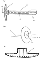
- FIG. 1 A first embodiment of an inventive fastener is in FIG. 1 shown. It has an approximately cylindrical shaft 20, on the back of a retaining plate 10 is seconded.
- the holding plate 10 is larger in diameter than the shaft 20, that is, it extends farther from the longitudinal axis 100 of the fastener than the shank 20.
- a bore 21 is provided, the back to the holding plate 10, the means to that side of the holding plate 10 back, which faces away from the shaft 20, is open.
- the bore 21 has a cross-sectional taper.
- the shaft 20 is introduced with its tip portion 29 ahead through an insulating plate into a borehole in a building wall and anchored there.
- the insulating plate on the shaft 20 and thus secured to the building wall against falling in the direction of the longitudinal axis 100.
- the shaft 20 can be secured by a non-illustrated rod-like expansion element in the building wall, which is inserted into the bore 21 to the cross-sectional taper in the tip portion 29 of the shaft 20 and there radially expands the shaft 20 and pressed with the borehole wall.
- the shaft 20 can also be secured alone by means of its inherent elasticity in the borehole. In such an embodiment, in which the fastening element acts as a nail element, the expansion element can be omitted.
- the holding plate 10 on a foam material.
- the holding plate 10 may have a foamed core structure and a solid boundary layer.
- FIG. 2 A further embodiment of a fastening element according to the invention is shown in FIG FIG. 2 shown.
- the holding plate 10 is formed in two parts with an inner inner plate 11 and an outer expansion plate 12.
- the inner plate is directly connected to the shaft 20.
- the outer diameter enlarger plate 12 is held indirectly on the inner plate 11 on the shaft 20.
- Both the inner plate 11 and the extension plate 12, or also only one of these two plates 11 and 12, according to the invention may comprise a foam material, in particular a foamed core structure and a solid surface layer.
- the retaining plate 10, in particular the inner plate 11 and / or the expansion plate 12 described above, can be produced by foam injection molding.
- a plastic melt is injected into a cavity of a molding tool and, after the molten plastic has been injected into the cavity, the cavity is opened by the desired degree of foaming.
- FIG. 3 indicated where the position of the cavity with a dotted line in time before the tool opening and a solid line, the outline of the finished holding plate 10 is shown.
Landscapes
- Physics & Mathematics (AREA)
- Engineering & Computer Science (AREA)
- Architecture (AREA)
- Acoustics & Sound (AREA)
- Electromagnetism (AREA)
- Civil Engineering (AREA)
- Structural Engineering (AREA)
- Building Environments (AREA)
- Connection Of Plates (AREA)
Abstract

Description
- Die Erfindung betrifft ein Befestigungselement zum Befestigen von Dämmstoffplatten an Gebäudewänden, insbesondere an Gebäudeaussenwänden, gemäss dem Oberbegriff des Anspruchs 1, sowie ein Verfahren zur Herstellung eines Haltetellers für solch ein Befestigungselement . Ein gattungsgemässes Befestigungselement ist ausgestattet mit einem Schaft zum Verankern des Befestigungselements in einem Loch in der Gebäudewand, und mit einem Halteteller zum Sichern einer Dämmstoffplatte am Schaft.
- Gattungsgemässe Befestigungselemente werden verwendet, um Dämmstoffplatten eines Wärmedämmverbundsystems, beispielsweise aus einem Schaumstoff oder einem Fasermaterial, an Gebäudewänden anzubringen. Ein solches Befestigungselement ist beispielsweise aus der
DE 7505392 U1 bekannt. - Aufgabe der Erfindung ist es, ein Befestigungselement anzugeben, welches bei hoher Zuverlässigkeit und guten mechanischen und thermischen Eigenschaften besonders günstig in der Herstellung ist, sowie ein entsprechendes Herstellungsverfahren anzugeben.
- Die Aufgabe wird erfindungsgemäss durch ein Befestigungselement mit den Merkmalen des Anspruchs 1 und ein Verfahren zur Herstellung eines Haltetellers für ein solches Befestigungselement gemäss Anspruch 5 gelöst. Bevorzugte Ausführungsformen sind in den jeweils abhängigen Ansprüchen angegeben.
- Ein erfindungsgemässes Befestigungselement ist dadurch gekennzeichnet, dass der Halteteller zumindest bereichsweise ein Schaumstoffmaterial aufweist.
- Ein Grundgedanke der Erfindung kann darin gesehen werden, zumindest einen Bereich des Haltetellers aus Schaumstoff auszuführen, also insbesondere aus einem Werkstoff mit über die gesamte Masse verteilten Zellen und/oder einer Rohdichte, die niedriger ist, als die Dichte der Gerüstsubstanz. Es hat sich gezeigt, dass durch Verwendung eines Schaumstoffs verglichen mit üblichen Haltetellern aus Vollkunststoff Kunststoffmaterial eingespart werden kann, ohne dass wesentliche Einbussen bei der Haltetellerfestigkeit und Haltetellersteifigkeit hingenommen werden müssen. Darüber hinaus kann die Verwendung eines Schaumstoffs fertigungstechnische Vorteile haben. Insbesondere kann durch die zum Aufschäumen regelmässig erforderliche Treibmittelbeladung die Fliessfähigkeit der Schmelze erhöht und somit die vollständige Füllung der Werkzeugkavität des zur Herstellung des Tellers verwendeten Formwerkzeugs erleichtert sein. Schliesslich können durch die Verwendung eines Schaumstoffs auch nachteilige Wärmebrücken vermieden werden.
- Der Halteteller kann auch vollständig aus einem Schaumstoffmaterial bestehen. Der Schaft besteht vorzugsweise zumindest bereichsweise aus einem Vollmaterial, da dieses zum Aufnehmen der dort auftretenden Kräfte besonders gut geeignet ist. Der Halteteller ist durchmessergrösser als der Schaft.
- Besonders vorteilhaft ist es, dass der Halteteller mehrteilig mit einem radial innenliegenden Innenteller und einem radial aussenliegenden Erweiterungsteller ausgebildet ist, wobei vorzugsweise der Erweiterungsteller zumindest bereichsweise ein Schaumstoffmaterial aufweist. Ein solches mehrteiliges System mit Innenteller und Erweiterungsteller kann in besonders einfacher Wiese an die Erfordernisse unterschiedlicher Dämmstoffplatten angepasst werden. Erfindungsgemäss können der Innenteller, der Erweiterungsteller oder sowohl der Innenteller als auch der Erweiterungsteller zumindest bereichsweise ein Schaumstoffmaterial aufweisen. Der Schaft ist vorzugsweise am Innenteller angeordnet. Die Radialrichtung kann insbesondere auf die Längsachse des Schafts und/oder des Befestigungselements bezogen sein.
- Weiterhin ist es vorteilhaft, dass der Halteteller Bereiche aufweist, in denen die Kernporosität grösser ist als die Randporosität und/oder in denen die Porosität mit zunehmender Tiefe, also mit zunehmendem Abstand von der Oberfläche des Haltetellers zunimmt und/oder in denen die Rohdichte mit zunehmender Tiefe, also mit zunehmendem Abstand von der Oberfläche des Haltetellers abnimmt. Unter der Porosität kann insbesondere in fachüblicher Weise das Verhältnis von Hohlraumvolumen zu Gesamtvolumen verstanden werden. Insbesondere kann der Halteteller Bereiche mit geschäumter Kernstruktur und fester Randschicht aufweisen. Hierdurch kann in fertigungstechnisch besonders einfacher Weise ein besonders beständiger Halteteller erhalten werden.
- Das Befestigungselement kann als Spreizdübel ausgeführt sein. Demgemäss kann es vorteilhaft sein, dass der Schaft eine Bohrung aufweist, und dass ein Expansionskörper vorgesehen ist, der zum Aufweiten des Schaftes in die Bohrung einführbar ist. Durch Aufweiten des Schaftes wird dieser im Loch in der Gebäudewand gesichert. Alternativ kann das Befestigungselement auch ein Nagelelement sein, welches alleine aufgrund seiner Eigenelastizität im Loch in der Gebäudewand hält.
- Die Erfindung betrifft auch ein Verfahren zum Herstellen eines Haltetellers, insbesondere eines Innentellers oder eines Erweiterungstellers, für ein erfindungsgemässes Befestigungselement, insbesondere ein Schaumspritzgiessverfahren. Bei dem Verfahren wird eine treibmittelbeladene Kunststoffschmelze in eine Kavität eines Formwerkzeugs eingebracht und die Kavität anschliessend, insbesondere vor dem Aushärten des Kunststoffs, zumindest teilweise, vorzugsweise nur teilweise, geöffnet und dabei die Kunststoffschmelze aufgeschäumt. Es kann also vorgesehen sein, die Kunststoffschmelze mit einem Treibmittel zu beladen und nach dem Einspritzen der Kunststoffschmelze in die Kavität des Formwerkzeugs und während des Aufschäumens der Kunststoffmasse die Kavität um einen gewünschten Aufschäumgrad zu öffnen. Hierdurch kann in besonders einfacher Art und Weise ein Halteteller mit geschäumter Kernstruktur und fester Randschicht erhalten werden. Bei dem Treibmittel kann es sich zum Beispiel um CO2 oder Natriumbikarbonat handeln.
- Besonders vorteilhaft ist es, dass die Kavität während des Aufschäumens der Kunststoffschmelze auf der Seite des Erweiterungstellers, die dem Schaft abgewandt ist, geöffnet wird, und/oder auf der gegenüberliegenden Seite, also der Seite des Erweiterungstellers, die dem Schaft zugewandt ist, nicht geöffnet wird. Hierdurch kann eine Schaumstruktur erhalten werden, die zur Befestigung von Dämmstoffplatten an einer Gebäudewand besonders gut geeignet ist. Sofern noch kein Schaft vorhanden ist, kann vorgesehen sein, dass die Kavität während des Aufschäumens der Kunststoffschmelze auf der Seite des Erweiterungstellers geöffnet wird, die dem Befestigungsbereich für den Schaft abgewandt ist und oder auf der gegenüberliegenden Seite nicht geöffnet wird.
- Die Erfindung wird nachfolgend anhand bevorzugter Ausführungsbeispiele näher erläutert, die schematisch in den beiliegenden Figuren dargestellt sind, wobei einzelne Merkmale der nachfolgend gezeigten Ausführungsbeispiele im Rahmen der Erfindung grundsätzlich einzeln oder in beliebiger Kombination realisiert werden können. In den Figuren zeigen schematisch:
- Figur 1:
- ein erstes Ausführungsbeispiel eines erfindungsgemässen Befestigungselements im Längsschnitt;
- Figur 2:
- eine perspektivische Darstellung eines zweiten Ausführungsbeispiels eines erfindungsgemässen Befestigungselements; und
- Figur 3:
- eine schematische Darstellung des Haltetellers des Ausführungsbeispiels aus Figur 1 und seiner Position in der Kavität des Formwerkzeugs bei seiner Herstellung.
- Ein erstes Ausführungsbeispiel eines erfindungsgemässen Befestigungselements ist in
Figur 1 dargestellt. Es weist einen etwa zylindrischen Schaft 20 auf, an dessen Rückseite ein Halteteller 10 abgeordnet ist. Der Halteteller 10 ist durchmessergrösser als der Schaft 20, das heisst er erstreckt sich weiter von der Längsachse 100 des Befestigungselements hinweg als der Schaft 20. Im Schaft 20 und im Halteteller 10 ist eine Bohrung 21 vorgesehen, die zur Rückseite des Haltetellers 10 hin, das heisst zur derjenigen Seite des Haltetellers 10 hin, welche dem Schaft 20 abgewandt ist, offen ist. Im Spitzenbereich 29 des Schaftes 20, also in dem Bereich, welcher dem Halteteller 10 entgegengesetzt liegt, weist die Bohrung 21 eine Querschnittsverjüngung auf. - Bei der Montage des Befestigungselements wird der Schaft 20 mit seinem Spitzenbereich 29 voran durch eine Dämmstoffplatte hindurch in ein Bohrloch in einer Gebäudewand eingeführt und dort verankert. Durch den Halteteller 10 wird die Dämmstoffplatte am Schaft 20 und damit an der Gebäudewand gegen ein Abfallen in Richtung der Längsachse 100 gesichert. Bei der dargestellten Ausführungsform kann der Schaft 20 durch ein nicht dargestelltes stabartiges Expansionselement in der Gebäudewand gesichert werden, welches in die Bohrung 21 bis in die Querschnittsverjüngung im Spitzenbereich 29 des Schafts 20 eingeführt wird und dort den Schaft 20 radial aufweitet und mit der Bohrlochwand verpresst. In einer anderen Ausführungsform kann der Schaft 20 auch alleine mittels seiner Eigenelastizität im Bohrloch gesichert werden. Bei einer solchen Ausführungsform, bei der das Befestigungselement als Nagelelement wirkt, kann das Expansionselement entfallen.
- Wie in
Figur 1 angedeutet ist, weist der Halteteller 10 ein Schaumstoffmaterial auf. Insbesondere kann der Halteteller 10 eine geschäumte Kernstruktur und eine feste Randschicht aufweisen. - Ein weiteres Ausführungsbeispiel eines erfindungsgemässen Befestigungselements ist in
Figur 2 dargestellt. Gemäss dieser Ausführungsform ist der Halteteller 10 zweiteilig mit einem innenliegenden Innenteller 11 und einem aussenliegenden Erweiterungsteller 12 ausgebildet. Der Innenteller ist dabei unmittelbar mit dem Schaft 20 verbunden. Der aussenliegende durchmessergrössere Erweiterungsteller 12 wird mittelbar über den Innenteller 11 am Schaft 20 gehalten. Sowohl der Innenteller 11 als auch der Erweiterungsteller 12, oder auch nur einer dieser beiden Teller 11 und 12, kann erfindungsgemäss ein Schaumstoffmaterial aufweisen, insbesondere eine geschäumte Kernstruktur und eine feste Randschicht. - Die zuvor beschriebenen Halteteller 10, insbesondere der Innenteller 11 oder/und der Erweiterungsteller 12, können im Schaumspritzgiessverfahren hergestellt werden. Hierbei wird eine Kunststoffschmelze treibmittelbeladen in eine Kavität eines Formwerkzeugs eingespritzt und nach dem Einspritzen der Kunststoffschmelze in die Kavität wird die Kavität um den gewünschten Aufschäumgrad geöffnet. Dies ist in
Figur 3 angedeutet, wo mit Strichlinie die Position der Kavität zeitlich vor der Werkzeugöffnung und mit durchgezogener Linie der Umriss des fertigen Haltetellers 10 dargestellt ist. Durch das besagte Verfahren kann ein Halteteller 10 mit geschäumter Kernstruktur und fester Randschicht erhalten werden.
Claims (6)
- Befestigungselement zum Befestigen von Dämmstoffplatten an Gebäudewänden,
mit einem Schaft (20) zum Verankern des Befestigungselements in einem Loch in der Gebäudewand, und
mit einem Halteteller (10) zum Sichern einer Dämmstoffplatte am Schaft (20),
dadurch gekennzeichnet,
dass der Halteteller (10) zumindest bereichsweise ein Schaumstoffmaterial aufweist. - Befestigungselement nach Anspruch 1,
dadurch gekennzeichnet,
dass der Halteteller (10) mehrteilig mit einem radial innenliegenden Innenteller (11) und einem radial aussenliegenden Erweiterungsteller (12) ausgebildet ist, und dass der Erweiterungsteller (12) zumindest bereichsweise ein Schaumstoffmaterial aufweist. - Befestigungselement nach einem der vorstehenden Ansprüche,
dadurch gekennzeichnet,
dass der Halteteller (10) Bereiche aufweist, in denen die Porosität mit zunehmender Tiefe zunimmt. - Befestigungselement nach einem der vorstehenden Ansprüche,
dadurch gekennzeichnet,
dass der Schaft (20) eine Bohrung (21) aufweist und dass ein Expansionskörper vorgesehen ist, der zum Aufweiten des Schaftes (20) in die Bohrung (21) einführbar ist, oder
dass das Befestigungselement ein Nagelelement ist. - Verfahren zum Herstellen eines Haltetellers (10), insbesondere eines Innentellers (11) oder eines Erweiterungstellers (12), für ein Befestigungselement nach einem der vorstehenden Ansprüche, bei dem
eine treibmittelbeladene Kunststoffschmelze in eine Kavität eines Formwerkzeugs eingebracht wird, und
die Kavität anschliessend zumindest teilweise geöffnet wird und dabei die Kunststoffschmelze aufgeschäumt wird. - Verfahren nach Anspruch 5,
dadurch gekennzeichnet,
dass die Kavität während des Aufschäumens der Kunststoffschmelze auf der Seite des Erweiterungstellers (12), die dem Schaft (20) abgewandt ist, geöffnet wird.
Priority Applications (1)
| Application Number | Priority Date | Filing Date | Title |
|---|---|---|---|
| EP13178297.1A EP2832933B1 (de) | 2013-07-29 | 2013-07-29 | Befestigungselement |
Applications Claiming Priority (1)
| Application Number | Priority Date | Filing Date | Title |
|---|---|---|---|
| EP13178297.1A EP2832933B1 (de) | 2013-07-29 | 2013-07-29 | Befestigungselement |
Publications (2)
| Publication Number | Publication Date |
|---|---|
| EP2832933A1 true EP2832933A1 (de) | 2015-02-04 |
| EP2832933B1 EP2832933B1 (de) | 2017-07-26 |
Family
ID=48875592
Family Applications (1)
| Application Number | Title | Priority Date | Filing Date |
|---|---|---|---|
| EP13178297.1A Active EP2832933B1 (de) | 2013-07-29 | 2013-07-29 | Befestigungselement |
Country Status (1)
| Country | Link |
|---|---|
| EP (1) | EP2832933B1 (de) |
Citations (2)
| Publication number | Priority date | Publication date | Assignee | Title |
|---|---|---|---|---|
| DE7505392U (de) | 1975-06-26 | Buschke R | Befestigungsvorrichtung für Dämmstoff-Platten | |
| DE10139261A1 (de) * | 2001-08-09 | 2003-03-06 | Heinrich August Kleine | Wandelement sowie Verfahren zu dessen Herstellung |
Family Cites Families (1)
| Publication number | Priority date | Publication date | Assignee | Title |
|---|---|---|---|---|
| DE102006042052B4 (de) * | 2005-09-07 | 2010-04-29 | Koelner Deutschland Gmbh | Isolierplattendübel |
-
2013
- 2013-07-29 EP EP13178297.1A patent/EP2832933B1/de active Active
Patent Citations (2)
| Publication number | Priority date | Publication date | Assignee | Title |
|---|---|---|---|---|
| DE7505392U (de) | 1975-06-26 | Buschke R | Befestigungsvorrichtung für Dämmstoff-Platten | |
| DE10139261A1 (de) * | 2001-08-09 | 2003-03-06 | Heinrich August Kleine | Wandelement sowie Verfahren zu dessen Herstellung |
Also Published As
| Publication number | Publication date |
|---|---|
| EP2832933B1 (de) | 2017-07-26 |
Similar Documents
| Publication | Publication Date | Title |
|---|---|---|
| DE69516864T2 (de) | Hochisolierende verbindungsstäbe und verfahren zu ihrer herstellung und ihrer anwendung in hochisolierten zusammengesetzten wänden | |
| EP3695062B1 (de) | Ankerelement, betonbauteil mit ankerelement und herstellungsverfahren | |
| DE3800833A1 (de) | Verbundduebel | |
| CH362585A (de) | Verfahren zur Herstellung von Dornbruchhohlnietverbindungen und Dornbruchhohlniet zu seiner Durchführung | |
| CH708361A1 (de) | Fassadenanker. | |
| EP3578832A1 (de) | Verfahren zum anordnen einer porenbetonschraube in porenbeton, verwendung und anordnung | |
| EP3079876B1 (de) | Verfahren zur herstellung eines fahrzeug-karosserieelements sowie fahrzeug karosserieelement | |
| EP2832933B1 (de) | Befestigungselement | |
| DE102007043031A1 (de) | Dämmstoffdübel | |
| WO2020001909A1 (de) | Kupplungselement mit verankerungsstruktur für ein schaumbauteil | |
| EP2924302B1 (de) | Spreizdübel | |
| AT520437B1 (de) | Verkleidungselement für ein Gebäude sowie Verfahren zur Herstellung eines solchen Verkleidungselementes | |
| DE102007043568A1 (de) | Befestigungselement für Lochbaustoffe | |
| DE102012001647B4 (de) | Verfahren zur Versteifung eines Strukturbauteils eines Kraftfahrzeugs | |
| DE102015219453B4 (de) | Verfahren zum Herstellen eines schaumgefüllten, faserverstärkten Kunststoffhohlprofils | |
| DE7730164U1 (de) | ||
| WO2017194543A1 (de) | Verbindungselement für ein hohlwandelement | |
| DE102011109601A1 (de) | Verbindungsanordnung und Verfahren zum Verbinden zweier Bauteile | |
| DE102017126056A1 (de) | Verfahren zum Befestigen eines Dämmstoffelements und Dämmstoffdübel | |
| DE2747779C2 (de) | Dübel zum Verankern in Hohlbausteinen, Platten und dergleichen Aufnahmeteilen | |
| EP0535411B1 (de) | Klebstoffpatrone für einen Verbunddübel und Verfahren zu ihrer Herstellung | |
| DE102017121305A1 (de) | Spreizanker für dünne Platten | |
| DE102023106642A1 (de) | System und Verfahren zur Befestigung eines Verankerungselements in einem Hohlprofil eines Fensters oder einer Tür | |
| DE102022106646A1 (de) | Dämmstoffdübel, Urformwerkzeug und Verfahren zur Herstellung des Dämmstoffdübels | |
| DE102013101189A1 (de) | Befestigungselement |
Legal Events
| Date | Code | Title | Description |
|---|---|---|---|
| 17P | Request for examination filed |
Effective date: 20130729 |
|
| AK | Designated contracting states |
Kind code of ref document: A1 Designated state(s): AL AT BE BG CH CY CZ DE DK EE ES FI FR GB GR HR HU IE IS IT LI LT LU LV MC MK MT NL NO PL PT RO RS SE SI SK SM TR |
|
| AX | Request for extension of the european patent |
Extension state: BA ME |
|
| PUAI | Public reference made under article 153(3) epc to a published international application that has entered the european phase |
Free format text: ORIGINAL CODE: 0009012 |
|
| R17P | Request for examination filed (corrected) |
Effective date: 20150804 |
|
| RBV | Designated contracting states (corrected) |
Designated state(s): AL AT BE BG CH CY CZ DE DK EE ES FI FR GB GR HR HU IE IS IT LI LT LU LV MC MK MT NL NO PL PT RO RS SE SI SK SM TR |
|
| 17Q | First examination report despatched |
Effective date: 20160531 |
|
| GRAP | Despatch of communication of intention to grant a patent |
Free format text: ORIGINAL CODE: EPIDOSNIGR1 |
|
| INTG | Intention to grant announced |
Effective date: 20170421 |
|
| GRAS | Grant fee paid |
Free format text: ORIGINAL CODE: EPIDOSNIGR3 |
|
| GRAA | (expected) grant |
Free format text: ORIGINAL CODE: 0009210 |
|
| AK | Designated contracting states |
Kind code of ref document: B1 Designated state(s): AL AT BE BG CH CY CZ DE DK EE ES FI FR GB GR HR HU IE IS IT LI LT LU LV MC MK MT NL NO PL PT RO RS SE SI SK SM TR |
|
| REG | Reference to a national code |
Ref country code: GB Ref legal event code: FG4D Free format text: NOT ENGLISH |
|
| REG | Reference to a national code |
Ref country code: CH Ref legal event code: EP |
|
| REG | Reference to a national code |
Ref country code: AT Ref legal event code: REF Ref document number: 912512 Country of ref document: AT Kind code of ref document: T Effective date: 20170815 |
|
| REG | Reference to a national code |
Ref country code: IE Ref legal event code: FG4D Free format text: LANGUAGE OF EP DOCUMENT: GERMAN |
|
| REG | Reference to a national code |
Ref country code: DE Ref legal event code: R096 Ref document number: 502013007850 Country of ref document: DE |
|
| REG | Reference to a national code |
Ref country code: NL Ref legal event code: MP Effective date: 20170726 |
|
| REG | Reference to a national code |
Ref country code: LT Ref legal event code: MG4D |
|
| PG25 | Lapsed in a contracting state [announced via postgrant information from national office to epo] |
Ref country code: LT Free format text: LAPSE BECAUSE OF FAILURE TO SUBMIT A TRANSLATION OF THE DESCRIPTION OR TO PAY THE FEE WITHIN THE PRESCRIBED TIME-LIMIT Effective date: 20170726 Ref country code: HR Free format text: LAPSE BECAUSE OF FAILURE TO SUBMIT A TRANSLATION OF THE DESCRIPTION OR TO PAY THE FEE WITHIN THE PRESCRIBED TIME-LIMIT Effective date: 20170726 Ref country code: NL Free format text: LAPSE BECAUSE OF FAILURE TO SUBMIT A TRANSLATION OF THE DESCRIPTION OR TO PAY THE FEE WITHIN THE PRESCRIBED TIME-LIMIT Effective date: 20170726 Ref country code: FI Free format text: LAPSE BECAUSE OF FAILURE TO SUBMIT A TRANSLATION OF THE DESCRIPTION OR TO PAY THE FEE WITHIN THE PRESCRIBED TIME-LIMIT Effective date: 20170726 Ref country code: SE Free format text: LAPSE BECAUSE OF FAILURE TO SUBMIT A TRANSLATION OF THE DESCRIPTION OR TO PAY THE FEE WITHIN THE PRESCRIBED TIME-LIMIT Effective date: 20170726 Ref country code: NO Free format text: LAPSE BECAUSE OF FAILURE TO SUBMIT A TRANSLATION OF THE DESCRIPTION OR TO PAY THE FEE WITHIN THE PRESCRIBED TIME-LIMIT Effective date: 20171026 |
|
| PG25 | Lapsed in a contracting state [announced via postgrant information from national office to epo] |
Ref country code: PL Free format text: LAPSE BECAUSE OF FAILURE TO SUBMIT A TRANSLATION OF THE DESCRIPTION OR TO PAY THE FEE WITHIN THE PRESCRIBED TIME-LIMIT Effective date: 20170726 Ref country code: RS Free format text: LAPSE BECAUSE OF FAILURE TO SUBMIT A TRANSLATION OF THE DESCRIPTION OR TO PAY THE FEE WITHIN THE PRESCRIBED TIME-LIMIT Effective date: 20170726 Ref country code: BG Free format text: LAPSE BECAUSE OF FAILURE TO SUBMIT A TRANSLATION OF THE DESCRIPTION OR TO PAY THE FEE WITHIN THE PRESCRIBED TIME-LIMIT Effective date: 20171026 Ref country code: IS Free format text: LAPSE BECAUSE OF FAILURE TO SUBMIT A TRANSLATION OF THE DESCRIPTION OR TO PAY THE FEE WITHIN THE PRESCRIBED TIME-LIMIT Effective date: 20171126 Ref country code: LV Free format text: LAPSE BECAUSE OF FAILURE TO SUBMIT A TRANSLATION OF THE DESCRIPTION OR TO PAY THE FEE WITHIN THE PRESCRIBED TIME-LIMIT Effective date: 20170726 Ref country code: ES Free format text: LAPSE BECAUSE OF FAILURE TO SUBMIT A TRANSLATION OF THE DESCRIPTION OR TO PAY THE FEE WITHIN THE PRESCRIBED TIME-LIMIT Effective date: 20170726 Ref country code: GR Free format text: LAPSE BECAUSE OF FAILURE TO SUBMIT A TRANSLATION OF THE DESCRIPTION OR TO PAY THE FEE WITHIN THE PRESCRIBED TIME-LIMIT Effective date: 20171027 |
|
| PG25 | Lapsed in a contracting state [announced via postgrant information from national office to epo] |
Ref country code: CZ Free format text: LAPSE BECAUSE OF FAILURE TO SUBMIT A TRANSLATION OF THE DESCRIPTION OR TO PAY THE FEE WITHIN THE PRESCRIBED TIME-LIMIT Effective date: 20170726 Ref country code: DK Free format text: LAPSE BECAUSE OF FAILURE TO SUBMIT A TRANSLATION OF THE DESCRIPTION OR TO PAY THE FEE WITHIN THE PRESCRIBED TIME-LIMIT Effective date: 20170726 Ref country code: MC Free format text: LAPSE BECAUSE OF FAILURE TO SUBMIT A TRANSLATION OF THE DESCRIPTION OR TO PAY THE FEE WITHIN THE PRESCRIBED TIME-LIMIT Effective date: 20170726 Ref country code: RO Free format text: LAPSE BECAUSE OF FAILURE TO SUBMIT A TRANSLATION OF THE DESCRIPTION OR TO PAY THE FEE WITHIN THE PRESCRIBED TIME-LIMIT Effective date: 20170726 |
|
| REG | Reference to a national code |
Ref country code: DE Ref legal event code: R097 Ref document number: 502013007850 Country of ref document: DE |
|
| REG | Reference to a national code |
Ref country code: IE Ref legal event code: MM4A |
|
| PG25 | Lapsed in a contracting state [announced via postgrant information from national office to epo] |
Ref country code: SM Free format text: LAPSE BECAUSE OF FAILURE TO SUBMIT A TRANSLATION OF THE DESCRIPTION OR TO PAY THE FEE WITHIN THE PRESCRIBED TIME-LIMIT Effective date: 20170726 Ref country code: SK Free format text: LAPSE BECAUSE OF FAILURE TO SUBMIT A TRANSLATION OF THE DESCRIPTION OR TO PAY THE FEE WITHIN THE PRESCRIBED TIME-LIMIT Effective date: 20170726 Ref country code: EE Free format text: LAPSE BECAUSE OF FAILURE TO SUBMIT A TRANSLATION OF THE DESCRIPTION OR TO PAY THE FEE WITHIN THE PRESCRIBED TIME-LIMIT Effective date: 20170726 Ref country code: IT Free format text: LAPSE BECAUSE OF FAILURE TO SUBMIT A TRANSLATION OF THE DESCRIPTION OR TO PAY THE FEE WITHIN THE PRESCRIBED TIME-LIMIT Effective date: 20170726 |
|
| PLBE | No opposition filed within time limit |
Free format text: ORIGINAL CODE: 0009261 |
|
| STAA | Information on the status of an ep patent application or granted ep patent |
Free format text: STATUS: NO OPPOSITION FILED WITHIN TIME LIMIT |
|
| REG | Reference to a national code |
Ref country code: BE Ref legal event code: MM Effective date: 20170731 |
|
| GBPC | Gb: european patent ceased through non-payment of renewal fee |
Effective date: 20171026 |
|
| PG25 | Lapsed in a contracting state [announced via postgrant information from national office to epo] |
Ref country code: LU Free format text: LAPSE BECAUSE OF NON-PAYMENT OF DUE FEES Effective date: 20170729 |
|
| 26N | No opposition filed |
Effective date: 20180430 |
|
| REG | Reference to a national code |
Ref country code: FR Ref legal event code: ST Effective date: 20180607 |
|
| PG25 | Lapsed in a contracting state [announced via postgrant information from national office to epo] |
Ref country code: IE Free format text: LAPSE BECAUSE OF NON-PAYMENT OF DUE FEES Effective date: 20170729 Ref country code: GB Free format text: LAPSE BECAUSE OF NON-PAYMENT OF DUE FEES Effective date: 20171026 |
|
| PG25 | Lapsed in a contracting state [announced via postgrant information from national office to epo] |
Ref country code: SI Free format text: LAPSE BECAUSE OF FAILURE TO SUBMIT A TRANSLATION OF THE DESCRIPTION OR TO PAY THE FEE WITHIN THE PRESCRIBED TIME-LIMIT Effective date: 20170726 Ref country code: BE Free format text: LAPSE BECAUSE OF NON-PAYMENT OF DUE FEES Effective date: 20170731 Ref country code: FR Free format text: LAPSE BECAUSE OF NON-PAYMENT OF DUE FEES Effective date: 20170926 |
|
| PG25 | Lapsed in a contracting state [announced via postgrant information from national office to epo] |
Ref country code: MT Free format text: LAPSE BECAUSE OF FAILURE TO SUBMIT A TRANSLATION OF THE DESCRIPTION OR TO PAY THE FEE WITHIN THE PRESCRIBED TIME-LIMIT Effective date: 20170726 |
|
| PG25 | Lapsed in a contracting state [announced via postgrant information from national office to epo] |
Ref country code: HU Free format text: LAPSE BECAUSE OF FAILURE TO SUBMIT A TRANSLATION OF THE DESCRIPTION OR TO PAY THE FEE WITHIN THE PRESCRIBED TIME-LIMIT; INVALID AB INITIO Effective date: 20130729 |
|
| PG25 | Lapsed in a contracting state [announced via postgrant information from national office to epo] |
Ref country code: CY Free format text: LAPSE BECAUSE OF FAILURE TO SUBMIT A TRANSLATION OF THE DESCRIPTION OR TO PAY THE FEE WITHIN THE PRESCRIBED TIME-LIMIT Effective date: 20170726 |
|
| PG25 | Lapsed in a contracting state [announced via postgrant information from national office to epo] |
Ref country code: MK Free format text: LAPSE BECAUSE OF FAILURE TO SUBMIT A TRANSLATION OF THE DESCRIPTION OR TO PAY THE FEE WITHIN THE PRESCRIBED TIME-LIMIT Effective date: 20170726 |
|
| PG25 | Lapsed in a contracting state [announced via postgrant information from national office to epo] |
Ref country code: TR Free format text: LAPSE BECAUSE OF FAILURE TO SUBMIT A TRANSLATION OF THE DESCRIPTION OR TO PAY THE FEE WITHIN THE PRESCRIBED TIME-LIMIT Effective date: 20170726 |
|
| PG25 | Lapsed in a contracting state [announced via postgrant information from national office to epo] |
Ref country code: PT Free format text: LAPSE BECAUSE OF FAILURE TO SUBMIT A TRANSLATION OF THE DESCRIPTION OR TO PAY THE FEE WITHIN THE PRESCRIBED TIME-LIMIT Effective date: 20170726 |
|
| PG25 | Lapsed in a contracting state [announced via postgrant information from national office to epo] |
Ref country code: AL Free format text: LAPSE BECAUSE OF FAILURE TO SUBMIT A TRANSLATION OF THE DESCRIPTION OR TO PAY THE FEE WITHIN THE PRESCRIBED TIME-LIMIT Effective date: 20170726 |
|
| PGFP | Annual fee paid to national office [announced via postgrant information from national office to epo] |
Ref country code: DE Payment date: 20250722 Year of fee payment: 13 |
|
| PGFP | Annual fee paid to national office [announced via postgrant information from national office to epo] |
Ref country code: AT Payment date: 20250722 Year of fee payment: 13 |
|
| PGFP | Annual fee paid to national office [announced via postgrant information from national office to epo] |
Ref country code: CH Payment date: 20250801 Year of fee payment: 13 |