EP2831900B1 - Polarized electromagnetic relay and method for production thereof - Google Patents
Polarized electromagnetic relay and method for production thereof Download PDFInfo
- Publication number
- EP2831900B1 EP2831900B1 EP13713418.5A EP13713418A EP2831900B1 EP 2831900 B1 EP2831900 B1 EP 2831900B1 EP 13713418 A EP13713418 A EP 13713418A EP 2831900 B1 EP2831900 B1 EP 2831900B1
- Authority
- EP
- European Patent Office
- Prior art keywords
- pole
- relay
- magnetic flux
- permanent magnet
- armature
- Prior art date
- Legal status (The legal status is an assumption and is not a legal conclusion. Google has not performed a legal analysis and makes no representation as to the accuracy of the status listed.)
- Active
Links
- 238000004519 manufacturing process Methods 0.000 title claims description 6
- 230000005291 magnetic effect Effects 0.000 claims description 59
- 230000004907 flux Effects 0.000 claims description 46
- 239000002243 precursor Substances 0.000 claims description 14
- 230000008878 coupling Effects 0.000 claims description 6
- 238000010168 coupling process Methods 0.000 claims description 6
- 238000005859 coupling reaction Methods 0.000 claims description 6
- 238000000034 method Methods 0.000 claims description 4
- 230000004308 accommodation Effects 0.000 claims 13
- 230000005415 magnetization Effects 0.000 description 8
- 230000005294 ferromagnetic effect Effects 0.000 description 7
- XEEYBQQBJWHFJM-UHFFFAOYSA-N Iron Chemical compound [Fe] XEEYBQQBJWHFJM-UHFFFAOYSA-N 0.000 description 4
- 239000000956 alloy Substances 0.000 description 4
- 229910045601 alloy Inorganic materials 0.000 description 4
- 238000005192 partition Methods 0.000 description 3
- 238000004804 winding Methods 0.000 description 3
- 229910052742 iron Inorganic materials 0.000 description 2
- 239000000853 adhesive Substances 0.000 description 1
- 238000004026 adhesive bonding Methods 0.000 description 1
- 230000001070 adhesive effect Effects 0.000 description 1
- 230000000712 assembly Effects 0.000 description 1
- 238000000429 assembly Methods 0.000 description 1
- 238000005452 bending Methods 0.000 description 1
- 238000005266 casting Methods 0.000 description 1
- 150000001875 compounds Chemical class 0.000 description 1
- 239000000428 dust Substances 0.000 description 1
- 238000009434 installation Methods 0.000 description 1
- 239000000463 material Substances 0.000 description 1
- 239000002184 metal Substances 0.000 description 1
- 229910052751 metal Inorganic materials 0.000 description 1
- 239000002245 particle Substances 0.000 description 1
- 238000004382 potting Methods 0.000 description 1
- 238000003825 pressing Methods 0.000 description 1
- 230000035945 sensitivity Effects 0.000 description 1
- 238000003466 welding Methods 0.000 description 1
Images


Classifications
-
- H—ELECTRICITY
- H01—ELECTRIC ELEMENTS
- H01H—ELECTRIC SWITCHES; RELAYS; SELECTORS; EMERGENCY PROTECTIVE DEVICES
- H01H51/00—Electromagnetic relays
- H01H51/22—Polarised relays
- H01H51/2236—Polarised relays comprising pivotable armature, pivoting at extremity or bending point of armature
-
- H—ELECTRICITY
- H01—ELECTRIC ELEMENTS
- H01H—ELECTRIC SWITCHES; RELAYS; SELECTORS; EMERGENCY PROTECTIVE DEVICES
- H01H50/00—Details of electromagnetic relays
- H01H50/02—Bases; Casings; Covers
- H01H50/04—Mounting complete relay or separate parts of relay on a base or inside a case
- H01H50/041—Details concerning assembly of relays
-
- H—ELECTRICITY
- H01—ELECTRIC ELEMENTS
- H01H—ELECTRIC SWITCHES; RELAYS; SELECTORS; EMERGENCY PROTECTIVE DEVICES
- H01H49/00—Apparatus or processes specially adapted to the manufacture of relays or parts thereof
-
- H—ELECTRICITY
- H01—ELECTRIC ELEMENTS
- H01H—ELECTRIC SWITCHES; RELAYS; SELECTORS; EMERGENCY PROTECTIVE DEVICES
- H01H51/00—Electromagnetic relays
- H01H51/22—Polarised relays
-
- H—ELECTRICITY
- H01—ELECTRIC ELEMENTS
- H01F—MAGNETS; INDUCTANCES; TRANSFORMERS; SELECTION OF MATERIALS FOR THEIR MAGNETIC PROPERTIES
- H01F7/00—Magnets
- H01F7/06—Electromagnets; Actuators including electromagnets
- H01F7/08—Electromagnets; Actuators including electromagnets with armatures
- H01F7/121—Guiding or setting position of armatures, e.g. retaining armatures in their end position
- H01F7/122—Guiding or setting position of armatures, e.g. retaining armatures in their end position by permanent magnets
-
- Y—GENERAL TAGGING OF NEW TECHNOLOGICAL DEVELOPMENTS; GENERAL TAGGING OF CROSS-SECTIONAL TECHNOLOGIES SPANNING OVER SEVERAL SECTIONS OF THE IPC; TECHNICAL SUBJECTS COVERED BY FORMER USPC CROSS-REFERENCE ART COLLECTIONS [XRACs] AND DIGESTS
- Y10—TECHNICAL SUBJECTS COVERED BY FORMER USPC
- Y10T—TECHNICAL SUBJECTS COVERED BY FORMER US CLASSIFICATION
- Y10T29/00—Metal working
- Y10T29/49—Method of mechanical manufacture
- Y10T29/49002—Electrical device making
- Y10T29/4902—Electromagnet, transformer or inductor
- Y10T29/49073—Electromagnet, transformer or inductor by assembling coil and core
Definitions
- the invention relates to a method for producing a polarized electromagnetic relay with an electromagnet, permanent magnet, armature and actuatable switch and to a polarized electromagnetic relay produced in this way.
- Poled, electromagnetic relays are available with a three-pole permanent magnet ( WO 93/23866 ) and with two-pole permanent magnet ( U.S. 4,912,438 , U.S. 5,153,543 , US 6,670,871 B1 ).
- the electromagnet has a coil with a core and pole pieces in a yoke-shaped structure.
- this permanent magnet is arranged between the two yoke legs above the coil and parallel to the coil axis.
- This permanent magnet can be separated from a magnetized band and inserted into the coil body between the two yoke legs.
- this is magnetically connected at right angles to the coil axis with a pole in about the middle of the old core ( U.S. 4,912,438 , U.S. 5,153,543 ).
- U.S. 4,975,666 a polarized, electromagnetic relay which has a base housing open at the top, in which an electromagnetic block with coil, core and pole legs and, between the pole legs, a permanent magnet, and on the pole legs, a valve block with armature and switch elements are mounted.
- the design does not allow the permanent magnet located between the pole legs to be generated from an unmagnetized ferromagnetic precursor by magnetization, because the coil would be damaged by excessive, induced currents.
- a relay with a two-pole permanent magnet is also known ( US 6,670 871 B1 ), which extends parallel to the coil axis.
- the plate-shaped permanent magnet with poles on the top and bottom is held in an anchor plate.
- the electromagnet is housed in a two-part housing which has a trough-shaped lower part and a box-shaped upper part on which the fixed contacts of the switches and the rotating supports for the armature are located.
- the movable contact springs are embedded in the insulating anchor plate.
- a recess in the anchor plate is used to accommodate the two-pole permanent magnet. Whether the permanent magnet is embedded in the armature plate is magnetized is not disclosed in the document.
- the DE 38 02 688 A1 shows a polarized relay with an insulating base body in the form of a flat trough which has a central, elongated recess for receiving the coil of the polarized relay.
- the coil forms a structural unit with the core and pole pieces, which is built into the recess of the tub in order to work together with counter-contact elements, connection elements for armature contact springs and with coil connection elements. As a result of these elements, there is no lateral accessibility to the recess, which is therefore not designed in the manner of a drawer.
- a polarized electromagnetic relay which comprises a base body with a partition which isolates an overhead coil from a base arranged below.
- the coil with core and pole pieces as well as with winding connection elements is installed from above into the cavity of the base body, the winding connection elements reaching through recesses in the partition wall and being connected to the base of the device, which is housed in the space below the partition wall.
- a drawer-like receiving space which would have to be accessible from the side of the base body, is not provided.
- the invention is based on the object of magnetizing the permanent magnet of a polarized relay without endangering other relay parts.
- the components of the relay are designed separately in connection with special manufacturing steps, so that the permanent magnet can be magnetized without the risk of damaging the coil of the electromagnet.
- a coil assembly with coil, core and pole pieces is provided as a component of the relay, and also a carrier component in which magnetic flux parts of the magnetic system of the relay are included, including the pole pieces of the electromagnet and a bearing piece of the armature.
- These magnetic flux parts are made of soft iron and are not damaged by high magnetic field strengths.
- a one-piece or two-piece permanent magnet precursor made of non-magnetized, ferromagnetic alloy is built into the carrier component, which results in the permanent magnet by magnetization.
- the carrier component also has a receiving space into which the separately produced coil assembly, which represents the sensitive part of the electromagnet, is inserted and mounted after the permanent magnet has been magnetized. Then the remaining relay components to complete the relay are installed, including the switches operated by the relay.
- the invention also relates to a polarized electromagnetic relay which comprises an electromagnet, a pole assembly with magnetic flux parts and with a permanent magnet, a carrier component and an armature.
- the electromagnet comprises a coil assembly, which is designed as a unit with coil, core and pole pieces.
- the support component is preferably tiered and comprises an upper-side cavity as a receiving space for the pole assembly with the magnetic flux parts and the magnetized permanent magnet as well as a central slot as a receiving space for the coil assembly.
- the armature of the relay is arranged pivotably relative to the electromagnet on the carrier component and is connected to the movable switch elements.
- the electromagnetic relay is made up of a magnet system and a switch system, which are held together and protected by housing components.
- the magnet system comprises an electromagnet, which consists of a coil assembly 10 ( Fig. 4 ) and pole pieces ( Fig. 2 ) consists.
- the coil assembly 10 comprises a coil 1 wound on a coil body 5, a ferromagnetic core 2 and ferromagnetic pole pieces 3 and 4, which form a structural unit.
- the core 2 is integrally connected to one of the two pole pieces 3, 4 or to both pole pieces. Still belong to the magnet system Magnetic flux parts 7, 8, 9, a permanent magnet 11 and an armature 12.
- the magnetic flux parts 7 and 8 form the pole pieces of the electromagnet.
- the magnetic flux part 9 forms a bearing piece for the armature 12, which is designed here as a rocking armature.
- the permanent magnet 11 of the first embodiment has two poles and is arranged between the pole piece 7 and the magnetic flux part 9, while there is a magnetic flux interruption between the parts 8 and 9. It is also possible to swap the arrangement of the permanent magnet and the magnetic flux gap. The alignment of the poles of the permanent magnet with respect to the pole piece 7 or 8 and the magnetic flux part 9 is important.
- the magnetic flux parts 7, 8, 9 and the permanent magnet 11 form a pole assembly.
- connection block 6 is connected to the coil assembly 10, which is not necessary in the context of the invention.
- the connection block 6 comprises switching signal connection pins 15, 16 with bending legs 15a, 16a for direct connection to the winding ends of the coil 1.
- a test contact connection pin 25 is cranked and can thus be clamped between connection block 6 and pole piece 3.
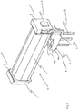
- FIG. 4 The component shown is designed to be placed in a drawer-like receiving space 42 of a storey-like support component 40 ( Fig. 3 ) to be pushed in and assembled.
- the drawer 42 has two cavity expansions 43 and 44 in order to receive and position the connection block 6 in addition to the coil assembly 10.
- the tiered support component 40 is also responsible for receiving the pole assembly, that is to say the magnetic flux parts 7, 8, 9 and the permanent magnet 11.
- an anchor-side receiving space 41 divided into niches is provided.
- the parts 7, 8, 9 and 11 are fastened in the carrier component 40 by embedding.
- Various embedding methods come into consideration, for example overmolding, gluing, pressing in.
- a fixed contact 21 is also provided, which is in electrical connection with a connection pin 26, which is also fastened in the carrier component 40 by embedding.
- the switch system contains a diagnostic switch 20 and at least one load switch 30.
- the diagnostic switch 20 comprises the fixed contact 21 and a movable contact 22 which is attached as a double contact to the fork-shaped end of a contact spring 23.
- the contact spring 23 is attached to the leg 12a of the armature 12 and is actuated by the latter.
- the movable contact 22 establishes the electrical connection with the connecting pin 25.
- test contact connection pin 25 is embedded in the support component 40 parallel to the test contact connection pin 26 (not shown) and two separate fixed contacts are provided on the top of the support component 40.
- end of the contact spring 23 is used as a bridge contact for closing the switch 20.
- the load switch 30 comprises a fixed contact 31 and a movable contact 32 which is seated on a contact spring 33 which is fastened to the carrier component 40 via a busbar 34 and is also in electrical connection with a load connection pin 35.
- the fixed contact 31 is in conductive connection with a further load connection pin 36.
- the contact spring 33 is actuated via an electrically insulating coupling member 37, the upper end of which is mechanically connected to the second leg 12b of the armature 12.
- the mechanical connection can take place via an overtravel spring 38, as shown, or by direct connection of the ends of the rocker armature 12 and the coupling member 37.
- the armature 12 In addition to its two legs 12a and 12b, the armature 12 also has a curved bearing part 12c with which the armature rests on the magnetic flux part 9, which is built as a bearing piece.
- the legs 12a, 12b of the armature 12 are of different lengths and are held by spring forces with different pole gap widths. Such spring forces are generated by the contact spring 23, the overtravel spring 38 (if present) and the contact spring 33.
- the contact spring 23 is riveted to the arm 12a of the armature and has spring extensions 23a and 23b as well as a fastening tab 23c which is welded to the bearing piece 9 in a certain angular position between armature 12 and pole surface 7.
- the overtravel spring 38 is similarly riveted firmly to the leg 12b and also has spring extensions 38a, 38b and a fastening tab 38c which is welded to the bearing piece 9. In addition to the force of the contact spring 33, it is primarily the torsional forces of the spring legs 23b and 38b, which are responsible for the overall spring behavior of the relay.
- the magnetic force of attraction on the armature 12 also plays a role, whether a monostable or a bistable relay is obtained.
- the strength of the permanent magnet 11 and the sizes of the pole faces of the pole pieces 7, 8 play a role in the forces of attraction on the legs 12a, 12b of the armature. If the magnetic attraction force in one end position of the armature is greater than the spring force effective in the lifting direction and in the other end position the magnetic attraction force is smaller than the lifting force of the springs, then there is a monostable relay. If, on the other hand, the magnetic attraction force in both end positions of the armature is greater than the spring force effective in the lifting direction, a bistable relay is present.
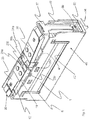
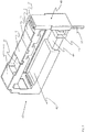
- the carrier component 40 represents the main element of the housing, there is also a housing base 50 and a housing cover 60. As in FIG Fig. 1 As shown, the carrier component 40 has a guide 46 on its front side visible there for guiding the insulating coupling member 37. This guide and the top of the relay is through the housing cover 60 according to Fig. 1 mounted relay covered. A flat cavity 45 extends along the underside of the support component 40 ( Fig. 2 ), which serves to accommodate the load contact spring 33 and its freedom of movement and which is delimited from the housing base 50 at the bottom.
- the load contact connecting pin 36 is inserted into the base part 50 and riveted to the base part by means of the fixed contact 31.
- a switch can be located on the top of the housing cover 60 in order to change the position of the armature 12 by hand.
- a second embodiment of the invention is shown. Similar components to the first embodiment are given the same reference numerals.
- the basic structure of the relay according to the second embodiment follows the first embodiment, which is why corresponding parts of the description are not repeated and only the differences are discussed.
- the permanent magnet 11 is made from two parts 11a and 11b and with a magnetic flux part 9 made of soft iron and forms a three-pole permanent magnet.
- the section 11a has the stronger coercive force compared to the section 11b.
- the two parts 11a and 11b have the same polarity towards the magnetic flux part 9, so either both are formed there as a south pole or as a north pole, while the three-pole permanent magnet 11 then shows north poles or south poles towards the outer ends of the relay.
- the magnetic flux part 9 conveys the adjacent polarity, for example the south pole when the permanent magnet faces the north pole and the north pole when the permanent magnet faces the south pole.
- the mounting of the armature 12 compared to the first embodiment is modified by a cross spring 39, the mounting of the armature 12 on the Magnet flux part 9 takes over.
- the cross spring 39 has tabs 39a, with which it is connected to the magnetic flux part 9 by welding, also a torsion bar 39b and transversely thereto a support tab 39c for supporting the armature 12.
- Another tab 39d can be attached to the cross spring 39, which serves to dampen the impact of the armature 12 on the magnetic flux part 8 and is tensioned at the same time, which is useful when the armature 12 is switched over later, since the armature then detaches more easily from the magnetic flux part 8.
- the cross spring 39 acts as a torsion spring, ie there is no bearing friction and the hysteresis losses of the spring 39 are very small.
- the second embodiment has a one-piece design of contact spring 23 and overtravel spring 38.
- the contact spring 23 is electrically conductive and connected to the electrically conductive armature 12, which in turn is connected via the electrically conductive cross spring 39 to the electrically conductive magnetic flux part 9, which in turn is in electrically conductive connection to the test contact connection pin 25.
- An intermediate piece 8a made of sheet metal or plastic is also provided in order to adapt the adhesive force of the armature 12 at the leg 12b to the magnetic flux part 8. Because of the different lengths of the legs 12a, 12b of the armature 12, the lifting forces exerted there are different, which is somewhat compensated for by the intermediate position of the part 8a.
- the polarized electromagnetic relay is manufactured and assembled in a new way.
- the individual parts shown are partially assembled into assemblies, including those in Fig. 4
- This coil assembly comprises at least the coil 1, the core 2 and the pole shoes 3 and 4.
- the individual parts shown also include a carrier component 40, which according to the invention is functionally adapted to the manufacturing method of the relay.
- the carrier component 40 namely contains an armature-side receiving space 41 for the magnetic flux parts 7, 8, 9 and the permanent magnet 11 as well as a drawer-like receiving space 42 for the coil assembly 10.
- the magnetic flux parts 7, 8 and 9 and the permanent magnet 11 can be referred to as a pole assembly, since they present the armature 12 with two outer poles and a center pole.
- the pole assembly is mounted in the receiving space 41 of the carrier component 40 and fastened, for example, by casting around it.
- the type of permanent magnet to be generated must be taken into account. If a one-piece two-pole permanent magnet is to be produced, which corresponds to the first embodiment of the relay, the procedure described is sufficient. If, on the other hand, a three-pole permanent magnet is to be generated by magnetization, the procedure is modified.
- Two precursor magnet sections 11a, 11b are used on both sides of the central magnetic flux part 9 and in contact with the adjacent magnetic flux parts 7 and 8.
- One of these precursor magnet sections, here section 11a consists of a more magnetizable alloy opposite the other section 11b. The more strongly magnetizable section 11a can also be made smaller than the less magnetizable section 11b.
- magnetization is carried out in a certain direction, as it corresponds to the stronger partial permanent magnet 11a. Then a direction opposite to the original magnetic direction, but weaker Magnetic field applied to the pole assembly, this weaker magnetic field not being sufficient to re-magnetize the permanent magnet 11a, but sufficient to re-magnetize the weaker permanent magnet 11b.
- This has the consequence that poles of the same name are opposite one another on the central magnetic flux part 9. In this way, an overall permanent magnet 11 is obtained with two poles of the same name on the outside, ie to the magnetic flux parts 7 and 8 acting as pole pieces, and an opposite pole on the central magnetic flux part 9.
- This structure forms a three-pole permanent magnet.
- the coil assembly 10 can be safely mounted in the drawer-like receiving space 42.
- the relays can be made very small, since permanent magnets with a large coercive force can be generated.
Landscapes
- Physics & Mathematics (AREA)
- Electromagnetism (AREA)
- Engineering & Computer Science (AREA)
- Manufacturing & Machinery (AREA)
- Electromagnets (AREA)
- Manufacture Of Switches (AREA)
Description
Die Erfindung bezieht sich auf ein Verfahren zur Herstellung eines gepolten elektromagnetischen Relais mit Eletromagnet, Permanentmagnet, Anker und betätigbaren Schalter sowie auf ein so hergestelltes gepoltes, elektromagnetisches Relais.The invention relates to a method for producing a polarized electromagnetic relay with an electromagnet, permanent magnet, armature and actuatable switch and to a polarized electromagnetic relay produced in this way.
Gepolte, elektromagnetische Relais gibt es in der Bauweise mit Dreipol-Permanentmagnet (
Aus
Aus
Es ist auch schon ein Relais mit Zweipol-Permanentmagnet bekannt (
Die
Aus
Um klein gebaute polarisierte Relais implementieren zu können, benötigt man sehr starke Permanentmagnete. Solche starken Permanentmagnete stehen mit Anteilen von Seltenen Erden zur Verfügung. Wegen der starken Anziehungskräfte zwischen den Magneten ist jedoch ihre Handhabung aus einem Vorrat von Einzelmagneten schwierig, nicht nur was das Haften der Magneten aneinander angeht, sondern auch die Freihaltung von Spänen und Staubteilen von den Polflächen während des Einbaus. Vom technologischen Standpunkt der Herstellung aus ist es günstiger, ein Materialstück aus einer unmagnetisierten ferromagnetischen Legierung zu verwenden und den "Vorläufer" nach Einbau in das Relais "aufzumagnetisieren". Aufmagnetisierung an Ort und Stelle mit hohen Feldstärken birgt jedoch die Gefahr in sich, dass andere Komponenten des magnetischen Systems des Relais beschädigt werden, insbesondere die Spule des Elektromagneten wegen starker, induzierter Spannungen und Strömen.In order to be able to implement small polarized relays, very strong permanent magnets are required. Such strong permanent magnets are available with a proportion of rare earths. Because of the strong attractive forces between the magnets, however, handling them from a supply of individual magnets is difficult, not only in terms of the adhesion of the magnets to one another, but also in terms of keeping chips and dust particles free from the pole faces during installation. From a technological point of view of manufacture, it is more advantageous to use a piece of material made from a non-magnetized ferromagnetic alloy and to “magnetize” the "precursor" after it has been installed in the relay. Magnetization in place with high field strengths, however, harbors the risk that other components of the magnetic system of the relay will be damaged, in particular the coil of the electromagnet due to strong, induced voltages and currents.
Der Erfindung liegt die Aufgabe zugrunde, den Permanentmagneten eines gepolten Relais ohne Gefährdung anderer Relaisteile aufzumagnetisieren.The invention is based on the object of magnetizing the permanent magnet of a polarized relay without endangering other relay parts.
Gemäß Erfindung wird mit einer gesonderten Ausbildung der Komponenten des Relais im Zusammenhang mit besonderen Herstellungsschritten gearbeitet, so dass die Aufmagnetisierung des Permanentmagneten gelingt, ohne der Gefahr der Beschädigung der Spule des Elektromagneten zu unterliegen.According to the invention, the components of the relay are designed separately in connection with special manufacturing steps, so that the permanent magnet can be magnetized without the risk of damaging the coil of the electromagnet.
Im Einzelnen wird als Komponente des Relais eine Spulenbaugruppe mit Spule, Kern und Polschuhen bereitgestellt, ferner auch ein Trägerbauteil, in welchem Magnetflussteile des magnetischen Systems des Relais einbezogen sind, darunter die Polstücke des Elektromagneten und ein Lagerstück des Ankers. Diese Magnetflussteile bestehen aus Weicheisen und werden durch hohe Magnetfeldstärken nicht beschädigt. Im Zuge der Magnetflussteile wird in das Trägerbauteil ein einstückiger oder zweistückiger Permanentmagnet-Vorläufer aus unmagnetisierter, ferromagnetischer Legierung eingebaut, der durch Aufmagnetisierung den Permanentmagneten ergibt. Das Trägerbauteil weist noch einen Aufnahmeraum auf, in den die gesondert hergestellte Spulenbaugruppe, die den empfindlichen Teil des Elektromagneten darstellt, nach Aufmagnetisierung des Permanentmagneten eingeschoben und montiert wird. Danach werden die übrigen Relaisbauteile zur Komplettierung des Relais montiert, darunter auch die vom Relais betätigten Schalter.In detail, a coil assembly with coil, core and pole pieces is provided as a component of the relay, and also a carrier component in which magnetic flux parts of the magnetic system of the relay are included, including the pole pieces of the electromagnet and a bearing piece of the armature. These magnetic flux parts are made of soft iron and are not damaged by high magnetic field strengths. In the course of the magnetic flux parts, a one-piece or two-piece permanent magnet precursor made of non-magnetized, ferromagnetic alloy is built into the carrier component, which results in the permanent magnet by magnetization. The carrier component also has a receiving space into which the separately produced coil assembly, which represents the sensitive part of the electromagnet, is inserted and mounted after the permanent magnet has been magnetized. Then the remaining relay components to complete the relay are installed, including the switches operated by the relay.
Die Erfindung betrifft auch ein gepoltes elektromagnetisches Relais, das einen Elektromagneten, eine Polbaugruppe mit Magnetflussteilen und mit einem Permanentmagneten, ein Trägerbauteil und einen Anker umfasst. Der Elektromagnet umfasst eine Spulenbaugruppe, die mit Spule, Kern und Polschuhen als Baueinheit konzipiert ist. Das Trägerbauteil ist vorzugsweise stockwerkartig und umfasst einen oberseitigen Hohlraum als Aufnahmeraum für die Polbaugruppe mit den Magnetflussteilen und dem aufmagnetisierten Permanentmagneten sowie ein mittiges Einschubfach als Aufnahmeraum für die Spulenbaugruppe. Der Anker des Relais ist relativ zum Elektromagneten am Trägerbauteil schwenkbar angeordnet und ist mit den beweglichen Schalterelementen verbunden.The invention also relates to a polarized electromagnetic relay which comprises an electromagnet, a pole assembly with magnetic flux parts and with a permanent magnet, a carrier component and an armature. The electromagnet comprises a coil assembly, which is designed as a unit with coil, core and pole pieces. The support component is preferably tiered and comprises an upper-side cavity as a receiving space for the pole assembly with the magnetic flux parts and the magnetized permanent magnet as well as a central slot as a receiving space for the coil assembly. The armature of the relay is arranged pivotably relative to the electromagnet on the carrier component and is connected to the movable switch elements.
Mit dieser Bauweise lassen sich auch kleine und schmale, gepolte Relais hoher Empfindlichkeit herstellen. Durch Modifikationen von Bauteilparametern lassen sich diverse Funktionen gepolter Relais verwirklichen.With this design, small and narrow, polarized relays with high sensitivity can also be produced. Various functions of polarized relays can be implemented by modifying component parameters.
Weitere Einzelheiten der Erfindung ergeben sich aus der nachfolgenden Beschreibung zweier Ausführungsbeispiele anhand der Zeichnungen sowie den Ansprüchen.Further details of the invention emerge from the following description of two exemplary embodiments with reference to the drawings and the claims.
Es zeigen:
- Fig. 1
- eine perspektivische Ansicht einer ersten Ausführungsform eines Relais schräg von oben auf eine Längsseite und eine Schmalseite bei abgezogener Gehäusehaube,
- Fig. 2
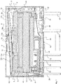
- einen Längsschnitt durch das Relais der ersten Ausführungsform,
- Fig. 3
- eine perspektivische Ansicht eines Trägerbauteils schräg von oben und auf eine Längsseite sowie eine Stirnseite,
- Fig. 4
- eine perspektivische Ansicht einer Spulenbaugruppe,
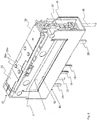
- Fig. 5
- eine Explosionsdarstellung der Einzelteile des Relais der ersten Ausführungsform,
- Fig. 6
- eine zweite Ausführungsform des Relais in perspektivischer Ansicht,
- Fig. 7
- einen Längsschnitt durch das Relais der
Fig. 6 , und - Fig. 8
- eine Explosionsdarstellung der Einzelteile des Relais der
Fig. 6 .
- Fig. 1
- a perspective view of a first embodiment of a relay obliquely from above on a long side and a narrow side with the housing cover removed,
- Fig. 2
- a longitudinal section through the relay of the first embodiment,
- Fig. 3
- a perspective view of a carrier component obliquely from above and on a longitudinal side and an end face,
- Fig. 4
- a perspective view of a coil assembly,
- Fig. 5
- an exploded view of the individual parts of the relay of the first embodiment,
- Fig. 6
- a second embodiment of the relay in perspective view,
- Fig. 7
- a longitudinal section through the relay of the
Fig. 6 , and - Fig. 8
- an exploded view of the individual parts of the relay
Fig. 6 .
Das elektromagnetische Relais ist aus einem Magnetsystem und einem Schaltersystem aufgebaut, die durch Gehäusebauteile zusammengehalten und geschützt werden. Das Magnetsystem umfasst einen Elektromagneten, der aus einer Spulenbaugruppe 10 (
Im dargestellten Ausführungsbeispiel (
Das in
Das stockwerkartige Trägerbauteil 40 ist auch zur Aufnahme der Polbaugruppe, also der Magnetflussteile 7,8, 9 und des Permanentmagneten 11 zuständig. Zu diesem Zweck ist ein in Nischen aufgeteilter, ankerseitiger Aufnahmeraum 41 vorgesehen. Die Teile 7, 8, 9 und 11 werden durch Einbetten im Trägerbauteil 40 befestigt. Es kommen verschiedene Einbettungsverfahren in Betracht, beispielsweise Umspritzen, Einkleben, Einpressen. Auf der Oberseite des Trägerbauteils 40 ist noch ein Festkontakt 21 vorgesehen, der mit einem Anschlussstift 26 in elektrischer Verbindung steht, der im Trägerbauteil 40 ebenfalls durch Einbetten befestigt ist.The
Das Schaltersystem enthält einen Diagnoseschalter 20 und wenigstens einen Lastschalter 30. Der Diagnoseschalter 20 umfasst den Festkontakt 21 und einen beweglichen Kontakt 22, der als Doppelkontakt am gabelförmigen Ende einer Kontaktfeder 23 angebracht ist. Die Kontaktfeder 23 ist am Schenkel 12a des Ankers 12 befestigt und wird von diesem betätigt. Der bewegliche Kontakt 22 stellt die elektrische Verbindung mit dem Anschlussstift 25 her.The switch system contains a
In einer abgewandelten Ausführungsform der Erfindung ist der Prüfkontakt-Anschlussstift 25 in dem Trägerbauteil 40 parallel zum Prüfkontakt-Anschlussstift 26 eingebettet (nicht dargestellt) und es sind zwei voneinander getrennte Festkontakte auf der Oberseite des Trägerbauteils 40 vorgesehen. In dieser Ausführungsform wird das Ende der Kontaktfeder 23 als ein Brückenkontakt zum Schließen des Schalters 20 benutzt.In a modified embodiment of the invention, the test
Der Lastschalter 30 umfasst einen Festkontakt 31 und einen beweglichen Kontakt 32, der auf einer Kontaktfeder 33 sitzt, die über eine Stromschiene 34 an dem Trägerbauteil 40 befestigt ist und darüber hinaus mit einem Lastanschlussstift 35 in elektrischer Verbindung steht. Der Festkontakt 31 steht mit einem weiteren Lastanschlussstift 36 in leitender Verbindung. Die Betätigung der Kontaktfeder 33 erfolgt über ein elektrisch isolierendes Koppelglied 37, dessen oberes Ende mechanisch mit dem zweiten Schenkel 12b des Ankers 12 verbunden ist. Die mechanische Verbindung kann über eine Überhubfeder 38 erfolgen, wie dargestellt, oder aber durch direkte Verbindung der Enden des Wippankers 12 und des Koppelgliedes 37.The
Der Anker 12 besitzt neben seinen beiden Schenkeln 12a und 12b noch ein gebogenes Lagerteil 12c, mit dem der Anker auf dem als Lagerstück gebauten Magnetflussteil 9 aufsitzt. Je nach dem Funktionstyp des Relais (monostabil, bistabil) sind die Schenkel 12a, 12b des Ankers 12 unterschiedlich lang und werden mit unterschiedlichen Polspaltweiten durch Federkräfte gehalten. Solche Federkräfte werden durch die Kontaktfeder 23, die Überhubfeder 38 (falls vorhanden) und die Kontaktfeder 33 erzeugt. Die Kontaktfeder 23 ist am Schenkel 12a des Ankers angenietet und besitzt Federfortsätze 23a und 23b sowie einen Befestigungslappen 23c, der in bestimmter Winkelstellung zwischen Anker 12 und Poloberfläche 7 an dem Lagerstück 9 festgeschweißt ist. Die Überhubfeder 38 ist ähnlich am Schenkel 12b fest genietet und weist ebenfalls Federfortsätze 38a, 38b sowie einen Befestigungslappen 38c auf, der am Lagerstück 9 festgeschweißt ist. Neben der Kraft der Kontaktfeder 33 sind es vor allem die Torsionskräfte der Federschenkel 23b und 38b, die für das Gesamtfederverhalten des Relais verantwortlich sind.In addition to its two
Außer den Federkräften spielt auch die magnetische Anziehungskraft auf den Anker 12 eine Rolle, ob ein monostabiles oder ein bistabiles Relais erhalten wird. Für die Anziehungskräfte auf die Schenkel 12a, 12b des Ankers spielen die Stärke des Permanentmagneten 11 und die Größen der Polflächen der Polstücke 7, 8 eine Rolle. Wenn die magnetische Anziehungskraft in einer Endstellung des Ankers größer als die in Abheberichtung wirksame Federkraft und in der anderen Endstellung die magnetische Anziehungskraft kleiner als die Abhebekraft der Federn ist, dann liegt ein monostabiles Relais vor. Wenn dagegen die magnetische Anziehungskraft in beiden Endstellungen des Ankers größer als die in Abheberichtung wirksame Federkraft ist, liegt ein bistabiles Relais vor.In addition to the spring forces, the magnetic force of attraction on the
Während das Trägerbauteil 40 das Hauptelement des Gehäuses darstellt, gibt es noch einen Gehäuseboden 50 und eine Gehäusehaube 60. Wie in
Auf der Oberseite der Gehäusehaube 60 kann sich ein Schalter befinden, um die Stellung des Ankers 12 von Hand zu verändern.A switch can be located on the top of the
Mit den
Bei der zweiten Ausführungsform des Relais ist der Permanentmagnet 11 aus zwei Teilstücken 11a und 11b und mit einem dazwischen gefügten Magnetflussteil 9 aus Weicheisen ausgeführt und bildet einen dreipoligen Permanentmagneten. Das Teilstück 11a weist die stärkere Koerzitivkraft gegenüber dem Teilstück 11b auf. Die beiden Teilstücke 11a und 11b weisen zum Magnetflussteil 9 hin die gleiche Polarität auf, also entweder sind beide dort als Südpol oder als Nordpol ausgebildet, während zu den äußeren Enden des Relais hin dann der insgesamt dreipolige Permanentmagnet 11 Nordpole oder eben Südpole zeigt. Das Magnetflussteil 9 vermittelt die angrenzende Polarität, beispielsweise Südpol, wenn der Permanentmagnet nach außen Nordpol zeigt, und Nordpol, wenn der Permanentmagnet nach außen Südpol zeigt.In the second embodiment of the relay, the
Bei der zweiten Ausführungsform ist die Lagerung des Ankers 12 gegenüber der ersten Ausführungsform abgewandelt, indem eine Kreuzfeder 39 die Lagerung des Ankers 12 auf dem Magnetflussteil 9 übernimmt. Die Kreuzfeder 39 weist Lappen 39a auf, mit denen sie auf dem Magnetflussteil 9 durch Schweißen verbunden ist, ferner einen Torsionssteg 39b und quer dazu einen Stützlappen 39c zur Abstützung des Ankers 12. An der Kreuzfeder 39 kann noch ein weiterer Lappen 39d angesetzt sein, der zur Dämpfung des Aufschlagens des Ankers 12 auf dem Magnetflussteil 8 dient und gleichzeitig dabei gespannt wird, was beim späteren Umschalten des Ankers 12 nützlich ist, da sich der Anker dann leichter vom Magnetflussteil 8 löst. Die Kreuzfeder 39 wirkt als Torsionsfeder, d. h. es gibt keine Lagerreibung und die Hystereseverluste der Feder 39 sind sehr klein.In the second embodiment, the mounting of the
Als weitere Variante weist die zweite Ausführungsform eine einstückige Ausbildung von Kontaktfeder 23 und Überhubfeder 38 auf. Die Kontaktfeder 23 ist elektrisch leitend und mit dem elektrisch leitenden Anker 12 verbunden, der wiederum über die elektrisch leitende Kreuzfeder 39 mit dem elektrisch leitenden Magnetflussteil 9 verbunden ist, das wiederum in elektrisch leitender Verbindung mit dem Prüfkontaktanschlussstift 25 steht.As a further variant, the second embodiment has a one-piece design of
Zur Anpassung der Haftkraft des Ankers 12 beim Schenkel 12b an dem Magnetflussteil 8 ist noch ein Zwischenstück 8a aus Blech oder Kunststoff vorgesehen. Wegen der unterschiedlichen Längen der Schenkel 12a, 12b des Ankers 12 sind nämlich die dort ausgeübten Abhebekräfte unterschiedlich, was durch die Zwischenlage des Teils 8a etwas ausgeglichen wird.An
Das gepolte elektromagnetische Relais wird in neuartiger Art und Weise hergestellt und zusammengesetzt. Die in
Die in den
Es stellt eine Besonderheit bei der Erfindung dar, dass bei der Montage der Polbaugruppe nicht ein fertiger Permanentmagnet montiert wird, sondern ein Permanentmagnet-Vorläufer aus unmagnetisierter, ferromagnetischer Legierung mit Anteil von seltenen Erden. Solche Vorläufer-Magnete können mit außerordentlich hohen Koerzitivkräften "aufmagnetisiert" werden. Zu diesem Zweck muss ein sehr starkes Magnetfeld angelegt werden, das den Vorläufer-Magneten in gewünschter Richtung magnetisiert. Praktisch muss man eine Spule um die Polbaugruppe legen, um die benötigte Feldstärke zu erzeugen. Man kann dies im eingebauten Zustand der Polbaugruppe in dem Aufnahmeraum 41 des Trägerbauteils 40 bewerkstelligen. Zu beachten ist, dass der Aufnahmeraum 42 für die Spulenbaugruppe 10 leer bleiben kann. Dadurch wird vermieden, dass sich eine hohe Spannung mit einem starken elektrischen Strom in der Spulenbaugruppe entwickelt, was zu deren Beschädigung führen könnte.It is a special feature of the invention that when assembling the pole assembly, not a finished permanent magnet is assembled, but a permanent magnet precursor made of non-magnetized, ferromagnetic alloy with a proportion of rare earths. Such precursor magnets can be "magnetized" with extremely high coercive forces. For this purpose, a very strong magnetic field must be applied, which magnetizes the precursor magnet in the desired direction. Practically you have to put a coil around the pole assembly to generate the required field strength. This can be done in the installed state of the pole assembly in the receiving
Bei der Aufmagnetisierung der Polbaugruppe ist auf die Art des zu erzeugenden Permanentmagneten Rücksicht zu nehmen. Wenn ein einstückiger zweipoliger Permanentmagnet zu erzeugen ist, was der ersten Ausführungsform des Relais entspricht, genügt die beschriebenen Vorgehensweise. Wenn dagegen ein dreipoliger Permanentmagnet durch Aufmagnetisierung erzeugt werden soll, geht man in abgewandelter Weise vor. Man benutzt zwei Vorläufer-Magnet-Teilstücke 11a, 11b zu beiden Seiten des mittleren Magnetflussteils 9 und in Berührung zu den benachbarten Magnetflussteilen 7 bzw. 8. Eines dieser Vorläufer-Magnet-Teilstücke, hier das Teilstück 11a, besteht aus einer stärker aufmagnetisierbaren Legierung gegenüber dem anderen Teilstück 11b. Das stärker aufmagnetisierbare Teilstück 11a kann auch kleiner gemacht werden, als das schwächer aufmagnetisierbare Teilstück 11b. Nach Montage der Polbaugruppe etwa in der Reihenfolge der Teile 7, 11a, 9, 11b und 8 in dem Aufnahmeraum 41 des Trägerbauteils 40 wird eine Magnetisierung in einer bestimmten Richtung vorgenommen, wie sie dem stärkeren Teil-Permanentmagnet 11a entspricht. Alsdann wird ein der ursprünglichen Magnetrichtung entgegen gesetztes, jedoch schwächeres Magnetfeld an die Polbaugruppe angelegt, wobei dieses schwächere Magnetfeld nicht ausreicht, den Teil-Permanentmagnet 11a umzumagnetisieren, jedoch ausreichend ist, den schwächeren Teil-Permanentmagnet 11b umzumagnetisieren. Dies hat zur Folge, dass sich an dem mittleren Magnetflussteil 9 gleichnamige Pole gegenüberstehen. Auf diese Weise erhält man einen Gesamt-Permanentmagnet 11 mit zwei gleichnamigen Polen an der Außenseite, also zu den als Polstücke wirksamen Magnetflussteilen 7 und 8, und einen entgegen gesetzten Pol am mittleren Magnetflussteil 9. Diese Struktur bildet einen dreipoligen Permanentmagneten.When magnetizing the pole assembly, the type of permanent magnet to be generated must be taken into account. If a one-piece two-pole permanent magnet is to be produced, which corresponds to the first embodiment of the relay, the procedure described is sufficient. If, on the other hand, a three-pole permanent magnet is to be generated by magnetization, the procedure is modified. Two
Nach der Herstellung des Permanentmagneten 11 kann die Spulenbaugruppe 10 ungefährdet in den schubfachartigen Aufnahmeraum 42 montiert werden.After the
Es werden nunmehr die sonstigen Einzelteile zur Komplettierung des Relais montiert. Dazu gehören der Anker 12 mit seinen Federn 23, 38 bzw. 39, der Lastschalter 30 zusammen mit dem Koppelglied 37 und die Gehäuseteile 50 und 60.The other items to complete the relay are now assembled. These include the
Mit dem neuen Relais können viele Funktionalitäten eines gepolten Relais verwirklicht werden, indem die Größe, die Anordnung und die Parameter von einzelnen Bauteilen modifiziert werden. Es können starke Permanentmagnete verwendet werden, ohne dass es zu Komplikationen bei der Montage des Relais kommt, indem der Permanentmagnet durch Aufmagnetisierung in dem Trägerbauteil gewonnen wird, da dieses zum Zeitpunkt der Aufmagnetisierung keine gefährdeten Bauteile, wie etwa die Magnetspule, enthält.With the new relay, many functionalities of a polarized relay can be implemented by modifying the size, the arrangement and the parameters of individual components. Strong permanent magnets can be used without complications in the assembly of the relay, in that the permanent magnet is obtained by magnetization in the carrier component, since this does not contain any endangered components, such as the magnet coil, at the time of magnetization.
Die Relais können sehr klein gebaut werden, da man Permanentmagnete mit großer Koerzitivkraft erzeugen kann.The relays can be made very small, since permanent magnets with a large coercive force can be generated.
Claims (12)
- A method for producing a polarized electromagnetic relay comprising an electromagnet, a permanent magnet (11), an armature (12), and an actuable switch (20, 30), comprising the steps of:a) providing a coil assembly (10) comprising a coil (1) with a core (2) and pole pieces (3, 4) as a structural unit;b) providing a support component (40) that has a first accommodation space (41) for a pole assembly (7, 8, 9, 11) extending to the side of the armature, and a second accommodation space (42) for the coil assembly (10), the second accommodation space being arranged in the manner of a shelf compartment;c) mounting the pole assembly (7, 8, 9, 11) including magnetic flux pieces (7, 8, 9) and an unmagnetized permanent magnet precursor in the first accommodation space (41);d) magnetizing the permanent magnet precursor in the pole assembly while the second accommodation space (42) is empty, to obtain the permanent magnet (11);e) mounting the coil assembly (10) in the second accommodation space (42);f) mounting the rest of the relay components to complete the relay.
- The method as claimed in claim 1, for providing a three-pole permanent magnet (11);
wherein step c) comprises mounting two precursor magnet portions (11a, 11b) which are magnetizable to a different extent, between three magnetic flux pieces (7, 8, 9) of the pole assembly (7, 8, 9, 11); and wherein step d) comprises the sub-steps of:d1) magnetizing the two precursor magnet portions (11a, 11b);d2) remagnetizing the weaker precursor magnet portion (11b) in such a manner that like poles of the magnetized portions (11a, 11b) face each other at the magnetic flux piece (9) separating them. - A polarized electromagnetic relay, produced according to any one of claims 1 or 2, comprising:- a support component (40) of a shelf-like or storey-like configuration, having a first accommodation space (41) extending to the side of the armature, a second accommodation space (42) arranged in the manner of a shelf compartment, and a third accommodation space (45) extending to the side of a load contact, the first, second and third accommodation spaces being arranged one upon the other;- a pole assembly (7, 8, 9, 11) comprising magnetic flux pieces (7, 8, 9) defining a central magnetic flux piece (9) and pole pieces (7, 8) on either side thereof, and a permanent magnet (11) between at least one of the pole pieces and the central magnetic flux piece (9), the pole assembly (7, 8, 9, 11) being accommodated in the first accommodation space (41) of the support component (40);- a coil assembly (10) comprising a coil (1) with a core (2) and pole pieces (3, 4) as a structural unit and forming part of an electromagnet, which is accommodated in the second accommodation space (42);- an armature (12) which is arranged on the pole assembly (7, 8, 9, 11) and is pivotable relative thereto, and which is connected to movable switch elements (23, 33).
- The relay as claimed in claim 3, wherein the third accommodation space (45) of the support component (40) accommodates a load switch (30) and is closed by a housing bottom (50).
- The relay as claimed in claim 4, wherein the housing bottom (50) supports at least one fixed contact (31) of the load switch (30), and together with the support component (40) supports terminal pins (15, 16, 25, 26, 35, 36).
- The relay as claimed in any one of claims 3 to 5,- wherein the electromagnet comprises a U-shaped yoke (2, 3, 4) with adjacent magnetic flux pieces (7, 8) that define pole pieces;- wherein the armature (12) is configured as a rocking armature having a first and a second leg (12a, 12b), the armature being supported on a central magnetic flux piece (9) and forming a closed low magnetic gap magnetic flux path, by a respective one of its legs (12a, 12b) together with the central magnetic flux piece (9) and a respective one of the magnetic flux pieces (7, 8) operative as pole pieces; and- wherein each of the legs (12a, 12b) actuates a movable contact (22, 32) of a respective switch (20, 30) .
- The relay as claimed in claim 6, wherein a first switch which is usable as a diagnostic switch (20) is formed by a fixed contact (21) on the support component (40) and a movable contact (22) at a first contact spring (23) which is fixed on the first leg (12a) of the rocking armature (12), and wherein a second switch which is usable as a load switch (30) is formed by a fixed contact (31) on the housing bottom (50) and a movable contact (32) at a second contact spring (33) which is mechanically coupled to the second leg (12b) of the rocking armature (12) through an electrically insulating coupling member (37).
- The relay as claimed in claim 7, wherein the support component (40) has a guideway (46) for the insulating coupling member (37), and wherein a housing cap (60) encloses the support component (40) thereby partially encompassing the housing bottom (50).
- The relay as claimed in any one of claims 3 to 8, wherein the permanent magnet (11) is a one-piece component, one pole thereof adjoining the central magnetic flux piece (9) and the other pole thereof adjoining one of the magnetic flux pieces (7, 8) that are effective as magnetic poles.
- The relay as claimed in any one of claims 3 to 8, wherein the permanent magnet (11) comprises two portions (11a, 11b) which are facing each other with like poles at the central magnetic flux piece (9) so as to form an three-pole permanent magnet (11) as a whole.
- The relay as claimed in claim 10, wherein one of the portions (11a) has a higher coercive force than the other portion (11b).
- The relay as claimed in claim 11, wherein the portion (11a) with the higher coercive force occupies a smaller volume than the portion (11b) with the lower coercive force.
Applications Claiming Priority (2)
| Application Number | Priority Date | Filing Date | Title |
|---|---|---|---|
| DE102012006436.5A DE102012006436B4 (en) | 2012-03-30 | 2012-03-30 | Poled electromagnetic relay and process for its manufacture |
| PCT/EP2013/056547 WO2013144218A2 (en) | 2012-03-30 | 2013-03-27 | Polarized electromagnetic relay and method for production thereof |
Publications (2)
| Publication Number | Publication Date |
|---|---|
| EP2831900A2 EP2831900A2 (en) | 2015-02-04 |
| EP2831900B1 true EP2831900B1 (en) | 2021-04-28 |
Family
ID=48044776
Family Applications (1)
| Application Number | Title | Priority Date | Filing Date |
|---|---|---|---|
| EP13713418.5A Active EP2831900B1 (en) | 2012-03-30 | 2013-03-27 | Polarized electromagnetic relay and method for production thereof |
Country Status (6)
| Country | Link |
|---|---|
| US (1) | US9368304B2 (en) |
| EP (1) | EP2831900B1 (en) |
| JP (1) | JP5989225B2 (en) |
| CN (1) | CN104170047B (en) |
| DE (1) | DE102012006436B4 (en) |
| WO (1) | WO2013144218A2 (en) |
Families Citing this family (11)
| Publication number | Priority date | Publication date | Assignee | Title |
|---|---|---|---|---|
| USD770387S1 (en) * | 2014-03-19 | 2016-11-01 | Phoenix Contact Gmbh & Co. Kg | Electrical connector |
| JP6422249B2 (en) * | 2014-07-03 | 2018-11-14 | 富士通コンポーネント株式会社 | Electromagnetic relay |
| JP6258138B2 (en) * | 2014-07-03 | 2018-01-10 | 富士通コンポーネント株式会社 | Electromagnetic relay |
| CN106716587B (en) * | 2014-07-23 | 2018-12-11 | 富士通电子零件有限公司 | Electromagnetic relay |
| JP6433706B2 (en) | 2014-07-28 | 2018-12-05 | 富士通コンポーネント株式会社 | Electromagnetic relay and coil terminal |
| DE102016101501B4 (en) | 2016-01-28 | 2018-12-27 | Phoenix Contact Gmbh & Co. Kg | Electromechanical relay and device for detecting the switching state of an electromechanical relay |
| DE102016112663B4 (en) * | 2016-07-11 | 2018-04-12 | Phoenix Contact Gmbh & Co. Kg | Electromechanical relay, terminal block and electromechanical relay module |
| DE102016125382A1 (en) * | 2016-12-22 | 2018-06-28 | Phoenix Contact Gmbh & Co. Kg | Modular contactor arrangement |
| BE1025465B1 (en) * | 2017-08-11 | 2019-03-11 | Phoenix Contact Gmbh & Co. Kg | Method for magnetizing at least two magnets of different magnetic coercive field strengths |
| JP7135567B2 (en) * | 2018-08-10 | 2022-09-13 | オムロン株式会社 | relay |
| CN110335788A (en) * | 2019-07-09 | 2019-10-15 | 厦门宏发电声股份有限公司 | A kind of miniaturization power magnetic force keeping relay |
Family Cites Families (21)
| Publication number | Priority date | Publication date | Assignee | Title |
|---|---|---|---|---|
| BE560797A (en) * | 1956-09-14 | |||
| DE1614713B1 (en) * | 1967-11-08 | 1971-03-04 | Schaltbau Gmbh | Latching relay |
| DD120156A1 (en) | 1975-06-23 | 1976-06-05 | ||
| DE2614942A1 (en) * | 1976-04-07 | 1977-10-20 | Ernst Duerr | ELECTROMAGNETIC SMALL SWITCHING RELAY |
| US4286244A (en) * | 1980-02-29 | 1981-08-25 | Leach Corporation | Electromagnetic actuator for a latch relay |
| JPS5760633A (en) * | 1980-09-26 | 1982-04-12 | Fujitsu Ltd | Solenoid relay |
| US4912438A (en) | 1987-10-22 | 1990-03-27 | Nec Corporation | Electromagnetic relay |
| DE3802688C2 (en) | 1988-01-29 | 1997-04-10 | Siemens Ag | Polarized relay |
| DE58905723D1 (en) | 1988-03-25 | 1993-11-04 | Siemens Ag | POLARIZED MULTICONTACT ELECTROMAGNETIC RELAY. |
| US4975666A (en) * | 1989-03-28 | 1990-12-04 | Matsushita Electric Works, Ltd. | Polarized electromagnetic relay |
| JPH04149924A (en) | 1990-10-15 | 1992-05-22 | Nec Corp | Electromagnetic relay |
| DE59303588D1 (en) | 1992-05-15 | 1996-10-02 | Siemens Ag | POLARIZED POWER RELAY |
| JP3319814B2 (en) | 1993-05-26 | 2002-09-03 | 松下電工株式会社 | High frequency relay |
| DE19520220C1 (en) * | 1995-06-01 | 1996-11-21 | Siemens Ag | Polarized electromagnetic relay |
| US5805039A (en) * | 1995-08-07 | 1998-09-08 | Siemens Electromechanical Components, Inc. | Polarized electromagnetic relay |
| DE19719355C1 (en) | 1997-05-07 | 1998-11-05 | Siemens Ag | Polarised electromagnetic relay |
| WO2000007199A2 (en) * | 1998-07-30 | 2000-02-10 | Siemens Electromechanical Components Gmbh & Co. Kg | Electromagnetic relay and method for producing the same |
| WO2000007200A2 (en) * | 1998-07-30 | 2000-02-10 | Siemens Electromechanical Components Gmbh & Co. Kg | Electromagnetic relay |
| DE10084279B3 (en) | 1999-12-24 | 2013-04-25 | Takamisawa Electric Co. Ltd. | Method for producing an exchange relay |
| CN2829067Y (en) * | 2005-06-09 | 2006-10-18 | 厦门宏发电声有限公司 | Polar relay with high sensitivity double working gap |
| CN201655689U (en) * | 2010-06-04 | 2010-11-24 | 北京松下控制装置有限公司 | Yoke iron for polarizing electromagnetic relay and polarization electromagnetic relay |
-
2012
- 2012-03-30 DE DE102012006436.5A patent/DE102012006436B4/en active Active
-
2013
- 2013-03-27 EP EP13713418.5A patent/EP2831900B1/en active Active
- 2013-03-27 US US14/388,104 patent/US9368304B2/en active Active
- 2013-03-27 CN CN201380015376.3A patent/CN104170047B/en active Active
- 2013-03-27 JP JP2015502328A patent/JP5989225B2/en active Active
- 2013-03-27 WO PCT/EP2013/056547 patent/WO2013144218A2/en active Application Filing
Non-Patent Citations (1)
| Title |
|---|
| None * |
Also Published As
| Publication number | Publication date |
|---|---|
| JP2015515097A (en) | 2015-05-21 |
| US20150048909A1 (en) | 2015-02-19 |
| CN104170047B (en) | 2017-04-05 |
| CN104170047A (en) | 2014-11-26 |
| DE102012006436B4 (en) | 2020-01-30 |
| JP5989225B2 (en) | 2016-09-07 |
| DE102012006436A1 (en) | 2013-10-02 |
| EP2831900A2 (en) | 2015-02-04 |
| WO2013144218A3 (en) | 2013-12-12 |
| WO2013144218A2 (en) | 2013-10-03 |
| US9368304B2 (en) | 2016-06-14 |
Similar Documents
| Publication | Publication Date | Title |
|---|---|---|
| EP2831900B1 (en) | Polarized electromagnetic relay and method for production thereof | |
| EP2831901B1 (en) | Relay having two switches that can be actuated in opposite directions | |
| EP1032941B1 (en) | Miniaturised flat spool relay | |
| DE19820821C1 (en) | Electromagnetic relay with a rocker anchor | |
| DE3885508T2 (en) | Electromagnetic relay. | |
| DE3303665A1 (en) | POLARIZED ELECTROMAGNETIC RELAY | |
| DE69114865T2 (en) | Electromagnetic relay. | |
| DE3586200T2 (en) | ELECTROMAGNETIC RELAY. | |
| DE4243607A1 (en) | Polarised electromechanical relay - has pivot mounted armature block mounted on main coil block with leaf spring contact carriers attached | |
| DE69019866T2 (en) | Polarized electromagnetic relay. | |
| DE2749468A1 (en) | ELECTROMAGNETIC RELAY | |
| EP2645386B1 (en) | Relay with improved insulating properties | |
| EP0072976B1 (en) | Polarised electromagnetic relay | |
| DE102012106330B4 (en) | Spool core for electromagnetic drive and selbiger and method for its production | |
| DE3222336C2 (en) | ||
| DE3124412C1 (en) | Small polarized electromagnetic relay | |
| DE69709786T2 (en) | POLARIZED RELAY WITH FIXING DEVICE FOR THE PERMANENT MAGNET | |
| DE3802688C2 (en) | Polarized relay | |
| EP2645398B1 (en) | Relay with improved insulating properties | |
| DE2905686A1 (en) | Miniature relay for short changeover times - has shaped projection on coil forming to house spaced magnetic inserts and pole shoes | |
| EP0373109B1 (en) | Polarised printed-circuit board relay | |
| DE3408504C2 (en) | ||
| DE102016107410A1 (en) | Bistable actuator for a polarized electromagnetic relay | |
| EP0630516B1 (en) | Polarized electromagnetic relay | |
| EP1135786B1 (en) | Electromagnetic small relay |
Legal Events
| Date | Code | Title | Description |
|---|---|---|---|
| PUAI | Public reference made under article 153(3) epc to a published international application that has entered the european phase |
Free format text: ORIGINAL CODE: 0009012 |
|
| 17P | Request for examination filed |
Effective date: 20141030 |
|
| AK | Designated contracting states |
Kind code of ref document: A2 Designated state(s): AL AT BE BG CH CY CZ DE DK EE ES FI FR GB GR HR HU IE IS IT LI LT LU LV MC MK MT NL NO PL PT RO RS SE SI SK SM TR |
|
| AX | Request for extension of the european patent |
Extension state: BA ME |
|
| DAX | Request for extension of the european patent (deleted) | ||
| 17Q | First examination report despatched |
Effective date: 20151124 |
|
| STAA | Information on the status of an ep patent application or granted ep patent |
Free format text: STATUS: EXAMINATION IS IN PROGRESS |
|
| GRAP | Despatch of communication of intention to grant a patent |
Free format text: ORIGINAL CODE: EPIDOSNIGR1 |
|
| STAA | Information on the status of an ep patent application or granted ep patent |
Free format text: STATUS: GRANT OF PATENT IS INTENDED |
|
| INTG | Intention to grant announced |
Effective date: 20171030 |
|
| GRAJ | Information related to disapproval of communication of intention to grant by the applicant or resumption of examination proceedings by the epo deleted |
Free format text: ORIGINAL CODE: EPIDOSDIGR1 |
|
| STAA | Information on the status of an ep patent application or granted ep patent |
Free format text: STATUS: EXAMINATION IS IN PROGRESS |
|
| INTC | Intention to grant announced (deleted) | ||
| GRAP | Despatch of communication of intention to grant a patent |
Free format text: ORIGINAL CODE: EPIDOSNIGR1 |
|
| STAA | Information on the status of an ep patent application or granted ep patent |
Free format text: STATUS: GRANT OF PATENT IS INTENDED |
|
| INTG | Intention to grant announced |
Effective date: 20201202 |
|
| GRAS | Grant fee paid |
Free format text: ORIGINAL CODE: EPIDOSNIGR3 |
|
| GRAA | (expected) grant |
Free format text: ORIGINAL CODE: 0009210 |
|
| STAA | Information on the status of an ep patent application or granted ep patent |
Free format text: STATUS: THE PATENT HAS BEEN GRANTED |
|
| AK | Designated contracting states |
Kind code of ref document: B1 Designated state(s): AL AT BE BG CH CY CZ DE DK EE ES FI FR GB GR HR HU IE IS IT LI LT LU LV MC MK MT NL NO PL PT RO RS SE SI SK SM TR |
|
| REG | Reference to a national code |
Ref country code: GB Ref legal event code: FG4D Free format text: NOT ENGLISH |
|
| REG | Reference to a national code |
Ref country code: CH Ref legal event code: EP |
|
| REG | Reference to a national code |
Ref country code: DE Ref legal event code: R096 Ref document number: 502013015679 Country of ref document: DE |
|
| REG | Reference to a national code |
Ref country code: AT Ref legal event code: REF Ref document number: 1388035 Country of ref document: AT Kind code of ref document: T Effective date: 20210515 |
|
| REG | Reference to a national code |
Ref country code: IE Ref legal event code: FG4D Free format text: LANGUAGE OF EP DOCUMENT: GERMAN |
|
| REG | Reference to a national code |
Ref country code: LT Ref legal event code: MG9D |
|
| PG25 | Lapsed in a contracting state [announced via postgrant information from national office to epo] |
Ref country code: FI Free format text: LAPSE BECAUSE OF FAILURE TO SUBMIT A TRANSLATION OF THE DESCRIPTION OR TO PAY THE FEE WITHIN THE PRESCRIBED TIME-LIMIT Effective date: 20210428 Ref country code: NL Free format text: LAPSE BECAUSE OF FAILURE TO SUBMIT A TRANSLATION OF THE DESCRIPTION OR TO PAY THE FEE WITHIN THE PRESCRIBED TIME-LIMIT Effective date: 20210428 Ref country code: LT Free format text: LAPSE BECAUSE OF FAILURE TO SUBMIT A TRANSLATION OF THE DESCRIPTION OR TO PAY THE FEE WITHIN THE PRESCRIBED TIME-LIMIT Effective date: 20210428 Ref country code: BG Free format text: LAPSE BECAUSE OF FAILURE TO SUBMIT A TRANSLATION OF THE DESCRIPTION OR TO PAY THE FEE WITHIN THE PRESCRIBED TIME-LIMIT Effective date: 20210728 Ref country code: HR Free format text: LAPSE BECAUSE OF FAILURE TO SUBMIT A TRANSLATION OF THE DESCRIPTION OR TO PAY THE FEE WITHIN THE PRESCRIBED TIME-LIMIT Effective date: 20210428 |
|
| PG25 | Lapsed in a contracting state [announced via postgrant information from national office to epo] |
Ref country code: IS Free format text: LAPSE BECAUSE OF FAILURE TO SUBMIT A TRANSLATION OF THE DESCRIPTION OR TO PAY THE FEE WITHIN THE PRESCRIBED TIME-LIMIT Effective date: 20210828 Ref country code: GR Free format text: LAPSE BECAUSE OF FAILURE TO SUBMIT A TRANSLATION OF THE DESCRIPTION OR TO PAY THE FEE WITHIN THE PRESCRIBED TIME-LIMIT Effective date: 20210729 Ref country code: LV Free format text: LAPSE BECAUSE OF FAILURE TO SUBMIT A TRANSLATION OF THE DESCRIPTION OR TO PAY THE FEE WITHIN THE PRESCRIBED TIME-LIMIT Effective date: 20210428 Ref country code: RS Free format text: LAPSE BECAUSE OF FAILURE TO SUBMIT A TRANSLATION OF THE DESCRIPTION OR TO PAY THE FEE WITHIN THE PRESCRIBED TIME-LIMIT Effective date: 20210428 Ref country code: SE Free format text: LAPSE BECAUSE OF FAILURE TO SUBMIT A TRANSLATION OF THE DESCRIPTION OR TO PAY THE FEE WITHIN THE PRESCRIBED TIME-LIMIT Effective date: 20210428 Ref country code: PL Free format text: LAPSE BECAUSE OF FAILURE TO SUBMIT A TRANSLATION OF THE DESCRIPTION OR TO PAY THE FEE WITHIN THE PRESCRIBED TIME-LIMIT Effective date: 20210428 Ref country code: PT Free format text: LAPSE BECAUSE OF FAILURE TO SUBMIT A TRANSLATION OF THE DESCRIPTION OR TO PAY THE FEE WITHIN THE PRESCRIBED TIME-LIMIT Effective date: 20210830 Ref country code: NO Free format text: LAPSE BECAUSE OF FAILURE TO SUBMIT A TRANSLATION OF THE DESCRIPTION OR TO PAY THE FEE WITHIN THE PRESCRIBED TIME-LIMIT Effective date: 20210728 Ref country code: ES Free format text: LAPSE BECAUSE OF FAILURE TO SUBMIT A TRANSLATION OF THE DESCRIPTION OR TO PAY THE FEE WITHIN THE PRESCRIBED TIME-LIMIT Effective date: 20210428 |
|
| REG | Reference to a national code |
Ref country code: NL Ref legal event code: MP Effective date: 20210428 |
|
| PG25 | Lapsed in a contracting state [announced via postgrant information from national office to epo] |
Ref country code: EE Free format text: LAPSE BECAUSE OF FAILURE TO SUBMIT A TRANSLATION OF THE DESCRIPTION OR TO PAY THE FEE WITHIN THE PRESCRIBED TIME-LIMIT Effective date: 20210428 Ref country code: CZ Free format text: LAPSE BECAUSE OF FAILURE TO SUBMIT A TRANSLATION OF THE DESCRIPTION OR TO PAY THE FEE WITHIN THE PRESCRIBED TIME-LIMIT Effective date: 20210428 Ref country code: DK Free format text: LAPSE BECAUSE OF FAILURE TO SUBMIT A TRANSLATION OF THE DESCRIPTION OR TO PAY THE FEE WITHIN THE PRESCRIBED TIME-LIMIT Effective date: 20210428 Ref country code: SM Free format text: LAPSE BECAUSE OF FAILURE TO SUBMIT A TRANSLATION OF THE DESCRIPTION OR TO PAY THE FEE WITHIN THE PRESCRIBED TIME-LIMIT Effective date: 20210428 Ref country code: SK Free format text: LAPSE BECAUSE OF FAILURE TO SUBMIT A TRANSLATION OF THE DESCRIPTION OR TO PAY THE FEE WITHIN THE PRESCRIBED TIME-LIMIT Effective date: 20210428 Ref country code: RO Free format text: LAPSE BECAUSE OF FAILURE TO SUBMIT A TRANSLATION OF THE DESCRIPTION OR TO PAY THE FEE WITHIN THE PRESCRIBED TIME-LIMIT Effective date: 20210428 |
|
| REG | Reference to a national code |
Ref country code: DE Ref legal event code: R097 Ref document number: 502013015679 Country of ref document: DE |
|
| PLBE | No opposition filed within time limit |
Free format text: ORIGINAL CODE: 0009261 |
|
| STAA | Information on the status of an ep patent application or granted ep patent |
Free format text: STATUS: NO OPPOSITION FILED WITHIN TIME LIMIT |
|
| 26N | No opposition filed |
Effective date: 20220131 |
|
| PG25 | Lapsed in a contracting state [announced via postgrant information from national office to epo] |
Ref country code: IS Free format text: LAPSE BECAUSE OF FAILURE TO SUBMIT A TRANSLATION OF THE DESCRIPTION OR TO PAY THE FEE WITHIN THE PRESCRIBED TIME-LIMIT Effective date: 20210828 Ref country code: AL Free format text: LAPSE BECAUSE OF FAILURE TO SUBMIT A TRANSLATION OF THE DESCRIPTION OR TO PAY THE FEE WITHIN THE PRESCRIBED TIME-LIMIT Effective date: 20210428 |
|
| PG25 | Lapsed in a contracting state [announced via postgrant information from national office to epo] |
Ref country code: MC Free format text: LAPSE BECAUSE OF FAILURE TO SUBMIT A TRANSLATION OF THE DESCRIPTION OR TO PAY THE FEE WITHIN THE PRESCRIBED TIME-LIMIT Effective date: 20210428 |
|
| REG | Reference to a national code |
Ref country code: BE Ref legal event code: MM Effective date: 20220331 |
|
| PG25 | Lapsed in a contracting state [announced via postgrant information from national office to epo] |
Ref country code: LU Free format text: LAPSE BECAUSE OF NON-PAYMENT OF DUE FEES Effective date: 20220327 Ref country code: IE Free format text: LAPSE BECAUSE OF NON-PAYMENT OF DUE FEES Effective date: 20220327 |
|
| PG25 | Lapsed in a contracting state [announced via postgrant information from national office to epo] |
Ref country code: BE Free format text: LAPSE BECAUSE OF NON-PAYMENT OF DUE FEES Effective date: 20220331 |
|
| P01 | Opt-out of the competence of the unified patent court (upc) registered |
Effective date: 20230424 |
|
| PG25 | Lapsed in a contracting state [announced via postgrant information from national office to epo] |
Ref country code: HU Free format text: LAPSE BECAUSE OF FAILURE TO SUBMIT A TRANSLATION OF THE DESCRIPTION OR TO PAY THE FEE WITHIN THE PRESCRIBED TIME-LIMIT; INVALID AB INITIO Effective date: 20130327 |
|
| PGFP | Annual fee paid to national office [announced via postgrant information from national office to epo] |
Ref country code: AT Payment date: 20240319 Year of fee payment: 12 |
|
| PG25 | Lapsed in a contracting state [announced via postgrant information from national office to epo] |
Ref country code: MK Free format text: LAPSE BECAUSE OF FAILURE TO SUBMIT A TRANSLATION OF THE DESCRIPTION OR TO PAY THE FEE WITHIN THE PRESCRIBED TIME-LIMIT Effective date: 20210428 Ref country code: CY Free format text: LAPSE BECAUSE OF FAILURE TO SUBMIT A TRANSLATION OF THE DESCRIPTION OR TO PAY THE FEE WITHIN THE PRESCRIBED TIME-LIMIT Effective date: 20210428 |
|
| PGFP | Annual fee paid to national office [announced via postgrant information from national office to epo] |
Ref country code: GB Payment date: 20240319 Year of fee payment: 12 |
|
| PGFP | Annual fee paid to national office [announced via postgrant information from national office to epo] |
Ref country code: IT Payment date: 20240321 Year of fee payment: 12 Ref country code: FR Payment date: 20240326 Year of fee payment: 12 |
|
| PGFP | Annual fee paid to national office [announced via postgrant information from national office to epo] |
Ref country code: DE Payment date: 20240529 Year of fee payment: 12 |
|
| PGFP | Annual fee paid to national office [announced via postgrant information from national office to epo] |
Ref country code: CH Payment date: 20240401 Year of fee payment: 12 |