EP2829503B2 - Operating element for an industrial truck - Google Patents
Operating element for an industrial truck Download PDFInfo
- Publication number
- EP2829503B2 EP2829503B2 EP14177269.9A EP14177269A EP2829503B2 EP 2829503 B2 EP2829503 B2 EP 2829503B2 EP 14177269 A EP14177269 A EP 14177269A EP 2829503 B2 EP2829503 B2 EP 2829503B2
- Authority
- EP
- European Patent Office
- Prior art keywords
- control
- levers
- switch
- control levers
- hand
- Prior art date
- Legal status (The legal status is an assumption and is not a legal conclusion. Google has not performed a legal analysis and makes no representation as to the accuracy of the status listed.)
- Active
Links
Images
Classifications
-
- G—PHYSICS
- G05—CONTROLLING; REGULATING
- G05G—CONTROL DEVICES OR SYSTEMS INSOFAR AS CHARACTERISED BY MECHANICAL FEATURES ONLY
- G05G11/00—Manually-actuated control mechanisms provided with two or more controlling members co-operating with one single controlled member
-
- B—PERFORMING OPERATIONS; TRANSPORTING
- B66—HOISTING; LIFTING; HAULING
- B66F—HOISTING, LIFTING, HAULING OR PUSHING, NOT OTHERWISE PROVIDED FOR, e.g. DEVICES WHICH APPLY A LIFTING OR PUSHING FORCE DIRECTLY TO THE SURFACE OF A LOAD
- B66F9/00—Devices for lifting or lowering bulky or heavy goods for loading or unloading purposes
- B66F9/06—Devices for lifting or lowering bulky or heavy goods for loading or unloading purposes movable, with their loads, on wheels or the like, e.g. fork-lift trucks
- B66F9/075—Constructional features or details
- B66F9/20—Means for actuating or controlling masts, platforms, or forks
-
- G—PHYSICS
- G05—CONTROLLING; REGULATING
- G05G—CONTROL DEVICES OR SYSTEMS INSOFAR AS CHARACTERISED BY MECHANICAL FEATURES ONLY
- G05G1/00—Controlling members, e.g. knobs or handles; Assemblies or arrangements thereof; Indicating position of controlling members
- G05G1/04—Controlling members for hand actuation by pivoting movement, e.g. levers
-
- Y—GENERAL TAGGING OF NEW TECHNOLOGICAL DEVELOPMENTS; GENERAL TAGGING OF CROSS-SECTIONAL TECHNOLOGIES SPANNING OVER SEVERAL SECTIONS OF THE IPC; TECHNICAL SUBJECTS COVERED BY FORMER USPC CROSS-REFERENCE ART COLLECTIONS [XRACs] AND DIGESTS
- Y10—TECHNICAL SUBJECTS COVERED BY FORMER USPC
- Y10T—TECHNICAL SUBJECTS COVERED BY FORMER US CLASSIFICATION
- Y10T74/00—Machine element or mechanism
- Y10T74/20—Control lever and linkage systems
- Y10T74/20207—Multiple controlling elements for single controlled element
- Y10T74/20372—Manual controlling elements
- Y10T74/20384—Levers
- Y10T74/2039—Pair of levers
Definitions
- the present invention relates to an operating element for an industrial truck.
- a control element for an industrial truck has become known in which an armrest extends in the longitudinal direction of the vehicle and a plurality of control elements are arranged at a front end of the armrest.
- the control elements at least two control elements have an actuating section, wherein the actuating sections are arranged to be operated by a hand resting on the armrest.
- the actuating sections are arranged along a curved line that corresponds to an actuating circle for the fingers of the hand resting on the armrest.
- a control element for a work vehicle in which the hand of an operator rests on a hood-shaped gear lever that can be pivoted about an axis. Buttons are arranged along the circumference, which can be operated with the thumb and index and middle fingers when the hand is resting on the gear lever.
- a control element for a forklift truck is known in which a steering wheel and switching means are arranged on a common control arm, whereby the position of the control arm in the driver's cab is adjustable.
- a hand-operated control element with three control levers is known for controlling a reach truck.
- the three control levers can be pivoted around a common axis, with an outer control lever being provided with additional buttons.
- a hand-operated operating device for an operator station of an industrial truck has become known, with a stationary, raised palm rest located to the side next to and in front of the standing or sitting operator, with an upper support surface onto which the palm of the operator's hand can be placed from above, a front surface facing away from the operator and a surface facing the operator and at least one operating element for a function of the industrial truck at the end of the palm rest facing away from the support surface, which is arranged in such a way that it can be operated with at least one finger, wherein the front and rear surfaces are dimensioned in such a way that the palm rest can be grasped between the fingers and a proximal section of the palm facing the wrist, and a section lying on the front surface and lowered relative to the support surface is arranged in such a way that the fingers of the hand lying on the support surface can be bent and the operating element is arranged on the side of the lowered section opposite the front surface.
- the support surface and the lowered section as well as the front and rear surfaces are formed on a shell body, wherein at least one operating element is embedded laterally in the shell body in such a way that it can be actuated with the thumb of a hand resting on the support surface.
- An operating device for an industrial truck with at least one operating element arranged on an operating console, in particular an armrest, has become known, which is arranged on a surface which is inclined in a cylindrical or shell-shaped manner, wherein the operating elements are laterally spaced from one another by the curvature in such a way that an operator has to reach between them.
- a multifunction lever and an operating unit for an industrial truck have become known in which the lateral arrangement of an operating lever for a multifunction lever is ergonomically designed so that a quick switch between the two is possible.
- US8104566B2 shows a control element for a construction vehicle with control levers and switches arranged between the control levers, whereby these are arranged slightly in front of or behind two control levers within an area and the area is laterally limited by two imaginary parallel lines determined by the position of the control levers.
- the control levers are each designed for a two-axis movement and are spatially spaced from one another. A hand positioned between the levers can operate the control levers and the switch with the fingers without changing the grip, whereby both control levers can only be moved using the fingers without changing the position of the hand.
- the invention is based on the object of creating an operating element for an industrial truck which allows ergonomically favorable operation for as many functions as possible even with different hand sizes and avoids accidental incorrect operation even when wearing work gloves.
- the control element according to the invention is provided and intended for an industrial truck.
- the control element has two control levers and at least one switch arranged between the control levers.
- the control levers are each designed for a two-axis movement, so that each control lever can be freely tilted in any direction.
- the control levers are spatially spaced from one another in such a way that a hand positioned between the control levers allows both control levers and the at least one switch to be operated with the fingers.
- Both control levers can be operated with the balls and/or fingers of one hand without having to grasp the control levers, so that both control levers can be operated simultaneously with one hand without great effort or an unnatural hand position.
- Both control levers can be moved using just the fingers without changing the position of the hand.
- the distance between the control levers is also large enough so that incorrect operation of the control levers or the at least one switch is ruled out.
- the operating lever has a spherically widening lever end, which forms a support surface for the palm of the hand, especially for the ball of the hand.
- the switch or switches between the control levers are designed as buttons.
- the buttons can be assigned different functions for operating the industrial truck.
- one of the buttons can be assigned as a signal generator.
- the other button can be provided as a confirmation button, for example.
- the operating element is provided with a shell-like housing cover from which the operating levers protrude and in which at least one button is arranged slightly recessed.
- the housing cover serves as a rest for the hand or the ball of the hand of an operator.
- the operating levers can be operated from this position.
- the slightly recessed button prevents the button from being accidentally operated.
- At least one of the operating levers is assigned a changeover switch that is assigned one or more hydraulic functions.
- the changeover switch is preferably designed as a toggle switch that has two defined switching positions.
- a rocker switch can also be provided.
- a slide switch is provided in the middle of the operating levers, which has a slider extending parallel to an imaginary connecting line between the operating levers. According to the invention, the slide switch is moved transversely to the connecting line for switching.
- control element A preferred embodiment of the control element is explained in more detail below.
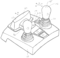
- the only figure shows a shell-like housing part 10, which is preferably made of plastic and is integrated into the interior paneling at an operator station for an industrial truck.
- Two operating levers 12 and 14 protrude from the housing part 10.
- Each of the operating levers 12, 14 has a lever head 16 which widens towards the top and forms a support surface 18 for the palm of the hand at its upper end.
- Each of the operating levers 12, 14 can be moved like a joystick along the double arrows K shown. The movement in the two arrow directions can be superimposed so that each operating lever can be swiveled in any direction. Alternatively, a lane guidance via a corresponding switching gate is also possible.
- the operating levers 12 and 14 each have a sleeve 20 which comprises a flat material folded in an accordion shape in order to shield a lever mechanism of the operating levers from environmental influences such as dust, dirt and the like.
- buttons 22, 24 are arranged between the operating levers 12, 14.
- Button 22 is equipped as a signal generator for an acoustic warning signal.
- Button 24 is intended, for example, as a confirmation button.
- buttons 22 and 24 are integrated into the housing 10 and slightly recessed.
- a switch 26 is designed as a toggle switch and protrudes from the housing 10.
- the toggle switch 26 is provided for switching between different hydraulic functions.
- the toggle switch 26 can be designed such that its toggle lever 28 is always in the neutral position shown and is switched forwards or backwards.
- the toggle switch 26 can also be designed such that the toggle lever 28 has a defined front position and a defined rear position between which switching takes place.
- the operating element also has a sliding lever 30 which can be moved along the double arrow A.
- the sliding lever 30 has a front sliding body 32 and a rear sliding body 34.
- the sliding bodies 32 and 34 are connected to one another by a web 36.
- the rear sliding body 34 is arranged in such a way that a hand resting on the operating lever 12 or 14 can press with the index finger and middle finger against the rear wall 38 of the rear sliding body 34 in order to push the slider away from the operating lever in the direction of the double arrow A.
- the rear sliding body 34 can be partially gripped behind with the index finger so that the slider as a whole is pulled towards the operating levers 12 and 14.
Landscapes
- Engineering & Computer Science (AREA)
- Transportation (AREA)
- Structural Engineering (AREA)
- Automation & Control Theory (AREA)
- Physics & Mathematics (AREA)
- General Physics & Mathematics (AREA)
- Chemical & Material Sciences (AREA)
- Combustion & Propulsion (AREA)
- Civil Engineering (AREA)
- Life Sciences & Earth Sciences (AREA)
- Geology (AREA)
- Mechanical Engineering (AREA)
- Mechanical Control Devices (AREA)
- Forklifts And Lifting Vehicles (AREA)
- Arrangement Or Mounting Of Control Devices For Change-Speed Gearing (AREA)
Description
Die vorliegende Erfindung betrifft ein Bedienelement für ein Flurförderzeug.The present invention relates to an operating element for an industrial truck.
Aus
Aus
Aus
Aus
Aus
Aus
Aus
Aus
Der Erfindung liegt die Aufgabe zugrunde, ein Bedienelement für ein Flurförderzeug zu schaffen, das eine ergonomisch günstige Bedienung für möglichst viele Funktionen auch bei unterschiedlichen Handgrößen zulässt und eine versehentliche Fehlbedienung selbst beim Tragen von Arbeitshandschuhen vermeidet.The invention is based on the object of creating an operating element for an industrial truck which allows ergonomically favorable operation for as many functions as possible even with different hand sizes and avoids accidental incorrect operation even when wearing work gloves.
Erfindungsgemäß wird die Aufgabe durch ein Bedienelement mit den Merkmalen aus Anspruch 1 gelöst. Vorteilhafte Ausgestaltungen bilden den Gegenstand der Unteransprüche.According to the invention, the object is achieved by an operating element having the features of claim 1. Advantageous embodiments form the subject matter of the subclaims.
Das erfindungsgemäße Bedienelement ist vorgesehen und bestimmt für ein Flurförderzeug. Das Bedienelement besitzt zwei Bedienhebel und mindestens einen zwischen den Bedienhebeln angeordneten Schalter. Die Bedienhebel sind jeweils für eine zweiachsige Bewegung ausgebildet, so dass jeder Bedienhebel frei in jede Richtung geneigt werden kann. Die Bedienhebel sind räumlich derart voneinander beabstandet, dass eine zwischen den Bedienhebeln positionierte Hand es zulässt, mit den Fingern beide Bedienhebel und den mindestens einen Schalter zu betätigen. Beide Bedienhebel können mit den Ballen und/oder den Fingern einer Hand ohne Umgreifen der Bedienhebel betätigt werden, so dass beide Bedienhebel ohne große Anstrengung oder unnatürliche Handhaltung gleichzeitig mit einer Hand bedient werden können. Beide Bedienhebel können ohne eine Positionsveränderung der Hand nur über die Finger bewegt werden. Auch ist der Abstand zwischen den Bedienhebeln groß genug, so dass eine Fehlbedienung der Bedienhebel oder des mindestens einen Schalters ausgeschlossen ist.The control element according to the invention is provided and intended for an industrial truck. The control element has two control levers and at least one switch arranged between the control levers. The control levers are each designed for a two-axis movement, so that each control lever can be freely tilted in any direction. The control levers are spatially spaced from one another in such a way that a hand positioned between the control levers allows both control levers and the at least one switch to be operated with the fingers. Both control levers can be operated with the balls and/or fingers of one hand without having to grasp the control levers, so that both control levers can be operated simultaneously with one hand without great effort or an unnatural hand position. Both control levers can be moved using just the fingers without changing the position of the hand. The distance between the control levers is also large enough so that incorrect operation of the control levers or the at least one switch is ruled out.
Um für die Hand eine gute Auflagefläche zu schaffen, besitzt der Bedienhebel ein sich ballig verbreiterndes Hebelende, das eine Auflagefläche für die Handfläche, insbesondere für den Handballen, bildet.In order to create a good support surface for the hand, the operating lever has a spherically widening lever end, which forms a support surface for the palm of the hand, especially for the ball of the hand.
In einer bevorzugten Ausgestaltung sind der oder die Schalter zwischen den Bedienhebeln als Taster ausgebildet. Die Taster können mit unterschiedlichen Funktionen für den Betrieb des Flurförderzeugs belegt sein. Beispielsweise kann einer der Taster als Signalgeber belegt sein. Der andere Taster kann beispielsweise als Bestätigungstaster vorgesehen sein.In a preferred embodiment, the switch or switches between the control levers are designed as buttons. The buttons can be assigned different functions for operating the industrial truck. For example, one of the buttons can be assigned as a signal generator. The other button can be provided as a confirmation button, for example.
In einer bevorzugten Ausgestaltung ist das Bedienelement mit einer schalenartigen Gehäuseabdeckung versehen, aus der die Bedienhebel vorstehen und in der der mindestens eine Taster leicht versenkt angeordnet ist. Die Gehäuseabdeckung dient als Ablage für die Hand oder den Handballen einer Bedienperson. Aus dieser Position heraus können die Bedienhebel betätigt werden. Durch den leicht versenkten Taster wird eine unabsichtliche Betätigung des Tasters vermieden.In a preferred embodiment, the operating element is provided with a shell-like housing cover from which the operating levers protrude and in which at least one button is arranged slightly recessed. The housing cover serves as a rest for the hand or the ball of the hand of an operator. The operating levers can be operated from this position. The slightly recessed button prevents the button from being accidentally operated.
In einer bevorzugten Ausgestaltung ist mindestens einem der Bedienhebel ein Umschalter zugeordnet, der mit einer oder mehreren Hydraulikfunktionen belegt ist. Der Umschalter ist bevorzugt als ein Kippschalter ausgebildet, der zwei definierte Schaltstellungen besitzt. Auch kann ein Wippschalter vorgesehen sein.In a preferred embodiment, at least one of the operating levers is assigned a changeover switch that is assigned one or more hydraulic functions. The changeover switch is preferably designed as a toggle switch that has two defined switching positions. A rocker switch can also be provided.
Erfindungsgemäß ist mittig zu den Bedienhebeln eine Schiebeschalter vorgesehen, der einen sich parallel zu einer gedachten Verbindungslinie zwischen den Bedienhebeln erstreckenden Schieber besitzt. Erfindungsgemäß wird der Schiebschalter zum Umschalten quer zu der Verbindungslinie verschoben.According to the invention, a slide switch is provided in the middle of the operating levers, which has a slider extending parallel to an imaginary connecting line between the operating levers. According to the invention, the slide switch is moved transversely to the connecting line for switching.
Ein bevorzugtes Ausführungsbeispiel für das Bedienelement wird nachfolgend näher erläutert.A preferred embodiment of the control element is explained in more detail below.
Die einzige Figur zeigt ein schalenartiges Gehäuseteil 10, das bevorzugt aus Kunststoff hergestellt ist und an einem Bedienplatz für ein Flurförderzeug in die Innenverkleidung integriert ist. Aus dem Gehäuseteil 10 stehen zwei Bedienhebel 12 und 14 vor. Jeder der Bedienhebel 12, 14 besitzt einen Hebelkopf 16, der sich nach oben verbreitert und an seinem oberen Ende eine Auflagefläche 18 für eine Handinnenfläche bildet. Jeder der Bedienhebel 12, 14 ist wie ein Joystick entlang der dargestellten Doppelpfeile K beweglich. Die Bewegung in die beiden Pfeilrichtungen kann hierbei überlagert werden, so dass jeder Bedienhebel in jede beliebige Richtung verschwenkt werden kann. Alternativ ist auch eine Gassenführung über eine entsprechende Schaltkulisse möglich.The only figure shows a shell-
Die Bedienhebel 12 und 14 besitzen jeweils eine Manschette 20, die ein zieharmonikaförmig gefaltetes Flachmaterial aufweist, um eine Hebelmechanik der Bedienhebel gegenüber Umwelteinflüssen wie Staub, Schmutz und dergleichen abzuschirmen.The operating levers 12 and 14 each have a
Zwischen den Bedienhebeln 12, 14 sind zwei Taster 22, 24 angeordnet. Der Taster 22 ist als Signalgeber für ein akustisches Warnsignal ausgestattet. Der Taster 24 ist beispielsweise als Bestätigungstaster vorgesehen. Bei dem Einsatz von Flurförderzeugen gibt es Funktionen, beispielsweise beim Verwenden von hydraulisch betätigten Klammern oder Haltearmen, bei denen vor einem Öffnen der Klammer oder der Haltearme eine separate Bestätigung durch die Bedienperson erfolgen muss, um ein unbeabsichtigtes Öffnen und Betätigen zu vermeiden. Ein solcher Bestätigungstaster ist beispielsweise der Taster 24. Die Taster 22 und 24 sind in das Gehäuse 10 integriert und leicht versenkt.Two
Ein Schalter 26 ist als Kippschalter ausgebildet und steht aus dem Gehäuse 10 vor. Der Kippschalter 26 ist zum Umschalten zwischen unterschiedlichen Hydraulikfunktionen vorgesehen. Hierbei kann der Kippschalter 26 derart ausgebildet sein, dass sein Kipphebel 28 stets in der dargestellten neutralen Position steht und nach vorne oder nach hinten umgeschaltet wird. Alternativ kann der Kippschalter 26 auch so ausgebildet sein, dass der Kipphebel 28 eine vordere definierte Position und eine hintere definierte Position besitzt, zwischen denen umgeschaltet wird.A switch 26 is designed as a toggle switch and protrudes from the
Das Bedienelement besitzt ferner einen Schiebehebel 30, der entlang des Doppelpfeils A verschiebbar ist. Der Schiebehebel 30 besitzt einen vorderen Schiebekörper 32 und einen hinteren Schiebekörper 34. Die Schiebekörper 32 und 34 sind durch einen Steg 36 miteinander verbunden. Der hintere Schiebekörper 34 ist dabei so angeordnet, dass eine auf dem Bedienhebel 12 oder 14 ruhende Hand mit dem Zeigefinger und dem Mittelfinger gegen die rückwärtige Wand 38 des hinteren Schiebekörpers 34 drücken kann, um den Schieber in Richtung des Doppelpfeils A von dem Bedienhebel fortzuschieben. Beim Heranziehen des Schiebers kann der hintere Schiebekörper 34 teilweise mit dem Zeigefinger hintergriffen werden, so dass der Schieber insgesamt auf die Bedienhebel 12 und 14 zugezogen wird.The operating element also has a
Claims (7)
- A control element for an industrial truck, with two control levers (12, 14) and at least one switch (22, 24) arranged between the control levers, wherein the control levers (12, 14) are each one configured for a biaxial movement (K), characterised in that the control levers are spatially spaced apart from each other such that by a hand which is positioned between the levers, the control levers and the at least one switch (22, 24)between the control levers can be actuated by the fingers without the need to reach round, wherein both control levers can be moved only via the fingers without any position change of the hand and a slide switch (30) is provided in the middle between the control levers, which has at least one sliding body (32, 34), extending parallel to an imaginary connection line between the control levers (12, 14), wherein the slide switch (30) is moved transversely to its connection line in order to switch over.
- The control element according to claim 1, characterised in that each of the control levers (12, 14) has a convexly enlarging lever end (16).
- A control element according to claim 1 or 2, characterised in that the one or the several switch(es) (22, 24) is/are realised as push button(s).
- A control element according to any one of claims 1 to 3, characterised in that two push buttons (22, 24) are provided between the control levers (12, 14).
- A control element according to any one of claims 1 to 4, characterised in that a housing cover (10) is provided, from out which the control levers (12, 14) project and in which the at least one switch (22, 24) is arranged so as to be sunk in a recess.
- The control element according to claim 5, characterised ion that the hand positioned between the levers rests on the housing cover with its thumb ball.
- A control element according to any one of claims 1 to 6, characterised in that a changeover switch (26) for one or several hydraulic functions on the industrial truck is associated to at least one control lever (12).
Applications Claiming Priority (1)
| Application Number | Priority Date | Filing Date | Title |
|---|---|---|---|
| DE102013012176.0A DE102013012176A1 (en) | 2013-07-22 | 2013-07-22 | Operating element for an industrial truck |
Publications (3)
| Publication Number | Publication Date |
|---|---|
| EP2829503A1 EP2829503A1 (en) | 2015-01-28 |
| EP2829503B1 EP2829503B1 (en) | 2016-01-20 |
| EP2829503B2 true EP2829503B2 (en) | 2024-08-28 |
Family
ID=51212693
Family Applications (1)
| Application Number | Title | Priority Date | Filing Date |
|---|---|---|---|
| EP14177269.9A Active EP2829503B2 (en) | 2013-07-22 | 2014-07-16 | Operating element for an industrial truck |
Country Status (5)
| Country | Link |
|---|---|
| US (1) | US20150033899A1 (en) |
| EP (1) | EP2829503B2 (en) |
| CN (1) | CN104391539B (en) |
| DE (1) | DE102013012176A1 (en) |
| ES (1) | ES2567423T5 (en) |
Families Citing this family (8)
| Publication number | Priority date | Publication date | Assignee | Title |
|---|---|---|---|---|
| JP6247174B2 (en) * | 2014-08-01 | 2017-12-13 | 株式会社クボタ | Driving support system |
| USD789264S1 (en) * | 2016-01-21 | 2017-06-13 | Pilot, Inc. | Shift knob cover |
| USD789263S1 (en) * | 2016-01-21 | 2017-06-13 | Pilot, Inc. | Shift knob cover |
| AU2017213884B2 (en) | 2016-02-05 | 2022-09-15 | Crown Equipment Corporation | Control elements for materials handling vehicles |
| DE102016118459A1 (en) | 2016-09-29 | 2018-03-29 | Jungheinrich Aktiengesellschaft | Industrial truck with an operating lever having an operating means and method for operating such a truck |
| DE102016118458A1 (en) | 2016-09-29 | 2018-03-29 | Jungheinrich Aktiengesellschaft | Method for operating an industrial truck with a control element |
| DE102016118457A1 (en) | 2016-09-29 | 2018-03-29 | Jungheinrich Aktiengesellschaft | Method for operating an industrial truck with a control element and an industrial truck |
| JP7185789B2 (en) * | 2019-04-04 | 2022-12-07 | ジェイエルジー インダストリーズ インク. | Control station for small vehicles |
Citations (3)
| Publication number | Priority date | Publication date | Assignee | Title |
|---|---|---|---|---|
| GB2325211A (en) † | 1997-05-16 | 1998-11-18 | Lansing Linde Ltd | An operating arrangement for a load supporting device on a lift truck |
| EP1350669A2 (en) † | 2002-04-03 | 2003-10-08 | Kabushiki Kaisha Toyota Jidoshokki | Operating member and armrest for industrial vehicle |
| US8104566B2 (en) † | 2008-03-07 | 2012-01-31 | Deere & Company | Arrangement of steering wheel and operator seat assembly |
Family Cites Families (28)
| Publication number | Priority date | Publication date | Assignee | Title |
|---|---|---|---|---|
| IT1145601B (en) * | 1981-12-21 | 1986-11-05 | Lear Snc Di Foggini E C | CONTROL LEVER PARTICULARLY FOR VEHICLE SPEED WAGONS AND ITS MANUFACTURING PROCEDURE |
| IT8553363U1 (en) * | 1985-05-10 | 1986-11-10 | Foggini Progetti | PREFORMED FULL COVERING FOR GEAR CHANGE CONTROL LEVERS OF MOTOR VEHICLES |
| SE507063C2 (en) | 1993-11-29 | 1998-03-23 | Bt Ind Ab | Support arm with lift truck control |
| DE29714284U1 (en) | 1997-08-09 | 1997-10-16 | Jungheinrich Ag, 22047 Hamburg | Manually operated control device for the operating position or seat of a reach truck |
| SE520647C2 (en) | 1999-04-23 | 2003-08-05 | Atlet Ab | Hand control device for work vehicles |
| US6634453B2 (en) * | 2001-08-29 | 2003-10-21 | Deere & Company | Ergonomic tractor seat armrest and hand control |
| WO2003030092A1 (en) * | 2001-09-04 | 2003-04-10 | Ziad Badarneh | Operating device for controlling functions in electronic equipment |
| JP4291544B2 (en) * | 2002-04-03 | 2009-07-08 | 株式会社豊田自動織機 | Industrial vehicle |
| DE10344029A1 (en) * | 2003-09-23 | 2005-04-14 | Still Gmbh | Multifunction lever and operating unit for a truck |
| US7218313B2 (en) * | 2003-10-31 | 2007-05-15 | Zeetoo, Inc. | Human interface system |
| US7178623B2 (en) * | 2003-12-19 | 2007-02-20 | Caterpillar Inc | Operator control assembly |
| US7063321B2 (en) * | 2004-06-10 | 2006-06-20 | Intec, Inc. | Gel grip controller |
| US7290635B2 (en) * | 2004-07-02 | 2007-11-06 | Caterpillar Inc. | Work machine operator control station with moveably attached controller |
| US7635045B2 (en) * | 2004-07-30 | 2009-12-22 | Caterpillar Inc. | Machine tool control console |
| DE102005007789A1 (en) | 2005-02-19 | 2006-08-24 | Jungheinrich Aktiengesellschaft | Manually operated operating device for an industrial workstation of a truck |
| JP4852912B2 (en) * | 2005-07-15 | 2012-01-11 | 株式会社豊田自動織機 | Industrial vehicle |
| JP4596020B2 (en) * | 2008-03-07 | 2010-12-08 | 株式会社デンソー | Vehicle control device |
| US8333250B2 (en) * | 2008-03-07 | 2012-12-18 | Deere & Company | Mounting console with visibility improvements |
| US7806470B2 (en) * | 2008-11-20 | 2010-10-05 | Deere & Company | Vehicle command armrest assembly |
| WO2010085184A1 (en) * | 2009-01-20 | 2010-07-29 | Husqvarna Ab | Control system for a remote control work machine |
| DE102009032493A1 (en) * | 2009-07-09 | 2011-01-13 | Linde Material Handling Gmbh | Operating device and operating device system for industrial trucks |
| JPWO2011092746A1 (en) * | 2010-01-29 | 2013-05-23 | 三菱電機株式会社 | Map information processing device |
| US9567065B2 (en) * | 2010-10-07 | 2017-02-14 | Bae Systems Plc | Vehicle armrest |
| GB201020499D0 (en) * | 2010-12-03 | 2011-01-19 | Valtra Oy Ab | Driver interface module |
| CN103038028B (en) * | 2011-01-27 | 2015-05-27 | 松下电器产业株式会社 | Robot-arm control device and control method, robot, and integrated electronic circuit |
| AU2012258458B9 (en) * | 2011-12-01 | 2014-11-06 | Joy Global Surface Mining Inc | Cab module for a mining machine |
| JP6317202B2 (en) * | 2014-07-08 | 2018-04-25 | 株式会社クボタ | Multifunctional operation tool and armrest operation device |
| US10036139B2 (en) * | 2014-11-24 | 2018-07-31 | Caterpillar Inc. | Machine input device having multi-axis tool control |
-
2013
- 2013-07-22 DE DE102013012176.0A patent/DE102013012176A1/en not_active Ceased
-
2014
- 2014-07-16 ES ES14177269T patent/ES2567423T5/en active Active
- 2014-07-16 EP EP14177269.9A patent/EP2829503B2/en active Active
- 2014-07-21 US US14/336,673 patent/US20150033899A1/en not_active Abandoned
- 2014-07-22 CN CN201410539360.9A patent/CN104391539B/en active Active
Patent Citations (3)
| Publication number | Priority date | Publication date | Assignee | Title |
|---|---|---|---|---|
| GB2325211A (en) † | 1997-05-16 | 1998-11-18 | Lansing Linde Ltd | An operating arrangement for a load supporting device on a lift truck |
| EP1350669A2 (en) † | 2002-04-03 | 2003-10-08 | Kabushiki Kaisha Toyota Jidoshokki | Operating member and armrest for industrial vehicle |
| US8104566B2 (en) † | 2008-03-07 | 2012-01-31 | Deere & Company | Arrangement of steering wheel and operator seat assembly |
Also Published As
| Publication number | Publication date |
|---|---|
| CN104391539A (en) | 2015-03-04 |
| ES2567423T3 (en) | 2016-04-22 |
| CN104391539B (en) | 2018-05-18 |
| DE102013012176A1 (en) | 2015-01-22 |
| EP2829503A1 (en) | 2015-01-28 |
| EP2829503B1 (en) | 2016-01-20 |
| ES2567423T5 (en) | 2025-03-04 |
| US20150033899A1 (en) | 2015-02-05 |
Similar Documents
| Publication | Publication Date | Title |
|---|---|---|
| EP2829503B2 (en) | Operating element for an industrial truck | |
| EP1288763B1 (en) | Apparatus for controlling an agricultural vehicle | |
| DE19624463A1 (en) | Control device for commercial vehicles, in particular for agricultural tractors | |
| EP1632426B1 (en) | Drawbar for a forklift truck | |
| DE3925872C2 (en) | ||
| EP1693334B1 (en) | Hand operated control device for the operator's compartment of a industrial vehicle | |
| DE19951379C2 (en) | Manually operated steering element for an industrial truck | |
| EP1727728A1 (en) | Control element | |
| DE102020001889A1 (en) | Control element arrangement for a mobile work device and a method for carrying out a steering process in such a work device | |
| EP2880503A1 (en) | Manual control element, particularly for a construction machine | |
| DE19956870B4 (en) | Hand-operated steering mechanism for vehicles | |
| DE60011786T2 (en) | Actuating device for working vehicles | |
| EP1747964B1 (en) | Operating element with mini lever | |
| EP1775254B1 (en) | Control panel with a thumb controlled joystick for an industrial truck | |
| EP3054367B1 (en) | Vehicle, in particular tracked vehicle for piste design and maintenance | |
| EP3009325B1 (en) | Steering wheel of a industrial truck comprising a driver workplace | |
| DE102014208349B4 (en) | Motor vehicle with a device for at least partially controlling the longitudinal and/or transverse dynamics of the motor vehicle by hand | |
| EP1748026B1 (en) | Operating arrangement for an industrial truck | |
| DE10235159B4 (en) | Adjustable steering wheel for motor vehicles | |
| EP2075216B1 (en) | Tiller head for an industrial truck | |
| DE102023001993B3 (en) | Steer-by-wire steering wheel for a motor vehicle and method | |
| DE102008045731B4 (en) | Tiller head for an industrial truck | |
| DE102014112896B4 (en) | Industrial truck with a display and control device | |
| DE102019125984B3 (en) | Holding device for a mobile device in a motor vehicle | |
| DE10205876A1 (en) | Operating lever for fork lift truck, incorporates forward and reverse travel switch |
Legal Events
| Date | Code | Title | Description |
|---|---|---|---|
| 17P | Request for examination filed |
Effective date: 20140716 |
|
| AK | Designated contracting states |
Kind code of ref document: A1 Designated state(s): AL AT BE BG CH CY CZ DE DK EE ES FI FR GB GR HR HU IE IS IT LI LT LU LV MC MK MT NL NO PL PT RO RS SE SI SK SM TR |
|
| AX | Request for extension of the european patent |
Extension state: BA ME |
|
| PUAI | Public reference made under article 153(3) epc to a published international application that has entered the european phase |
Free format text: ORIGINAL CODE: 0009012 |
|
| R17P | Request for examination filed (corrected) |
Effective date: 20150715 |
|
| RBV | Designated contracting states (corrected) |
Designated state(s): AL AT BE BG CH CY CZ DE DK EE ES FI FR GB GR HR HU IE IS IT LI LT LU LV MC MK MT NL NO PL PT RO RS SE SI SK SM TR |
|
| GRAP | Despatch of communication of intention to grant a patent |
Free format text: ORIGINAL CODE: EPIDOSNIGR1 |
|
| RIC1 | Information provided on ipc code assigned before grant |
Ipc: G05G 11/00 20060101ALI20150814BHEP Ipc: B66F 9/20 20060101AFI20150814BHEP Ipc: G05G 1/04 20060101ALI20150814BHEP |
|
| INTG | Intention to grant announced |
Effective date: 20150903 |
|
| GRAS | Grant fee paid |
Free format text: ORIGINAL CODE: EPIDOSNIGR3 |
|
| GRAA | (expected) grant |
Free format text: ORIGINAL CODE: 0009210 |
|
| AK | Designated contracting states |
Kind code of ref document: B1 Designated state(s): AL AT BE BG CH CY CZ DE DK EE ES FI FR GB GR HR HU IE IS IT LI LT LU LV MC MK MT NL NO PL PT RO RS SE SI SK SM TR |
|
| REG | Reference to a national code |
Ref country code: GB Ref legal event code: FG4D Free format text: NOT ENGLISH |
|
| REG | Reference to a national code |
Ref country code: CH Ref legal event code: EP |
|
| REG | Reference to a national code |
Ref country code: IE Ref legal event code: FG4D Free format text: LANGUAGE OF EP DOCUMENT: GERMAN |
|
| REG | Reference to a national code |
Ref country code: AT Ref legal event code: REF Ref document number: 771638 Country of ref document: AT Kind code of ref document: T Effective date: 20160215 |
|
| REG | Reference to a national code |
Ref country code: DE Ref legal event code: R096 Ref document number: 502014000317 Country of ref document: DE |
|
| REG | Reference to a national code |
Ref country code: ES Ref legal event code: FG2A Ref document number: 2567423 Country of ref document: ES Kind code of ref document: T3 Effective date: 20160422 |
|
| REG | Reference to a national code |
Ref country code: LT Ref legal event code: MG4D Ref country code: NL Ref legal event code: MP Effective date: 20160120 |
|
| PG25 | Lapsed in a contracting state [announced via postgrant information from national office to epo] |
Ref country code: NL Free format text: LAPSE BECAUSE OF FAILURE TO SUBMIT A TRANSLATION OF THE DESCRIPTION OR TO PAY THE FEE WITHIN THE PRESCRIBED TIME-LIMIT Effective date: 20160120 |
|
| REG | Reference to a national code |
Ref country code: FR Ref legal event code: PLFP Year of fee payment: 3 |
|
| PG25 | Lapsed in a contracting state [announced via postgrant information from national office to epo] |
Ref country code: HR Free format text: LAPSE BECAUSE OF FAILURE TO SUBMIT A TRANSLATION OF THE DESCRIPTION OR TO PAY THE FEE WITHIN THE PRESCRIBED TIME-LIMIT Effective date: 20160120 Ref country code: FI Free format text: LAPSE BECAUSE OF FAILURE TO SUBMIT A TRANSLATION OF THE DESCRIPTION OR TO PAY THE FEE WITHIN THE PRESCRIBED TIME-LIMIT Effective date: 20160120 Ref country code: GR Free format text: LAPSE BECAUSE OF FAILURE TO SUBMIT A TRANSLATION OF THE DESCRIPTION OR TO PAY THE FEE WITHIN THE PRESCRIBED TIME-LIMIT Effective date: 20160421 Ref country code: NO Free format text: LAPSE BECAUSE OF FAILURE TO SUBMIT A TRANSLATION OF THE DESCRIPTION OR TO PAY THE FEE WITHIN THE PRESCRIBED TIME-LIMIT Effective date: 20160420 |
|
| PG25 | Lapsed in a contracting state [announced via postgrant information from national office to epo] |
Ref country code: PT Free format text: LAPSE BECAUSE OF FAILURE TO SUBMIT A TRANSLATION OF THE DESCRIPTION OR TO PAY THE FEE WITHIN THE PRESCRIBED TIME-LIMIT Effective date: 20160520 Ref country code: IS Free format text: LAPSE BECAUSE OF FAILURE TO SUBMIT A TRANSLATION OF THE DESCRIPTION OR TO PAY THE FEE WITHIN THE PRESCRIBED TIME-LIMIT Effective date: 20160520 Ref country code: PL Free format text: LAPSE BECAUSE OF FAILURE TO SUBMIT A TRANSLATION OF THE DESCRIPTION OR TO PAY THE FEE WITHIN THE PRESCRIBED TIME-LIMIT Effective date: 20160120 Ref country code: LT Free format text: LAPSE BECAUSE OF FAILURE TO SUBMIT A TRANSLATION OF THE DESCRIPTION OR TO PAY THE FEE WITHIN THE PRESCRIBED TIME-LIMIT Effective date: 20160120 Ref country code: LV Free format text: LAPSE BECAUSE OF FAILURE TO SUBMIT A TRANSLATION OF THE DESCRIPTION OR TO PAY THE FEE WITHIN THE PRESCRIBED TIME-LIMIT Effective date: 20160120 Ref country code: SE Free format text: LAPSE BECAUSE OF FAILURE TO SUBMIT A TRANSLATION OF THE DESCRIPTION OR TO PAY THE FEE WITHIN THE PRESCRIBED TIME-LIMIT Effective date: 20160120 Ref country code: RS Free format text: LAPSE BECAUSE OF FAILURE TO SUBMIT A TRANSLATION OF THE DESCRIPTION OR TO PAY THE FEE WITHIN THE PRESCRIBED TIME-LIMIT Effective date: 20160120 |
|
| REG | Reference to a national code |
Ref country code: DE Ref legal event code: R026 Ref document number: 502014000317 Country of ref document: DE |
|
| PLBI | Opposition filed |
Free format text: ORIGINAL CODE: 0009260 |
|
| PG25 | Lapsed in a contracting state [announced via postgrant information from national office to epo] |
Ref country code: DK Free format text: LAPSE BECAUSE OF FAILURE TO SUBMIT A TRANSLATION OF THE DESCRIPTION OR TO PAY THE FEE WITHIN THE PRESCRIBED TIME-LIMIT Effective date: 20160120 Ref country code: EE Free format text: LAPSE BECAUSE OF FAILURE TO SUBMIT A TRANSLATION OF THE DESCRIPTION OR TO PAY THE FEE WITHIN THE PRESCRIBED TIME-LIMIT Effective date: 20160120 |
|
| 26 | Opposition filed |
Opponent name: LINDE MATERIAL HANDLING GMBH Effective date: 20161012 |
|
| PLAX | Notice of opposition and request to file observation + time limit sent |
Free format text: ORIGINAL CODE: EPIDOSNOBS2 |
|
| PG25 | Lapsed in a contracting state [announced via postgrant information from national office to epo] |
Ref country code: SM Free format text: LAPSE BECAUSE OF FAILURE TO SUBMIT A TRANSLATION OF THE DESCRIPTION OR TO PAY THE FEE WITHIN THE PRESCRIBED TIME-LIMIT Effective date: 20160120 Ref country code: CZ Free format text: LAPSE BECAUSE OF FAILURE TO SUBMIT A TRANSLATION OF THE DESCRIPTION OR TO PAY THE FEE WITHIN THE PRESCRIBED TIME-LIMIT Effective date: 20160120 Ref country code: RO Free format text: LAPSE BECAUSE OF FAILURE TO SUBMIT A TRANSLATION OF THE DESCRIPTION OR TO PAY THE FEE WITHIN THE PRESCRIBED TIME-LIMIT Effective date: 20160120 Ref country code: SK Free format text: LAPSE BECAUSE OF FAILURE TO SUBMIT A TRANSLATION OF THE DESCRIPTION OR TO PAY THE FEE WITHIN THE PRESCRIBED TIME-LIMIT Effective date: 20160120 |
|
| PG25 | Lapsed in a contracting state [announced via postgrant information from national office to epo] |
Ref country code: BE Free format text: LAPSE BECAUSE OF NON-PAYMENT OF DUE FEES Effective date: 20160731 |
|
| PLAB | Opposition data, opponent's data or that of the opponent's representative modified |
Free format text: ORIGINAL CODE: 0009299OPPO |
|
| PG25 | Lapsed in a contracting state [announced via postgrant information from national office to epo] |
Ref country code: BG Free format text: LAPSE BECAUSE OF FAILURE TO SUBMIT A TRANSLATION OF THE DESCRIPTION OR TO PAY THE FEE WITHIN THE PRESCRIBED TIME-LIMIT Effective date: 20160420 Ref country code: SI Free format text: LAPSE BECAUSE OF FAILURE TO SUBMIT A TRANSLATION OF THE DESCRIPTION OR TO PAY THE FEE WITHIN THE PRESCRIBED TIME-LIMIT Effective date: 20160120 |
|
| R26 | Opposition filed (corrected) |
Opponent name: LINDE MATERIAL HANDLING GMBH Effective date: 20161012 |
|
| PLAB | Opposition data, opponent's data or that of the opponent's representative modified |
Free format text: ORIGINAL CODE: 0009299OPPO |
|
| PG25 | Lapsed in a contracting state [announced via postgrant information from national office to epo] |
Ref country code: MC Free format text: LAPSE BECAUSE OF FAILURE TO SUBMIT A TRANSLATION OF THE DESCRIPTION OR TO PAY THE FEE WITHIN THE PRESCRIBED TIME-LIMIT Effective date: 20160120 |
|
| PLBB | Reply of patent proprietor to notice(s) of opposition received |
Free format text: ORIGINAL CODE: EPIDOSNOBS3 |
|
| R26 | Opposition filed (corrected) |
Opponent name: LINDE MATERIAL HANDLING GMBH Effective date: 20161012 |
|
| REG | Reference to a national code |
Ref country code: IE Ref legal event code: MM4A |
|
| REG | Reference to a national code |
Ref country code: FR Ref legal event code: PLFP Year of fee payment: 4 |
|
| PG25 | Lapsed in a contracting state [announced via postgrant information from national office to epo] |
Ref country code: IE Free format text: LAPSE BECAUSE OF NON-PAYMENT OF DUE FEES Effective date: 20160716 |
|
| PG25 | Lapsed in a contracting state [announced via postgrant information from national office to epo] |
Ref country code: LU Free format text: LAPSE BECAUSE OF NON-PAYMENT OF DUE FEES Effective date: 20160716 |
|
| REG | Reference to a national code |
Ref country code: CH Ref legal event code: PL |
|
| PG25 | Lapsed in a contracting state [announced via postgrant information from national office to epo] |
Ref country code: CH Free format text: LAPSE BECAUSE OF NON-PAYMENT OF DUE FEES Effective date: 20170731 Ref country code: LI Free format text: LAPSE BECAUSE OF NON-PAYMENT OF DUE FEES Effective date: 20170731 |
|
| PG25 | Lapsed in a contracting state [announced via postgrant information from national office to epo] |
Ref country code: HU Free format text: LAPSE BECAUSE OF FAILURE TO SUBMIT A TRANSLATION OF THE DESCRIPTION OR TO PAY THE FEE WITHIN THE PRESCRIBED TIME-LIMIT; INVALID AB INITIO Effective date: 20140716 |
|
| PG25 | Lapsed in a contracting state [announced via postgrant information from national office to epo] |
Ref country code: MT Free format text: LAPSE BECAUSE OF FAILURE TO SUBMIT A TRANSLATION OF THE DESCRIPTION OR TO PAY THE FEE WITHIN THE PRESCRIBED TIME-LIMIT Effective date: 20160120 Ref country code: CY Free format text: LAPSE BECAUSE OF FAILURE TO SUBMIT A TRANSLATION OF THE DESCRIPTION OR TO PAY THE FEE WITHIN THE PRESCRIBED TIME-LIMIT Effective date: 20160120 Ref country code: MK Free format text: LAPSE BECAUSE OF FAILURE TO SUBMIT A TRANSLATION OF THE DESCRIPTION OR TO PAY THE FEE WITHIN THE PRESCRIBED TIME-LIMIT Effective date: 20160120 |
|
| REG | Reference to a national code |
Ref country code: FR Ref legal event code: PLFP Year of fee payment: 5 |
|
| PLCK | Communication despatched that opposition was rejected |
Free format text: ORIGINAL CODE: EPIDOSNREJ1 |
|
| STAA | Information on the status of an ep patent application or granted ep patent |
Free format text: STATUS: THE PATENT HAS BEEN GRANTED |
|
| PG25 | Lapsed in a contracting state [announced via postgrant information from national office to epo] |
Ref country code: TR Free format text: LAPSE BECAUSE OF FAILURE TO SUBMIT A TRANSLATION OF THE DESCRIPTION OR TO PAY THE FEE WITHIN THE PRESCRIBED TIME-LIMIT Effective date: 20160120 Ref country code: AL Free format text: LAPSE BECAUSE OF FAILURE TO SUBMIT A TRANSLATION OF THE DESCRIPTION OR TO PAY THE FEE WITHIN THE PRESCRIBED TIME-LIMIT Effective date: 20160120 |
|
| APBM | Appeal reference recorded |
Free format text: ORIGINAL CODE: EPIDOSNREFNO |
|
| APBP | Date of receipt of notice of appeal recorded |
Free format text: ORIGINAL CODE: EPIDOSNNOA2O |
|
| APAH | Appeal reference modified |
Free format text: ORIGINAL CODE: EPIDOSCREFNO |
|
| APBQ | Date of receipt of statement of grounds of appeal recorded |
Free format text: ORIGINAL CODE: EPIDOSNNOA3O |
|
| REG | Reference to a national code |
Ref country code: AT Ref legal event code: MM01 Ref document number: 771638 Country of ref document: AT Kind code of ref document: T Effective date: 20190716 |
|
| PG25 | Lapsed in a contracting state [announced via postgrant information from national office to epo] |
Ref country code: AT Free format text: LAPSE BECAUSE OF NON-PAYMENT OF DUE FEES Effective date: 20190716 |
|
| APBU | Appeal procedure closed |
Free format text: ORIGINAL CODE: EPIDOSNNOA9O |
|
| PLAY | Examination report in opposition despatched + time limit |
Free format text: ORIGINAL CODE: EPIDOSNORE2 |
|
| PLBC | Reply to examination report in opposition received |
Free format text: ORIGINAL CODE: EPIDOSNORE3 |
|
| PUAH | Patent maintained in amended form |
Free format text: ORIGINAL CODE: 0009272 |
|
| STAA | Information on the status of an ep patent application or granted ep patent |
Free format text: STATUS: PATENT MAINTAINED AS AMENDED |
|
| 27A | Patent maintained in amended form |
Effective date: 20240828 |
|
| AK | Designated contracting states |
Kind code of ref document: B2 Designated state(s): AL AT BE BG CH CY CZ DE DK EE ES FI FR GB GR HR HU IE IS IT LI LT LU LV MC MK MT NL NO PL PT RO RS SE SI SK SM TR |
|
| REG | Reference to a national code |
Ref country code: DE Ref legal event code: R102 Ref document number: 502014000317 Country of ref document: DE |
|
| REG | Reference to a national code |
Ref country code: ES Ref legal event code: DC2A Ref document number: 2567423 Country of ref document: ES Kind code of ref document: T5 Effective date: 20250304 |
|
| PGFP | Annual fee paid to national office [announced via postgrant information from national office to epo] |
Ref country code: ES Payment date: 20250819 Year of fee payment: 12 |
|
| PGFP | Annual fee paid to national office [announced via postgrant information from national office to epo] |
Ref country code: DE Payment date: 20250722 Year of fee payment: 12 |
|
| PGFP | Annual fee paid to national office [announced via postgrant information from national office to epo] |
Ref country code: IT Payment date: 20250731 Year of fee payment: 12 |
|
| PGFP | Annual fee paid to national office [announced via postgrant information from national office to epo] |
Ref country code: GB Payment date: 20250724 Year of fee payment: 12 |
|
| PGFP | Annual fee paid to national office [announced via postgrant information from national office to epo] |
Ref country code: FR Payment date: 20250723 Year of fee payment: 12 |