EP2829308B1 - Dispositif de distribution de liquide - Google Patents
Dispositif de distribution de liquide Download PDFInfo
- Publication number
- EP2829308B1 EP2829308B1 EP12871946.5A EP12871946A EP2829308B1 EP 2829308 B1 EP2829308 B1 EP 2829308B1 EP 12871946 A EP12871946 A EP 12871946A EP 2829308 B1 EP2829308 B1 EP 2829308B1
- Authority
- EP
- European Patent Office
- Prior art keywords
- unit
- liquid
- dispensing
- disposed
- housing
- Prior art date
- Legal status (The legal status is an assumption and is not a legal conclusion. Google has not performed a legal analysis and makes no representation as to the accuracy of the status listed.)
- Not-in-force
Links
Images

Classifications
-
- B—PERFORMING OPERATIONS; TRANSPORTING
- B01—PHYSICAL OR CHEMICAL PROCESSES OR APPARATUS IN GENERAL
- B01D—SEPARATION
- B01D3/00—Distillation or related exchange processes in which liquids are contacted with gaseous media, e.g. stripping
- B01D3/14—Fractional distillation or use of a fractionation or rectification column
- B01D3/32—Other features of fractionating columns ; Constructional details of fractionating columns not provided for in groups B01D3/16 - B01D3/30
-
- B—PERFORMING OPERATIONS; TRANSPORTING
- B01—PHYSICAL OR CHEMICAL PROCESSES OR APPARATUS IN GENERAL
- B01D—SEPARATION
- B01D3/00—Distillation or related exchange processes in which liquids are contacted with gaseous media, e.g. stripping
- B01D3/008—Liquid distribution
-
- B—PERFORMING OPERATIONS; TRANSPORTING
- B01—PHYSICAL OR CHEMICAL PROCESSES OR APPARATUS IN GENERAL
- B01D—SEPARATION
- B01D3/00—Distillation or related exchange processes in which liquids are contacted with gaseous media, e.g. stripping
-
- B—PERFORMING OPERATIONS; TRANSPORTING
- B01—PHYSICAL OR CHEMICAL PROCESSES OR APPARATUS IN GENERAL
- B01D—SEPARATION
- B01D3/00—Distillation or related exchange processes in which liquids are contacted with gaseous media, e.g. stripping
- B01D3/14—Fractional distillation or use of a fractionation or rectification column
- B01D3/141—Fractional distillation or use of a fractionation or rectification column where at least one distillation column contains at least one dividing wall
Definitions
- the present invention relates to a liquid dispensing device, and in particular to a liquid dispensing device which is installed inside of a distillation column, thus continuously supplying liquid after the supply ratio of liquid is precisely adjusted.
- a liquid dispensing device is generally installed at a washing tower, a absorption tower, etc. in the fields of oil refining, petro-chemistry and fine chemistry, which operates based on distillation, absorption and cooling principle so as to eliminate noxious gas or organic matter.
- a divide wall column As a device used for distillation, absorption and cooling in industry fields, there is a column designed to separate a predetermined substance through air-liquid contacts.
- a divide wall column is generally used in recent years, which is configured to a structure constituted by combining two columns into one column. In this case, it needs to dispense, by using a pair of lower separation walls, the liquid present in the upper side into a predetermined ratio. At this moment, the liquid dispensing device adjusts a supply ratio of liquid.
- a distillation apparatus including a column body; partitions for dividing the interior of the column body into first chambers and second chambers, which are adjacent to each other; a feed nozzle for feeding into the column body a material liquid; a first distillation section including an enriching section located at an upper portion thereof and an exhaust section located at a lower portion thereof; a second distillation section including an enriching section located at an upper portion thereof and an exhaust section located at a lower portion thereof; a third distillation section including an enriching section located at an upper portion thereof and an exhaust section located at a lower portion thereof; first discharge means for discharging a first component; second discharge means for discharging a second component; and third discharge means for discharging a third component.
- the partitions are biased such that the cross-sectional area of the first chambers differs from that of the second chambers.
- a pressure loss arising in the first chambers and sum of pressure losses arising in the second chambers can be equalized, thereby eliminating influence of descending liquid on ascending vapor.
- the present invention is made in an effort to improve the above-mentioned problems. It is an object of the present invention to provide a liquid dispensing device whose construction for dispensing liquid is disposed inside of the distillation thus makes it possible to save the whole installation space.
- a liquid dispensing device comprising a housing disposed inside of a distillation column; lattice -shaped upper and lower grids which are disposed at the inner sides of top and bottom of the housing; a collector tray disposed at top of the inner side of the housing for thereby guiding the liquid inputted through the upper grid; a porous plate which is disposed at top of the collector tray and includes a plurality of through holes through which the guided liquid descends; a dispensing box which is disposed at a lower side of the porous plate and is configured to dispense the liquid which descends through the porous plate, through an outlet tube connected to both sides thereof to the outside of the housing; a liquid dispenser which is disposed at a lower side of the dispensing box and is configured to uniformly dispense and discharge the liquid dispensed by the dispensing box toward the lower side; a connection pipe connected to enable a fluid flow between the dispensing box and the liquid dispenser; an inlet pipe configured to enable a liquid input
- the collector tray comprises a body plate; a plurality of risers which pass through the body plate for thereby enabling gas movement between the upper side and the lower side of the body plate; and a hat which is obliquely disposed on tops of the risers toward the porous plate for thereby preventing the liquid inputted through the upper grid from entering the risers.
- a sump which has a ⁇ -shaped cross section and is configured to interconnect the body plate and the porous plate.
- the dispensing box comprises a box body which is formed in a rectangular parallelepiped shape and whose top is open; a first unit partition which is disposed inside of the box body and is configured to divide the inner side of the box body into a first unit chamber and a second unit chamber; and a second unit partition which is configured to interconnect the first unit partition and the inner wall of the box body for thereby forming a unit separation space.
- the height of the first unit partition is lower than the height of the box body, and the height of the second unit partition is lower than the height of the first unit partition.
- the first and second unit partitions are symmetrically disposed at both ends of the inner side of the box body.
- the outlet tube is connected to discharge the liquid in the unit separation space to the outside, and the outlet tube is connected to the inlet tube in such a way to enable the discharged liquid to enter the liquid dispenser.
- the liquid dispenser comprises a first unit dispensing unit which is formed in a hexahedron shape and whose top and bottom are open, and which is symmetrically disposed with respect to the first and second chambers; and a plurality of second unit dispensing units which are symmetrically disposed at both sides of the first unit dispensing unit and are connected to the first unit dispensing unit in such a way to enable the liquid to flow between the second unit dispensing units and the first unit dispensing unit.
- connection tube is configured to connect the first unit dispensing unit to the lower sides of the first and second unit chambers.
- the liquid dispensing device according to the present invention has advantageous effects in the way that the whole installation space may be saved because the construction for a liquid dispensing device configured to dispense liquid may be arranged inside of the distillation column.
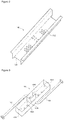
- Figure 1 is a perspective view illustrating a construction of a liquid dispensing device according to an exemplary embodiment of the present invention.
- the liquid dispensing device 100 comprises a housing 110, upper and lower grids 120a and 120b, a collector tray 130, a porous plate 150, a dispensing box 160, a liquid dispensing unit 170 and a separation wall 190.
- the distillation column according to the present invention is a device configured to separate a predetermined substance through air-liquid contacts and is well known, so the detailed descriptions thereof will be omitted.
- the housing 110 is disposed inside of the distillation column and is configured to isolate other components inside of the distillation column and the components which will be described later.
- the housing 110 is configured in a cylindrical shape; however it may be configured in a variety of shapes based on a user's demand.
- the upper and lower grids 120a and 120b are arranged at top and bottom of the inner side of the housing 110.
- the upper and lower grids 120a and 120b both are configured in the shapes of lattice.
- the lattice shapes and arrangements of the upper and lower grids 120a and 120b may be practiced in many ways.
- the upper and lower grids 120a and 120b are fixedly arranged at top and bottom of the inner side of the housing 110. It is preferred that the upper and lower grids 120a and 120b are configured to correspond to the shapes of the inner side of the housing 110.
- a packing bed (not illustrated in the drawings) filled with a packing filler may be arranged at a predetermined height at top of the upper grid 120a and at bottom of the lower grid 120b.
- the upper grid 120a and the lower grid 120b are configured to fixedly support the packing beds which are arranged at top and bottom.
- the collector tray 130 is arranged at a lower side of the upper grid 120a.
- the collector tray 130 is a component provided for collecting liquid for the sake of liquid distribution in a way of side-draw.
- the collector tray 130 is configured in a predetermined shape corresponding to the shapes of the inner side of the housing 110.
- the collector tray 130 is formed generally in a circular shape.
- the collector tray 130 comprises a circular body plate 132 configured in a plate shape, a plurality of risers 134 arranged on the body plate 132, and a hat 136 which is spaced apart at a predetermined distance from tops of the risers 134.
- the body plate 132 is configured in a circular shape at the center of which the porous plate 150 is disposed.
- the risers 134 and the hats 136 are disposed in multiple numbers, respectively.
- the risers 134 are formed in such a way to pass through the body plate 132 in order for gas to move. More specifically, the risers 134 are configured to allow air to smoothly move between the upper side and lower side of the body plate 132, thus balancing the pressure between the upper side and lower side of the body plate 132.
- the risers 134 are formed in rectangular shapes, but they may be formed in another shape such as a circular shape, a quadrangle shape, etc.
- the risers 134 are formed at predetermined heights so as to prevent the liquid inputted from above from passing through.
- the hats 136 are disposed at tops of the risers 134.
- the hats 136 are configured to prevent the liquid inputted through the upper grid 120a from descending through the risers 134.
- the hats 136 are obliquely arranged toward the porous plate 150, thus allowing the liquid inputted through the upper grid 120a to move toward the porous plate 150.
- a sump 140 is arranged at the center of the collector tray 130.
- the sump 140 has a U-shaped cross section which facilitates the liquid descending toward the collector tray 130 to gather.
- the sump 140 extends from one side of the collector tray 130 to the other end.
- a shoulder with a predetermined height is formed, by means of which when the liquid inputted through the upper grid 120a gathers and becomes a predetermined amount, it can move over top of the shoulder. It is preferred that the height of the shoulder is lower than the heights of the hats 136. If the user does not want the provision of the shoulder, the shoulder may not be provided.
- a reinforcing member 142 may be provided a connection with the porous plate.
- the porous plate 150 is arranged.
- Figure 2 is a perspective view illustrating a construction of the porous plate 150 of Figure 1 .
- the porous plate 150 serves to gather the liquid which is guided by means of the risers and the hats disposed at either side of the porous 150.
- the porous plate 150 is formed in a rectangular shape and comprises a plurality of holes 152.
- the sizes and arranged types of the holes 152 may be changed based on the necessity of the user (the dispensing ratio and flow rate of the liquid that the user wants to set).
- the porous plate 150 is disposed at a lower side of the sump 140, but the porous plate 150 may be directly installed at the body plate 132 without the sump 140.
- the dispensing box 160 is installed at a lower side of the porous plate 150.
- Figure 3 is a perspective view illustrating a construction of the dispensing box 160 of Figure 1 .
- the dispensing box 160 is formed in a rectangular parallelepiped shape with a predetermined dimension, whose top is preferably open.
- the liquid supplied through the holes 152 may be inputted through the open portion of the top of the dispensing box 160.
- the dispensing box 160 may be sized based on the necessity of the user. It is preferred that it is sized to collect without any loss the liquid supplied through the holes 152 of the porous plate 150.
- a plurality of unit partitions are disposed at the center of the inner side of the dispensing box 160.
- the first and second unit partitions 162a and 162b with different heights and types are disposed.
- the first unit partition 162a is formed in a shape of " ", whose both ends come into contact with both side walls of the inner side of the dispensing box 160.
- the interior of the dispensing box 160 may be divided into first and second unit chambers 164a and 164b by means of the first unit partition 162a.
- it is preferred that the height of the first unit partition 162a is lower than the height of the dispensing box 160.
- An end of the second unit partition 162b is connected to an outer side of the bent portion of the first unit partition 162a, and the other end comes into contact with the inner wall of the dispensing box 160. It is preferred that the height of the second unit partition 162b is lower than the height of the first unit partition 162a.
- the height of the second unit partition 162b may be higher than the height of the first unit partition 162a, if necessary.
- the first and second unit partitions 162a and 162b may be arranged in a H-shape in the interior of the dispensing box 160.
- the first and second unit partitions 162a and 162b are disposed in the above-described manner, but the number and types of the arrangements of such unit partitions may be changed based on the necessity of the user.
- an outlet tube 164 configured to discharge the dispensed liquid to the outside is connected. More specifically, the outlet tube 164 serves to enable the liquid in the space formed between the first unit partition 162a and the second unit partition 162b to move to the outside of the housing 110.
- a predetermined value (not shown) is installed at the outlet tube 164 so as to intermittently control the discharge of the liquid.
- the outlet tube 164 is connected to an inlet tube 166, so it is preferred that the liquid may be dispensed in the interior of the housing 110 without any loss of the discharged liquid.
- connection tube 168 is connected so as to enable the liquid to move toward a liquid dispenser 170.
- two connection tubes 168 are connected to an end of the dispensing box 160, respectively. The number of connections may be changed based on the necessity of the user.
- the separation wall 190 divides the space of the inner lower side of the housing 110 into two parts.
- the separation wall 190 is formed in a plate shape with a predetermined size. It is preferred that the separation wall 190 is disposed on the central axis of the housing 110. Alternatively, the separation wall 190 may be eccentrically disposed.
- the separation wall 190 may bisect the lower grid 120b.
- the liquid dispenser 170 is disposed at a lower side of the dispensing box 160.
- the liquid dispenser 170 is configured to uniformly dispense the liquid which is dispensed at a predetermined ratio in the dispensing box 160 to the packing bed of the lower side of the housing 110.
- the liquid dispenser 170 is disposed in the spaces which are separated by the separation wall 190 vertically disposed at the center of the inner lower side of the housing 110.
- the liquid dispenser 170 comprises a first unit dispensing unit 172 whose top and bottom are open and which is formed in a hexahedron shape with a predetermined width, length and height, and a plurality of second unit dispensing units 174 symmetrically disposed at either side of the first unit dispensing unit 172.
- the first unit dispensing unit 172 is disposed in the spaces divided by the separation wall 190, respectively, in a direction perpendicular to the separation wall 190.
- the second unit dispensing unit 174 is disposed at either side of the first unit dispensing unit 172.
- the second unit dispensing unit 174 communicates with the first unit dispensing unit 172 in such a way that liquid can move between them. It is preferred that the second unit dispensing units 174 are disposed in a symmetrical shape.
- the second unit dispensing unit 174 is disposed at a portion higher than the lower grid 120b.
- the liquid (circulating) discharged from the distillation column is inputted through the packing bed of the upper side and the upper grid 120a into the interior of the housing 110.
- the inputted liquid spreads over the whole portions of the upper surface of the collector tray 130.
- the liquid which has descended into the dispensing box 160 moves through the connection tube 168 from the first and second unit chambers 164a and 164b into the liquid dispenser 170.
- the liquid which has descended into the dispensing box 160 is inputted trough the top of the second unit partition 162b into the space formed between the first unit partition 162a and the second unit partition 162b and is discharged through the outlet tube 164 to the outside.
- the discharge of the liquid may be intermittently controlled by adjusting the opening and closing of the valve installed at the outlet tube 164.
- the liquid which has been discharged through the outlet tube 164 to the outside may input through the inlet tube 166.
- the liquid inputted through the inlet tube 166 and the liquid inputted through the connection tube 168 gather on the first unit dispensing unit 172 and the second unit dispensing unit 174.
- the liquid gathering on the first unit dispensing unit 172 and the second unit dispensing unit 174 descends through the lower grid 120b into the packing bed of the lower side.
Landscapes
- Chemical & Material Sciences (AREA)
- Chemical Kinetics & Catalysis (AREA)
- Vaporization, Distillation, Condensation, Sublimation, And Cold Traps (AREA)
- Feeding, Discharge, Calcimining, Fusing, And Gas-Generation Devices (AREA)
- Devices For Dispensing Beverages (AREA)
Claims (6)
- Dispositif de distribution de liquide (100), comprenant :un logement (110) disposé à l'intérieur d'une colonne de distillation ;des grilles supérieure et inférieure en treillis (120a, 120b) qui sont disposées au niveau des côtés internes du sommet et de la base du logement (110) ;un plateau collecteur (130) disposé au sommet du côté interne du logement (110) de manière à guider le liquide entré par la grille supérieure (120a) ;une plaque poreuse (150) qui est disposée au sommet du plateau collecteur (130) et comprend une pluralité de trous traversants par lesquels le liquide guidé descend ;une boîte distributrice (160) qui est disposée au niveau d'un côté inférieur de la plaque poreuse (150) et est configurée pour distribuer le liquide qui descend à travers la plaque poreuse, par un tube de sortie (164) raccordé sur ses deux côtés à l'extérieur du logement (110) ;un distributeur de liquide (170) qui est disposé au niveau d'un côté inférieur de la boîte distributrice (160) et est configuré pour distribuer et décharger uniformément le liquide distribué par la boîte distributrice (160) vers le côté inférieur ;un tube de connexion (168) raccordé de façon à permettre un écoulement de fluide entre la boîte distributrice (160) et le distributeur de liquide (170) ;un tube d'entrée (166) configuré pour permettre une entrée de liquide de l'extérieur du logement (110) jusqu'au distributeur de liquide (170) ; etune paroi de séparation (190) qui est disposée verticalement au niveau d'un côté inférieur du logement (110) de manière à scinder en deux l'espace inférieur du logement (110) en une première chambre et une seconde chambre, la boîte distributrice (160) comprenant :un corps de boîte qui a la forme d'un parallélépipède rectangulaire et dont le dessus est ouvert ;une première cloison d'unité (162a) qui est disposée à l'intérieur du corps de boîte et est configurée pour diviser le côté interne du corps de boîte en une première chambre d'unité (164a) et une seconde chambre d'unité (164b) ; etune seconde cloison d'unité (162b) qui est configurée pour relier la première cloison d'unité (162a) et la paroi interne du corps de boîte afin de former un espace de séparation d'unité,la hauteur de la première cloison d'unité (162a) étant inférieure à la hauteur du corps de boîte, et la hauteur de la seconde cloison d'unité (162b) étant inférieure à la hauteur de la première cloison d'unité (162a),le tube de sortie (164) étant raccordé pour décharger le liquide dans l'espace de séparation d'unité jusqu'à l'extérieur, etle tube de sortie (164) étant raccordé au tube d'entrée (166) de manière à permettre au liquide déchargé de pénétrer dans le distributeur de liquide (170),le liquide qui est descendu jusque dans la boîte distributrice (160) étant entré par le sommet de la seconde cloison d'unité (162b) jusque dans l'espace formé entre la première cloison d'unité (162a) et la seconde cloison d'unité (162b) et étant déchargé par le tube de sortie (164) jusqu'à l'extérieur, etune décharge du liquide étant commandée en réglant l'ouverture et la fermeture de la vanne installée au niveau du tube de sortie (164).
- Dispositif (100) selon la revendication 1, dans lequel le plateau collecteur (130) comprend :une plaque formant corps (132) ;une pluralité de colonnes montantes (134) qui traversent la plaque formant corps (132) afin de permettre le déplacement de gaz entre le côté supérieur et le côté inférieur de la plaque formant corps (132) ; etun chapeau (136) qui est disposé obliquement sur le dessus des colonnes montantes (134) vers la plaque poreuse (150) de manière à empêcher le liquide entré par la grille supérieure de pénétrer dans les colonnes montantes (134).
- Dispositif (100) selon la revendication 2, comprenant, en outre :un puisard (140) qui présente une section transversale en forme de U et est configuré pour relier la plaque formant corps (133) et la plaque poreuse (150).
- Dispositif selon la revendication 1, dans lequel les première et seconde cloisons d'unité sont disposées symétriquement aux deux extrémités du côté interne du corps de boîte.
- Dispositif (100) selon la revendication 1, dans lequel le distributeur de liquide (170) comprend :une première unité distributrice d'unité (172) qui a la forme d'un hexaèdre et dont le sommet et la base sont ouverts, et qui est disposée symétriquement par rapport aux première et seconde chambres ; etune pluralité de secondes unités distributrices d'unité (174) qui sont disposées symétriquement au niveau des deux côtés de la première unité distributrice d'unité (172) et sont reliées à la première unité distributrice d'unité (172) de manière à permettre au liquide de s'écouler entre les secondes unités distributrices d'unité (174) et la première unité distributrice d'unité (172).
- Dispositif (100) selon la revendication 5, dans lequel le tube de connexion (168) est configuré pour raccorder la première unité distributrice d'unité (172) aux côtés inférieurs des première et seconde chambres d'unité (164a, 164b).
Applications Claiming Priority (2)
| Application Number | Priority Date | Filing Date | Title |
|---|---|---|---|
| KR20120030223A KR101351637B1 (ko) | 2012-03-23 | 2012-03-23 | 액체 분배장치 |
| PCT/KR2012/006138 WO2013141448A1 (fr) | 2012-03-23 | 2012-08-01 | Dispositif de distribution de liquide |
Publications (3)
| Publication Number | Publication Date |
|---|---|
| EP2829308A1 EP2829308A1 (fr) | 2015-01-28 |
| EP2829308A4 EP2829308A4 (fr) | 2016-01-13 |
| EP2829308B1 true EP2829308B1 (fr) | 2017-12-06 |
Family
ID=49222878
Family Applications (1)
| Application Number | Title | Priority Date | Filing Date |
|---|---|---|---|
| EP12871946.5A Not-in-force EP2829308B1 (fr) | 2012-03-23 | 2012-08-01 | Dispositif de distribution de liquide |
Country Status (13)
| Country | Link |
|---|---|
| US (1) | US9950272B2 (fr) |
| EP (1) | EP2829308B1 (fr) |
| JP (1) | JP6207031B2 (fr) |
| KR (1) | KR101351637B1 (fr) |
| CN (1) | CN104203361B (fr) |
| AU (1) | AU2012374201B2 (fr) |
| CA (1) | CA2868352C (fr) |
| IN (1) | IN2014DN08565A (fr) |
| MX (1) | MX2014011448A (fr) |
| MY (1) | MY171252A (fr) |
| RU (1) | RU2601325C2 (fr) |
| SG (1) | SG11201405959VA (fr) |
| WO (1) | WO2013141448A1 (fr) |
Families Citing this family (12)
| Publication number | Priority date | Publication date | Assignee | Title |
|---|---|---|---|---|
| CA2689266A1 (fr) * | 2009-12-23 | 2011-06-23 | Aker Solutions Canada Inc. | Distributeur ameliore |
| KR101351637B1 (ko) | 2012-03-23 | 2014-01-16 | (주)에이엠티퍼시픽 | 액체 분배장치 |
| CN104118917A (zh) * | 2014-07-08 | 2014-10-29 | 李庆权 | 一种蒸馏水锅 |
| WO2017076551A1 (fr) | 2015-11-02 | 2017-05-11 | Covestro Deutschland Ag | Colonne de distillation et son utilisation dans le lavage d'isocyanates |
| CN105709447A (zh) * | 2016-04-29 | 2016-06-29 | 河北工业大学 | 一种蜂格填料塔 |
| KR101849991B1 (ko) * | 2017-02-28 | 2018-04-19 | 지에스건설 주식회사 | 컬럼용 액체 분배기 |
| TWI806924B (zh) * | 2017-11-14 | 2023-07-01 | 美商科氏格利奇有限合夥公司 | 具有隔牆的質量傳遞總成及質量傳遞柱以及涉及其等的方法 |
| TWI826653B (zh) * | 2019-03-27 | 2023-12-21 | 美商科氏格利奇有限合夥公司 | 用於質量傳遞柱的二階段液體分布裝置及在質量傳遞柱內分布液體之方法 |
| CN110117069B (zh) * | 2019-05-17 | 2022-01-28 | 江苏中车环保设备有限公司 | 一种适用于生活污水治理用一体化沉淀分水设备 |
| CN110508124B (zh) * | 2019-09-29 | 2022-01-14 | 交口县旺庄生铁有限责任公司 | 高浓度工业烟气半干法净化处理系统及其工艺方法 |
| WO2025056783A1 (fr) * | 2023-09-15 | 2025-03-20 | Sulzer Management Ag | Système de distribution de liquide pour un dispositif de séparation présentant d'excellentes performances de mélange de liquide et de distribution de liquide |
| EP4523772A1 (fr) * | 2023-09-15 | 2025-03-19 | Sulzer Management AG | Système de distribution de liquide pour un dispositif de séparation ayant d'excellentes performances de mélange de liquide et de distribution de liquide |
Family Cites Families (25)
| Publication number | Priority date | Publication date | Assignee | Title |
|---|---|---|---|---|
| JPS5356112U (fr) * | 1976-10-15 | 1978-05-13 | ||
| US4230533A (en) * | 1978-06-19 | 1980-10-28 | Phillips Petroleum Company | Fractionation method and apparatus |
| CA1324571C (fr) * | 1989-01-13 | 1993-11-23 | Koch (Cyprus) Limited | Distributeur a deux etages |
| JPH03146422A (ja) * | 1989-11-01 | 1991-06-21 | Irie Kosan Kk | 含クロム硫酸鉄溶液を用いた高純度酸化鉄粉の製造方法及び装置 |
| CA2035183C (fr) * | 1990-01-31 | 2001-03-27 | Adam Lee | Dispositif d'acheminement de la vapeur, en forme de corne |
| US5061407A (en) | 1990-08-08 | 1991-10-29 | Nutter Dale E | Liquid distributor for gas-liquid contact apparatus |
| US5192465A (en) | 1991-02-05 | 1993-03-09 | Glitsch, Inc. | Method of and apparatus for liquid distribution |
| JP3393306B2 (ja) * | 1993-02-05 | 2003-04-07 | 日本酸素株式会社 | 充填塔用液体捕集分配装置 |
| JP3261940B2 (ja) * | 1995-09-20 | 2002-03-04 | 株式会社日立製作所 | 液体分配装置 |
| JP4130852B2 (ja) | 1997-07-02 | 2008-08-06 | 大陽日酸株式会社 | 空気液化分離装置の充填塔に用いられる液体捕集分配装置 |
| US20030047438A1 (en) * | 1998-05-06 | 2003-03-13 | Sumitomo Heavy Industries, Ltd. | Distillation apparatus and distillation method |
| EP1084741A4 (fr) * | 1998-05-06 | 2003-06-25 | Sumitomo Heavy Industries | Dispositif et procede de distillation |
| US6059272A (en) | 1998-05-15 | 2000-05-09 | The Boc Group, Inc. | Liquid distributor |
| US6086055A (en) * | 1998-10-05 | 2000-07-11 | Air Products And Chemicals, Inc. | Combined vapor/liquid distributor for packed columns |
| US6568663B1 (en) | 2000-06-02 | 2003-05-27 | Uop Llc | Increased efficiency fractional distillation tray and process |
| JP2002136802A (ja) * | 2000-11-01 | 2002-05-14 | Kyowa Yuka Co Ltd | 蒸留装置のシミュレーション方法 |
| US6722639B2 (en) * | 2001-04-10 | 2004-04-20 | Koch-Glitsch, Lp | Liquid distributor in mass transfer column and method of installation and use |
| CA2379558C (fr) * | 2001-05-23 | 2006-10-03 | Sulzer Chemtech Ag | Distributeur de liquide pour colonnes |
| JP4112386B2 (ja) * | 2003-01-29 | 2008-07-02 | 花王株式会社 | 蒸留方法 |
| US7129387B2 (en) | 2003-03-20 | 2006-10-31 | Bp Corporation North America Inc. | Low capital implementation of distributed distillation in ethylene recovery |
| DE10349059A1 (de) * | 2003-10-17 | 2005-05-19 | Basf Ag | Verfahren zur destillativen Auftrennung von Gemischen enthaltend Ethylenamine |
| EP1980303B1 (fr) * | 2007-04-10 | 2018-01-24 | Sulzer Chemtech AG | Colonne avec tête de reflux dotée de parties de transfert de matière organisées de manière parallèle et méthode d'exploitation de la colonne |
| EP2062628A1 (fr) * | 2007-11-23 | 2009-05-27 | Basf Se | Procédé et dispositif destinés au gain de produits très purs à partir d'une hotte d'aspiration à colonne |
| JP2011027296A (ja) | 2009-07-23 | 2011-02-10 | Hitachi Appliances Inc | 液体分配装置及びこれを用いたシェル型熱交換器、並びにこれらを用いた吸収式冷凍機 |
| KR101351637B1 (ko) | 2012-03-23 | 2014-01-16 | (주)에이엠티퍼시픽 | 액체 분배장치 |
-
2012
- 2012-03-23 KR KR20120030223A patent/KR101351637B1/ko not_active Expired - Fee Related
- 2012-08-01 CN CN201280071737.1A patent/CN104203361B/zh active Active
- 2012-08-01 WO PCT/KR2012/006138 patent/WO2013141448A1/fr not_active Ceased
- 2012-08-01 EP EP12871946.5A patent/EP2829308B1/fr not_active Not-in-force
- 2012-08-01 US US14/387,251 patent/US9950272B2/en active Active
- 2012-08-01 RU RU2014142788/05A patent/RU2601325C2/ru active
- 2012-08-01 AU AU2012374201A patent/AU2012374201B2/en not_active Ceased
- 2012-08-01 JP JP2015503088A patent/JP6207031B2/ja active Active
- 2012-08-01 MY MYPI2014002705A patent/MY171252A/en unknown
- 2012-08-01 MX MX2014011448A patent/MX2014011448A/es unknown
- 2012-08-01 CA CA2868352A patent/CA2868352C/fr not_active Expired - Fee Related
- 2012-08-01 SG SG11201405959VA patent/SG11201405959VA/en unknown
- 2012-08-01 IN IN8565DEN2014 patent/IN2014DN08565A/en unknown
Non-Patent Citations (1)
| Title |
|---|
| None * |
Also Published As
| Publication number | Publication date |
|---|---|
| US9950272B2 (en) | 2018-04-24 |
| SG11201405959VA (en) | 2014-11-27 |
| RU2014142788A (ru) | 2016-05-20 |
| KR101351637B1 (ko) | 2014-01-16 |
| CN104203361A (zh) | 2014-12-10 |
| CA2868352C (fr) | 2016-11-29 |
| EP2829308A4 (fr) | 2016-01-13 |
| MX2014011448A (es) | 2015-03-03 |
| AU2012374201A1 (en) | 2014-11-06 |
| RU2601325C2 (ru) | 2016-11-10 |
| US20150122630A1 (en) | 2015-05-07 |
| IN2014DN08565A (fr) | 2015-05-22 |
| KR20130107987A (ko) | 2013-10-02 |
| MY171252A (en) | 2019-10-05 |
| AU2012374201B2 (en) | 2015-09-03 |
| WO2013141448A1 (fr) | 2013-09-26 |
| CN104203361B (zh) | 2016-03-16 |
| JP6207031B2 (ja) | 2017-10-04 |
| JP2015514571A (ja) | 2015-05-21 |
| EP2829308A1 (fr) | 2015-01-28 |
| CA2868352A1 (fr) | 2013-09-26 |
Similar Documents
| Publication | Publication Date | Title |
|---|---|---|
| EP2829308B1 (fr) | Dispositif de distribution de liquide | |
| US9446327B2 (en) | Liquid distribution device | |
| JP6321030B2 (ja) | 物質移動カラム内の分配器および使用方法 | |
| US9993743B2 (en) | Distributor tray for gas/liquid contact column with secondary distribution system | |
| CN108136273A (zh) | 气体分布装置和用于调节蒸汽分离比率的方法 | |
| WO2010138407A2 (fr) | Dispositif de mélange pour un réacteur à courant descendant | |
| KR20140025305A (ko) | 질량 전달 칼럼을 위한 액체 수집 및 분배 장치와 이를 포함하는 방법 | |
| CA2516469C (fr) | Plateau de separation | |
| US7004988B2 (en) | Gas-liquid separator | |
| RU2547501C2 (ru) | Распределительная тарелка, ёмкость или способ, относящийся к ним | |
| CN220345106U (zh) | 一种三氟化氯液体分布器 | |
| RU2762734C2 (ru) | Устройство для разделения двухфазной текучей среды, интегрированное в разделительную колонну газа и жидкости | |
| CN215939097U (zh) | 一种带中间隔板的填料支撑构件 | |
| CN208244408U (zh) | 一种吸收塔 | |
| RU2081654C1 (ru) | Массообменная колонна | |
| KR101554011B1 (ko) | 증류장치용 유선형 밸브 | |
| CN119499819A (zh) | 液体分配器 |
Legal Events
| Date | Code | Title | Description |
|---|---|---|---|
| PUAI | Public reference made under article 153(3) epc to a published international application that has entered the european phase |
Free format text: ORIGINAL CODE: 0009012 |
|
| 17P | Request for examination filed |
Effective date: 20141014 |
|
| AK | Designated contracting states |
Kind code of ref document: A1 Designated state(s): AL AT BE BG CH CY CZ DE DK EE ES FI FR GB GR HR HU IE IS IT LI LT LU LV MC MK MT NL NO PL PT RO RS SE SI SK SM TR |
|
| AX | Request for extension of the european patent |
Extension state: BA ME |
|
| DAX | Request for extension of the european patent (deleted) | ||
| RA4 | Supplementary search report drawn up and despatched (corrected) |
Effective date: 20151210 |
|
| RIC1 | Information provided on ipc code assigned before grant |
Ipc: B01D 3/14 20060101ALI20151204BHEP Ipc: B01D 3/32 20060101ALI20151204BHEP Ipc: B01D 3/00 20060101AFI20151204BHEP |
|
| 17Q | First examination report despatched |
Effective date: 20160816 |
|
| GRAP | Despatch of communication of intention to grant a patent |
Free format text: ORIGINAL CODE: EPIDOSNIGR1 |
|
| INTG | Intention to grant announced |
Effective date: 20170628 |
|
| RIN1 | Information on inventor provided before grant (corrected) |
Inventor name: LEE, BYEONG KYEOM Inventor name: KIM, KWANG HYUN |
|
| GRAS | Grant fee paid |
Free format text: ORIGINAL CODE: EPIDOSNIGR3 |
|
| GRAA | (expected) grant |
Free format text: ORIGINAL CODE: 0009210 |
|
| AK | Designated contracting states |
Kind code of ref document: B1 Designated state(s): AL AT BE BG CH CY CZ DE DK EE ES FI FR GB GR HR HU IE IS IT LI LT LU LV MC MK MT NL NO PL PT RO RS SE SI SK SM TR |
|
| REG | Reference to a national code |
Ref country code: GB Ref legal event code: FG4D |
|
| REG | Reference to a national code |
Ref country code: AT Ref legal event code: REF Ref document number: 951872 Country of ref document: AT Kind code of ref document: T Effective date: 20171215 Ref country code: CH Ref legal event code: EP |
|
| REG | Reference to a national code |
Ref country code: IE Ref legal event code: FG4D |
|
| REG | Reference to a national code |
Ref country code: DE Ref legal event code: R096 Ref document number: 602012040730 Country of ref document: DE |
|
| REG | Reference to a national code |
Ref country code: NL Ref legal event code: MP Effective date: 20171206 |
|
| REG | Reference to a national code |
Ref country code: LT Ref legal event code: MG4D |
|
| PG25 | Lapsed in a contracting state [announced via postgrant information from national office to epo] |
Ref country code: ES Free format text: LAPSE BECAUSE OF FAILURE TO SUBMIT A TRANSLATION OF THE DESCRIPTION OR TO PAY THE FEE WITHIN THE PRESCRIBED TIME-LIMIT Effective date: 20171206 Ref country code: NO Free format text: LAPSE BECAUSE OF FAILURE TO SUBMIT A TRANSLATION OF THE DESCRIPTION OR TO PAY THE FEE WITHIN THE PRESCRIBED TIME-LIMIT Effective date: 20180306 Ref country code: LT Free format text: LAPSE BECAUSE OF FAILURE TO SUBMIT A TRANSLATION OF THE DESCRIPTION OR TO PAY THE FEE WITHIN THE PRESCRIBED TIME-LIMIT Effective date: 20171206 Ref country code: FI Free format text: LAPSE BECAUSE OF FAILURE TO SUBMIT A TRANSLATION OF THE DESCRIPTION OR TO PAY THE FEE WITHIN THE PRESCRIBED TIME-LIMIT Effective date: 20171206 Ref country code: SE Free format text: LAPSE BECAUSE OF FAILURE TO SUBMIT A TRANSLATION OF THE DESCRIPTION OR TO PAY THE FEE WITHIN THE PRESCRIBED TIME-LIMIT Effective date: 20171206 |
|
| REG | Reference to a national code |
Ref country code: AT Ref legal event code: MK05 Ref document number: 951872 Country of ref document: AT Kind code of ref document: T Effective date: 20171206 |
|
| PG25 | Lapsed in a contracting state [announced via postgrant information from national office to epo] |
Ref country code: BG Free format text: LAPSE BECAUSE OF FAILURE TO SUBMIT A TRANSLATION OF THE DESCRIPTION OR TO PAY THE FEE WITHIN THE PRESCRIBED TIME-LIMIT Effective date: 20180306 Ref country code: LV Free format text: LAPSE BECAUSE OF FAILURE TO SUBMIT A TRANSLATION OF THE DESCRIPTION OR TO PAY THE FEE WITHIN THE PRESCRIBED TIME-LIMIT Effective date: 20171206 Ref country code: RS Free format text: LAPSE BECAUSE OF FAILURE TO SUBMIT A TRANSLATION OF THE DESCRIPTION OR TO PAY THE FEE WITHIN THE PRESCRIBED TIME-LIMIT Effective date: 20171206 Ref country code: GR Free format text: LAPSE BECAUSE OF FAILURE TO SUBMIT A TRANSLATION OF THE DESCRIPTION OR TO PAY THE FEE WITHIN THE PRESCRIBED TIME-LIMIT Effective date: 20180307 Ref country code: HR Free format text: LAPSE BECAUSE OF FAILURE TO SUBMIT A TRANSLATION OF THE DESCRIPTION OR TO PAY THE FEE WITHIN THE PRESCRIBED TIME-LIMIT Effective date: 20171206 |
|
| PG25 | Lapsed in a contracting state [announced via postgrant information from national office to epo] |
Ref country code: NL Free format text: LAPSE BECAUSE OF FAILURE TO SUBMIT A TRANSLATION OF THE DESCRIPTION OR TO PAY THE FEE WITHIN THE PRESCRIBED TIME-LIMIT Effective date: 20171206 |
|
| PG25 | Lapsed in a contracting state [announced via postgrant information from national office to epo] |
Ref country code: SK Free format text: LAPSE BECAUSE OF FAILURE TO SUBMIT A TRANSLATION OF THE DESCRIPTION OR TO PAY THE FEE WITHIN THE PRESCRIBED TIME-LIMIT Effective date: 20171206 Ref country code: EE Free format text: LAPSE BECAUSE OF FAILURE TO SUBMIT A TRANSLATION OF THE DESCRIPTION OR TO PAY THE FEE WITHIN THE PRESCRIBED TIME-LIMIT Effective date: 20171206 Ref country code: CZ Free format text: LAPSE BECAUSE OF FAILURE TO SUBMIT A TRANSLATION OF THE DESCRIPTION OR TO PAY THE FEE WITHIN THE PRESCRIBED TIME-LIMIT Effective date: 20171206 |
|
| PG25 | Lapsed in a contracting state [announced via postgrant information from national office to epo] |
Ref country code: SM Free format text: LAPSE BECAUSE OF FAILURE TO SUBMIT A TRANSLATION OF THE DESCRIPTION OR TO PAY THE FEE WITHIN THE PRESCRIBED TIME-LIMIT Effective date: 20171206 Ref country code: PL Free format text: LAPSE BECAUSE OF FAILURE TO SUBMIT A TRANSLATION OF THE DESCRIPTION OR TO PAY THE FEE WITHIN THE PRESCRIBED TIME-LIMIT Effective date: 20171206 Ref country code: IT Free format text: LAPSE BECAUSE OF FAILURE TO SUBMIT A TRANSLATION OF THE DESCRIPTION OR TO PAY THE FEE WITHIN THE PRESCRIBED TIME-LIMIT Effective date: 20171206 Ref country code: AT Free format text: LAPSE BECAUSE OF FAILURE TO SUBMIT A TRANSLATION OF THE DESCRIPTION OR TO PAY THE FEE WITHIN THE PRESCRIBED TIME-LIMIT Effective date: 20171206 Ref country code: RO Free format text: LAPSE BECAUSE OF FAILURE TO SUBMIT A TRANSLATION OF THE DESCRIPTION OR TO PAY THE FEE WITHIN THE PRESCRIBED TIME-LIMIT Effective date: 20171206 |
|
| REG | Reference to a national code |
Ref country code: DE Ref legal event code: R097 Ref document number: 602012040730 Country of ref document: DE |
|
| PLBE | No opposition filed within time limit |
Free format text: ORIGINAL CODE: 0009261 |
|
| STAA | Information on the status of an ep patent application or granted ep patent |
Free format text: STATUS: NO OPPOSITION FILED WITHIN TIME LIMIT |
|
| 26N | No opposition filed |
Effective date: 20180907 |
|
| PG25 | Lapsed in a contracting state [announced via postgrant information from national office to epo] |
Ref country code: DK Free format text: LAPSE BECAUSE OF FAILURE TO SUBMIT A TRANSLATION OF THE DESCRIPTION OR TO PAY THE FEE WITHIN THE PRESCRIBED TIME-LIMIT Effective date: 20171206 Ref country code: SI Free format text: LAPSE BECAUSE OF FAILURE TO SUBMIT A TRANSLATION OF THE DESCRIPTION OR TO PAY THE FEE WITHIN THE PRESCRIBED TIME-LIMIT Effective date: 20171206 |
|
| REG | Reference to a national code |
Ref country code: DE Ref legal event code: R119 Ref document number: 602012040730 Country of ref document: DE |
|
| PG25 | Lapsed in a contracting state [announced via postgrant information from national office to epo] |
Ref country code: MC Free format text: LAPSE BECAUSE OF FAILURE TO SUBMIT A TRANSLATION OF THE DESCRIPTION OR TO PAY THE FEE WITHIN THE PRESCRIBED TIME-LIMIT Effective date: 20171206 |
|
| REG | Reference to a national code |
Ref country code: CH Ref legal event code: PL |
|
| GBPC | Gb: european patent ceased through non-payment of renewal fee |
Effective date: 20180801 |
|
| PG25 | Lapsed in a contracting state [announced via postgrant information from national office to epo] |
Ref country code: LI Free format text: LAPSE BECAUSE OF NON-PAYMENT OF DUE FEES Effective date: 20180831 Ref country code: LU Free format text: LAPSE BECAUSE OF NON-PAYMENT OF DUE FEES Effective date: 20180801 Ref country code: CH Free format text: LAPSE BECAUSE OF NON-PAYMENT OF DUE FEES Effective date: 20180831 |
|
| REG | Reference to a national code |
Ref country code: BE Ref legal event code: MM Effective date: 20180831 |
|
| REG | Reference to a national code |
Ref country code: IE Ref legal event code: MM4A |
|
| PG25 | Lapsed in a contracting state [announced via postgrant information from national office to epo] |
Ref country code: DE Free format text: LAPSE BECAUSE OF NON-PAYMENT OF DUE FEES Effective date: 20190301 Ref country code: IE Free format text: LAPSE BECAUSE OF NON-PAYMENT OF DUE FEES Effective date: 20180801 |
|
| PG25 | Lapsed in a contracting state [announced via postgrant information from national office to epo] |
Ref country code: BE Free format text: LAPSE BECAUSE OF NON-PAYMENT OF DUE FEES Effective date: 20180831 Ref country code: FR Free format text: LAPSE BECAUSE OF NON-PAYMENT OF DUE FEES Effective date: 20180831 |
|
| PG25 | Lapsed in a contracting state [announced via postgrant information from national office to epo] |
Ref country code: GB Free format text: LAPSE BECAUSE OF NON-PAYMENT OF DUE FEES Effective date: 20180801 |
|
| PG25 | Lapsed in a contracting state [announced via postgrant information from national office to epo] |
Ref country code: MT Free format text: LAPSE BECAUSE OF NON-PAYMENT OF DUE FEES Effective date: 20180801 |
|
| PG25 | Lapsed in a contracting state [announced via postgrant information from national office to epo] |
Ref country code: TR Free format text: LAPSE BECAUSE OF FAILURE TO SUBMIT A TRANSLATION OF THE DESCRIPTION OR TO PAY THE FEE WITHIN THE PRESCRIBED TIME-LIMIT Effective date: 20171206 |
|
| PG25 | Lapsed in a contracting state [announced via postgrant information from national office to epo] |
Ref country code: PT Free format text: LAPSE BECAUSE OF FAILURE TO SUBMIT A TRANSLATION OF THE DESCRIPTION OR TO PAY THE FEE WITHIN THE PRESCRIBED TIME-LIMIT Effective date: 20171206 Ref country code: HU Free format text: LAPSE BECAUSE OF FAILURE TO SUBMIT A TRANSLATION OF THE DESCRIPTION OR TO PAY THE FEE WITHIN THE PRESCRIBED TIME-LIMIT; INVALID AB INITIO Effective date: 20120801 |
|
| PG25 | Lapsed in a contracting state [announced via postgrant information from national office to epo] |
Ref country code: CY Free format text: LAPSE BECAUSE OF FAILURE TO SUBMIT A TRANSLATION OF THE DESCRIPTION OR TO PAY THE FEE WITHIN THE PRESCRIBED TIME-LIMIT Effective date: 20171206 Ref country code: MK Free format text: LAPSE BECAUSE OF NON-PAYMENT OF DUE FEES Effective date: 20171206 |
|
| PG25 | Lapsed in a contracting state [announced via postgrant information from national office to epo] |
Ref country code: AL Free format text: LAPSE BECAUSE OF FAILURE TO SUBMIT A TRANSLATION OF THE DESCRIPTION OR TO PAY THE FEE WITHIN THE PRESCRIBED TIME-LIMIT Effective date: 20171206 Ref country code: IS Free format text: LAPSE BECAUSE OF FAILURE TO SUBMIT A TRANSLATION OF THE DESCRIPTION OR TO PAY THE FEE WITHIN THE PRESCRIBED TIME-LIMIT Effective date: 20180406 |