EP2829296B1 - Dispositif médical d'injection - Google Patents
Dispositif médical d'injection Download PDFInfo
- Publication number
- EP2829296B1 EP2829296B1 EP14173845.0A EP14173845A EP2829296B1 EP 2829296 B1 EP2829296 B1 EP 2829296B1 EP 14173845 A EP14173845 A EP 14173845A EP 2829296 B1 EP2829296 B1 EP 2829296B1
- Authority
- EP
- European Patent Office
- Prior art keywords
- injection
- protective
- sleeve
- locking
- injection device
- Prior art date
- Legal status (The legal status is an assumption and is not a legal conclusion. Google has not performed a legal analysis and makes no representation as to the accuracy of the status listed.)
- Active
Links
- 238000010999 medical injection Methods 0.000 title claims description 10
- 238000002347 injection Methods 0.000 claims description 170
- 239000007924 injection Substances 0.000 claims description 170
- 230000001681 protective effect Effects 0.000 claims description 132
- 230000002093 peripheral effect Effects 0.000 claims description 3
- 230000002265 prevention Effects 0.000 claims 1
- 210000002105 tongue Anatomy 0.000 description 24
- 239000004033 plastic Substances 0.000 description 12
- 229920003023 plastic Polymers 0.000 description 12
- 230000000295 complement effect Effects 0.000 description 5
- 238000006073 displacement reaction Methods 0.000 description 5
- XECAHXYUAAWDEL-UHFFFAOYSA-N acrylonitrile butadiene styrene Chemical compound C=CC=C.C=CC#N.C=CC1=CC=CC=C1 XECAHXYUAAWDEL-UHFFFAOYSA-N 0.000 description 4
- 239000004676 acrylonitrile butadiene styrene Substances 0.000 description 4
- 229920000122 acrylonitrile butadiene styrene Polymers 0.000 description 4
- -1 polypropylene Polymers 0.000 description 4
- 229920002725 thermoplastic elastomer Polymers 0.000 description 4
- 238000005516 engineering process Methods 0.000 description 3
- 239000000463 material Substances 0.000 description 3
- KAKZBPTYRLMSJV-UHFFFAOYSA-N Butadiene Chemical compound C=CC=C KAKZBPTYRLMSJV-UHFFFAOYSA-N 0.000 description 2
- 229930040373 Paraformaldehyde Natural products 0.000 description 2
- PPBRXRYQALVLMV-UHFFFAOYSA-N Styrene Chemical compound C=CC1=CC=CC=C1 PPBRXRYQALVLMV-UHFFFAOYSA-N 0.000 description 2
- 238000006243 chemical reaction Methods 0.000 description 2
- 230000001066 destructive effect Effects 0.000 description 2
- 230000018109 developmental process Effects 0.000 description 2
- 239000000203 mixture Substances 0.000 description 2
- 229920001707 polybutylene terephthalate Polymers 0.000 description 2
- 229920006324 polyoxymethylene Polymers 0.000 description 2
- NLHHRLWOUZZQLW-UHFFFAOYSA-N Acrylonitrile Chemical compound C=CC#N NLHHRLWOUZZQLW-UHFFFAOYSA-N 0.000 description 1
- 241001631457 Cannula Species 0.000 description 1
- VVQNEPGJFQJSBK-UHFFFAOYSA-N Methyl methacrylate Chemical compound COC(=O)C(C)=C VVQNEPGJFQJSBK-UHFFFAOYSA-N 0.000 description 1
- 239000004952 Polyamide Substances 0.000 description 1
- 239000004698 Polyethylene Substances 0.000 description 1
- 239000004743 Polypropylene Substances 0.000 description 1
- 230000000712 assembly Effects 0.000 description 1
- 238000000429 assembly Methods 0.000 description 1
- 230000004323 axial length Effects 0.000 description 1
- 239000011521 glass Substances 0.000 description 1
- 238000001746 injection moulding Methods 0.000 description 1
- 230000003993 interaction Effects 0.000 description 1
- 238000010253 intravenous injection Methods 0.000 description 1
- 230000014759 maintenance of location Effects 0.000 description 1
- 238000004519 manufacturing process Methods 0.000 description 1
- 229920002647 polyamide Polymers 0.000 description 1
- 229920000573 polyethylene Polymers 0.000 description 1
- 229920000098 polyolefin Polymers 0.000 description 1
- 229920001155 polypropylene Polymers 0.000 description 1
- 229920001296 polysiloxane Polymers 0.000 description 1
- 229920002635 polyurethane Polymers 0.000 description 1
- 239000004814 polyurethane Substances 0.000 description 1
- 238000010254 subcutaneous injection Methods 0.000 description 1
- 229920001169 thermoplastic Polymers 0.000 description 1
- 239000004416 thermosoftening plastic Substances 0.000 description 1
- 230000007704 transition Effects 0.000 description 1
Images


Classifications
-
- A—HUMAN NECESSITIES
- A61—MEDICAL OR VETERINARY SCIENCE; HYGIENE
- A61M—DEVICES FOR INTRODUCING MEDIA INTO, OR ONTO, THE BODY; DEVICES FOR TRANSDUCING BODY MEDIA OR FOR TAKING MEDIA FROM THE BODY; DEVICES FOR PRODUCING OR ENDING SLEEP OR STUPOR
- A61M5/00—Devices for bringing media into the body in a subcutaneous, intra-vascular or intramuscular way; Accessories therefor, e.g. filling or cleaning devices, arm-rests
- A61M5/178—Syringes
- A61M5/31—Details
- A61M5/32—Needles; Details of needles pertaining to their connection with syringe or hub; Accessories for bringing the needle into, or holding the needle on, the body; Devices for protection of needles
- A61M5/3205—Apparatus for removing or disposing of used needles or syringes, e.g. containers; Means for protection against accidental injuries from used needles
- A61M5/321—Means for protection against accidental injuries by used needles
- A61M5/3243—Means for protection against accidental injuries by used needles being axially-extensible, e.g. protective sleeves coaxially slidable on the syringe barrel
- A61M5/326—Fully automatic sleeve extension, i.e. in which triggering of the sleeve does not require a deliberate action by the user
-
- A—HUMAN NECESSITIES
- A61—MEDICAL OR VETERINARY SCIENCE; HYGIENE
- A61M—DEVICES FOR INTRODUCING MEDIA INTO, OR ONTO, THE BODY; DEVICES FOR TRANSDUCING BODY MEDIA OR FOR TAKING MEDIA FROM THE BODY; DEVICES FOR PRODUCING OR ENDING SLEEP OR STUPOR
- A61M5/00—Devices for bringing media into the body in a subcutaneous, intra-vascular or intramuscular way; Accessories therefor, e.g. filling or cleaning devices, arm-rests
- A61M5/178—Syringes
- A61M5/31—Details
- A61M5/32—Needles; Details of needles pertaining to their connection with syringe or hub; Accessories for bringing the needle into, or holding the needle on, the body; Devices for protection of needles
- A61M5/3205—Apparatus for removing or disposing of used needles or syringes, e.g. containers; Means for protection against accidental injuries from used needles
- A61M5/321—Means for protection against accidental injuries by used needles
- A61M5/3243—Means for protection against accidental injuries by used needles being axially-extensible, e.g. protective sleeves coaxially slidable on the syringe barrel
- A61M5/3245—Constructional features thereof, e.g. to improve manipulation or functioning
-
- A—HUMAN NECESSITIES
- A61—MEDICAL OR VETERINARY SCIENCE; HYGIENE
- A61M—DEVICES FOR INTRODUCING MEDIA INTO, OR ONTO, THE BODY; DEVICES FOR TRANSDUCING BODY MEDIA OR FOR TAKING MEDIA FROM THE BODY; DEVICES FOR PRODUCING OR ENDING SLEEP OR STUPOR
- A61M5/00—Devices for bringing media into the body in a subcutaneous, intra-vascular or intramuscular way; Accessories therefor, e.g. filling or cleaning devices, arm-rests
- A61M5/178—Syringes
- A61M5/31—Details
- A61M5/32—Needles; Details of needles pertaining to their connection with syringe or hub; Accessories for bringing the needle into, or holding the needle on, the body; Devices for protection of needles
- A61M5/3205—Apparatus for removing or disposing of used needles or syringes, e.g. containers; Means for protection against accidental injuries from used needles
- A61M5/321—Means for protection against accidental injuries by used needles
- A61M5/3243—Means for protection against accidental injuries by used needles being axially-extensible, e.g. protective sleeves coaxially slidable on the syringe barrel
- A61M5/3271—Means for protection against accidental injuries by used needles being axially-extensible, e.g. protective sleeves coaxially slidable on the syringe barrel with guiding tracks for controlled sliding of needle protective sleeve from needle exposing to needle covering position
-
- A—HUMAN NECESSITIES
- A61—MEDICAL OR VETERINARY SCIENCE; HYGIENE
- A61M—DEVICES FOR INTRODUCING MEDIA INTO, OR ONTO, THE BODY; DEVICES FOR TRANSDUCING BODY MEDIA OR FOR TAKING MEDIA FROM THE BODY; DEVICES FOR PRODUCING OR ENDING SLEEP OR STUPOR
- A61M5/00—Devices for bringing media into the body in a subcutaneous, intra-vascular or intramuscular way; Accessories therefor, e.g. filling or cleaning devices, arm-rests
- A61M5/178—Syringes
- A61M5/31—Details
- A61M5/32—Needles; Details of needles pertaining to their connection with syringe or hub; Accessories for bringing the needle into, or holding the needle on, the body; Devices for protection of needles
- A61M5/3205—Apparatus for removing or disposing of used needles or syringes, e.g. containers; Means for protection against accidental injuries from used needles
- A61M5/321—Means for protection against accidental injuries by used needles
- A61M5/3243—Means for protection against accidental injuries by used needles being axially-extensible, e.g. protective sleeves coaxially slidable on the syringe barrel
- A61M5/3245—Constructional features thereof, e.g. to improve manipulation or functioning
- A61M2005/3247—Means to impede repositioning of protection sleeve from needle covering to needle uncovering position
- A61M2005/325—Means obstructing the needle passage at distal end of a needle protection sleeve
-
- A—HUMAN NECESSITIES
- A61—MEDICAL OR VETERINARY SCIENCE; HYGIENE
- A61M—DEVICES FOR INTRODUCING MEDIA INTO, OR ONTO, THE BODY; DEVICES FOR TRANSDUCING BODY MEDIA OR FOR TAKING MEDIA FROM THE BODY; DEVICES FOR PRODUCING OR ENDING SLEEP OR STUPOR
- A61M5/00—Devices for bringing media into the body in a subcutaneous, intra-vascular or intramuscular way; Accessories therefor, e.g. filling or cleaning devices, arm-rests
- A61M5/178—Syringes
- A61M5/31—Details
- A61M5/32—Needles; Details of needles pertaining to their connection with syringe or hub; Accessories for bringing the needle into, or holding the needle on, the body; Devices for protection of needles
- A61M5/3202—Devices for protection of the needle before use, e.g. caps
Definitions
- the invention relates to a medical injection device with an injection device and a puncture protection device.
- the US 2009/0259193 A1 describes a disposable syringe.
- EP 2 578 256 A1 The EP 2 578 255 A1 .
- EP 2 578 255 A1 and US 4,923,447 A describe a needle guard.
- the EP 0 272 035 A2 describes an injection device.
- the safety device leads to a secure retention of the protective position by the protective component as soon as the protective position of the protective component is reached.
- the securing device can be designed as a latching securing device, for example as an axially and / or radially latching securing device. Alternatively or additionally, the securing device can achieve a secure fixing of the protective component in the protective position by positive locking, for example by design in the manner of a bayonet connection.
- the anti-puncture device can be actively displaced from the injection position into the protective position and can be designed so that it can be displaced by the user.
- the complete anti-puncture device and also the safety device can be realized with plastic components.
- the medical injection device has a form-fitting adapter for positive connection of the lancing device with the injection device.
- a form-fitting adapter can be designed so that the anti-puncture device can be adapted to commercial designs of injection devices.
- a form-fitting and / or latching connection of the form-fitting adapter can be effected both with the injection device and with the puncture protection device.
- An anti-twist protection of the positive connection adapter can be ensured both with the injection device and with the puncture protection device.
- the form-fitting adapter can be designed as an axially attachable adapter sleeve or as radially aufrastbarer, C-shaped adapter.
- the form-fitting adapter can simultaneously a connection sleeve in a telescopic version of the lancing device represent.
- This connection sleeve may be one of the telescopic sleeves.
- the anti-puncture device has at least two telescopic sleeves, wherein a connecting telescopic sleeve is connected to the injection device and wherein a protective telescopic sleeve is the protective component.
- a design as a telescopic anti-puncture device can be realized compact.
- the telescopic sleeves In the injection position, the telescopic sleeves can be arranged one above the other.
- the protective position the telescopic sleeves can be telescoped.
- the injection cannula can be completely enclosed by the protective telescopic sleeve and on all sides.
- a positive connection and / or latching arrangement can establish a connection.
- At least one of the telescopic sleeves, which is arranged in another of the telescopic sleeves, may have a conical outer wall. This can ensure a uniform force development during a displacement of the positive locking and / or latching arrangement between the injection position and the protective position. This can improve an intuitive handling of the anti-puncture device when transferring from the injection position to the protective position.
- at least one intermediate detent position can be predetermined by corresponding detent intermediate stages.
- the latching intermediate stages can in particular be designed with circumferential grooves in outer walls of the respective inner telescopic sleeves.
- the latching arrangement can be designed as a radially and / or as an axially acting latching connection.
- the directions “radial” and “axial” refer to the direction of movement of locking components in the displacement between a detent position and a release position with respect to a central longitudinal axis of the lancing device.
- a multi-component injection molded part design extends the possibilities for designing the components of the anti-puncture device.
- the multi-component injection-molded part can be embodied as a two-component injection-molded part or else as an injection-molded part with more than two components, for example three components, four components, five components or even more components.
- Softer plastics can be combined with harder plastics. Softer plastics can be used, for example, for a gripping portion of the anti-puncture device or for forming components acting on counter-components for clearance compensation and / or for creating or increasing a frictional engagement between the respective male component and the respective counterpart component.
- a soft component of the multi-component injection-molded part can be made, for example, of one or more thermoplastic elastomers (TPE), of polyurethane or of silicone.
- a hard component of the multi-component injection molded part may be made of polypropylene, polyethylene, ABS (acrylonitrile-butadiene-styrene), a thermoplastic based on methyl methacrylate, acrylonitrile, butadiene and styrene (MABS), polyoxymethylene (POM), polybutylene terephthalate (PBT ) or as a blend system, ie as a mixture, be made on the basis of polyolefins and polyamide.
- a protective latching arrangement according to claim 2 leads to a particularly secure fixing of the protective component in the protective position.
- the protective latching arrangement can be designed so that the protective component, once it is transferred to the protective position, non-destructive can not be relocated by the user from the protective position.
- An injection connection arrangement prevents the puncture protection device from being inadvertently transferred from the injection position into the protective position.
- the injection connection arrangement can be latching, for example axially and / or radially latching, and / or by positive engagement, for example as a bayonet connection, be executed, as already explained above in connection with the protective latching arrangement.
- An injection latching arrangement according to claim 4 can be realized with low production costs.
- the injection latching arrangement can be designed to be surmountable, which can be achieved, for example, by notching detent components due to defined pressure by the user on the puncture protection device.
- At least one further telescopic sleeve according to claim 5 allows a larger stroke of the telescopic anti-puncture device between the protective position and the injection position and thus with a compact axial length still covering longer injection cannulas.
- Exactly one more telescopic sleeve can be arranged between the connecting telescopic sleeve and the protective telescopic sleeve.
- several such other telescopic sleeves for example, two or three more telescopic sleeves, may be provided in such a telescopic anti-puncture device.
- a protective latching arrangement may have latching teeth with a preferred direction to thereby ensure a one-way conversion of the protective component of the lancing device in the protective position and / or to ensure a defined end position of the protective component in the protective position.
- the protective latching arrangement may have a plurality of circumferentially arranged around the telescopic sleeves locking rows of teeth, each cooperating with a counter-locking body can.
- the locking teeth can be integrally formed on the respective telescopic sleeve.
- At least one tongue and groove device ensures a defined and secure guidance between the telescopic sleeves in their relative displacement between the injection position and the protective position.
- the embodiments according to claim 8 indicate advantageous variants when using multi-component injection-molded components.
- a multi-component injection-molded design of the positive-locking element and the positive-locking element supporting body makes it possible to design the at least one positive-locking element, which may be designed as an axial rib, of a plastic material that is softer compared to the positive-locking element supporting body, so that a frictional engagement of the interlocking elements is improved at the inner mouth and connecting portion. This improves the security against rotation of the form-fitting adapter relative to the mouth and connecting portion.
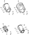
- Fig. 1 to 11 show an embodiment of a medical injection device 1.
- the injection device 1 has an injection device 2.
- a container 3 for the medium to be injected can be designed as a syringe container 3 for receiving a syringe plunger, which is not shown in the drawing.
- To injection device 2 further includes an injection cannula 4, which in the Fig. 2 is visible and in the Fig. 1 is covered by an original cap 5.
- the original protective cap 5 is in the originally delivered state of the injection device 1 after Fig. 1 placed on the injection cannula 4 and axially locked with a cannula-side end of the container 3.
- the injection cannula 4 communicates with the container 3 via a cannula-side mouth and connecting portion 6 of the container 3, which in the sectional view Fig. 5 is visible.
- the mouth and connecting portion 6 is pushed onto a conically tapered mouth end of a glass body of the container 3 and can be connected in addition to this form-fitting and in particular latching.
- the injection cannula 4, which is a metallic cannula, is connected to the mouth section 6 via a plug or cone connection 7.
- the cone connection 7 is designed as a Luer lock connection.
- An inner wall of the mouth portion 6 can in Area of the plug or cone connection 7 locked with an outer wall of a cannula attachment or be positively connected in any other way.
- the injection cannula 4 Apart from the injection cannula 4 all components of the injection device 1 are made of plastic. In principle, the injection cannula 4 can be made of plastic.
- the injection device 1 further has a puncture protection device 8. This is displaceable between a in the Fig. 2 illustrated injection position in which the injection cannula 4 can be exposed, for example, for subcutaneous or intravenous injection of the medium, and one in the Fig. 4 illustrated protection position in which a cannula tip 9 of the injection cannula 4 is sunk in a protective component 10 of the lancing device 8 sunk.
- the anti-puncture device 8 surrounds the mouth portion 6 in the form of a sleeve and has at least two telescopic sleeves.
- the anti-puncture device 8 has a total of three telescopic sleeves 10, 11 and 12, wherein one of these three telescopic sleeves, the protective telescopic sleeve 10, the protective component of the anti-puncture device 8 represents.
- the protective telescopic sleeve 10 is at the same time the outermost of the three telescopic sleeves 10 to 12 of the anti-puncture device 8.
- An innermost of the three telescopic sleeves, the connecting telescopic sleeve 12 is connected via a form-fit adapter 13 with the injection device 2.
- the telescopic sleeve 11 is located as a further telescopic sleeve of the anti-puncture device.
- the telescopic sleeves 10 to 12 are completely superimposed.
- the anti-puncture device 8 covers the cone connection 7 axially, so that it is not accessible from the outside.
- the protective position the telescopic sleeves 10 to 12 are telescoped relative to each other.
- FIGS. 5 and 6 show details of the injection device 1 and in particular details of the puncture protection device. 8
- a safety device in the form of a protective latch assembly 14.
- This has locking rows of teeth 15 with successively along the central telescopic sleeve 11 and the inner connecting telescopic sleeve 12 arranged locking teeth 16.
- Each of the telescopic sleeves 11, 12 has two circumferentially about the longitudinal axis of the injection device opposite each other arranged outer locking rows of teeth 15.
- the two locking rows of teeth 15 of the central telescopic sleeve 11 are relative to the two rows of teeth 15 of the inner connecting telescopic sleeve 12 to 90 ° offset in the circumferential direction about the longitudinal axis of the injection device 1.
- a counter-latching body 17 of the outer protective telescopic sleeve 10 or a counter-latching body 18 engages in the latching teeth 16 (see. Fig. 7 ) of the middle telescoping sleeve 11.
- the ratchet teeth 16 have in the axial longitudinal section of the injection device a sawtooth profile with a preferred direction to ensure a one-way conversion of the telescopic sleeves 10, 11 of the injection position in the telescoping protective position.
- a locking tooth 16 '(see. Fig. 6 ), which corresponds to a maximum telescoped relative position of the associated telescopic sleeves 10, 11, has in axial section an exactly opposite preferred direction to the end Teleskopier ein, ie to define the protective position of the lancing device 8.
- the locking teeth 16 are integrally formed on the respective telescopic sleeve 11, 12.
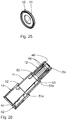
- Fig. 7 shows a groove 20 of one of the groove / spring guide means 19, which is designed in an outer jacket wall of the inner connecting telescopic sleeve 12 as an axial longitudinal groove.
- this groove 20 engages a complementary spring 21, which is executed in an inner wall of the central telescopic sleeve 11 inwardly above.
- the spring 21 of the central telescopic sleeve 11, which cooperates with the groove 20 of the inner telescoping sleeve 12 leading, is formed by the inner ends of the remaining teeth 16 of the central telescopic sleeve 11.
- Another groove / spring guide device 19 is formed by axial longitudinal grooves 22 in the inner jacket wall of the outer protective telescopic sleeve 10 and complementary springs 23, which are designed radially outwardly projecting in the outer jacket wall of the central telescopic sleeve 11.
- two identical tongue and groove guide devices 19 are arranged opposite each other with respect to the longitudinal axis of the injection device 1.
- Each with respect to one of the telescopic sleeves 10 to 12 changes in the circumferential direction about the longitudinal axis of the injection device 1 each in 90 ° increments a locking component of the protective latching arrangement 14 with a component of the groove / spring guide device 19 from.
- the 8 to 11 show instantaneous positions during assembly of the injection device 1.
- the form-fitting adapter 13 is connected by means of latching hooks 24 latching with the container 3 of the injection device 2.
- the latching hooks 24 engage behind a latching collar 25 of the container 3, which is arranged at the transition to the mouth section 6.
- the inner connecting telescopic sleeve 12 is axially connected to the form-fitting adapter 13 via a plurality of locking bodies 26 which are integrally formed on free ends of locking tongues 27 of the form-locking adapter 13.
- the locking tongues 27 extend in the axial direction and are integrally formed on a common support ring 28 of the form-fit adapter 13. Overall, this gives the form-fitting adapter 13 in the form of an axially attachable adapter sleeve.
- a distance between two locking tongues 27 adjacent to one another in the circumferential direction about the longitudinal axis of the injection device 1 and the number of locking tongues 27 is matched to a width and a number of axially extending peripheral ribs 29, which are formed on the outside of the mouth section 6 of the container 3.
- one of the locking tongues 27 is fitted with plug-in form-fitting adapter 13 between two adjacent circumferential ribs 29, so that a rotation of the form-fitting adapter 13 relative to the container 3, namely the mouth and connecting portion 6 of the container 3, is given.
- An inner wall of the inner connecting telescoping sleeve 12 is provided with axial structures, which are not shown in detail in the drawing and with ratcheted on the form-fitting adapter 13 inner connecting telescopic sleeve 12 for a torsion protection of the inner connecting telescoping sleeve 12 provide relative to the form-fitting adapter 13.
- the inner axial structures of the connection telescoping sleeve 12 engage between respectively adjacent latching tongues 27 of the form-fit adapter 13.
- an injection-connection assembly which is designed as injection latching arrangement.
- Latching components of this injection latching arrangement are on the one hand the outer edges of the free ends of the latching hooks 24 of the form-fitting adapter 13 and on the other hand in the injection position this engages behind counter-latching body 17 of the protective telescopic sleeve 10.
- This injection latching arrangement 17, 24 is by notching the counter-locking body 17th from the rear handle to the locking tongues 24 can be overcome. This overcoming can be achieved by a defined pressure on the lancing device 8.
- the injection device 1 is mounted as follows: First, the injection device 2 is in a commercial delivery design, which in the Fig. 8 is reproduced. The anti-puncture device 8 with the sleeves 10 to 12 is pre-assembled in the injection position in which the telescopic sleeves are completely pushed over one another. The form-fitting adapter 13 is then pushed onto the injection device 2 from the cannula side of the injection device 2 with leading latching hooks 24 until the latching hooks 24 latch the latching collar 25 of the container 3 to reach behind (cf. Fig. 9 ).
- the inner connecting telescoping sleeve 12 is pushed in the circumferential direction oriented on the form-fitting adapter 13, that the inner axial structures of the connecting telescopic sleeve 12 between the locking tongues 27 of the form-locking adapter 13 engage.
- a leading stop collar of the connecting telescopic sleeve 12 comes into abutment against a facing end wall of the supporting ring 28 of the positive-locking adapter 13.
- connection telescoping sleeve 12 simultaneously serve as hold-down means for holding the latching tongues 27 between the circumferential ribs 29 of the mouth portion 6 of the injection device 2.
- the injection device 1 is used as follows: First, the protective cap 5 is removed from the injection cannula 4, which is done by a twisting movement (see arrow 30 in the Fig. 1 ). When twisting is secured by the over the outer circumference of the container 3 projecting cross-sectional configuration of the protective telescopic sleeve 10, that the user for twisting the cap 5, the injection device 1 engages outside of the protective telescopic sleeve 10.
- the protective telescopic sleeve 10 has axially extending longitudinal ribs which prevent the protective telescopic sleeve 10 from undesirably rotating between the fingers of the user when the protective cap 5 is being turned off.
- the injection device 1 is then in the ready state, in the Fig. 2 is shown.
- To move the anti-puncture device 8 into the protective position (cf. Fig. 3 to 7 ) is first applied in a pressure range 31, which is marked on the outer protective telescopic sleeve 10, from both sides pressure on the protective telescopic sleeve 10.
- the counter-latching bodies 17 are released from the latching hooks 24 and the outer protective telescoping sleeve 10 can be telescoped axially relative to the telescopic sleeve 11 in the direction of the arrow 32 applied there (see also arrow 33a in FIG Fig. 3 ).
- the counter-latching body 17 rattles over the locking teeth 16 of the protective latching arrangement 14 until the end position of the counter-latching body 17 is reached before the end-side latching tooth 16 'of the central telescopic sleeve 11. Then also telescoped the middle telescopic sleeve 11 relative to the inner connecting telescoping sleeve 12, wherein the counter-locking body 18 of the central telescoping sleeve 11 rattle over the locking teeth 16 of the inner connecting telescoping sleeve 12 until the final position of the counter-latching body 18 in abutment again reaches the end-side locking tooth of the inner connecting telescoping sleeve 12 is.
- the anti-puncture device 8 then lies in the fully telescoped protective position Fig. 4 in front.
- the cannula tip 9 of the injection cannula 4 is arranged completely sunk in the protective telescopic sleeve 10, so that a secure puncture protection is ensured.
- a non-destructive transfer of the lancing device 8, starting from the protective position to Fig. 4 , so that the cannula tip 9 is free again, is not possible for the user due to the one-way characteristic of the associated locking assemblies 14.
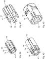
- the puncture protection device 8 of the injection device 33 according to the Fig. 12 to 17 in turn has three telescopic sleeves, namely an outer protective telescopic sleeve 34, whose function of the protective telescopic sleeve 10 of the embodiment of the Fig. 1 to 11 corresponds, a central telescopic sleeve 35, the function of the telescopic sleeve 11 of the embodiment according to the Fig. 1 to 11 corresponds, and an inner connection telescopic component 36, which simultaneously represents a positive connection adapter for positive connection of the lancing device 8 with the injection device 2.
- the connection telescope component 36 thus combines the functions of the inner Telescopic sleeve 12 and the form-fitting adapter 13 of the embodiment according to the Fig. 1 to 11 ,
- connection telescope component 36 is designed as a radially alsrastbarer, C-shaped adapter.
- the connection telescope component 36 is snapped radially onto the mouth section 6 of the container 3, the locking collar 25 of the mouth section 6 being engaged behind the connection telescopic component 36 in a circumferential region for axial securing of the connection telescope component 36.
- inner ribs 37 of the connecting telescope component 36 which in the assembled state with the mouth portion 6 between the peripheral ribs 29th come to rest, made of softer plastic material than the other body of the connecting telescopic component 36.
- the ribs 37 may be integrally formed on the main body of the connecting telescope component 36, for example by multi-component technology, in particular by 2K technology.
- Of the inner ribs 37 is in the Fig. 15 exactly one rib 37 indicated. In fact, several, z. B. five, ribs 37 in the circumferential direction matched to the circumferential distance of the circumferential ribs 29 equidistant before.
- the middle telescopic sleeve 35 (see also Fig. 16 ) is connected to the connection telescope component 36 via a radially acting latching connection.
- the central telescopic sleeve 35 has a spring tongue 38, which engages in a corresponding recess of the connection telescopic component 36.
- the outer protective telescopic sleeve 34 also has a spring tongue 39, which engages behind a corresponding locking receptacle in the middle telescopic sleeve 35 or the connecting telescopic arrangement 36 for latching connection.
- the spring tongue 39 and the latching receptacle assigned in the injection position thus form the injection connection arrangement for the positive fixing of the telescopic protective sleeve 34 on the injection device 2 in the injection position.
- the latching tongue 39 engages behind a latching receptacle 40, which is embodied in the middle telescoping sleeve 35.
- a protective latching arrangement is provided for the latching fixing of the protective telescopic sleeve 34 in the protective position.
- the injection device 41 also has a telescopic anti-puncture device 8, which is basically constructed with a connecting telescopic sleeve 12, a form-locking adapter 13, a central telescopic sleeve 11 and a protective telescopic sleeve 10 as the protective device 8 of the injection device 1. Differences arise in details of the locking connections and the guide designs.
- the locking connections are executed in the injection device 41 as axial locking connections.
- the protective telescopic sleeve 10 is designed in two parts in the lancing device 8 of the injection device 41 and has in addition to the actual telescopic sleeve still an annular cover 42.
- About an outer periphery of the lid 42 is engaged in an inner circumferential groove 43 in an outer end portion of the protective telescopic sleeve 10.
- By an outer circumference of the lid 42 and the inner circumferential groove 43 a Ringschnappthetic between the cover 42 and the protective telescopic sleeve 10 is formed.
- the cover 42 serves to reduce an externally accessible opening width of the protective telescopic sleeve 10 to a through-opening 44 with a reduced diameter compared to the inner diameter of the other protective telescopic sleeve 10.
- the middle telescopic sleeve 11 is inserted from the side of the inner circumferential groove 43 forth in the still without cover present protective telescopic sleeve 10.
- the connecting telescopic sleeve 12 is inserted into the central telescopic sleeve 11 from the same side.
- the lid 42 is locked in the inner circumferential groove 43. From the opposite side of the form-fitting adapter 13 is then inserted into the connecting telescopic sleeve 12.
- the preassembled anti-puncture device can then be pushed onto the injection device 2. This is done until an abutment collar 45 of the form-locking adapter 13 on the locking collar 25 of the injection device 2 (see. Fig. 8 ) is present.
- the connecting telescoping sleeve 12 Upon further pushing the anti-puncture device 8 after the Fig. 18 to 26 to the injection device 2 in the direction of the container 3 to the connecting telescoping sleeve 12 is axially displaced then axially fixed to the latching collar 25 form-fitting adapter 13 until locking hooks 46 which are integrally formed on the connecting telescoping sleeve 12, the latching collar 25 of the mouth portion 6 of the injection device 2 engage behind.
- the protective telescopic sleeve 10 serve as a protective component of the lancing device 8 at the injection device 2 in the injection position.
- the form-fitting adapter 13 of the injection device 41 in turn anti-rotation tongues 47, the locking tongues 27 of the embodiment according to the Fig. 1 to 11 correspond.
- the anti-rotation tongues 47 extend axially and are connected to one another via the support ring 28 of the form-locking adapter 13 of the injection device 41. When mounted, the anti-rotation tongues 47 are each received between two adjacent, axially extending circumferential ribs 29 of the mouth section 6 of the injection device 2.
- a formed on the connecting telescopic sleeve 12 hold-down means This is formed by a total of four inner axial ribs, two of which in axial section Fig. 26 are visible.
- the axial ribs 48 are each offset by 90 ° in the circumferential direction on an inner wall of the connecting telescoping sleeve 12 integrally formed.
- Each of the axial ribs 48 cooperates with a hold-down counterpart on the positive-fit adapter 13 for holding down each anti-twist tongue 47.
- the hold-down counterparts are formed by external axial ribs 49 on the positive-fit adapter 13 (cf. Fig. 21 ).
- the form-fitting adapter 13 is secured to the connecting telescoping sleeve 12 and in each case two adjoining telescopic sleeves 12, 11, 10 are secured against each other in each case by anti-rotation against relative rotation about the longitudinal axis of the anti-puncture device 8.
- This rotation is in turn formed by outer springs 50 on each of the components 13, 12, 11 which cooperate with complementary inner axial grooves 51 in the respectively adjacent, outer adjacent Teleskophülsen 12, 11, 10 rotationally secured.
- the springs 50 simultaneously serve as stops, with axially extending recesses 51a as stops for specifying an axial end position of the connecting telescoping sleeve 12 relative to the form-fitting adapter 13 in the latching connection of the anti-puncture device 8 with the catch collar 25 of the mouth portion 6 via the latching hooks 46th the connection telescoping sleeve 12 cooperate.
- the middle telescoping sleeve 11 and the protective telescoping sleeve 10 have similar, radially acting latching hooks 52.
- the latching hooks 52 are also offset by 90 ° in the circumferential direction.
- the latching hooks 46, 52 of adjacent telescopic sleeves 12, 11, 10 lie exactly above one another.
- the latching hooks 52 of the central telescoping sleeve 11 engage behind complementary recesses 53 in the outside of the latching hooks 46.
- the latching hooks 52 of the protective telescoping sleeve 10 engage corresponding recesses 53 in the outside of the latching hooks 52 of the central telescoping sleeve 11.
- the locking hooks 52 of the central telescopic sleeve 11 on the one hand and the protective telescopic sleeve 10 on the other hand act in the protective position of the anti-puncture device 8 (cf. Fig. 20 and 26 ) with outer circumferential grooves 53 a on the one hand in the connecting telescopic sleeve 12 and on the other hand in the central telescopic sleeve 11 together.
- the latching hooks 52 slide between the respective counter-recesses 53 and the circumferential grooves 53a. So that during the transfer of the telescopic sleeves 11, 10 in the protective position, a uniform force development on the latching hook 52, the telescopic sleeves 12, 11 between the respective counter recesses 53 and the respective circumferential grooves 53 a conically widen.
- the protective telescopic sleeve 10 is designed as a 2K injection molded part.
- the protective telescopic sleeve 10 has a handle portion 55.
- the support body 54 on the one hand and the handle portion 55 on the other hand are designed as different injection-molded components of the 2K component.
- a different number of components can be used in such a multi-component injection-molded part, for example, three or more components of different and especially different hard plastics.
- connection telescoping sleeve 12 may be made of a different plastic for other connection telescopic sleeve 12 other plastic material and the axial ribs 48 may be formed by means of 2K injection molding technology to another support body of the connecting telescoping sleeve 12.
- FIGS. 27 to 35 a further embodiment of an injection device 56 is explained below.
- Components and functions which correspond to those which have already been explained above with reference to the injection devices 1, 33 and 41 and in particular with reference to the injection device 41 bear the same reference numerals and will not be discussed again in detail.
- the connecting telescopic sleeve 12 and the central telescopic sleeve 11 respectively When the protective telescopic sleeve 10 and the central telescopic sleeve 11 are displaced between the injection position and the protective position, the respective latching hooks 52 of the protective telescopic sleeve 10 and the central telescopic sleeve 11 rest on their displacement path between the respective counter-recesses 53 and the respective counter-recesses 53 Circumferential grooves 53a on the latching intermediate stages 57. It results on the path of the two telescopic sleeves 10, 11 between the injection position and the protective position haptic feedback to the user with regard to the already traveled adjustment.
- the injection device 58 is also embodied in four parts with an inner form-fitting adapter 13, a connecting telescopic sleeve 12, a middle telescopic sleeve 11 and an outer protective telescopic sleeve 10.
- latching hooks 46 and 52 of the telescopic sleeves 12, 11 and 10 in the injection device 58 is similar to the injection device 41.
- the telescopic sleeves 11 and 10 each have two opposing, so in the circumferential direction by 180 ° staggered latching hook 52.
- the locking hooks 52 of the central telescopic sleeve 11 relative to the latching hooks 52 of the protective telescoping sleeve 10 offset by 90 ° in the circumferential direction, similar to the concept the counter-locking body and the ratchet teeth in the injection device. 1
- the middle telescopic sleeve 11 is first inserted into the outer protective telescopic sleeve 10 in the direction of arrow 32 until the locking hooks 52 of the outer protective telescopic sleeve 10 engage behind counter recesses 59 of the central telescopic sleeve 11 at the end of axial guideways 60 in a Outside wall of the central telescopic sleeve 11 are executed.
- connection telescoping sleeve 12 is also inserted in the direction of the arrow 32 in the central telescopic sleeve 11. This happens until the latching hooks 52 of the central telescopic sleeve 11 come to lie in recesses 61 of the connecting telescoping sleeve 12, which in turn are embodied at the end of axial guideways 60 in an outer wall of the connecting telescoping sleeve 12.
- the form-fitting adapter 13 again in the direction of the arrow 32, inserted into the connection telescoping sleeve 12 until the latching hooks 46 of the connecting telescoping sleeve 12 engage from the outside in recesses 62 of the form-fitting adapter 13.
- the recesses 62 are in turn executed in axial guideways 60 of the positive connection adapter 13.
- the sleeves 11 and 12 are arranged almost completely in the outer protective telescopic sleeve 10.
- the form-fitting adapter 13 projects with the largest part of an axial extension between the recesses 62 and the abutment collar 45 via the telescoping sleeves 10 to 12 pushed into one another.
- the anti-puncture device 8 When mounting the preassembled anti-puncture device 8 with the injection device 2, the anti-puncture device 8 is pushed with leading positive adapter 13 on the mouth portion 6 of the injection device 2 until the abutment collar 45 abuts the locking collar 25 of the mouth portion 6. Subsequently, the three telescoping telescopic sleeves 10 to 12 are further displaced in the axial direction on the container 3, wherein the locking hooks 46 of the connecting telescoping sleeve 12 disengage from the recesses 62 of the form-locking adapter 13 and first slide along the guideways 60 and then the locking collar 25 for securing the anti-puncture device 8 engage behind the injection device 2. At the same time, hold-down means ensure that the anti-rotation tongues 47 of the positive-fit adapter 13 between adjacent circumferential ribs 29 of the mouth section 6 are held down against the anti-rotation device 8 on the injection device 2 for protection against twisting.
- the anti-puncture device 8 is then prepared in the injection position.
- the Latch hooks of the telescopic sleeves 10, 11 then run axially along the respective guideways 60 of the telescopic sleeves 11 and 12 until the latching hooks 52 of the outer protective telescoping sleeve 10 engage in recesses 63, which are executed at the opposite recesses 59 opposite ends of the guideways 60.
- the protective position continue to move the locking hooks 52 of the central telescopic sleeve 11 in recesses 63, which are executed at the recesses 61 opposite ends in the guideways 60 of the connecting telescoping sleeve 12.
- the telescoped protective position is after Fig. 38 or 43 reached.
Landscapes
- Health & Medical Sciences (AREA)
- Engineering & Computer Science (AREA)
- Heart & Thoracic Surgery (AREA)
- Vascular Medicine (AREA)
- Anesthesiology (AREA)
- Biomedical Technology (AREA)
- Environmental & Geological Engineering (AREA)
- Hematology (AREA)
- Life Sciences & Earth Sciences (AREA)
- Animal Behavior & Ethology (AREA)
- General Health & Medical Sciences (AREA)
- Public Health (AREA)
- Veterinary Medicine (AREA)
- Infusion, Injection, And Reservoir Apparatuses (AREA)
Claims (8)
- Dispositif d'injection à usage médical (1 ; 33 ; 41 ; 56 ; 58) comportant- un moyen d'injection (2), comprenant :-- un récipient (3) destiné au milieu à injecter,-- une canule d'injection (4) communiquant avec le récipient (3),- un moyen anti-piqûre (8) déplaçable entre-- une position d'injection dans laquelle la canule d'injection (4) peut être libérée pour injecter le milieu,-- une position de protection dans laquelle une pointe (9) de la canule d'injection (4) est disposée de manière escamotée dans un composant de protection (10 ; 34) du moyen anti-piqûre (8),- un moyen de sécurité (14 ; 39, 40) destiné à immobiliser de manière sûre le composant de protection (10 ; 34) dans la position de protection ;- un adaptateur à complémentarité de formes (13 ; 36) destiné à raccorder par complémentarité de formes le moyen anti-piqûre (8) au moyen d'injection (2),- le moyen anti-piqûre (8) comprenant au moins deux manchons télescopiques (10 à 12 ; 34 à 36 ; 34, 35, 42), un manchon télescopique de raccordement (12 ; 36 ; 42) étant raccordé au moyen d'injection (2), et un manchon télescopique de protection (10 ; 34) représentant le composant de protection,
caractérisé en ce que- au moins un composant du moyen anti-piqûre (8) se présente sous la forme d'une pièce moulée par injection à plusieurs composants et- au moins un élément structurel moulé par injection à plusieurs composants du moyen anti-piqûre (8) se présente sous la forme d'un manchon extérieur (10) qui comporte au moins une partie de préhension (55) et au moins un corps de support (54), le corps de support (54) d'une part et l'au moins une partie de préhension (55) d'autre part se présentant sous la forme de différents composants moulés par injection de l'élément structurel moulé par injection à plusieurs composants. - Dispositif d'injection selon la revendication 1, caractérisé en ce que le moyen de sécurité (14 ; 39, 40) se présente sous la forme d'un ensemble d'encliquetage de protection destiné à immobiliser par encliquetage le composant de protection (10 ; 34) dans la position de protection.
- Dispositif d'injection selon la revendication 1 ou 2, caractérisé par un ensemble de liaison et d'injection (18, 24 ; 46) destiné à immobiliser par complémentarité de formes le composant de protection (10 ; 34) au niveau du moyen d'injection (2) dans la position d'injection.
- Dispositif d'injection selon la revendication 3, caractérisé en ce que l'ensemble de liaison et d'injection (18, 24) est conçu comme un ensemble d'encliquetage et d'injection destiné à immobiliser par encliquetage le composant de protection (10 ; 34 ; 46) dans la position d'injection.
- Dispositif d'injection selon l'une des revendications 1 à 4, caractérisé en ce qu'au moins un autre manchon télescopique (11 ; 35) du moyen anti-piqûre (8) est disposé entre le manchon télescopique de raccordement (12 ; 36 ; 42) et le manchon télescopique de protection (10 ; 34).
- Dispositif d'injection selon l'une des revendications 1 à 5, caractérisé en ce que l'ensemble d'encliquetage et de protection (14) comporte au moins une rangée (15) de dents d'encliquetage (16 ; 16') qui sont disposées les unes derrière les autres le long d'au moins un des manchons télescopiques (11, 12), dans lesquelles s'engrène un corps d'encliquetage homologue (17, 18) de l'autre manchon télescopique (10, 11), adjacent à ce manchon télescopique (11, 12), du moyen anti-piqûre (8).
- Dispositif d'injection selon l'une des revendications 1 à 6, caractérisé par au moins un moyen de guidage à ressort et rainure (19) destiné à assurer un guidage télescopique et une protection anti-rotation entre deux manchons télescopiques adjacents (10 à 12 ; 34 à 36 ; 34, 35,42).
- Dispositif d'injection selon l'une des revendications 1 à 7, caractérisé en ce que le moyen anti-piqûre (8) comporte :- au moins un élément de liaison par complémentarité de formes (37) reçu entre deux nervures circonférentielles (29) adjacentes s'étendant axialement d'une partie de raccordement et d'embouchure (6) du dispositif d'injection (2),- l'élément de liaison par complémentarité de formes (37) étant formé au niveau d'un corps de support d'élément de liaison par complémentarité de formes (36),- le corps de support d'élément de liaison par complémentarité de formes (36) d'une part et l'au moins un élément de liaison par complémentarité de formes (37) d'autre part se présentant sous la forme de différents composants moulés par injection de l'élément structurel (36) moulé par injection à plusieurs composants.
Applications Claiming Priority (1)
| Application Number | Priority Date | Filing Date | Title |
|---|---|---|---|
| DE102013214429.6A DE102013214429A1 (de) | 2013-07-24 | 2013-07-24 | Medizinische Injektionsvorrichtung |
Publications (2)
| Publication Number | Publication Date |
|---|---|
| EP2829296A1 EP2829296A1 (fr) | 2015-01-28 |
| EP2829296B1 true EP2829296B1 (fr) | 2018-08-15 |
Family
ID=51176899
Family Applications (1)
| Application Number | Title | Priority Date | Filing Date |
|---|---|---|---|
| EP14173845.0A Active EP2829296B1 (fr) | 2013-07-24 | 2014-06-25 | Dispositif médical d'injection |
Country Status (5)
| Country | Link |
|---|---|
| US (1) | US10493214B2 (fr) |
| EP (1) | EP2829296B1 (fr) |
| DE (1) | DE102013214429A1 (fr) |
| DK (1) | DK2829296T5 (fr) |
| ES (1) | ES2691071T3 (fr) |
Families Citing this family (9)
| Publication number | Priority date | Publication date | Assignee | Title |
|---|---|---|---|---|
| JP6296840B2 (ja) * | 2014-03-11 | 2018-03-20 | テルモ株式会社 | 液体投与具 |
| WO2015200712A1 (fr) * | 2014-06-25 | 2015-12-30 | Massachusetts Institute Of Technology | Capteur optique permettant un diagnostic et une identification de tissus de pointe d'aiguille |
| GB2529621B (en) | 2014-08-21 | 2016-12-07 | Owen Mumford Ltd | Safety syringe |
| CN107427647A (zh) * | 2015-03-27 | 2017-12-01 | 泰尔茂株式会社 | 注射针组装体及药剂注射装置 |
| CN115474468B (zh) * | 2016-10-14 | 2024-04-05 | 创科无线普通合伙 | 线式修剪机 |
| US11759578B2 (en) | 2017-11-03 | 2023-09-19 | Sanofi | Needle shroud assembly and drug delivery device |
| CN114423478B (zh) * | 2019-09-17 | 2023-12-08 | 碧迪股份有限公司 | 被动式安全装置、包括该安全装置的注射装置和用来制造所述注射装置的方法 |
| WO2024188695A1 (fr) * | 2023-03-14 | 2024-09-19 | Shl Medical Ag | Dispositif d'extension de diamètre pour dispositif d'administration de médicament |
| EP4680306A1 (fr) * | 2023-03-14 | 2026-01-21 | SHL Medical AG | Dispositif d'administration de médicament |
Citations (2)
| Publication number | Priority date | Publication date | Assignee | Title |
|---|---|---|---|---|
| US4923447A (en) * | 1989-02-17 | 1990-05-08 | Morgan Michael W | Syringe assembly |
| EP2578255A1 (fr) * | 2011-10-06 | 2013-04-10 | Sanofi-Aventis Deutschland GmbH | Dispositif de sécurité d'aiguille |
Family Cites Families (51)
| Publication number | Priority date | Publication date | Assignee | Title |
|---|---|---|---|---|
| US139489A (en) | 1873-06-03 | Improvement in blast-furnaces | ||
| US944397A (en) | 1909-05-10 | 1909-12-28 | William Williams | Sterilizing attachment for the mouthpieces of speaking instruments. |
| US4573976A (en) * | 1984-05-24 | 1986-03-04 | Dolores A. Smith | Shielded needle |
| DE3767668D1 (de) * | 1986-11-19 | 1991-02-28 | Sterimatic Holdings Ltd | Injektionsvorrichtungen. |
| GB8630016D0 (en) * | 1986-12-16 | 1987-01-28 | Id Tech Ltd | Dental injection device |
| US4795432A (en) * | 1987-02-19 | 1989-01-03 | Karczmer Claude M | Shield assembly for hypodermic injection devices |
| US4838871A (en) | 1987-07-17 | 1989-06-13 | Luther Ronald B | Needle guard, and assembly |
| US4927416A (en) * | 1987-12-02 | 1990-05-22 | National Medical Device Corporation | User-protective hypodermic syringe holder |
| US5067945A (en) * | 1988-03-01 | 1991-11-26 | Ryan Medical, Inc. | Safety needled medical devices capable of one-handed manipulation |
| US4897083A (en) * | 1988-05-09 | 1990-01-30 | Martell Michael D | Syringe needle guard |
| US4944397A (en) | 1988-05-23 | 1990-07-31 | University Medical Center, Inc. | Disposable covered needle for syringe |
| US4892521A (en) * | 1988-08-03 | 1990-01-09 | Lincoln Mills, Inc. | Protective cover for hypodermic needle |
| AU7045591A (en) | 1989-12-21 | 1991-07-24 | Andrew William Steer | Needle protector |
| CH685979A5 (de) * | 1990-03-13 | 1995-11-30 | Rutz Hans Consulting Ag | Verfahren zur Entsorgung von Einweg-Injektionsmaterial sowie Einweg-Injektionsspritzen zur Durchfuhrung des Verfahrens. |
| US4982842A (en) | 1990-06-04 | 1991-01-08 | Concord/Portex | Safety needle container |
| US5116325A (en) | 1990-06-06 | 1992-05-26 | Paterson Donald W | Needle assembly |
| US5139489A (en) | 1991-01-07 | 1992-08-18 | Smiths Industries Medical Systems, Inc. | Needle protection device |
| US5232454A (en) | 1990-08-01 | 1993-08-03 | Smiths Industries Medical Systems, Inc. | Safety needle container |
| US5232455A (en) | 1991-01-07 | 1993-08-03 | Smiths Industries Medical Systems, Inc. | Syringe with protective housing |
| US5277311A (en) | 1991-12-20 | 1994-01-11 | Smiths Industries Medical Systems, Inc. | Needle assembly holder with rotatable safety sheath member and method of effecting proper alignment of a cannula using such needle assembly holder |
| GB9200219D0 (en) * | 1992-01-07 | 1992-02-26 | Medimech Int Ltd | Automatic injectors |
| US5242416A (en) * | 1992-01-09 | 1993-09-07 | Hutson Clifford L | Shield assembly for needle syringes |
| JPH08505543A (ja) * | 1992-11-19 | 1996-06-18 | テブロ ソシエテ アノニム | 予充填注射器用の使い捨て自動注射装置 |
| US5423765A (en) | 1993-05-06 | 1995-06-13 | Smiths Industries Medical Systems, Inc. | Removable safety needle sheath |
| US5312367A (en) | 1993-05-20 | 1994-05-17 | Nathan Rasa N | Needle cover assembly for syringes |
| US5342322A (en) | 1993-05-20 | 1994-08-30 | Rasa N. Nathan | Needle cover assembly for syringes |
| JPH08509153A (ja) * | 1994-02-14 | 1996-10-01 | メディコル ホールディング ソシエテ アノニム | 注射筒のインジェクタモジュールと、このインジェクタモジュールを装着した充填済み注射筒 |
| US5498243A (en) * | 1995-01-31 | 1996-03-12 | Unique Management Enterprises, Inc. | Apparatus for shielding a syringe needle |
| IT1268833B1 (it) | 1994-06-23 | 1997-03-13 | Cgm Spa | Dispositivo di protezione dell'ago per siringa per penetrazione nel corpo |
| US5643219A (en) | 1994-09-23 | 1997-07-01 | Burns; James A. | Shielded needle assembly |
| CA2157999C (fr) | 1994-09-23 | 1999-08-03 | Robert B. Odell | Dispositif protecteur a rotation manuelle pour element de percage |
| US5445619A (en) | 1994-09-23 | 1995-08-29 | Becton, Dickinson And Company | Shielded needle assembly |
| US5595566A (en) * | 1995-01-31 | 1997-01-21 | Unique Management Enterprises, Inc. | Apparatus for shielding a syringe needle |
| US5584816A (en) | 1995-05-25 | 1996-12-17 | Becton, Dickinson And Company | Hardpack shield for a pivoting needle guard |
| US5632732A (en) | 1996-09-11 | 1997-05-27 | Becton, Dickinson And Company | Needle assembly having single handedly activated shield |
| CA2221849C (fr) | 1997-03-06 | 2004-04-27 | Sandor Szabo | Protecteur d'aiguille se liberant d'une seule main |
| US6036675A (en) * | 1999-02-03 | 2000-03-14 | Specialized Health Products, Inc. | Safety sterile cartride unit apparatus and methods |
| FR2835753B1 (fr) * | 2002-02-11 | 2004-10-29 | Plastef Investissements | Dispositif de support de securite pour une seringue et ensemble d'un tel dispositif et d'une seringue |
| US6752783B2 (en) * | 2002-07-10 | 2004-06-22 | Ming-Kan Hung | Safety device for syringe |
| FR2842429A1 (fr) | 2002-07-19 | 2004-01-23 | Biofront | Dispositif de protection pour un element invasif du type aiguille |
| CN100364481C (zh) | 2002-12-16 | 2008-01-30 | 贝克顿·迪金森公司 | 安全针组件 |
| AT413947B (de) | 2003-01-27 | 2006-07-15 | Greiner Bio One Gmbh | Medizinische baugruppe sowie eine schutzvorrichtung, ein einstichelement und eine handhabungsvorrichtung für diese baugruppe |
| US6997902B2 (en) * | 2003-11-13 | 2006-02-14 | David L. Thorne | Safety shield for medical needles |
| US8226576B2 (en) | 2004-02-25 | 2012-07-24 | Becton, Dickinson And Company | Safety blood collection holder |
| US7462168B2 (en) * | 2007-01-23 | 2008-12-09 | Becton, Dickinson And Company | Safety pen needle with passive safety shield system |
| US7540858B2 (en) * | 2007-01-23 | 2009-06-02 | Becton, Dickinson And Company | Retracting safety pen needle |
| US7828768B2 (en) * | 2008-04-09 | 2010-11-09 | Southern Taiwan University | Disposable syringe after one time usage |
| EP2578256A1 (fr) * | 2011-10-06 | 2013-04-10 | Sanofi-Aventis Deutschland GmbH | Dispositif de sécurité d'aiguille |
| US9278179B2 (en) * | 2012-06-20 | 2016-03-08 | Safety Syringes, Inc. | Contact trigger release needle guard with elastic spring |
| WO2014048298A1 (fr) * | 2012-09-28 | 2014-04-03 | Shanghai Sol-Millennium Medical Products Co., Ltd. | Dispositif de protection d'aiguille du type à manchon coulissant et seringue de sécurité |
| WO2014164823A1 (fr) * | 2013-03-11 | 2014-10-09 | Auerbach, Judith | Système de sécurité pour un dispositif de retenue d'aiguille |
-
2013
- 2013-07-24 DE DE102013214429.6A patent/DE102013214429A1/de not_active Withdrawn
-
2014
- 2014-06-25 EP EP14173845.0A patent/EP2829296B1/fr active Active
- 2014-06-25 DK DK14173845.0T patent/DK2829296T5/en active
- 2014-06-25 ES ES14173845.0T patent/ES2691071T3/es active Active
- 2014-07-24 US US14/339,812 patent/US10493214B2/en not_active Expired - Fee Related
Patent Citations (2)
| Publication number | Priority date | Publication date | Assignee | Title |
|---|---|---|---|---|
| US4923447A (en) * | 1989-02-17 | 1990-05-08 | Morgan Michael W | Syringe assembly |
| EP2578255A1 (fr) * | 2011-10-06 | 2013-04-10 | Sanofi-Aventis Deutschland GmbH | Dispositif de sécurité d'aiguille |
Also Published As
| Publication number | Publication date |
|---|---|
| EP2829296A1 (fr) | 2015-01-28 |
| DE102013214429A1 (de) | 2015-02-19 |
| ES2691071T3 (es) | 2018-11-23 |
| DK2829296T5 (en) | 2019-02-11 |
| US20150032061A1 (en) | 2015-01-29 |
| US10493214B2 (en) | 2019-12-03 |
| DK2829296T3 (en) | 2018-12-10 |
Similar Documents
| Publication | Publication Date | Title |
|---|---|---|
| EP2829296B1 (fr) | Dispositif médical d'injection | |
| EP2037988B1 (fr) | Seringue | |
| EP2063939B1 (fr) | Dispositif de protection d'aiguille à position de protection bloquée | |
| DE68908975T2 (de) | Mit einer Nadelhülse verbundene Spritze und Verfahren zur Herstellung. | |
| EP3325054B1 (fr) | Dispositif de sécurité pour seringue | |
| EP2063937B1 (fr) | Dispositif de protection d'aiguille présentant une position de protection bloquée | |
| EP3250171B1 (fr) | Dispositif pour transférer un liquide entre un réservoir et au moins un autre récipient d'utilisation | |
| EP2829295B1 (fr) | Dispositif d'injection médicale | |
| WO2013083279A2 (fr) | Obturateur, notamment obturateur de seringue pour l'obturation étanche d'une ouverture distale d'un corps de seringue | |
| WO2012116790A1 (fr) | Bouchon pour seringue et procédé de fabrication | |
| EP3313482B1 (fr) | Dispositif de sûreté en plusieurs parties pour une seringue | |
| EP3244962B1 (fr) | Dispositif de raccordement pour système de ligne de fluide médical | |
| DE102007009340A1 (de) | Nadelschutzvorrichtung mit integrierter Nadelträgerentfernungsvorrichtung zum Entfernen eines Nadelträgers von einem Injektionsgerät | |
| WO2009046560A9 (fr) | Dispositif de sécurité pour la canule d'un instrument invasif | |
| DE102015201288B4 (de) | Hohlnadel-Baugruppe | |
| DE202004011516U1 (de) | Spritze | |
| EP3250172B1 (fr) | Dispositif de transfert d'un liquide entre un récipient de stockage et au moins récipient d'utilisation | |
| DE3842107C2 (fr) | ||
| EP1154812B1 (fr) | Dispositif d'injection | |
| DE602004004789T2 (de) | Einwegspritze mit zurückziehbarer Nadel | |
| AT12002U1 (de) | Karpulenspritze | |
| WO2024100128A1 (fr) | Bouchon multi-composant pour seringue médicale et seringue médicale | |
| DE202011107268U1 (de) | Sicherheits-Injektionsspritze |
Legal Events
| Date | Code | Title | Description |
|---|---|---|---|
| 17P | Request for examination filed |
Effective date: 20140625 |
|
| AK | Designated contracting states |
Kind code of ref document: A1 Designated state(s): AL AT BE BG CH CY CZ DE DK EE ES FI FR GB GR HR HU IE IS IT LI LT LU LV MC MK MT NL NO PL PT RO RS SE SI SK SM TR |
|
| AX | Request for extension of the european patent |
Extension state: BA ME |
|
| PUAI | Public reference made under article 153(3) epc to a published international application that has entered the european phase |
Free format text: ORIGINAL CODE: 0009012 |
|
| R17P | Request for examination filed (corrected) |
Effective date: 20150511 |
|
| RBV | Designated contracting states (corrected) |
Designated state(s): AL AT BE BG CH CY CZ DE DK EE ES FI FR GB GR HR HU IE IS IT LI LT LU LV MC MK MT NL NO PL PT RO RS SE SI SK SM TR |
|
| STAA | Information on the status of an ep patent application or granted ep patent |
Free format text: STATUS: EXAMINATION IS IN PROGRESS |
|
| 17Q | First examination report despatched |
Effective date: 20170920 |
|
| GRAP | Despatch of communication of intention to grant a patent |
Free format text: ORIGINAL CODE: EPIDOSNIGR1 |
|
| STAA | Information on the status of an ep patent application or granted ep patent |
Free format text: STATUS: GRANT OF PATENT IS INTENDED |
|
| INTG | Intention to grant announced |
Effective date: 20180403 |
|
| INTG | Intention to grant announced |
Effective date: 20180403 |
|
| GRAS | Grant fee paid |
Free format text: ORIGINAL CODE: EPIDOSNIGR3 |
|
| GRAA | (expected) grant |
Free format text: ORIGINAL CODE: 0009210 |
|
| STAA | Information on the status of an ep patent application or granted ep patent |
Free format text: STATUS: THE PATENT HAS BEEN GRANTED |
|
| AK | Designated contracting states |
Kind code of ref document: B1 Designated state(s): AL AT BE BG CH CY CZ DE DK EE ES FI FR GB GR HR HU IE IS IT LI LT LU LV MC MK MT NL NO PL PT RO RS SE SI SK SM TR |
|
| REG | Reference to a national code |
Ref country code: CH Ref legal event code: EP Ref country code: GB Ref legal event code: FG4D Free format text: NOT ENGLISH Ref country code: AT Ref legal event code: REF Ref document number: 1029031 Country of ref document: AT Kind code of ref document: T Effective date: 20180815 |
|
| REG | Reference to a national code |
Ref country code: IE Ref legal event code: FG4D Free format text: LANGUAGE OF EP DOCUMENT: GERMAN |
|
| REG | Reference to a national code |
Ref country code: DE Ref legal event code: R096 Ref document number: 502014009187 Country of ref document: DE |
|
| REG | Reference to a national code |
Ref country code: NL Ref legal event code: FP |
|
| REG | Reference to a national code |
Ref country code: ES Ref legal event code: FG2A Ref document number: 2691071 Country of ref document: ES Kind code of ref document: T3 Effective date: 20181123 |
|
| REG | Reference to a national code |
Ref country code: SE Ref legal event code: TRGR |
|
| REG | Reference to a national code |
Ref country code: DK Ref legal event code: T3 Effective date: 20181203 |
|
| REG | Reference to a national code |
Ref country code: NO Ref legal event code: T2 Effective date: 20180815 |
|
| REG | Reference to a national code |
Ref country code: LT Ref legal event code: MG4D |
|
| PG25 | Lapsed in a contracting state [announced via postgrant information from national office to epo] |
Ref country code: BG Free format text: LAPSE BECAUSE OF FAILURE TO SUBMIT A TRANSLATION OF THE DESCRIPTION OR TO PAY THE FEE WITHIN THE PRESCRIBED TIME-LIMIT Effective date: 20181115 Ref country code: RS Free format text: LAPSE BECAUSE OF FAILURE TO SUBMIT A TRANSLATION OF THE DESCRIPTION OR TO PAY THE FEE WITHIN THE PRESCRIBED TIME-LIMIT Effective date: 20180815 Ref country code: GR Free format text: LAPSE BECAUSE OF FAILURE TO SUBMIT A TRANSLATION OF THE DESCRIPTION OR TO PAY THE FEE WITHIN THE PRESCRIBED TIME-LIMIT Effective date: 20181116 Ref country code: LT Free format text: LAPSE BECAUSE OF FAILURE TO SUBMIT A TRANSLATION OF THE DESCRIPTION OR TO PAY THE FEE WITHIN THE PRESCRIBED TIME-LIMIT Effective date: 20180815 Ref country code: IS Free format text: LAPSE BECAUSE OF FAILURE TO SUBMIT A TRANSLATION OF THE DESCRIPTION OR TO PAY THE FEE WITHIN THE PRESCRIBED TIME-LIMIT Effective date: 20181215 |
|
| REG | Reference to a national code |
Ref country code: DK Ref legal event code: T5 Effective date: 20190206 |
|
| PG25 | Lapsed in a contracting state [announced via postgrant information from national office to epo] |
Ref country code: HR Free format text: LAPSE BECAUSE OF FAILURE TO SUBMIT A TRANSLATION OF THE DESCRIPTION OR TO PAY THE FEE WITHIN THE PRESCRIBED TIME-LIMIT Effective date: 20180815 Ref country code: LV Free format text: LAPSE BECAUSE OF FAILURE TO SUBMIT A TRANSLATION OF THE DESCRIPTION OR TO PAY THE FEE WITHIN THE PRESCRIBED TIME-LIMIT Effective date: 20180815 Ref country code: AL Free format text: LAPSE BECAUSE OF FAILURE TO SUBMIT A TRANSLATION OF THE DESCRIPTION OR TO PAY THE FEE WITHIN THE PRESCRIBED TIME-LIMIT Effective date: 20180815 |
|
| PG25 | Lapsed in a contracting state [announced via postgrant information from national office to epo] |
Ref country code: CZ Free format text: LAPSE BECAUSE OF FAILURE TO SUBMIT A TRANSLATION OF THE DESCRIPTION OR TO PAY THE FEE WITHIN THE PRESCRIBED TIME-LIMIT Effective date: 20180815 Ref country code: RO Free format text: LAPSE BECAUSE OF FAILURE TO SUBMIT A TRANSLATION OF THE DESCRIPTION OR TO PAY THE FEE WITHIN THE PRESCRIBED TIME-LIMIT Effective date: 20180815 Ref country code: EE Free format text: LAPSE BECAUSE OF FAILURE TO SUBMIT A TRANSLATION OF THE DESCRIPTION OR TO PAY THE FEE WITHIN THE PRESCRIBED TIME-LIMIT Effective date: 20180815 Ref country code: PL Free format text: LAPSE BECAUSE OF FAILURE TO SUBMIT A TRANSLATION OF THE DESCRIPTION OR TO PAY THE FEE WITHIN THE PRESCRIBED TIME-LIMIT Effective date: 20180815 |
|
| REG | Reference to a national code |
Ref country code: DE Ref legal event code: R097 Ref document number: 502014009187 Country of ref document: DE |
|
| PG25 | Lapsed in a contracting state [announced via postgrant information from national office to epo] |
Ref country code: SK Free format text: LAPSE BECAUSE OF FAILURE TO SUBMIT A TRANSLATION OF THE DESCRIPTION OR TO PAY THE FEE WITHIN THE PRESCRIBED TIME-LIMIT Effective date: 20180815 Ref country code: SM Free format text: LAPSE BECAUSE OF FAILURE TO SUBMIT A TRANSLATION OF THE DESCRIPTION OR TO PAY THE FEE WITHIN THE PRESCRIBED TIME-LIMIT Effective date: 20180815 |
|
| PLBE | No opposition filed within time limit |
Free format text: ORIGINAL CODE: 0009261 |
|
| STAA | Information on the status of an ep patent application or granted ep patent |
Free format text: STATUS: NO OPPOSITION FILED WITHIN TIME LIMIT |
|
| 26N | No opposition filed |
Effective date: 20190516 |
|
| PG25 | Lapsed in a contracting state [announced via postgrant information from national office to epo] |
Ref country code: SI Free format text: LAPSE BECAUSE OF FAILURE TO SUBMIT A TRANSLATION OF THE DESCRIPTION OR TO PAY THE FEE WITHIN THE PRESCRIBED TIME-LIMIT Effective date: 20180815 |
|
| PG25 | Lapsed in a contracting state [announced via postgrant information from national office to epo] |
Ref country code: MC Free format text: LAPSE BECAUSE OF FAILURE TO SUBMIT A TRANSLATION OF THE DESCRIPTION OR TO PAY THE FEE WITHIN THE PRESCRIBED TIME-LIMIT Effective date: 20180815 |
|
| REG | Reference to a national code |
Ref country code: BE Ref legal event code: MM Effective date: 20190630 |
|
| PG25 | Lapsed in a contracting state [announced via postgrant information from national office to epo] |
Ref country code: TR Free format text: LAPSE BECAUSE OF FAILURE TO SUBMIT A TRANSLATION OF THE DESCRIPTION OR TO PAY THE FEE WITHIN THE PRESCRIBED TIME-LIMIT Effective date: 20180815 |
|
| PG25 | Lapsed in a contracting state [announced via postgrant information from national office to epo] |
Ref country code: BE Free format text: LAPSE BECAUSE OF NON-PAYMENT OF DUE FEES Effective date: 20190630 Ref country code: LU Free format text: LAPSE BECAUSE OF NON-PAYMENT OF DUE FEES Effective date: 20190625 |
|
| PG25 | Lapsed in a contracting state [announced via postgrant information from national office to epo] |
Ref country code: PT Free format text: LAPSE BECAUSE OF FAILURE TO SUBMIT A TRANSLATION OF THE DESCRIPTION OR TO PAY THE FEE WITHIN THE PRESCRIBED TIME-LIMIT Effective date: 20181215 |
|
| PG25 | Lapsed in a contracting state [announced via postgrant information from national office to epo] |
Ref country code: CY Free format text: LAPSE BECAUSE OF FAILURE TO SUBMIT A TRANSLATION OF THE DESCRIPTION OR TO PAY THE FEE WITHIN THE PRESCRIBED TIME-LIMIT Effective date: 20180815 |
|
| PG25 | Lapsed in a contracting state [announced via postgrant information from national office to epo] |
Ref country code: HU Free format text: LAPSE BECAUSE OF FAILURE TO SUBMIT A TRANSLATION OF THE DESCRIPTION OR TO PAY THE FEE WITHIN THE PRESCRIBED TIME-LIMIT; INVALID AB INITIO Effective date: 20140625 Ref country code: MT Free format text: LAPSE BECAUSE OF FAILURE TO SUBMIT A TRANSLATION OF THE DESCRIPTION OR TO PAY THE FEE WITHIN THE PRESCRIBED TIME-LIMIT Effective date: 20180815 |
|
| PG25 | Lapsed in a contracting state [announced via postgrant information from national office to epo] |
Ref country code: MK Free format text: LAPSE BECAUSE OF FAILURE TO SUBMIT A TRANSLATION OF THE DESCRIPTION OR TO PAY THE FEE WITHIN THE PRESCRIBED TIME-LIMIT Effective date: 20180815 |
|
| PGFP | Annual fee paid to national office [announced via postgrant information from national office to epo] |
Ref country code: SE Payment date: 20220623 Year of fee payment: 9 Ref country code: NO Payment date: 20220621 Year of fee payment: 9 Ref country code: NL Payment date: 20220621 Year of fee payment: 9 Ref country code: IE Payment date: 20220616 Year of fee payment: 9 Ref country code: GB Payment date: 20220623 Year of fee payment: 9 Ref country code: DK Payment date: 20220623 Year of fee payment: 9 Ref country code: DE Payment date: 20220617 Year of fee payment: 9 |
|
| PGFP | Annual fee paid to national office [announced via postgrant information from national office to epo] |
Ref country code: FI Payment date: 20220617 Year of fee payment: 9 Ref country code: AT Payment date: 20220512 Year of fee payment: 9 |
|
| PGFP | Annual fee paid to national office [announced via postgrant information from national office to epo] |
Ref country code: FR Payment date: 20220622 Year of fee payment: 9 |
|
| PGFP | Annual fee paid to national office [announced via postgrant information from national office to epo] |
Ref country code: IT Payment date: 20220630 Year of fee payment: 9 Ref country code: ES Payment date: 20220719 Year of fee payment: 9 |
|
| PGFP | Annual fee paid to national office [announced via postgrant information from national office to epo] |
Ref country code: CH Payment date: 20220702 Year of fee payment: 9 |
|
| REG | Reference to a national code |
Ref country code: DE Ref legal event code: R119 Ref document number: 502014009187 Country of ref document: DE |
|
| REG | Reference to a national code |
Ref country code: NO Ref legal event code: MMEP Ref country code: DK Ref legal event code: EBP Effective date: 20230630 |
|
| REG | Reference to a national code |
Ref country code: SE Ref legal event code: EUG |
|
| PG25 | Lapsed in a contracting state [announced via postgrant information from national office to epo] |
Ref country code: FI Free format text: LAPSE BECAUSE OF NON-PAYMENT OF DUE FEES Effective date: 20230625 |
|
| REG | Reference to a national code |
Ref country code: CH Ref legal event code: PL |
|
| REG | Reference to a national code |
Ref country code: NL Ref legal event code: MM Effective date: 20230701 |
|
| REG | Reference to a national code |
Ref country code: AT Ref legal event code: MM01 Ref document number: 1029031 Country of ref document: AT Kind code of ref document: T Effective date: 20230625 |
|
| GBPC | Gb: european patent ceased through non-payment of renewal fee |
Effective date: 20230625 |
|
| REG | Reference to a national code |
Ref country code: IE Ref legal event code: MM4A |
|
| PG25 | Lapsed in a contracting state [announced via postgrant information from national office to epo] |
Ref country code: NL Free format text: LAPSE BECAUSE OF NON-PAYMENT OF DUE FEES Effective date: 20230701 |
|
| PG25 | Lapsed in a contracting state [announced via postgrant information from national office to epo] |
Ref country code: IE Free format text: LAPSE BECAUSE OF NON-PAYMENT OF DUE FEES Effective date: 20230625 |
|
| PG25 | Lapsed in a contracting state [announced via postgrant information from national office to epo] |
Ref country code: AT Free format text: LAPSE BECAUSE OF NON-PAYMENT OF DUE FEES Effective date: 20230625 |
|
| PG25 | Lapsed in a contracting state [announced via postgrant information from national office to epo] |
Ref country code: IE Free format text: LAPSE BECAUSE OF NON-PAYMENT OF DUE FEES Effective date: 20230625 Ref country code: AT Free format text: LAPSE BECAUSE OF NON-PAYMENT OF DUE FEES Effective date: 20230625 Ref country code: DE Free format text: LAPSE BECAUSE OF NON-PAYMENT OF DUE FEES Effective date: 20240103 Ref country code: GB Free format text: LAPSE BECAUSE OF NON-PAYMENT OF DUE FEES Effective date: 20230625 Ref country code: CH Free format text: LAPSE BECAUSE OF NON-PAYMENT OF DUE FEES Effective date: 20230630 |
|
| PG25 | Lapsed in a contracting state [announced via postgrant information from national office to epo] |
Ref country code: SE Free format text: LAPSE BECAUSE OF NON-PAYMENT OF DUE FEES Effective date: 20230626 Ref country code: NO Free format text: LAPSE BECAUSE OF NON-PAYMENT OF DUE FEES Effective date: 20230630 Ref country code: FR Free format text: LAPSE BECAUSE OF NON-PAYMENT OF DUE FEES Effective date: 20230630 |
|
| PG25 | Lapsed in a contracting state [announced via postgrant information from national office to epo] |
Ref country code: DK Free format text: LAPSE BECAUSE OF NON-PAYMENT OF DUE FEES Effective date: 20230630 |
|
| PG25 | Lapsed in a contracting state [announced via postgrant information from national office to epo] |
Ref country code: IT Free format text: LAPSE BECAUSE OF NON-PAYMENT OF DUE FEES Effective date: 20230625 Ref country code: DK Free format text: LAPSE BECAUSE OF NON-PAYMENT OF DUE FEES Effective date: 20230630 |
|
| REG | Reference to a national code |
Ref country code: ES Ref legal event code: FD2A Effective date: 20240802 |
|
| PG25 | Lapsed in a contracting state [announced via postgrant information from national office to epo] |
Ref country code: ES Free format text: LAPSE BECAUSE OF NON-PAYMENT OF DUE FEES Effective date: 20230626 |
|
| PG25 | Lapsed in a contracting state [announced via postgrant information from national office to epo] |
Ref country code: ES Free format text: LAPSE BECAUSE OF NON-PAYMENT OF DUE FEES Effective date: 20230626 |