EP2829288A1 - Verbindungsvorrichtung und vorrichtung zur trennung von blutkomponenten - Google Patents
Verbindungsvorrichtung und vorrichtung zur trennung von blutkomponenten Download PDFInfo
- Publication number
- EP2829288A1 EP2829288A1 EP13765200.4A EP13765200A EP2829288A1 EP 2829288 A1 EP2829288 A1 EP 2829288A1 EP 13765200 A EP13765200 A EP 13765200A EP 2829288 A1 EP2829288 A1 EP 2829288A1
- Authority
- EP
- European Patent Office
- Prior art keywords
- portions
- connection device
- engagement
- syringe
- hollow needle
- Prior art date
- Legal status (The legal status is an assumption and is not a legal conclusion. Google has not performed a legal analysis and makes no representation as to the accuracy of the status listed.)
- Granted
Links
- 238000000926 separation method Methods 0.000 title claims abstract description 35
- 239000012503 blood component Substances 0.000 title claims abstract description 20
- 230000007246 mechanism Effects 0.000 claims description 31
- 230000004048 modification Effects 0.000 description 41
- 238000012986 modification Methods 0.000 description 41
- 210000004369 blood Anatomy 0.000 description 33
- 239000008280 blood Substances 0.000 description 33
- 210000004623 platelet-rich plasma Anatomy 0.000 description 33
- 210000001772 blood platelet Anatomy 0.000 description 23
- 238000005119 centrifugation Methods 0.000 description 19
- 210000000078 claw Anatomy 0.000 description 19
- 210000002381 plasma Anatomy 0.000 description 18
- 230000003014 reinforcing effect Effects 0.000 description 16
- 210000003743 erythrocyte Anatomy 0.000 description 13
- 239000006228 supernatant Substances 0.000 description 12
- 239000004743 Polypropylene Substances 0.000 description 9
- 238000003780 insertion Methods 0.000 description 9
- 230000037431 insertion Effects 0.000 description 9
- -1 polypropylene Polymers 0.000 description 9
- 229920001155 polypropylene Polymers 0.000 description 9
- 239000011347 resin Substances 0.000 description 9
- 229920005989 resin Polymers 0.000 description 9
- 210000000265 leukocyte Anatomy 0.000 description 8
- 230000005489 elastic deformation Effects 0.000 description 7
- 239000000306 component Substances 0.000 description 5
- 230000000694 effects Effects 0.000 description 5
- 238000000034 method Methods 0.000 description 4
- 210000000601 blood cell Anatomy 0.000 description 3
- 238000004519 manufacturing process Methods 0.000 description 3
- 239000000463 material Substances 0.000 description 3
- 238000011069 regeneration method Methods 0.000 description 3
- 229920001971 elastomer Polymers 0.000 description 2
- 239000000806 elastomer Substances 0.000 description 2
- 239000003102 growth factor Substances 0.000 description 2
- 238000003825 pressing Methods 0.000 description 2
- 239000002994 raw material Substances 0.000 description 2
- 230000008929 regeneration Effects 0.000 description 2
- 102000004887 Transforming Growth Factor beta Human genes 0.000 description 1
- 108090001012 Transforming Growth Factor beta Proteins 0.000 description 1
- 206010052428 Wound Diseases 0.000 description 1
- 208000027418 Wounds and injury Diseases 0.000 description 1
- 239000010836 blood and blood product Substances 0.000 description 1
- 229940125691 blood product Drugs 0.000 description 1
- 238000007599 discharging Methods 0.000 description 1
- 239000003814 drug Substances 0.000 description 1
- 239000011521 glass Substances 0.000 description 1
- 239000008187 granular material Substances 0.000 description 1
- 230000035876 healing Effects 0.000 description 1
- 238000000465 moulding Methods 0.000 description 1
- 230000008520 organization Effects 0.000 description 1
- 230000000149 penetrating effect Effects 0.000 description 1
- 210000004261 periodontium Anatomy 0.000 description 1
- ZRKFYGHZFMAOKI-QMGMOQQFSA-N tgfbeta Chemical compound C([C@H](NC(=O)[C@H](C(C)C)NC(=O)CNC(=O)[C@H](CCC(O)=O)NC(=O)[C@H](CCCNC(N)=N)NC(=O)[C@H](CC(N)=O)NC(=O)[C@H](CC(C)C)NC(=O)[C@H]([C@@H](C)O)NC(=O)[C@H](CCC(O)=O)NC(=O)[C@H]([C@@H](C)O)NC(=O)[C@H](CC(C)C)NC(=O)CNC(=O)[C@H](C)NC(=O)[C@H](CO)NC(=O)[C@H](CCC(N)=O)NC(=O)[C@@H](NC(=O)[C@H](C)NC(=O)[C@H](C)NC(=O)[C@@H](NC(=O)[C@H](CC(C)C)NC(=O)[C@@H](N)CCSC)C(C)C)[C@@H](C)CC)C(=O)N[C@@H]([C@@H](C)O)C(=O)N[C@@H](C(C)C)C(=O)N[C@@H](CC=1C=CC=CC=1)C(=O)N[C@@H](C)C(=O)N1[C@@H](CCC1)C(=O)N[C@@H]([C@@H](C)O)C(=O)N[C@@H](CC(N)=O)C(=O)N[C@@H](CCC(O)=O)C(=O)N[C@@H](C)C(=O)N[C@@H](CC=1C=CC=CC=1)C(=O)N[C@@H](CCCNC(N)=N)C(=O)N[C@@H](C)C(=O)N[C@@H](CC(C)C)C(=O)N1[C@@H](CCC1)C(=O)N1[C@@H](CCC1)C(=O)N[C@@H](CCCNC(N)=N)C(=O)N[C@@H](CCC(O)=O)C(=O)N[C@@H](CCCNC(N)=N)C(=O)N[C@@H](CO)C(=O)N[C@@H](CCCNC(N)=N)C(=O)N[C@@H](CC(C)C)C(=O)N[C@@H](CC(C)C)C(O)=O)C1=CC=C(O)C=C1 ZRKFYGHZFMAOKI-QMGMOQQFSA-N 0.000 description 1
Images


Classifications
-
- A—HUMAN NECESSITIES
- A61—MEDICAL OR VETERINARY SCIENCE; HYGIENE
- A61M—DEVICES FOR INTRODUCING MEDIA INTO, OR ONTO, THE BODY; DEVICES FOR TRANSDUCING BODY MEDIA OR FOR TAKING MEDIA FROM THE BODY; DEVICES FOR PRODUCING OR ENDING SLEEP OR STUPOR
- A61M39/00—Tubes, tube connectors, tube couplings, valves, access sites or the like, specially adapted for medical use
- A61M39/10—Tube connectors; Tube couplings
-
- A—HUMAN NECESSITIES
- A61—MEDICAL OR VETERINARY SCIENCE; HYGIENE
- A61M—DEVICES FOR INTRODUCING MEDIA INTO, OR ONTO, THE BODY; DEVICES FOR TRANSDUCING BODY MEDIA OR FOR TAKING MEDIA FROM THE BODY; DEVICES FOR PRODUCING OR ENDING SLEEP OR STUPOR
- A61M5/00—Devices for bringing media into the body in a subcutaneous, intra-vascular or intramuscular way; Accessories therefor, e.g. filling or cleaning devices, arm-rests
- A61M5/178—Syringes
- A61M5/31—Details
- A61M5/315—Pistons; Piston-rods; Guiding, blocking or restricting the movement of the rod or piston; Appliances on the rod for facilitating dosing ; Dosing mechanisms
- A61M5/31511—Piston or piston-rod constructions, e.g. connection of piston with piston-rod
- A61M5/31515—Connection of piston with piston rod
-
- A—HUMAN NECESSITIES
- A61—MEDICAL OR VETERINARY SCIENCE; HYGIENE
- A61M—DEVICES FOR INTRODUCING MEDIA INTO, OR ONTO, THE BODY; DEVICES FOR TRANSDUCING BODY MEDIA OR FOR TAKING MEDIA FROM THE BODY; DEVICES FOR PRODUCING OR ENDING SLEEP OR STUPOR
- A61M5/00—Devices for bringing media into the body in a subcutaneous, intra-vascular or intramuscular way; Accessories therefor, e.g. filling or cleaning devices, arm-rests
- A61M5/178—Syringes
- A61M5/31—Details
- A61M5/32—Needles; Details of needles pertaining to their connection with syringe or hub; Accessories for bringing the needle into, or holding the needle on, the body; Devices for protection of needles
- A61M5/3202—Devices for protection of the needle before use, e.g. caps
-
- A—HUMAN NECESSITIES
- A61—MEDICAL OR VETERINARY SCIENCE; HYGIENE
- A61M—DEVICES FOR INTRODUCING MEDIA INTO, OR ONTO, THE BODY; DEVICES FOR TRANSDUCING BODY MEDIA OR FOR TAKING MEDIA FROM THE BODY; DEVICES FOR PRODUCING OR ENDING SLEEP OR STUPOR
- A61M5/00—Devices for bringing media into the body in a subcutaneous, intra-vascular or intramuscular way; Accessories therefor, e.g. filling or cleaning devices, arm-rests
- A61M5/178—Syringes
- A61M5/31—Details
- A61M5/32—Needles; Details of needles pertaining to their connection with syringe or hub; Accessories for bringing the needle into, or holding the needle on, the body; Devices for protection of needles
- A61M5/3205—Apparatus for removing or disposing of used needles or syringes, e.g. containers; Means for protection against accidental injuries from used needles
- A61M5/321—Means for protection against accidental injuries by used needles
- A61M5/3243—Means for protection against accidental injuries by used needles being axially-extensible, e.g. protective sleeves coaxially slidable on the syringe barrel
- A61M5/3275—Means for protection against accidental injuries by used needles being axially-extensible, e.g. protective sleeves coaxially slidable on the syringe barrel being connected to the needle hub or syringe by radially deflectable members, e.g. longitudinal slats, cords or bands
-
- A—HUMAN NECESSITIES
- A61—MEDICAL OR VETERINARY SCIENCE; HYGIENE
- A61M—DEVICES FOR INTRODUCING MEDIA INTO, OR ONTO, THE BODY; DEVICES FOR TRANSDUCING BODY MEDIA OR FOR TAKING MEDIA FROM THE BODY; DEVICES FOR PRODUCING OR ENDING SLEEP OR STUPOR
- A61M1/00—Suction or pumping devices for medical purposes; Devices for carrying-off, for treatment of, or for carrying-over, body-liquids; Drainage systems
- A61M1/02—Blood transfusion apparatus
- A61M1/029—Separating blood components present in distinct layers in a container, not otherwise provided for
-
- A—HUMAN NECESSITIES
- A61—MEDICAL OR VETERINARY SCIENCE; HYGIENE
- A61M—DEVICES FOR INTRODUCING MEDIA INTO, OR ONTO, THE BODY; DEVICES FOR TRANSDUCING BODY MEDIA OR FOR TAKING MEDIA FROM THE BODY; DEVICES FOR PRODUCING OR ENDING SLEEP OR STUPOR
- A61M5/00—Devices for bringing media into the body in a subcutaneous, intra-vascular or intramuscular way; Accessories therefor, e.g. filling or cleaning devices, arm-rests
- A61M5/178—Syringes
- A61M5/31—Details
- A61M5/32—Needles; Details of needles pertaining to their connection with syringe or hub; Accessories for bringing the needle into, or holding the needle on, the body; Devices for protection of needles
- A61M5/3205—Apparatus for removing or disposing of used needles or syringes, e.g. containers; Means for protection against accidental injuries from used needles
- A61M5/321—Means for protection against accidental injuries by used needles
- A61M5/3243—Means for protection against accidental injuries by used needles being axially-extensible, e.g. protective sleeves coaxially slidable on the syringe barrel
- A61M5/326—Fully automatic sleeve extension, i.e. in which triggering of the sleeve does not require a deliberate action by the user
- A61M2005/3267—Biased sleeves where the needle is uncovered by insertion of the needle into a patient's body
- A61M2005/3268—Biased sleeves where the needle is uncovered by insertion of the needle into a patient's body having cantilever elastically spreadable arms, e.g. to accumulate energy during needle uncovering movement for urging protection sleeve to return to needle covering position
-
- A—HUMAN NECESSITIES
- A61—MEDICAL OR VETERINARY SCIENCE; HYGIENE
- A61M—DEVICES FOR INTRODUCING MEDIA INTO, OR ONTO, THE BODY; DEVICES FOR TRANSDUCING BODY MEDIA OR FOR TAKING MEDIA FROM THE BODY; DEVICES FOR PRODUCING OR ENDING SLEEP OR STUPOR
- A61M5/00—Devices for bringing media into the body in a subcutaneous, intra-vascular or intramuscular way; Accessories therefor, e.g. filling or cleaning devices, arm-rests
- A61M5/178—Syringes
Definitions
- the present invention relates to a connection device for use in a blood component separation apparatus which obtains components, such as platelet rich plasma, from blood by centrifugal separation and a blood component separation apparatus having the connection device.
- red blood cells, white blood cells, and blood platelets are separated to be used for raw materials of blood products, medical treatment, and the like.
- Platelet rich plasma which is plasma containing a large number of blood platelets may be separated to be used.
- the whole blood containing blood cell components contains about 95% of red blood cells, 3% of white blood cells, and about 1% blood platelets.
- the platelet rich plasma contains blood platelets in a high proportion.
- the proportion of the blood platelets in the platelet rich plasma is not particularly defined. In general, when considering that the proportion of the plasma in the whole blood is about 55%, the proportion of the blood platelets contained in the plasma from which the blood cell components are removed is considered to be about 2%.
- the platelet rich plasma contains blood platelets in a proportion clearly higher than about 2%.
- Patent Literature 3 discloses a syringe for obtaining the platelet rich plasma.
- the syringe has a syringe barrel in which a blood collection needle and a cap are attached to and detached from a port, a gasket disposed in the internal space of the syringe barrel, and a plunger which can be attached to and detached from the gasket.
- the blood collection needle is attached to the syringe barrel and also the plunger is attached to the gasket, and then blood is collected. After the blood collection, the blood collection needle is removed, and then the cap is attached. In this process, the plunger is removed from the gasket, as required. In this state, the syringe barrel is attached to a centrifuge, and then weak centrifugation is performed. The whole blood is separated by the weak centrifugation into a red blood cells division in the lower side and plasma containing white blood cells and blood platelets in the upper side. Next, the plunger is attached to the gasket and also the cap is removed, and then the red blood cells division in the lower side is discharged from the syringe barrel.
- the cap is attached.
- the plunger is removed from the gasket, as required.
- the syringe barrel is attached to a centrifuge, and then strong centrifugation is performed.
- the plasma is separated by the strong centrifugation into platelet rich plasma in the lower side and a supernatant in the upper side.
- the plunger is attached and also the cap is removed, and then the platelet rich plasma is discharged from the syringe to obtain the platelet rich plasma.
- the blood component separation apparatus having the syringe of this kind includes one which sucks plasma and a supernatant from a syringe barrel using another syringe having the same configuration instead of discharging a red blood cells division and platelet rich plasma from a syringe barrel, and then obtains platelet rich plasma.
- a hollow needle and a connection device are attached to and detached from the syringe which sucks the plasma and the supernatant.
- the hollow needle penetrates a gasket of the syringe subjected to the suction is brought into contact with the plasma and the supernatant.
- the connection device is moved by pressing the gasket of the syringe subjected to the suction.
- the present invention has been made in view of the problems described above and aims at providing a means of preventing a user from accidentally pricking the user with a hollow needle in the use of the blood component separation apparatus.
- the hollow needle is accommodated in the second member in the state where the connection device is inserted into the syringe and does not abut on the gasket. Therefore, a user is prevented from accidentally touching the hollow needle or pricking the user with the hollow needle.
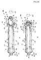
- a blood component separation apparatus 10 has syringes 11, 12, and 13 and two connection devices 14.
- the syringe 11 is used for blood collection.
- the syringe 11 is used for weak centrifugation of blood (whole blood) obtained by blood collection.
- the syringe 12 and one connection device 14 are used for sucking a centrifuged division 55 ( Fig. 9(B) ) separated by weak centrifugation.
- the syringe 12 is used for strong centrifugation of the sucked centrifuged division 55.
- the syringe 13 and the other connection device 14 are used for sucking a supernatant 57 ( Fig. 9(D) ) separated by strong centrifugation.
- the syringes 11 and 12 are equivalent to a first syringe.
- the syringes 12 and 13 are equivalent to a second syringe. Since the syringes 11, 12, and 13 have the same configuration, the syringe 11 is described below.
- the syringe 11 has a syringe barrel 20, a blood collection needle 15, a cap 16, a gasket 35, and a plunger 25.
- the syringe barrel 20 has a cylindrical shape.
- the diameter of one end in a longitudinal direction 105 (direction along the central axis line) of the syringe barrel 20 is reduced, whereby a port 21 to/from which the blood collection needle 15 and the cap 16 are attached and detached is constituted.
- the diameter of the other end of the syringe barrel 20 is not reduced and opens.
- the gasket 35 is inserted from an opening 22 of the syringe barrel 20.
- the gasket 35 has a columnar portion 36 on the side of the opening 22 and a cone portion 37 on the side of the port 21.
- the columnar portion 36 has a columnar shape whose outer diameter is almost the same as the internal diameter of the syringe barrel 20 and is stuck to the inner circumferential surface of the syringe barrel 20 over the entire circumference.
- the gasket 35 seals the internal space of the syringe barrel 20 in a fluid-tight manner.
- the cone portion 37 is formed into a conical shape according to the shape of a bottom surface 23 in such a manner as to be able to be stuck to the bottom surface 23 of the syringe barrel 20.
- the cone portion 37 is stuck to the bottom surface 23 of the syringe barrel 20 when the gasket 35 is deeply pressed into the syringe barrel 20.
- mixing of the air into the collected blood, the sucked centrifuged division 55, and the sucked supernatant 57 ( Fig. 9 ) is suppressed.
- the gasket 35 has a screw hole 38 into which a screw portion 26 of the plunger 25 is screwed.
- the plunger 25 is a rod-shape member and has the screw portion 26, which is screwed into the screw hole 38 of the gasket 35, on one end portion in the axial direction.
- the plunger 25 is inserted into the syringe barrel 20 from the side of the screw portion 26 to be attached to the gasket 35.
- the plunger 25 is attached to the syringes 11, 12, and 13 in blood collection and sucking of the centrifuged division 55 and the supernatant 57 ( Fig. 9 ) and is removed from the syringes 11 and 12 in centrifugal separation.
- a user operates the plunger 25 to cause the gasket 35 to move back and forth along the longitudinal direction 105.
- the cap 16 has a large diameter portion 30, a small diameter portion 31 disposed inside the large diameter portion 30, and a plug portion 32 disposed inside the small diameter portion 31.
- the inner circumferential surface of the small diameter portion 31 is stuck to the outer circumferential surface of the port 21 over the entire circumference.
- the plug portion 32 enters the internal space of the port 21 to block the internal space.
- the cap 16 is attached to the syringe barrel 20 in centrifugal separation and the like.
- Glass, resin materials, and the like can be used for the raw materials of the syringe barrel 20, the gasket 35, the plunger 25, and the cap 16.
- the blood component separation apparatus 10 is treated as a disposal article and is sterilized, it is common to form the syringe barrel 20 and the plunger 25 with a molded article of polypropylene, to form the cap 16 with a molded article of polypropylene or elastomer, and to form the gasket 35 with a molded article of elastomer.
- connection device 14 is attached to the syringes 12 and 13 for use when sucking the centrifuged division 55 and the supernatant 57.
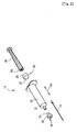
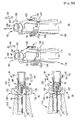
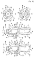
- the connection device 14 has a first member 40, a second member 60, a hollow needle 17, and a hub 42 ( Fig. 5 ).
- the first member 40 is a member which holds the hub 42 and the hollow needle 17.
- the second member 60 is a member which covers a tip 18 of the hollow needle 17.
- the first member 40 is a resin molded article of polypropylene or the like having a cylindrical base 41, reinforcing ribs 44, a first flange 45, a second flange 46, and a support portion 48.
- the following description is given while defining a direction parallel to the central axis line of the base 41 as an axial direction 100, one direction of the axial direction 100 as a first direction 101, the other direction as a second direction 102, and the circumferential direction of the base 41 as a circumferential direction 103.
- the axial direction 100 is equivalent to the longitudinal direction.
- the second member 60 is illustrated to be opposite to the attachment direction to the first member 40 in the axial direction 100 so that the configuration of the second member 60 is clearly illustrated.
- the hub 42 is disposed in the internal space (equivalent to the first internal space) on a side in the second direction 102 of the base 41.
- the hub 42 is a member into the internal space of which the port 21 ( Fig. 2 ) of the syringe barrel 20 is press-fitted.
- the connection device 14 is attached to and detached from the syringes 12 and 13 through the hub 42.
- the diameter of an end portion on a side in the first direction 101 of the base 41 is further reduced than that of the other portions, whereby a small diameter portion 43 is constituted.
- the small diameter portion 43 moves into/out of the internal space of the cylinder portion 61 of the second member 60 in relative movement in the axial direction 100 of the first member 40 and the second member 60 and guides the second member 60 in the axial direction 100.
- the first flange 45 has a disk shape and is projected toward the outside from the outer circumferential surface of an end portion on a side in the second direction 102 of the base 41. For example, a user places a finger on the first flange 45, and then press-fits the port 21 ( Fig. 2 ) of the syringe barrel 20 into the hub 42 ( Fig. 5 ) to attach the connection device 14 to the syringe barrel 20.
- the second flange 46 has a disk shape and is projected toward the outside from the outer circumferential surface of the base 41.
- the second flange 46 is provided on a side in the second direction 102 of the small diameter portion 43.
- a diameter D1 of the second flange 46 illustrated in Fig. 6 is slightly smaller than an internal diameter D2 ( Fig. 3 ) of the syringe barrel 20.
- the second flange 46 guides the connection device 14 in the longitudinal direction 105 of the syringe barrel 20 when the connection device 14 is inserted into the syringe barrel 20.
- the second flange 46 is provided with four insertion holes 47 into which elastic portions 63 of the second member 60 are inserted.
- the four insertion holes 47 are equally disposed at an interval of 90° in the circumferential direction 103.
- the reinforcing ribs 44 are projected toward the outside from the outer circumferential surface of the base 41, and extend along the axial direction 100.
- the four reinforcing ribs 44 are provided on the base 41.
- the four reinforcing ribs 44 are equally disposed at an interval of 90° in the circumferential direction 103.
- the four reinforcing ribs 44 are shifted by only 45° in the circumferential direction 103 with respect to the insertion holes 47 in such a manner as not to interfere with the elastic portions 63 inserted into the insertion holes 47.
- connection device 14 can be inserted into the syringe barrel 20 as illustrated in Fig. 8 .
- the support portion 48 is provided on a side in the second direction 102 of the second flange 46.
- the support portion 48 elastically deforms the elastic portions 63 of the second member 60 in relative movement in the axial direction 100 of the first member 40 and the second member 60.
- the support portion 48 has four inclines 49 in a tapered shape which outwardly spread in the second direction 102.
- the inclines 49 each are provided at a position between the two reinforcing ribs 44 in the circumferential direction 103.
- claws 65 of the elastic portions 63 slide on the inclines 49, and projection pieces 64 of the elastic portions 63 are elastically deformed.
- a concave portion 51 which is dented from the outer circumferential surface of the base 41 is provided on a side in the first direction 101 of the abutting rib 50.
- the concave portion 51 is provided on the entire circumferential surface in the direction 103 ( Fig. 4 ) of the base 41.
- Figs. 7(A) and 7(C) when the second member 60 is pulled by a user in the first direction 101, the claws 65 of the elastic portions 63 move beyond the abutting rib 50 to be fitted into the concave portion 51.
- the second member 60 is fixed to the first member 40 by the fitting of the claws 65 into the concave portion 51.
- the fixation of the second member 60 is performed when a series of operations for obtaining PRP ( Fig. 9 ) are completed, and then the connection device 14 is discarded.
- the concave portion 51 is equivalent to the engagement portion and the lock mechanism.
- the surface on a side in the second direction 102 of the abutting rib 50 is formed into a curved surface in such a manner that the claws 65 can move beyond the abutting rib 50.
- a curved surface may be formed on the claws 65.
- a side in the first direction 101 of the tip of the projection of the abutting rib 50 is edged in such a manner that the claws 65 are not separated from the concave portion 51.
- the hollow needle 17 is disposed at a position overlapping the central axis line of the base 41.
- the hollow needle 17 is connected to the hub 42 at the base end.
- the tip 18 of the hollow needle 17 is projected from the small diameter portion 43 in the first direction 101.
- a projection amount L3 ( Fig. 7(B) ) of the hollow needle 17 from the small diameter portion 43 is slightly larger than a thickness T ( Fig. 3 ) of the gasket 35.
- the hollow needle 17 can penetrate the gasket 35.
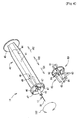
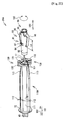
- the second member 60 has a cylinder portion 61, a flange 62, and four elastic portions 63.
- the second member 60 is a resin molded article molded with polypropylene or the like. Therefore, the elastic portions 63 can be elastically deformed.
- the second member 60 is attached to the first member 40 by inserting the elastic portions 63 into the insertion holes 47 from the first direction 101 side. Whirl-stop of the second member 60 in the circumferential direction 103 is performed by abutting of the elastic portions 63 on the wall surface of the insertion holes 47 in the circumferential direction 103.
- the internal diameter D3 of the cylinder portion 61 is slightly larger than an outer diameter D4 of the small diameter portion 43.
- the small diameter portion 43 moves into/out of the cylinder portion 61.
- the second member 60 is guided in the axial direction 100.
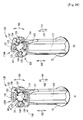
- the second member 60 is caused to move back and forth with respect to the first member 40 between a first position illustrated in Fig. 7(A) and a second position illustrated in Fig. 7(B) .
- the internal space of the cylinder portion 61 is equivalent to the second internal space.
- an outer diameter D5 of the cylinder portion 61 is smaller than a diameter D6 ( Fig. 3 ) of the screw hole 38 of the gasket 35.
- a diameter D6 Fig. 3
- the connection device 14 is inserted into the syringe barrel 20
- the cylinder portion 61 enters the screw hole 38 of the gasket 35.
- a length L2 of the cylinder portion 61 in the axial direction 100 is longer than the projection amount L3 ( Fig. 7(B) ) of the tip 18 of the hollow needle 17 and is almost the same as a length L1 of the small diameter portion 43 in the axial direction 100.
- the cylinder portion 61 accommodates the tip 18 of the hollow needle 17 at the first position illustrated in Fig. 7(A) , and then covers the small diameter portion 43 at the second position illustrated in Fig. 7(B) to expose the tip 18 of the hollow needle 17.
- the length L2 is almost the same as a depth D7 ( Fig. 3 ) of the screw hole 38 of the gasket 35. Therefore, as illustrated in Fig. 8(A) , when the cylinder portion 61 abuts on the bottom surface of the screw hole 38, the flange 62 and the gasket 35 abut on each other.
- the flange 62 has a disk shape and is projected toward the outside in the radial direction of the cylinder portion 61 from the end on a side in the second direction 102 of the outer circumferential surface of the cylinder portion 61. As illustrated in Fig. 7(B) , the flange 62 abuts on the second flange 46 of the first member 40 when the second member 60 reaches the second position. Thus, the movement of the second member 60 beyond the second position is restrained.
- the elastic portions 63 have the four pieces 64 projected from the flange 62 and the claws 65 formed at the tip of the projections of the projection piece 64.
- the projection pieces 64 are disposed at an interval of 90° in the circumferential direction 103.
- the projection pieces 64 are inserted into the insertion holes 47 of the second flange 46 of the first member 40.
- the claws 65 are projected toward the inclines 49 of the support portion 48 from the tip portion of the projections of the projection pieces 64 and abut on the inclines 49 at the first position.
- the claws 65 slide on the inclines 49, so that the projection pieces 64 are elastically deformed.
- the elastically deformed projection pieces 64 elastically energize the cylinder portion 61 in the first direction 101 with respect to the first member 40.
- connection device 14 when the connection device 14 is attached to the syringe 12 and is inserted into the syringe barrel 20 of the syringe 11 is described with reference to Fig. 7 and Fig. 8 .
- connection device 14 is attached to the syringe barrel of the syringe 12 through the hub 42.
- the connection device 14 may be attached to the syringes 12 and 13 beforehand in manufacturing.
- the tip 18 of the hollow needle 17 is covered with the second member 60.
- connection device 14 is inserted into the syringe barrel 20 of the syringe 11 from the second member 60 side by a user.
- the cylinder portion 61 enters the screw hole 38 of the gasket 35 of the syringe 11, and then abuts on the bottom surface of the screw hole 38.
- the connection device 14 is further pressed into the syringe barrel 20
- the second member 60 is pressed by the gasket 35 to be moved relative to the first member 40 in the second direction 102.
- the tip 18 of the hollow needle 17 gradually moves out of the second member 60 to be stuck into the bottom surface of the screw hole 38.
- the tip 18 of the hollow needle 17 penetrates the gasket 35.
- the internal space of the syringe barrel 20 of the syringe 11 and the internal space of the syringe barrel 20 of the syringe 12 are made to communicate with each other through the internal space of the hollow needle 17.
- the relative movement of the second member 60 to the first member 40 is restrained by abutting of the flange 62 on the second flange 46 of the first member 40. Therefore, when the connection device 14 is further pressed into the syringe barrel 20, the gasket 35 is pressed by the connection device 14 to be moved to the bottom surface 23 ( Fig. 3 ) side of the syringe barrel 20.
- the first member 40 When the connection device 14 is inserted into the syringe barrel 20 of the syringe 11, the first member 40 is moved to the second position from the first position, so that the claws 65 of the elastic portions 63 slide on the inclines 49 of the support portion 48 as illustrated in Figs. 7(A) and 7(B) .
- the projection pieces 64 are elastically bent. With the elasticity of the bent projection pieces 64, the second member 60 is elastically energized in the first direction 101 with respect to the first member 40.
- connection device 14 When the connection device 14 is drawn out from the syringe barrel 20 of the syringe 11 by a user, the second member 60 is moved relative to the first member 40 in the first direction 101 with the elasticity of the projection pieces 64 to be returned to the first position illustrated in Fig. 7(A) .
- the claws 65 of the elastic portions 63 abut on the abutting rib 50 of the first member 40 to restrain the movement of the second member 60. Due to the fact that the second member 60 is returned to the first position, the tip 18 of the hollow needle 17 is accommodated in the cylinder portion 61 of the second member 60.
- the second member 60 at the first position illustrated in Fig. 7(A) is pulled by a user in the first direction 101 with respect to the first member 40 to be in the state illustrated in Fig. 7(C) .
- the user places a finger on the flange 62, and then pulls the second member 60 in the first direction 101 with respect to the first member 40, for example.
- the projection pieces 64 are elastically bent, so that the claws 65 of the elastic portions 63 move beyond the abutting rib 50 of the first member 40.
- the claws 65 moving beyond the abutting rib 50 are fitted into the concave portion 51 with the elasticity of the bent projection pieces 64. Due to the fact that the claws 65 are fitted into the concave portion 51, the second member 60 is fixed to the first member 40 in the state where the tip 18 of the hollow needle 17 is accommodated. The connection device 14 is discarded in this state.
- the blood collection needle 15 ( Fig. 2 ) is attached to the syringe barrel 20 of the syringe 11
- the plunger 25 ( Fig. 2 ) is attached to the gasket 35, and then blood collection is performed.
- the blood in the syringe barrel 20 is the whole blood and contains red blood cells, white blood cells, blood platelets, plasma, and the like.
- the plunger 25 is removed from the gasket 35 of the syringe 11, and then the syringe barrel 20 of the syringe 11 is attached to a centrifuge ( Fig. 9(A) ).
- the removal of the plunger 25 from the gasket 35 can reduce a possibility that the gasket 35 is accidentally moved.
- the weak centrifugation is commonly used in centrifugal separation of blood and is generally defined as "Centrifugal separation of separating the whole blood into red blood cells and other components (white blood cells, blood platelets, plasma)" (Non-patent Literature 1). Specifically, the centrifugal separation in the range where the centrifugal separation conditions are about 500 to 2500 rpm is regarded as the weak centrifugation.
- the reason for performing the weak centrifugation lies in suppressing concentration of blood platelets near the boundary of the centrifuged division 55 and the centrifuged division 56 which are separated and increasing the concentration of the blood platelets in the obtained PRP. Since the centrifuge is a commonly used one, the detailed explanation is omitted.
- the syringe barrel 20 is disposed in such a manner that the central axis line is brought into agreement with the radial direction of rotation and the opening 22 side is the rotation center side.
- the blood (whole blood) in the syringe barrel 20 is separated into a centrifuged division 56 in the lower side containing red blood cells and the centrifuged division 55 in the upper side containing white blood cells, blood platelets, and plasma.
- connection device 14 attached to the syringe 12 is inserted into the syringe barrel 20 of the syringe 11 ( Fig. 9(B) ).
- the centrifuged division 55 is sucked by the syringe 12 through the hollow needle 17 of the connection device 14.
- red blood cells are collected in the syringe 11 and white blood cells, blood platelets, and plasma are collected in the syringe 12.
- the red blood cells are discarded or are used for another purpose.
- the connection device 14 is removed from the syringe 12, and then the cap 16 is attached to the syringe barrel 20.
- the plunger 25 is removed from the syringe 12 ( Fig. 9(C) ).
- the syringe barrel 20 of the syringe 12 is attached to a centrifuge. Strong centrifugation is performed by the centrifuge.
- the strong centrifugation is commonly used in centrifugal separation of blood and is generally defined as "Centrifugal separation of separating blood platelets, white blood cells, and remaining red blood cells from plasma” (Non-patent Literature 1).
- the centrifugal separation of concentrating the blood platelets to the bottom portion of the syringe barrel 20 is referred to as the strong centrifugation.
- the centrifugal separation in the range where the centrifugal separation conditions are about 3000 to 4000 rpm is regarded as the strong centrifugation.
- the syringe barrel 20 is disposed in such a manner that the central axis line is brought into agreement with the radial direction of rotation and the opening 22 side is the rotation center side.
- the centrifuged division 55 is separated into PRP in the lower side containing a large number of the blood platelets and the supernatant 57.
- connection device 14 attached to the syringe 13 is inserted into the syringe barrel 20 of the syringe 12 ( Fig. 9(D) ).
- the supernatant 57 is sucked by the syringe 13 through the hollow needle 17 of the connection device 14.
- the PRP is obtained in the syringe 12.
- the concentration of the blood platelets in the PRP is not always defined clearly. However, when the number of the blood platelets per mL is the concentration of the blood platelets, one in which the concentration of the blood platelets is concentrated to 3 to 7 times as high as the concentration of the blood platelets in the extracted whole blood is regarded as the PRP, for example.
- the PRP can also be obtained only by one centrifugal separation.
- the strong centrifugation is performed in the syringe barrel 20 of the syringe 11 to separate the whole blood into a centrifuged division in the lower side containing red blood cells, PRP, and a supernatant.
- the supernatant is sucked by the syringe 12.
- the plunger 25 is attached to the syringe barrel 20 of the syringe 11, and then the centrifuged division in the lower side containing red blood cells is discharged from the syringe barrel 20.
- the PRP is obtained in the syringe 11.
- connection device 14 since the connection device 14 is provided with the hollow needle 17, it is not necessary to pass the hollow needle 17 into the connection device 14. Until when the connection device 14 is inserted into the internal space of the syringe barrel 20 to abut on the gasket 35, the tip 18 of the hollow needle 17 is in the second member 60. After the connection device 14 abuts on the gasket 35 to be pressed into the internal space of the syringe barrel 20, the tip 18 of the hollow needle 17 is in the syringe barrel 20. Therefore, in a series of operations for obtaining the PRP, a user can be prevented from accidentally pricking the user with the hollow needle 17.
- the movement of the second member 60 beyond the first position can be restrained by providing the abutting rib 50.
- the second member 60 can be fixed to the first member 40 when discarding the connection device, and a possibility that the tip 18 of the hollow needle 17 is accidentally exposed in the discarded connection device 14 can be reduced.
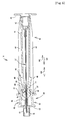
- connection device 24 has a first member 70, a second member 80, a hollow needle 17, and a hub 42.
- the first material 70 is a member which holds the hollow needle 17, and is attached to and detached from syringes 12 and 13.
- the second member 80 is a member which covers a tip 18 of the hollow needle 17.
- the first member 70 is a resin molded article of polypropylene or the like having a base 71, reinforcing ribs 44, a first flange 45, and a third flange 72.
- the base 71 has a cylindrical shape. The following description is given while defining a direction parallel to the central axis line of the base 71 as an axial direction 100, one direction of the axial direction 100 as a first direction 101, the other direction as a second direction 102, and the circumferential direction of the base 71 as a circumferential direction 103.
- the axial direction 100 is equivalent to the longitudinal direction.
- the second member 80 is illustrated in the state where the attachment direction of the second member 80 to the first member 70 is rotated by 90° in the circumferential direction 103 so that the configuration of the second member 80 is clearly illustrated.
- the hub 42 is disposed in the internal space on a side in the second direction 102 of the base 71.
- the connection device 24 is attached to and detached from the syringe 12 and the syringe 13 through the hub 42.
- a small diameter portion 43 is provided in an end portion on a side in the first direction 101 of the base 71.
- a cylinder portion 81 of the second member 80 is disposed in the internal space (equivalent to the first internal space) of the base 71.
- the first member 70 movably supports the second member 80 in the axial direction 100.
- the base 71 has two long holes 73 extending in the first direction 101 from the central portion of the base 71 in the axial direction 100.
- the two long holes 73 are provided penetrating the base 71 in the radial direction at positions facing each other in the radial direction.
- elastic pieces 82 of the second member 80 are projected from the internal space of the base 71 toward the outside of the base 71 through the long holes 73.
- a pair of projections 75 and a pair of convex portions 76 are projected from a pair of wall surfaces 74 which face each other in the circumferential direction 103 ( Fig. 10 ) among the wall surfaces of the long holes 73.
- the pair of projections 75 are provided on an end portion on a side in the first direction 101 of the wall surfaces 74 and face each other in the circumferential direction 103.
- the projections 75 are provided apart from a third flange 72 described later on a side in the second direction 102 of the flange 72.
- claws 83 provided at the tip of the elastic pieces 82 of the second member 80 are press-fitted between the third flange 72 and the projections 75. The claws 83 are caught in the projections 75 and latched by the projections 75.
- a pair of convex portions 76 are provided at almost the central portion of the wall surfaces 74 in the axial direction 100 and face each other in the circumferential direction 103.
- a distance L4 between the tips of projections of the pair of convex portion 76 is made slightly shorter than a width W1 of the elastic pieces 82. Specifically, the distance L4 is made shorter than the width W1 in such a manner that the elastic pieces 82 can pass through between the pair of convex portions 76 by elastic deformation of the elastic pieces 82 and elastic deformation of the convex portions 76.
- the convex portions 76 abut on the elastic pieces 82 to fix the second member 80 before the connection device 24 is discarded as described later.
- the surface on a side in the second direction 102 of the pair of convex portions 76 is formed into a curved surface in such a manner that the elastic pieces 82 can pass. Moreover, sides in the first direction 101 of the tips of projections of the pair of convex portions 76 are edged in such a manner that the second member 80 does not return to the first position.
- the pair of convex portions 76 are equivalent to the engagement portion and the lock mechanism.
- the third flange 72 has the same configuration as that of the second flange 46 except that the insertion holes 47 are not provided.
- Two reinforcing ribs 44 extend in the axial direction 100 from the first flange 45 to the third flange 72.
- the reinforcing ribs 44 are shifted by only 90° in the circumferential direction 103 with respect to the long holes 73 in such a manner as not to overlap with the long holes 73 of the base 71.
- the second member 80 has a cylinder portion 81 and a pair of elastic pieces 82 extending from the cylinder portion 81.
- the second member 80 is a resin molded article molded with polypropylene or the like. Therefore, the elastic pieces 82 of the second member 80 can be elastically deformed.
- the cylinder portion 81 has a cylindrical shape in which an outer diameter D11 is smaller than an internal diameter D8 of the base 71.
- the cylinder portion 81 is inserted into the base 71 from an opening on a side in the first direction 101 of the base 71.
- the second member 80 is guided in the axial direction 100 in the cylinder portion 81.
- the second member 80 is moved back and forth in the axial direction 100 relative to the first member 70 between a first position illustrated in Fig. 13(A) and a second position illustrated in Fig. 13(B) .
- the internal space of the cylinder portion 81 is equivalent to the second internal space.
- a distance L5 between top portions 84 of the pair of chevron-shaped elastic pieces 82 in the radial direction of the base 71 is made longer than the internal diameter D2 ( Fig. 3 ) of the syringe barrel 20.
- the elastic pieces 82 abut on the edge of an opening 22 of the syringe barrel 20.
- an outer diameter D9 of the hollow needle 17 is made smaller than an internal diameter D10 of the cylinder portion 81.
- the hollow needle 17 is disposed in the cylinder portion 81 and the base 71 and is connected to the hub 42 ( Fig. 11 ) at the base end.
- the tip of the hollow needle 17 is projected in the first direction 101 by only a projection amount L3 ( Fig. 7 ) from the small diameter portion 43 of the first member 70.
- the hollow needle 17 can penetrate a gasket 35 ( Fig. 14(B) ).
- connection device 24 [Operation of connection device 24]
- connection device 24 is attached to the syringe 12 and inserted into the syringe barrel 20 of the syringe 11 is described with reference to Fig. 13 and Fig. 14 .
- connection device 24 is attached to the syringe barrel 20 of the syringe 12 through the hub 42. A user holds the first member 90 in the hand to attach the connection device 34 to the syringe 12.
- the connection device 24 may be attached to the syringe 12 in manufacturing.
- the second member 80 When the connection device 24 is not inserted into the syringe barrel 20 of the syringe 11, the second member 80 is positioned at the first position illustrated in Fig. 13(A) .
- the second member 80 at the first position accommodates the tip 18 of the hollow needle 17.
- the elastic pieces 82 are elastically deformed at the tip latched by the first member 70 as the base point to be elastically deformed from the chevron shape illustrated in Fig. 14(A) to a gentle chevron shape close to a linear shape illustrated in Fig. 14(B) .
- the elastically deformed elastic pieces 82 elastically energize the cylinder portion 81 in the first direction 101 with respect to the first member 70.
- the cylinder portion 81 is moved from the first position to the second position by being pressed in the second direction 102 by the gasket 35 or by the elastic deformation of the elastic pieces 82.
- the tip 18 of the hollow needle 17 is exposed.
- the tip 18 of the exposed hollow needle 17 is stuck into the bottom surface of the screw hole 38 of the gasket 35, and penetrates the gasket 35.
- the elastic pieces 82 are positioned inside the inner circumferential surface of the syringe barrel 20 at the second position where the hollow needle 17 penetrates the gasket 35, and are not further elastically deformed. Moreover, at the second position, a cylinder 81 is positioned inside the small diameter portion 43, and is not further pressed by the gasket 35. Therefore, the second member 80 is not moved beyond the second position.
- the second member 80 When the connection device 24 is removed from the syringe barrel 20, the second member 80 is moved to the first position illustrated in Fig. 13(A) from the second position illustrated in Fig. 13(B) with the elasticity of the elastic pieces 82, and covers the tip 18 of the hollow needle 17. When the second member 80 is moved to the first position, the elastic pieces 82 abut on the pair of convex portions 76. Thus, the movement of the second member 80 beyond the first position is restrained.
- connection device 24 when the connection device 24 is discarded is described with reference to Fig. 13 .
- the second member 80 at the first position illustrated in Fig. 13(A) is moved in the first direction 101 with respect to the first member 70 by a user.
- the user moves the second member 80 with respect to the first member 70 by holding the cylinder portion 81, and then pulling the same in the first direction 101 or pressing the elastic pieces 82 in the first direction 101, for example.
- the elastic pieces 82 pass through between the pair of convex portions 76 by the elastic deformation of the elastic pieces 82 or the elastic deformation of the convex portions 76. Due to the fact that the elastic pieces 82 pass through between the pair of convex portions 76, the second member 80 is fixed to the first member 70 ( Fig. 13(C) ).
- the connection device 24 is discarded in this state.
- the hollow needle 17 is formed in the connection device 24, it is not necessary to pass the hollow needle 17 into the connection device 24. Moreover, when the connection device 24 is not inserted into the internal space of the syringe barrel 20, the tip 18 of the hollow needle 17 is in the second member 80 and when the connection device 24 is inserted into the syringe barrel 20, the tip 18 of the hollow needle 17 is in the syringe barrel 20. Therefore, in a series of operations for obtaining PRP, a user can be prevented from accidentally pricking the user with the hollow needle 17.
- This modification describes the example in which the elastic pieces 82 are provided in such a manner as to abut on the edge of the opening 22 of the syringe barrel 20 when the tip of the cylinder portion 81 abuts on the bottom surface of the screw hole 38 of the gasket 35.
- the elastic pieces 82 may be provided in such a manner as to abut on the edge of the opening 22 of the syringe barrel 20 before the cylinder portion 81 abuts on the bottom surface of the screw hole 38.
- connection device 34 illustrated in Fig. 15 .
- those having the same configurations as those of the connection device 14 and the connection device 24 are denoted by the same reference numerals.
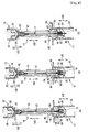
- the connection device 34 has a first member 90, a second member 110, a hollow needle 17, and a hub 42.
- the first member 90 is a member which holds the hollow needle 17 and the hub 42.
- the second member 110 is a member which covers a tip 18 of the hollow needle 17.
- the first member 90 is a resin molded article of polypropylene or the like having a cylinder portion 92 having a cylindrical shape and elastic portions 93 extended from the cylinder portion 92. Therefore, the elastic portions 93 can be elastically deformed.
- the following description is given while defining a direction parallel to the central axis line of the cylinder portion 92 as an axial direction 100, one direction of the axial direction 100 as a first direction 101, the other direction as a second direction 102, and the circumferential direction of the cylinder portion 92 as a circumferential direction 103.
- the axial direction 100 is equivalent to the longitudinal direction.
- the hub 42 is inserted into the internal space (equivalent to the first internal space) of the cylinder portion 92 from an opening on a side in the second direction 102 of the cylinder portion 92 and is attached to the first member 90.
- the first member 90 is moved relative to the second member 110 in the axial direction 100 in the internal space (equivalent to the second internal space) of a base 111 of the second member 110 as described later.
- the cylinder portion 92 has a pair of through-holes 94.
- the pair of through-holes 94 penetrate the cylinder portion 92 at positions facing each other in the radial direction of the cylinder portion 92.
- the through-holes 94 are formed at almost the central portion in the axial direction 100 of the cylinder portion 92.
- the elastic portion 93 has a flange 95, a projection piece 96, and a pair of bosses 97.
- the flange 95 is projected in the radial direction from the end on a side in the second direction 102 of the outer circumferential surface of the cylinder portion 92.
- the flange 95 abuts on the base 111 of the second member 110, and restrains relative movement in the axial direction 100 of the first member 90 and the second member 110.
- the projection pieces 96 are projected in the first direction 101 from the flange 95.
- the projection pieces 96 slide on inclines 113 of the second member 110 to be elastically bent.
- the bent projection pieces 96 elastically energize the second member 110 in the first direction 101 with respect to the first member 90.
- the pair of bosses 97 are projected in the circumferential direction 103 from both side surfaces in the circumferential direction 103 at the tips of the projection pieces 96. As illustrated in Fig. 18(A) , the bosses 97 abut on elastic pieces 121 of the second member 110, and restrains relative movement in the axial direction 100 of the first member 90 and the second member 110.
- the first member 90 is restrained from moving relative to the second member 110 by the abutting of the bosses 97 on the elastic pieces 121 and the abutting of the flange 95 on the base 111. Therefore, the moving range of the first member 90 to the second member 110 in the axial direction 100 is within the range of a length L8 ( Fig. 15 ) of the projection pieces 96 in the axial direction 100.
- the length L8 of the projection pieces 96 is made longer than a thickness T ( Fig. 3 ) of a gasket 35 in such a manner that the tip 18 of the hollow needle 17 can penetrate the gasket 35 ( Fig. 3 ).
- the hollow needle 17 is connected to the hub 42 at the base end and is projected in the first direction 101 from the first member 90.
- the second member 110 is a resin molded article of polypropylene or the like having a base 111, four reinforcing ribs 112, a third flange 72, and lock mechanisms 120.
- the base 111 has a cylindrical shape extending in the axial direction 100. As illustrated in Fig. 17 , an internal diameter D12 of the base 111 is made slightly larger than an outer diameter D13 of the cylinder portion 92 of the first member 90. The cylinder portion 92 is inserted into the base 111 from an opening on a side in the second direction 102 of the base 111. The base 111 is guided in the axial direction 100 by the cylinder portion 92. The second member 110 is moved back and forth relative to the first member 90 in the axial direction 100 between a first position illustrated in Fig. 18(A) and a second position illustrated in Fig. 18(B) .
- a small diameter portion 43 is provided on an end portion on a side in the first direction 101 of the base 111.
- the base 111 is set to a length according to the length of the hollow needle 17 in the axial direction 100 in such a manner that the small diameter portion 43 covers the tip 18 of the hollow needle 17 at the first position.
- the reinforcing ribs 112 are projected in the radial direction from the outer circumferential surface of the base 111 and extend in the axial direction 100.
- the four reinforcing ribs 112 are disposed at an interval of 90° in the circumferential direction 103.
- the tip surfaces of projections of the reinforcing ribs 112 on a side in the second direction 102 constitute inclines 113 approaching the outer circumferential surface of the base 111 toward the second direction 102.
- the projection pieces 96 of the first member 90 slide on the inclines 113.
- a pair of lock mechanisms 120 are provided on the end on a side in the second direction 102 of the base 111 facing each other in the radial direction of the base 111.
- the lock mechanism 120 has the elastic pieces 121, a holding portion 122 provided to the elastic pieces 121, and an engagement convex portion 123 projected from the holding portion 122.
- the elastic piece 121 is constituted in an approximately U shape, which is elastically deformed, and one end thereof is joined to the base 111 and the other end is joined to the holding portion 122.
- the elastic piece 121 elastically energizes the holding portion 122 to the outside in the radial direction of the base 111.
- the elastic piece 121 is equivalent to the energizing portion.
- a pair of the elastic pieces 121 are provided on both sides of the holding portion 122 in the circumferential direction of the second member 110.
- the holding portion 122 is elastically supported by both the pair of elastic pieces 121.
- the elastic pieces 121 of one lock mechanism 120 and the elastic pieces 121 of the other lock mechanism 120 are separated only by a distance L6 ( Fig. 19(A) ) in the radial direction of the base 111.
- the distance L6 is made longer than a width W2 ( Fig. 15 ) of the projection pieces 96 of the first member 90.
- the projection pieces 96 are extended to the inclines 113 through between the pair of elastic pieces 121, and abut on the inclines 113 at the tip.
- the distance L6 is made shorter than a distance L7 ( Fig. 15 ) between the tips of projections of the pair of bosses 97 of the first member 90.
- the bosses 97 abut on the elastic pieces 121, so that the relative movement of the first member 90 and the second member 110 is restrained.
- the holding portion 122 is provided in the middle of the pair of elastic pieces 121.
- the holding portion 122 has a plate shape along the outer circumferential surface of the base 111.
- the holding portion 122 supports the engagement convex portion 123 facing the through-hole 94 of the first member 90 in the state where the second member 110 is attached to the first member 90.
- the pair of holding portions 122 of the pair of lock mechanisms 120 face each other in the radial direction of the base 111.
- the engagement convex portions 123 are projected from the holding portions 122 toward the central portion of the base 111.
- a pair of notches 114 which are notched from the end surface on a side in the second direction 102 are provided in the base 111, and the tips of the engagement convex portions 123 are located in the notches 114.
- the notches 114 are located between end portions of the sides joined to the base 111 of the pair of elastic pieces 121 which constitute the lock mechanisms 120. More specifically, the edge of the notch 114 serves as an end portion of the side joined to the base 111 of the elastic piece 121.
- a pair of projections 124 in a triangular shape as viewed in plane are projected in the circumferential direction 103 from both the side surfaces of the engagement convex portions 123 in the circumferential direction 103.
- the projections 124 are projected from the engagement convex portion 123 to each of the pair of elastic pieces 121.
- connection device 34 is attached to the syringe 12 and inserted into the syringe barrel 20 of the syringe 11 is described with reference to Fig. 18 and Fig. 21 .
- connection device 34 may be attached to the syringe 12.
- the tip 18 of the hollow needle 17 is covered with the second member 110.
- connection device 34 attached to the syringe 12 is inserted into the syringe barrel 20 of the syringe 11 from the side of the small diameter portion 43.
- the small diameter portion 43 abuts on the bottom surface of the screw hole 38 of the gasket 35 of the syringe 11.
- the second member 110 is moved relative to the first member 90 in the axial direction 100 as illustrated in Fig. 21(B) .
- the tip 18 of the hollow needle 17 is projected from the small diameter portion 43 to be stuck into the gasket 35.
- the second member 110 reaches the second position, so that the hollow needle 17 penetrates the gasket 35.
- the projection pieces 96 slide on the inclines 113 to be elastically bent.
- the bent projection pieces 96 elastically energize the second member 110 in the second direction 102 with respect to the first member 90.
- connection device 34 When the connection device 34 is removed from the syringe barrel 20 of the syringe 11, the second member 110 is moved in the second direction 102 with respect to the first member 90 with the elasticity of the bent projection pieces 96 to be returned to the first position.
- the tip 18 of the hollow needle 17 is covered with the small diameter portion 43.
- Fig. 20 After a series of operations for obtaining PRP ( Fig. 9 ) are completed, the pair of holding portions 122 are held by a user. Thus, the lock mechanisms 120 are moved to a position illustrated in Fig. 20(B) and 20(D) from a position illustrated in Fig. 20(A) and 20(C) by the elastic deformation of the elastic pieces 121. Thus, the engagement convex portions 123 of the lock mechanisms 120 are fitted into the through-holes 94 of the first member 90, and the projections 124 are caught in the edges of the notches 114 ( Fig. 19(A) ).
- the pair of projections 124 and end potions of the sides joined to the base 111 of the pair of elastic pieces 121 are engaged with each other.
- the first member 90 is fixed to the second member 110 in the state where the second member 110 accommodates the tip 18 of the hollow needle 17.
- the connection device 34 is discarded in this state.
- the hollow needle 17 is provided in the connection device 34, it is not necessary to pass the hollow needle 17 into the connection device 34. Moreover, the tip 18 of the hollow needle 17 is in the second member 60 and abuts on the gasket 35 until the connection device 34 is inserted into the internal space of the syringe barrel 20 and abuts on the gasket 35 and the tip 18 of the hollow needle 17 is in the syringe barrel 20 after the connection device 34 abuts on the gasket 35, and is further pressed into the internal space of the syringe barrel 20. Therefore, in a series of operations for obtaining PRP, a user can be prevented from accidentally pricking the user with the hollow needle 17.
- connection device 34A illustrated in Fig. 22 .
- those having the same configurations of the connection devices 14, 24, and 34 are denoted by the same reference numerals.
- connection device 34A according to Modification 3 the configuration of a lock mechanism 130 described later is different from that in the connection device 34 according to Modification 2 and the other configurations are the same as those of the connection device 34 according to Modification 2. Therefore, the following description is given with reference to some of the drawings of Modification 2.
- the connection device 34A has a first member 90, a second member 110A, a hollow needle 17, and a hub 42.
- the first member 90 is a member which holds the hollow needle 17 and the hub 42.
- the second member 110A is a member which covers a tip 18 of the hollow needle 17.
- the first member 90 illustrated in Fig. 22 is constituted by a cylinder portion 92 and elastic portions 93 as in Modification 2 and the hub 42 is attached to an opening on a side in the second direction 102 of the cylinder portion 92.
- the first member 90 is moved relative to the second member 110A in the axial direction 100 in the internal space (equivalent to the second internal space) of the base 111 of the second member 110A as described later.
- Through-holes 94 provided at almost the center of the cylinder portion 92 in the axial direction 100, engagement convex portions 133 of the second member 110A are fitted when the connection device 34A is discarded as in Modification 2.
- the through-holes 94 are equivalent to the engagement concave portions.
- the elastic portion 93 illustrated in Fig. 22 has a flange 95, a projection pieces 96, and a pair of bosses 97 as in Modification 2. As illustrated in Fig. 23(B) , the flange 95 abuts on the base 111 of the second member 110A, and restrains relative movement in the axial direction 100 of the first member 90 and the second member 110A.
- the projection pieces 96 slide on inclines 113 of the second member 110A to be elastically bent in the relative movement of the first member 90 and the second member 110A.
- the bent projection pieces 96 elastically energize the second member 110A in the first direction 101 with respect to the first member 90.
- the bosses 97 abut on the elastic pieces 131 of the second member 110A, and restrain relative movement in the axial direction 100 of the first member 90 and the second member 110A.
- the first member 90 is restrained from the relative movement to the second member 110A by the abutting of the bosses 97 and the elastic pieces 131 on the abutting of the flange 95 on the base 111. Therefore, the moving range to the second member 110A of the first member 90 in the axial direction 100 is within the range of a length L8 ( Fig. 22 ) of the projection pieces 96 in the axial direction 100.
- the length L8 of the projection pieces 96 is made longer than a thickness T ( Fig. 3 ) of a gasket 35 in such a manner that the tip 18 of the hollow needle 17 can penetrate the gasket 35 ( Fig. 3 ).
- the second member 110A is a resin molded article of polypropylene or the like having a base 111, four reinforcing ribs 112, a third flange 72, and lock mechanisms 130.
- the configurations of the base 111, the four reinforcing ribs 112, and the third flange 72 are the same as those of Modification 2.
- a pair of lock mechanisms 130 are provided on the end on a side in the second direction 102 of the base 111 facing each other in the radial direction of the base 111.
- the lock mechanism 130 has the elastic pieces 131, a holding portion 132 provided to the elastic pieces 131, and an engagement convex portion 133 projected from the holding portion 132.
- a pair of the elastic piece 131 are provided on both sides of the holding portion 132 in the circumferential direction 103 of the second member 110A.
- One of the pair of elastic pieces 131 is formed into an almost U shape, which is elastically deformed, and one end thereof is joined to the base 111 and the other end is joined to the holding portion 132. More specifically, the elastic pieces 131 elastically energize the holding portion 132 to the outside in the radial direction of the base 111.
- the elastic pieces 131 are equivalent to the energizing portion.
- the other one of the pair of elastic pieces 131 is joined only to the base 111 and is separated from the holding portion 132. More specifically, the holding portion 132 is elastically supported by only one of the pair of elastic pieces 131.
- the elastic pieces 131 of one lock mechanism 130 and the elastic pieces 131 of the other lock mechanism 130 are separated from each other only by a distance L6 ( Fig. 24(A) ) in the radial direction of the base 111.
- the distance L6 is made longer than a width W2 ( Fig. 15 ) of the projection pieces 96 of the first member 90.
- the projection pieces 96 are extended to inclines 113 through between the pair of elastic pieces 131, and abut on the inclines 113 at the tip.
- the distance L6 is made shorter than a distance L7 ( Fig. 15 ) between the tips of projections of the pair of bosses 97 of the first member 90.
- the bosses 97 abut on the elastic pieces 131, so that the relative movement of the first member 90 and the second member 110A is restrained.
- the holding portion 132 is provided in the middle of the pair of elastic pieces 131.
- the holding portion 132 has a plate shape along the outer circumferential surface of the base 111.
- the holding portion 132 supports the engagement convex portion 133 facing the through-hole 94 of the first member 90 in the state where the second member 110A was attached to the first member 90.
- the pair of holding portions 132 of the pair of lock mechanisms 130 face each other in the radial direction of the base 111.
- the engagement convex portions 133 are projected from the holding portions 132 toward the central portion of the base 111.
- a pair of notches 114 which are notched from the end surface on a side in the second direction 102 are provided in the base 111, and the tips of the engagement convex portions 133 are located in this notches 114.
- the edge of the notch 114 in Modification 3 serves as an end portion of the other one of the pair of elastic pieces 131 (i.e., the elastic piece 131 which does not support the holding portion 132).
- the tips of the engagement convex portions 133 are projected to the inside of the inner circumferential surface of the base 111 ( Fig. 24(B) ), and are fitted into the through-holes 94 of the first member 90 at the first position ( Figs. 25(B), 25(D) ).
- projections 134 in a triangular shape as viewed in plane are projected in the circumferential direction 103 from one side surface of the engagement convex portions 133 in the circumferential direction 103.
- the projections 134 are projected from the engagement convex portions 133 toward the other one of the pair of elastic pieces 131 (i.e., the elastic piece 131 which does not support the holding portion 132).
- the projections 134 are caught in the edges of the notches 114 of the base 111 (i.e., engaged with the other elastic piece 131), and are latched by the base 111.
- the first member 90 is fixed to the second member 110A.
- the projections 134 are equivalent to the lock portion.
- connection device 34A An operation when discarding the connection device 34A is described with reference to Fig. 25 .
- the pair of holding portions 132 are held by a user.
- the lock mechanisms 130 are moved to a position illustrated in Fig. 25(B) and 25(D) from a position illustrated in Fig. 25(A) and 25(C) by the elastic deformation of the elastic pieces 131.
- the engagement convex portions 133 of the lock mechanisms 130 are fitted into the through-holes 94 of the first member 90, and the projections 134 are caught in the edges of the notches 114 ( Fig. 24(B) ).
- the projections 134 and the other elastic pieces 131 are engaged with each other.
- the first member 90 is fixed to the second member 110A in the state where the second member 110A accommodates the tip 18 of the hollow needle 17.
- the connection device 34A is discarded in this state.
- the hollow needle 17 is provided in the connection device 34A, it is not necessary to pass the hollow needle 17 into the connection device 34A. Moreover, the tip 18 of the hollow needle 17 is in the second member 60 and abuts on the gasket 35 until the connection device 34A is inserted into the internal space of the syringe barrel 20 and abuts on the gasket 35. The tip 18 of the hollow needle 17 is in the syringe barrel 20 after the connection device 34A abuts on the gasket 35, and is further pressed into the internal space of the syringe barrel 20. Therefore, in a series of operations for obtaining PRP, a user can be prevented from accidentally pricking the user with the hollow needle 17.
- the embodiment and the modifications described above describe the examples in which the cylinder portion 61 and the elastic portions 63, the cylinder portion 81 and the elastic pieces 82, and the cylinder portion 92 and the elastic portions 93 are integrally molded with resin materials.
- a plate spring may be provided in place of the elastic portions 63, the elastic pieces 82, or the elastic portions 93.
- the plate spring is formed into the same shape as that of the elastic portions 63, the elastic pieces 82, or the elastic portions 93, and is stuck to the cylinder portion 61, the cylinder portion 81, or the cylinder portion 92.
- a connection portion attached to and detached from the port 21 of the syringe barrel 20 may be directly formed in the first members 40, 70, and 90 by molding in place of the hub 42.
- a hub having a screw hole into which the port 21 is screwed may be used in place of the hub 42 into which the port 21 is press-fitted.
Landscapes
- Health & Medical Sciences (AREA)
- Heart & Thoracic Surgery (AREA)
- Engineering & Computer Science (AREA)
- Life Sciences & Earth Sciences (AREA)
- General Health & Medical Sciences (AREA)
- Biomedical Technology (AREA)
- Veterinary Medicine (AREA)
- Hematology (AREA)
- Public Health (AREA)
- Animal Behavior & Ethology (AREA)
- Anesthesiology (AREA)
- Vascular Medicine (AREA)
- Pulmonology (AREA)
- Environmental & Geological Engineering (AREA)
- External Artificial Organs (AREA)
- Measurement Of The Respiration, Hearing Ability, Form, And Blood Characteristics Of Living Organisms (AREA)
- Medical Preparation Storing Or Oral Administration Devices (AREA)
- Centrifugal Separators (AREA)
- Infusion, Injection, And Reservoir Apparatuses (AREA)
Applications Claiming Priority (2)
| Application Number | Priority Date | Filing Date | Title |
|---|---|---|---|
| JP2012068208 | 2012-03-23 | ||
| PCT/JP2013/051861 WO2013140858A1 (ja) | 2012-03-23 | 2013-01-29 | 接続装置及び血液成分分離装置 |
Publications (3)
| Publication Number | Publication Date |
|---|---|
| EP2829288A1 true EP2829288A1 (de) | 2015-01-28 |
| EP2829288A4 EP2829288A4 (de) | 2015-12-09 |
| EP2829288B1 EP2829288B1 (de) | 2018-08-15 |
Family
ID=49222325
Family Applications (1)
| Application Number | Title | Priority Date | Filing Date |
|---|---|---|---|
| EP13765200.4A Active EP2829288B1 (de) | 2012-03-23 | 2013-01-29 | Verbindungsvorrichtung und vorrichtung zur trennung von blutkomponenten |
Country Status (5)
| Country | Link |
|---|---|
| US (1) | US9968769B2 (de) |
| EP (1) | EP2829288B1 (de) |
| JP (1) | JP6123792B2 (de) |
| SG (1) | SG11201405981UA (de) |
| WO (1) | WO2013140858A1 (de) |
Cited By (1)
| Publication number | Priority date | Publication date | Assignee | Title |
|---|---|---|---|---|
| ES2593042A1 (es) * | 2015-06-03 | 2016-12-05 | Biotechnology Institute, I Mas D, S.L. | Dispositivo de recolección de sangre o de un compuesto sanguíneo |
Families Citing this family (17)
| Publication number | Priority date | Publication date | Assignee | Title |
|---|---|---|---|---|
| US20150209502A1 (en) | 2014-01-27 | 2015-07-30 | Arthrex, Inc. | Triple syringe and methods of making platelet-enriched plasma and use thereof |
| USD903859S1 (en) * | 2014-05-07 | 2020-12-01 | Maureen Brown | Insemination syringe |
| US11350967B2 (en) | 2014-05-07 | 2022-06-07 | Mosie Llc | Apparatus including a cylindrical body and a nub |
| USD827817S1 (en) | 2015-03-02 | 2018-09-04 | Neomed, Inc. | Enteral syringe |
| USD831204S1 (en) | 2015-03-02 | 2018-10-16 | Neomed, Inc. | Enteral syringe |
| USD825747S1 (en) * | 2015-03-02 | 2018-08-14 | Neomed, Inc. | Enteral syringe |
| USD807502S1 (en) * | 2015-03-02 | 2018-01-09 | Neomed, Inc. | Enteral syringe |
| USD831203S1 (en) | 2015-03-02 | 2018-10-16 | Neomed, Inc. | Enteral syringe |
| US10624817B2 (en) | 2015-03-24 | 2020-04-21 | Neomed, Inc. | Oral administration coupler for back-of-mouth delivery |
| US10682287B2 (en) | 2015-07-14 | 2020-06-16 | Neomed, Inc. | Dosing control coupling for enteral fluid transfer and enteral couplings and syringes |
| AU2016294538B2 (en) | 2015-07-14 | 2020-04-02 | Neomed, Inc. | Dosing control coupling for enteral fluid transfer |
| JP1594716S (de) * | 2017-03-07 | 2018-01-15 | ||
| EP3799896B1 (de) | 2019-10-04 | 2025-09-10 | Arthrex, Inc | Vorrichtungen und verfahren zur herstellung therapeutischer flüssigkeiten |
| USD937421S1 (en) * | 2020-04-02 | 2021-11-30 | Wise S.R.L. | Foldable medical electrode |
| TWI780828B (zh) * | 2020-07-23 | 2022-10-11 | 仁寶電腦工業股份有限公司 | 穿刺裝置及採血裝置 |
| EP4429738A4 (de) * | 2021-11-11 | 2025-06-25 | PRP Technologies, Inc. | Probensammelvorrichtung |
| JPWO2024043028A1 (de) * | 2022-08-25 | 2024-02-29 |
Family Cites Families (12)
| Publication number | Priority date | Publication date | Assignee | Title |
|---|---|---|---|---|
| US4762516A (en) | 1987-03-05 | 1988-08-09 | Luther Medical Products, Inc. | Assembly of needle catheter protector |
| US4832696A (en) * | 1987-03-05 | 1989-05-23 | Luther Medical Products, Inc. | Assembly of needle and protector |
| US6171284B1 (en) * | 2000-03-15 | 2001-01-09 | Wang-Hsiang Kao | Syringe needle cover structure |
| AU2002950988A0 (en) * | 2002-08-26 | 2002-09-12 | Afra Design Pty Ltd | Single use retractable needle |
| JP4364696B2 (ja) | 2004-03-30 | 2009-11-18 | ニプロ株式会社 | 組織または器官再生用材料 |
| JP2006232834A (ja) | 2005-02-23 | 2006-09-07 | Allan Mishra | 組織損傷の治療のための方法及びキット |
| US9050403B2 (en) | 2006-10-27 | 2015-06-09 | Nipro Corporation | Platelet-rich plasma separator and platelet-rich plasma separation method |
| JP4983204B2 (ja) * | 2006-10-27 | 2012-07-25 | ニプロ株式会社 | 遠心分離容器及び遠心分離方法 |
| WO2009046560A2 (de) * | 2007-10-12 | 2009-04-16 | Otto Hess | Sicherheitsanordnung für die kanüle eines invasiven instruments |
| WO2009148969A1 (en) | 2008-06-02 | 2009-12-10 | Sta-Med, Llc | Needle cover assembly for a syringe |
| GB201001506D0 (en) * | 2010-02-01 | 2010-03-17 | Liversidge Barry P | Medical needle safety device |
| AU2011273725B2 (en) * | 2010-07-02 | 2015-11-05 | Sanofi-Aventis Deutschland Gmbh | Safety device for a pre-filled syringe and injection device |
-
2013
- 2013-01-29 EP EP13765200.4A patent/EP2829288B1/de active Active
- 2013-01-29 US US14/386,461 patent/US9968769B2/en active Active
- 2013-01-29 JP JP2014506064A patent/JP6123792B2/ja active Active
- 2013-01-29 WO PCT/JP2013/051861 patent/WO2013140858A1/ja not_active Ceased
- 2013-01-29 SG SG11201405981UA patent/SG11201405981UA/en unknown
Cited By (4)
| Publication number | Priority date | Publication date | Assignee | Title |
|---|---|---|---|---|
| ES2593042A1 (es) * | 2015-06-03 | 2016-12-05 | Biotechnology Institute, I Mas D, S.L. | Dispositivo de recolección de sangre o de un compuesto sanguíneo |
| WO2016193513A1 (es) * | 2015-06-03 | 2016-12-08 | Biotechnology Institute, I Mas D, S.L., | Dispositivo de recolección de sangre |
| US10376194B2 (en) | 2015-06-03 | 2019-08-13 | Biotechnology Institute, I Mas D, S.L. | Device for the collecting of blood or a blood compound |
| TWI700108B (zh) * | 2015-06-03 | 2020-08-01 | 西班牙商生物技術研究公司 | 用於收集血液或血液複合物的裝置 |
Also Published As
| Publication number | Publication date |
|---|---|
| SG11201405981UA (en) | 2014-10-30 |
| JP6123792B2 (ja) | 2017-05-10 |
| JPWO2013140858A1 (ja) | 2015-08-03 |
| EP2829288A4 (de) | 2015-12-09 |
| US9968769B2 (en) | 2018-05-15 |
| EP2829288B1 (de) | 2018-08-15 |
| WO2013140858A1 (ja) | 2013-09-26 |
| US20150073356A1 (en) | 2015-03-12 |
Similar Documents
| Publication | Publication Date | Title |
|---|---|---|
| US9968769B2 (en) | Connection device and blood component separation apparatus | |
| US9050403B2 (en) | Platelet-rich plasma separator and platelet-rich plasma separation method | |
| CN1268287C (zh) | 带有卫生针尖保护的刺血针 | |
| CN1185025C (zh) | 针头装置 | |
| US11426531B2 (en) | Medical injector cap remover | |
| US20180177949A1 (en) | Backstop for a Syringe | |
| JPH0337408B2 (de) | ||
| US10912507B2 (en) | Skin pricking device | |
| US10105084B2 (en) | Blood sampler | |
| EP3437681A1 (de) | Vorrichtung zur verabreichung von medikamenten verfahren zur verabreichung von medikamenten und verfahren zur herstellung einer vorrichtung zur verabreichung von medikamenten | |
| KR101575165B1 (ko) | 안전캡이 포함되는 시술용 침. | |
| CN110614169A (zh) | 一种富血小板血浆制备的专用离心管组件及其应用方法 | |
| KR200486998Y1 (ko) | 특정성분 추출이 가능한 의료용 주사기 키트 | |
| JP2019514470A (ja) | ニードル貯蔵マガジンアセンブリ | |
| JP3770738B2 (ja) | シールド付注射器 | |
| US20250017501A1 (en) | Collector Accessory for Small Volume Collection Containers and Related Sample Collection Methods | |
| JPH1028739A (ja) | 医療用穿刺具 | |
| JP2002263188A (ja) | 導液具 |
Legal Events
| Date | Code | Title | Description |
|---|---|---|---|
| PUAI | Public reference made under article 153(3) epc to a published international application that has entered the european phase |
Free format text: ORIGINAL CODE: 0009012 |
|
| 17P | Request for examination filed |
Effective date: 20141020 |
|
| AK | Designated contracting states |
Kind code of ref document: A1 Designated state(s): AL AT BE BG CH CY CZ DE DK EE ES FI FR GB GR HR HU IE IS IT LI LT LU LV MC MK MT NL NO PL PT RO RS SE SI SK SM TR |
|
| AX | Request for extension of the european patent |
Extension state: BA ME |
|
| DAX | Request for extension of the european patent (deleted) | ||
| RA4 | Supplementary search report drawn up and despatched (corrected) |
Effective date: 20151111 |
|
| RIC1 | Information provided on ipc code assigned before grant |
Ipc: A61M 5/32 20060101ALI20151105BHEP Ipc: A61M 1/02 20060101AFI20151105BHEP Ipc: A61M 5/315 20060101ALI20151105BHEP Ipc: A61M 1/00 20060101ALI20151105BHEP Ipc: A61M 5/31 20060101ALI20151105BHEP Ipc: A61M 5/178 20060101ALI20151105BHEP |
|
| STAA | Information on the status of an ep patent application or granted ep patent |
Free format text: STATUS: EXAMINATION IS IN PROGRESS |
|
| 17Q | First examination report despatched |
Effective date: 20170421 |
|
| GRAP | Despatch of communication of intention to grant a patent |
Free format text: ORIGINAL CODE: EPIDOSNIGR1 |
|
| STAA | Information on the status of an ep patent application or granted ep patent |
Free format text: STATUS: GRANT OF PATENT IS INTENDED |
|
| INTG | Intention to grant announced |
Effective date: 20180412 |
|
| GRAS | Grant fee paid |
Free format text: ORIGINAL CODE: EPIDOSNIGR3 |
|
| GRAA | (expected) grant |
Free format text: ORIGINAL CODE: 0009210 |
|
| STAA | Information on the status of an ep patent application or granted ep patent |
Free format text: STATUS: THE PATENT HAS BEEN GRANTED |
|
| AK | Designated contracting states |
Kind code of ref document: B1 Designated state(s): AL AT BE BG CH CY CZ DE DK EE ES FI FR GB GR HR HU IE IS IT LI LT LU LV MC MK MT NL NO PL PT RO RS SE SI SK SM TR |
|
| REG | Reference to a national code |
Ref country code: CH Ref legal event code: EP Ref country code: GB Ref legal event code: FG4D Ref country code: AT Ref legal event code: REF Ref document number: 1029014 Country of ref document: AT Kind code of ref document: T Effective date: 20180815 |
|
| REG | Reference to a national code |
Ref country code: IE Ref legal event code: FG4D |
|
| REG | Reference to a national code |
Ref country code: DE Ref legal event code: R096 Ref document number: 602013042054 Country of ref document: DE |
|
| REG | Reference to a national code |
Ref country code: NL Ref legal event code: MP Effective date: 20180815 |
|
| REG | Reference to a national code |
Ref country code: LT Ref legal event code: MG4D |
|
| REG | Reference to a national code |
Ref country code: AT Ref legal event code: MK05 Ref document number: 1029014 Country of ref document: AT Kind code of ref document: T Effective date: 20180815 |
|
| PG25 | Lapsed in a contracting state [announced via postgrant information from national office to epo] |
Ref country code: BG Free format text: LAPSE BECAUSE OF FAILURE TO SUBMIT A TRANSLATION OF THE DESCRIPTION OR TO PAY THE FEE WITHIN THE PRESCRIBED TIME-LIMIT Effective date: 20181115 Ref country code: AT Free format text: LAPSE BECAUSE OF FAILURE TO SUBMIT A TRANSLATION OF THE DESCRIPTION OR TO PAY THE FEE WITHIN THE PRESCRIBED TIME-LIMIT Effective date: 20180815 Ref country code: RS Free format text: LAPSE BECAUSE OF FAILURE TO SUBMIT A TRANSLATION OF THE DESCRIPTION OR TO PAY THE FEE WITHIN THE PRESCRIBED TIME-LIMIT Effective date: 20180815 Ref country code: GR Free format text: LAPSE BECAUSE OF FAILURE TO SUBMIT A TRANSLATION OF THE DESCRIPTION OR TO PAY THE FEE WITHIN THE PRESCRIBED TIME-LIMIT Effective date: 20181116 Ref country code: NO Free format text: LAPSE BECAUSE OF FAILURE TO SUBMIT A TRANSLATION OF THE DESCRIPTION OR TO PAY THE FEE WITHIN THE PRESCRIBED TIME-LIMIT Effective date: 20181115 Ref country code: IS Free format text: LAPSE BECAUSE OF FAILURE TO SUBMIT A TRANSLATION OF THE DESCRIPTION OR TO PAY THE FEE WITHIN THE PRESCRIBED TIME-LIMIT Effective date: 20181215 Ref country code: LT Free format text: LAPSE BECAUSE OF FAILURE TO SUBMIT A TRANSLATION OF THE DESCRIPTION OR TO PAY THE FEE WITHIN THE PRESCRIBED TIME-LIMIT Effective date: 20180815 Ref country code: FI Free format text: LAPSE BECAUSE OF FAILURE TO SUBMIT A TRANSLATION OF THE DESCRIPTION OR TO PAY THE FEE WITHIN THE PRESCRIBED TIME-LIMIT Effective date: 20180815 Ref country code: NL Free format text: LAPSE BECAUSE OF FAILURE TO SUBMIT A TRANSLATION OF THE DESCRIPTION OR TO PAY THE FEE WITHIN THE PRESCRIBED TIME-LIMIT Effective date: 20180815 Ref country code: SE Free format text: LAPSE BECAUSE OF FAILURE TO SUBMIT A TRANSLATION OF THE DESCRIPTION OR TO PAY THE FEE WITHIN THE PRESCRIBED TIME-LIMIT Effective date: 20180815 |
|
| PG25 | Lapsed in a contracting state [announced via postgrant information from national office to epo] |
Ref country code: AL Free format text: LAPSE BECAUSE OF FAILURE TO SUBMIT A TRANSLATION OF THE DESCRIPTION OR TO PAY THE FEE WITHIN THE PRESCRIBED TIME-LIMIT Effective date: 20180815 Ref country code: LV Free format text: LAPSE BECAUSE OF FAILURE TO SUBMIT A TRANSLATION OF THE DESCRIPTION OR TO PAY THE FEE WITHIN THE PRESCRIBED TIME-LIMIT Effective date: 20180815 Ref country code: HR Free format text: LAPSE BECAUSE OF FAILURE TO SUBMIT A TRANSLATION OF THE DESCRIPTION OR TO PAY THE FEE WITHIN THE PRESCRIBED TIME-LIMIT Effective date: 20180815 |
|
| PG25 | Lapsed in a contracting state [announced via postgrant information from national office to epo] |
Ref country code: PL Free format text: LAPSE BECAUSE OF FAILURE TO SUBMIT A TRANSLATION OF THE DESCRIPTION OR TO PAY THE FEE WITHIN THE PRESCRIBED TIME-LIMIT Effective date: 20180815 Ref country code: EE Free format text: LAPSE BECAUSE OF FAILURE TO SUBMIT A TRANSLATION OF THE DESCRIPTION OR TO PAY THE FEE WITHIN THE PRESCRIBED TIME-LIMIT Effective date: 20180815 Ref country code: CZ Free format text: LAPSE BECAUSE OF FAILURE TO SUBMIT A TRANSLATION OF THE DESCRIPTION OR TO PAY THE FEE WITHIN THE PRESCRIBED TIME-LIMIT Effective date: 20180815 Ref country code: ES Free format text: LAPSE BECAUSE OF FAILURE TO SUBMIT A TRANSLATION OF THE DESCRIPTION OR TO PAY THE FEE WITHIN THE PRESCRIBED TIME-LIMIT Effective date: 20180815 Ref country code: IT Free format text: LAPSE BECAUSE OF FAILURE TO SUBMIT A TRANSLATION OF THE DESCRIPTION OR TO PAY THE FEE WITHIN THE PRESCRIBED TIME-LIMIT Effective date: 20180815 Ref country code: RO Free format text: LAPSE BECAUSE OF FAILURE TO SUBMIT A TRANSLATION OF THE DESCRIPTION OR TO PAY THE FEE WITHIN THE PRESCRIBED TIME-LIMIT Effective date: 20180815 |
|
| REG | Reference to a national code |
Ref country code: DE Ref legal event code: R097 Ref document number: 602013042054 Country of ref document: DE |
|
| PG25 | Lapsed in a contracting state [announced via postgrant information from national office to epo] |
Ref country code: SK Free format text: LAPSE BECAUSE OF FAILURE TO SUBMIT A TRANSLATION OF THE DESCRIPTION OR TO PAY THE FEE WITHIN THE PRESCRIBED TIME-LIMIT Effective date: 20180815 Ref country code: DK Free format text: LAPSE BECAUSE OF FAILURE TO SUBMIT A TRANSLATION OF THE DESCRIPTION OR TO PAY THE FEE WITHIN THE PRESCRIBED TIME-LIMIT Effective date: 20180815 Ref country code: SM Free format text: LAPSE BECAUSE OF FAILURE TO SUBMIT A TRANSLATION OF THE DESCRIPTION OR TO PAY THE FEE WITHIN THE PRESCRIBED TIME-LIMIT Effective date: 20180815 |
|
| PLBE | No opposition filed within time limit |
Free format text: ORIGINAL CODE: 0009261 |
|
| STAA | Information on the status of an ep patent application or granted ep patent |
Free format text: STATUS: NO OPPOSITION FILED WITHIN TIME LIMIT |
|
| 26N | No opposition filed |
Effective date: 20190516 |
|
| PG25 | Lapsed in a contracting state [announced via postgrant information from national office to epo] |
Ref country code: SI Free format text: LAPSE BECAUSE OF FAILURE TO SUBMIT A TRANSLATION OF THE DESCRIPTION OR TO PAY THE FEE WITHIN THE PRESCRIBED TIME-LIMIT Effective date: 20180815 Ref country code: MC Free format text: LAPSE BECAUSE OF FAILURE TO SUBMIT A TRANSLATION OF THE DESCRIPTION OR TO PAY THE FEE WITHIN THE PRESCRIBED TIME-LIMIT Effective date: 20180815 |
|
| REG | Reference to a national code |
Ref country code: CH Ref legal event code: PL |
|
| PG25 | Lapsed in a contracting state [announced via postgrant information from national office to epo] |
Ref country code: LU Free format text: LAPSE BECAUSE OF NON-PAYMENT OF DUE FEES Effective date: 20190129 |
|
| REG | Reference to a national code |
Ref country code: BE Ref legal event code: MM Effective date: 20190131 |
|
| REG | Reference to a national code |
Ref country code: IE Ref legal event code: MM4A |
|
| PG25 | Lapsed in a contracting state [announced via postgrant information from national office to epo] |
Ref country code: BE Free format text: LAPSE BECAUSE OF NON-PAYMENT OF DUE FEES Effective date: 20190131 |
|
| PG25 | Lapsed in a contracting state [announced via postgrant information from national office to epo] |
Ref country code: CH Free format text: LAPSE BECAUSE OF NON-PAYMENT OF DUE FEES Effective date: 20190131 Ref country code: LI Free format text: LAPSE BECAUSE OF NON-PAYMENT OF DUE FEES Effective date: 20190131 |
|
| PG25 | Lapsed in a contracting state [announced via postgrant information from national office to epo] |
Ref country code: IE Free format text: LAPSE BECAUSE OF NON-PAYMENT OF DUE FEES Effective date: 20190129 |
|
| PG25 | Lapsed in a contracting state [announced via postgrant information from national office to epo] |
Ref country code: TR Free format text: LAPSE BECAUSE OF FAILURE TO SUBMIT A TRANSLATION OF THE DESCRIPTION OR TO PAY THE FEE WITHIN THE PRESCRIBED TIME-LIMIT Effective date: 20180815 |
|
| PG25 | Lapsed in a contracting state [announced via postgrant information from national office to epo] |
Ref country code: MT Free format text: LAPSE BECAUSE OF NON-PAYMENT OF DUE FEES Effective date: 20190129 Ref country code: PT Free format text: LAPSE BECAUSE OF FAILURE TO SUBMIT A TRANSLATION OF THE DESCRIPTION OR TO PAY THE FEE WITHIN THE PRESCRIBED TIME-LIMIT Effective date: 20181215 |
|
| PG25 | Lapsed in a contracting state [announced via postgrant information from national office to epo] |
Ref country code: CY Free format text: LAPSE BECAUSE OF FAILURE TO SUBMIT A TRANSLATION OF THE DESCRIPTION OR TO PAY THE FEE WITHIN THE PRESCRIBED TIME-LIMIT Effective date: 20180815 |
|
| PG25 | Lapsed in a contracting state [announced via postgrant information from national office to epo] |
Ref country code: HU Free format text: LAPSE BECAUSE OF FAILURE TO SUBMIT A TRANSLATION OF THE DESCRIPTION OR TO PAY THE FEE WITHIN THE PRESCRIBED TIME-LIMIT; INVALID AB INITIO Effective date: 20130129 |
|
| PG25 | Lapsed in a contracting state [announced via postgrant information from national office to epo] |
Ref country code: MK Free format text: LAPSE BECAUSE OF FAILURE TO SUBMIT A TRANSLATION OF THE DESCRIPTION OR TO PAY THE FEE WITHIN THE PRESCRIBED TIME-LIMIT Effective date: 20180815 |
|
| PGFP | Annual fee paid to national office [announced via postgrant information from national office to epo] |
Ref country code: DE Payment date: 20250121 Year of fee payment: 13 |
|
| PGFP | Annual fee paid to national office [announced via postgrant information from national office to epo] |
Ref country code: FR Payment date: 20250127 Year of fee payment: 13 |
|
| PGFP | Annual fee paid to national office [announced via postgrant information from national office to epo] |
Ref country code: GB Payment date: 20250128 Year of fee payment: 13 |