EP2829151B1 - Einstellbare montageklammer und system damit - Google Patents
Einstellbare montageklammer und system damit Download PDFInfo
- Publication number
- EP2829151B1 EP2829151B1 EP13769458.4A EP13769458A EP2829151B1 EP 2829151 B1 EP2829151 B1 EP 2829151B1 EP 13769458 A EP13769458 A EP 13769458A EP 2829151 B1 EP2829151 B1 EP 2829151B1
- Authority
- EP
- European Patent Office
- Prior art keywords
- clip
- gripping
- middle portion
- adjustable mounting
- tripod
- Prior art date
- Legal status (The legal status is an assumption and is not a legal conclusion. Google has not performed a legal analysis and makes no representation as to the accuracy of the status listed.)
- Active
Links
Images


Classifications
-
- G—PHYSICS
- G03—PHOTOGRAPHY; CINEMATOGRAPHY; ANALOGOUS TECHNIQUES USING WAVES OTHER THAN OPTICAL WAVES; ELECTROGRAPHY; HOLOGRAPHY
- G03B—APPARATUS OR ARRANGEMENTS FOR TAKING PHOTOGRAPHS OR FOR PROJECTING OR VIEWING THEM; APPARATUS OR ARRANGEMENTS EMPLOYING ANALOGOUS TECHNIQUES USING WAVES OTHER THAN OPTICAL WAVES; ACCESSORIES THEREFOR
- G03B17/00—Details of cameras or camera bodies; Accessories therefor
- G03B17/56—Accessories
- G03B17/566—Accessory clips, holders, shoes to attach accessories to camera
-
- H—ELECTRICITY
- H04—ELECTRIC COMMUNICATION TECHNIQUE
- H04M—TELEPHONIC COMMUNICATION
- H04M1/00—Substation equipment, e.g. for use by subscribers
- H04M1/02—Constructional features of telephone sets
- H04M1/04—Supports for telephone transmitters or receivers
-
- A—HUMAN NECESSITIES
- A45—HAND OR TRAVELLING ARTICLES
- A45F—TRAVELLING OR CAMP EQUIPMENT: SACKS OR PACKS CARRIED ON THE BODY
- A45F5/00—Holders or carriers for hand articles; Holders or carriers for use while travelling or camping
-
- F—MECHANICAL ENGINEERING; LIGHTING; HEATING; WEAPONS; BLASTING
- F16—ENGINEERING ELEMENTS AND UNITS; GENERAL MEASURES FOR PRODUCING AND MAINTAINING EFFECTIVE FUNCTIONING OF MACHINES OR INSTALLATIONS; THERMAL INSULATION IN GENERAL
- F16B—DEVICES FOR FASTENING OR SECURING CONSTRUCTIONAL ELEMENTS OR MACHINE PARTS TOGETHER, e.g. NAILS, BOLTS, CIRCLIPS, CLAMPS, CLIPS OR WEDGES; JOINTS OR JOINTING
- F16B2/00—Friction-grip releasable fastenings
- F16B2/02—Clamps, i.e. with gripping action effected by positive means other than the inherent resistance to deformation of the material of the fastening
- F16B2/06—Clamps, i.e. with gripping action effected by positive means other than the inherent resistance to deformation of the material of the fastening external, i.e. with contracting action
- F16B2/12—Clamps, i.e. with gripping action effected by positive means other than the inherent resistance to deformation of the material of the fastening external, i.e. with contracting action using sliding jaws
-
- F—MECHANICAL ENGINEERING; LIGHTING; HEATING; WEAPONS; BLASTING
- F16—ENGINEERING ELEMENTS AND UNITS; GENERAL MEASURES FOR PRODUCING AND MAINTAINING EFFECTIVE FUNCTIONING OF MACHINES OR INSTALLATIONS; THERMAL INSULATION IN GENERAL
- F16M—FRAMES, CASINGS OR BEDS OF ENGINES, MACHINES OR APPARATUS, NOT SPECIFIC TO ENGINES, MACHINES OR APPARATUS PROVIDED FOR ELSEWHERE; STANDS; SUPPORTS
- F16M11/00—Stands or trestles as supports for apparatus or articles placed thereon ; Stands for scientific apparatus such as gravitational force meters
- F16M11/02—Heads
- F16M11/04—Means for attachment of apparatus; Means allowing adjustment of the apparatus relatively to the stand
- F16M11/041—Allowing quick release of the apparatus
-
- F—MECHANICAL ENGINEERING; LIGHTING; HEATING; WEAPONS; BLASTING
- F16—ENGINEERING ELEMENTS AND UNITS; GENERAL MEASURES FOR PRODUCING AND MAINTAINING EFFECTIVE FUNCTIONING OF MACHINES OR INSTALLATIONS; THERMAL INSULATION IN GENERAL
- F16M—FRAMES, CASINGS OR BEDS OF ENGINES, MACHINES OR APPARATUS, NOT SPECIFIC TO ENGINES, MACHINES OR APPARATUS PROVIDED FOR ELSEWHERE; STANDS; SUPPORTS
- F16M13/00—Other supports for positioning apparatus or articles; Means for steadying hand-held apparatus or articles
- F16M13/02—Other supports for positioning apparatus or articles; Means for steadying hand-held apparatus or articles for supporting on, or attaching to, an object, e.g. tree, gate, window-frame, cycle
- F16M13/022—Other supports for positioning apparatus or articles; Means for steadying hand-held apparatus or articles for supporting on, or attaching to, an object, e.g. tree, gate, window-frame, cycle repositionable
-
- H—ELECTRICITY
- H04—ELECTRIC COMMUNICATION TECHNIQUE
- H04M—TELEPHONIC COMMUNICATION
- H04M1/00—Substation equipment, e.g. for use by subscribers
- H04M1/02—Constructional features of telephone sets
-
- H—ELECTRICITY
- H04—ELECTRIC COMMUNICATION TECHNIQUE
- H04M—TELEPHONIC COMMUNICATION
- H04M1/00—Substation equipment, e.g. for use by subscribers
- H04M1/02—Constructional features of telephone sets
- H04M1/11—Supports for sets, e.g. incorporating armrests
- H04M1/12—Adjustable supports, e.g. extensible
-
- A—HUMAN NECESSITIES
- A45—HAND OR TRAVELLING ARTICLES
- A45F—TRAVELLING OR CAMP EQUIPMENT: SACKS OR PACKS CARRIED ON THE BODY
- A45F5/00—Holders or carriers for hand articles; Holders or carriers for use while travelling or camping
- A45F5/1516—Holders or carriers for portable handheld communication devices, e.g. pagers or smart phones
Definitions
- the present invention relates to an adjustable mount, and a system using a flexible support apparatus, such as a tripod, adapted to support an item mounted in the adjustable mount.
- US 2006/0215836 describes an electronic device holder that comprises a body and a clamping assembly, wherein the body is disposed between two sides of the clamping assembly. At least one clamp is slidably connected to either side of the clamping assembly and is provided externally of the body, and a base is provided at bottom of the body and is adapted to support an electronic device.
- a portable electronic device may be enhanced with the use of a tripod or other support structure.
- An adjustable clip adapted to work with varying types of support structures may enhance its versatility.
- an adjustable mount which may adjust to support a variety of different types and sizes of modern devices, such as smart phones.
- an adjustable mount or clamp which allows the mounting of the device to a support structure such as a tripod.
- the present invention is directed towards an adjustable mounting clip for an electronic device, such as a cellular telephone or smart phone.
- the mounting clip may be adapted to be supported by a flexible support apparatus, such as a tripod.
- the mounting clip may support a variety of electronic device types with an automatically adjusting variable clip receiver.
- the adjustable mounting clip of the invention comprises a middle portion, and wherein the extension of said middle portion increases the distance between said first gripping clip and said second gripping clip.
- the mounting clip also comprises a first gripping clip, said first gripping clip comprising one or more device mounting surfaces.
- Said first gripping clip is pivotally attached to a first end of said middle portion along a first pivot axis and is adapted to pivot from a stowed position wherein said one or more device mounting surfaces are parallel to said middle portion to a deployed position, wherein said one or more device mounting surfaces are perpendicular to said middle portion.
- a second gripping clip of the adjustable mounting clip comprises one or more device mounting surfaces and is pivotally attached to a second end of said middle portion along a second pivot axis. Said second gripping clip is adapted to pivot from a stowed position wherein said one or more device mounting surfaces are parallel to said middle portion to a deployed position wherein said one or more device mounting surfaces are perpendicular to said middle portion.
- the adjustable mounting clip is adapted to hold a planar device along a first mounting plane parallel to said middle portion, wherein said first pivot axis and said second pivot axis are parallel to said first mounting plane.
- Said middle portion comprises at least one guide which includes a spring that is configured to apply a contracting force between said first gripping clip and said second gripping clip, said middle portion being extendable along said at least one guide. Said extension of said middle portion is resisted with a spring within said middle portion.
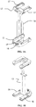
- FIGS 1A-E illustrate an adjustable mounting clip 10 according to some embodiments of the present invention.
- the adjustable mounting clip is adapted to support an electronic device such as a smart phone.
- the electronic device may also be a GPS device, a remote monitor, or other device.
- an adjustable mounting clip 10 has a first gripping clip 11 and a second gripping clip 12.
- the adjustable mounting clip 10 is adapted to attach to a support structure such as a tripod, or a flexible tripod, in some embodiments.
- a central portion 13 adapted to extendably join the first gripping clip 11 and the second gripping clip 12.
- the central portion may allow for extension between the first gripping clip 11 and the second gripping clip 12 along guides 14, 15, which may include a spring loaded retraction aspect adapted to keep pressure on a device held by the adjustable mounting clip.
- the first gripping clip 11 and the second gripping clip 12 may also be spring loaded such that they fold inward into a stowed configuration when not supporting an electronic device.
- the first gripping clip 11 may have resilient portions 16 adapted to provide friction against the device held by the adjustable mounting clip 10.
- the second gripping clip 12 may have resilient portions 17 adapted to provide friction against the device held by the adjustable mounting clip 10.
- the resilient portions 16, 17 may reside in inset portions of the gripping clips 11, 12 in some embodiments.
- the gripping clips 11, 12 may be made of plastic.
- the resilient portions 16, 17 may be co-molded to the gripping clips 11, 12.
- the first gripping clip 11 may have a threaded insert 18 adapted to receive a threaded post, such as may be found on a tripod, or on a removable clip adapted to be inserted into a clip receiver, as may be found on a tripod.
- the first gripping clip 11 may have a lanyard hole 19 which may be used to attach a lanyard which can be used to attach the adjustable mounting clip to another item.
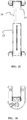
- FIG. 2 illustrates an adjustable mounting clip 10 in various states as it would be taken from a stowed configuration to a deployed configuration.
- the adjustable mounting clip 10 may be adapted to take a very small amount of space, lending well to storage in small spaces, such as the pocket of a user.
- the gripping clips may be in a U-shape, such that the gripping clips, when folded into a stowed configuration, reside outside of the central portion 13.
- the gripping clips 11, 12 may reside in plane with the central portion 13 when stowed, such that the stowed configuration is extremely compact.
- the adjustable mounting clip 10 is spring loaded such that the gripping clips 11, 12 are brought together under spring force.
- the gripping clips 11, 12 may be extended from each other by the user, in order to be of a proper size for a held device. Once the user is no longer pulling the two ends away from each other, the spring loaded aspect of the adjustable mounting clip will then close down on the device being held. The combination of the spring loaded aspect of the clip, and the resilient portions of the gripping clips, allow for a very sure grip of the held device.
- an adjustable mounting clip gives the distinct advantage of allowing the user to hold and position an electronic device, such as a smart phone, in a convenient position for viewing.
- the adjustable mounting clip may be mounted to a tripod which may be placed upon a table, or an airplane seat's foldout tray, for viewing and use.
- the expandable aspect of the central portion 13 allows for use with a variety of sizes of electronic devices.
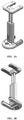
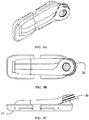
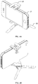
- FIGS 3A and 3B illustrate an adjustable mounting clip 10 in perspective views according to some embodiments of the present invention.
- the adjustable mounting clip 10 is adapted to receive and hold an electronic device, or other device.
- a central portion 13 adapted to extendably join the first gripping clip 11 and the second gripping clip 12.
- the central portion may allow for extension between the first gripping clip 11 and the second gripping clip 12 along guides 14, 15, which may include a spring loaded retraction aspect adapted to keep pressure on a device held by the adjustable mounting clip.
- One or more of the guides 14, 15 may include a spring system adapted to apply a contracting force between the first gripping clip 11 and the second gripping clip 12.
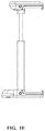
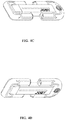
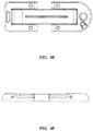
- FIGS 4A-F illustrate an adjustable mounting clip in a stowed configuration according to some embodiments of the present invention.
- the way in which the parts integrate into a stowed whole allows for storage in a small space.
- the gripping clips 11, 12 may be adapted to pivot from a stowed position parallel to the central portion 13 to a deployed position perpendicular to the central portion 13.
- the gripping clips 11, 12 may be U-shaped such that in the stowed position the clips reside outside of the central portion, allowing for a very compact co-planar stowed position.
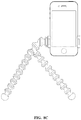
- FIGS 5A-C illustrate an adjustable mounting clip 10 attached to a small folded tripod 30, such as a miniature ball tripod, according to some embodiments of the present invention.
- the tripod may have a plurality of legs which may fold together in order to form a small stowed unit of clip and tripod.
- the adjustable mounting clip is adapted to receive an electronic device.
- the combination of the adjustable mounting clip 10 and the small folded tripod 30 present a very compact system adapted to hold a device.
- the tripod 30 has three legs which rotate around a center ball such that the three legs are parallel when in a stowed position.
- the tripod may have a threaded post which mates into the threaded insert 18 of the adjustable mounting clip. With the adjustable mounting clip in a stowed configuration, the tripod and the clip may align such that the long axis of the stowed clip is parallel to the long axis stowed tripod.
- the tripod legs are adapted to rotate from a first position, which is a closed, or stowed, configuration and seen in Figures 5A-C , to an open, or deployed, position as seen in Figures 6A-B .
- the tripod legs may have tips which may be of a material adapted to provide more friction while in use.
- the stowed position of the tripod places the legs directly adjacent such that they are stowed together into a unitary stowed leg assembly.
- the rings of the ends of the legs may be adapted such that when in a deployed position the rings have stops which prevent further rotation of the legs past a point which places the legs in a tripod configuration.
- a central body ring provides an external surface adapted to provide a support and guide surface to the ends of the legs, which may be rings adapted to fit around the central body ring.
- Within the central body ring there may be a socket adapted to receive a ball connector.
- the ball connector may be spherical in its contact area with the socket.
- a threaded post may protrude from the ball connector and be adapted to support a device such as a camera, or to mate to an adjustable mounting clip, or other device.
- the rings of the legs may have sufficient friction with the central body ring such that the legs may be rotated into either a stowed or a deployed configuration, but will stay in the position under typical usage loads.
- the ball connector may have sufficient friction with the socked of the interior of the central body ring such that once placed in a selected position the ball tends not to move during typical use.
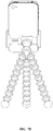
- FIGS 6A-B illustrate an adjustable mounting clip 10 holding an electronic device 31 mounted onto a miniature ball tripod 30.
- the ball tripod 30 is in a deployed configuration wherein the legs have been rotated into a position adapted to support the system.
- An apparatus such as this affords the user the convenience of using a tripod as a support stand for watching video on a personal player, for example, and the use of the adjustable mounting clip allows the user to custom tailor their system for the player being viewed.
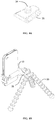
- FIGS 7A-B illustrate an adjustable mounting clip 10 with a clip 32 mounted onto a flexible tripod 33 according to some embodiments of the present invention.
- the clip 32 may be adapted to attach to the adjustable mounting clip 10 along the central portion 13.
- the flexible tripod may have a body portion, which provides a base of support for three flexible legs.
- the flexible legs may consist of a series of interconnected ball and socket joint connectors.
- the flexible legs are able to be flexed into a variety of positions and can be used to support the body portion by forming tripod support.
- the flexible legs are able to adapt to uneven surfaces to allow the tripod to function in a variety of situations.
- the body portion itself may have a series of interconnected ball and socket joint connectors within it, allowing for even more flexibility with regard to its mounting function.
- the flexible legs are illustrated as functioning legs, the legs are of sufficient flexibility that the may be used to wrap around items such as bars or other objects in order to fasten the tripod apparatus to objects that would not be suitable for mounting of a typical tripod. In conjunction with the gripping portion, this allows the tripod apparatus to be fastened to a variety of objects. For example, when used to position a digital camera, the legs may wrap around a vertical gate rail, allowing the mounting of the camera for a photo taking opportunity not previously available.
- the body portion is connected to an interconnect portion adapted to receive a clip 35, illustrated in Figure 8A .
- a clip 35 may be removably fastened to the interconnect portion.
- the clip 35 may have a threaded post 34 adapted to fit into a camera or other device in some embodiments.
- the flexible legs may use connectors that have a co-molded gripping portion.
- the gripping portions may allow for use of the tripod in a variety of ways, including wrapping of the legs around a post or other object.
- the flexible legs may be terminated with a gripping pod. The gripping pod may be fully molded into the cavity of the connector.
- FIGS 8B-C illustrate further uses of an adjustable mounting clip with a tripod mounting clip attached thereto, clipped in the clip receiver of a tripod with flexible legs.
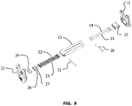
- Figure 9 is an illustrative exploded view of an adjustable mounting clip 10 according to embodiments of the present invention.
- the first gripping clip 11 is pivotally attached to an end of the central portion 13 by a pin 21.
- the second gripping clip 12 is pivotally attached to a slider end 22 by a pin 22.
- the guides 14, 15 are adapted to slide within the central portion 13 while attached at a first end to slider end 22.
- Springs 23 surround the guides 14, 15 and are adapted to retract the adjustable mounting clip 10 such that is places moderate pressure on a support device while supporting it, or to pull the clip into the stowed configuration when no device is held within it.
- End attachments 24, 26, 27 are used to restrain a second end of the springs such that they restrain extension of the second end 12 from the first end 11.
Landscapes
- Engineering & Computer Science (AREA)
- General Engineering & Computer Science (AREA)
- Mechanical Engineering (AREA)
- Signal Processing (AREA)
- Physics & Mathematics (AREA)
- General Physics & Mathematics (AREA)
- Studio Devices (AREA)
- Accessories Of Cameras (AREA)
- Telephone Set Structure (AREA)
Claims (5)
- Einstellbare Befestigungsklammer (10) für eine elektronische Vorrichtung (31), wobei die einstellbare Befestigungsklammer Folgendes umfasst:einen mittleren Abschnitt (13); undeine erste Greifklammer (11), wobei die erste Greifklammer (11) eine oder mehrere Vorrichtungsbefestigungsflächen umfasst, durch die die erste Greifklammer (11) an einem ersten Ende des mittleren Abschnitts (13) entlang einer ersten Schwenkachse schwenkbar angebracht ist; undeine zweite Greifklammer (12), wobei die zweite Greifklammer (12) eine oder mehrere Vorrichtungsbefestigungsflächen umfasst, durch die die zweite Greifklammer (12) an einem zweiten Ende des mittleren Abschnitts (13) entlang einer zweiten Schwenkachse schwenkbar angebracht ist;wobei der mittlere Abschnitt (13) mindestens eine Führung (14, 15) umfasst, die eine Feder umfasst,wobei der mittlere Abschnitt (13) entlang der mindestens einen Führung (14, 15) ausziehbar ist;wobei durch das Ausziehen des mittleren Abschnitts (13) der Abstand zwischen der ersten Greifklammer (11) und der zweiten Greifklammer (12) erhöht wird; und wobei die einstellbare Befestigungsklammer (10) dazu ausgeführt ist, eine planare Vorrichtung (31) entlang einer ersten Befestigungsebene, die parallel zur Erstreckung des mittleren Abschnitts (13) verläuft, zu halten,wobei die erste Greifklammer (11) dazu ausgeführt ist, aus einer Verstauungsposition, in der eine oder mehrere Vorrichtungsbefestigungsflächen zur Erstreckung des mittleren Abschnitts (13) parallel sind, in eine Einsatzposition, in der eine oder mehrere Vorrichtungsbefestigungsflächen zur Erstreckung des mittleren Abschnitts (13) senkrecht sind, zu schwenken; undwobei die zweite Greifklammer (12) dazu ausgeführt ist, aus einer Verstauungsposition, in der eine oder mehrere Vorrichtungsbefestigungsflächen zur Erstreckung des mittleren Abschnitts (13) parallel sind, in eine Einsatzposition, in der eine oder mehrere Vorrichtungsbefestigungsflächen zur Erstreckung des mittleren Abschnitts (13) senkrecht sind, zu schwenken,dadurch gekennzeichnet, dass die Feder dazu konfiguriert ist, eine Zusammenziehkraft zwischen der ersten Greifklammer (11) und der zweiten Greifklammer (12) anzulegen, wobei dem Ausziehen des mittleren Abschnitts (13) mit der Feder in dem mittleren Abschnitt (13) entgegengewirkt wird.
- Einstellbare Befestigungsklammer (10) nach Anspruch 1, wobei die erste Greifklammer (11) einen elastischen Abschnitt (17) entlang einer Vorrichtungsbefestigungsfläche der ersten Greifklammer (11) umfasst.
- Einstellbare Befestigungsklammer (10) nach Anspruch 2, wobei die zweite Greifklammer (12) einen elastischen Abschnitt (17) entlang einer Vorrichtungsbefestigungsfläche der zweiten Greifklammer (12) umfasst.
- Einstellbare Befestigungsklammer (10) nach Anspruch 1, wobei die erste Greifklammer (11) U-förmig ist und wobei die zweite Greifklammer (12) U-förmig ist, so dass sich sowohl die erste Greifklammer (11) als auch die zweite Greifklammer (12) in der Verstauungsposition außerhalb des mittigen Abschnitts befinden.
- System aus einem Dreifuß (30) und einer einstellbaren Klammer (10), das Folgendes umfasst:einen Dreifuß (30);gekennzeichnet durch eine einstellbare Befestigungsklammer (10) nach einem der Ansprüche 1-4.
Applications Claiming Priority (3)
| Application Number | Priority Date | Filing Date | Title |
|---|---|---|---|
| US201261615273P | 2012-03-24 | 2012-03-24 | |
| US13/665,934 US9103487B2 (en) | 2012-03-24 | 2012-11-01 | Adjustable mounting clip and system using same |
| PCT/US2013/033616 WO2013148531A2 (en) | 2012-03-24 | 2013-03-22 | Adjustable mounting clip and system using same |
Publications (3)
| Publication Number | Publication Date |
|---|---|
| EP2829151A2 EP2829151A2 (de) | 2015-01-28 |
| EP2829151A4 EP2829151A4 (de) | 2016-03-16 |
| EP2829151B1 true EP2829151B1 (de) | 2018-09-05 |
Family
ID=49261387
Family Applications (1)
| Application Number | Title | Priority Date | Filing Date |
|---|---|---|---|
| EP13769458.4A Active EP2829151B1 (de) | 2012-03-24 | 2013-03-22 | Einstellbare montageklammer und system damit |
Country Status (4)
| Country | Link |
|---|---|
| US (3) | US9103487B2 (de) |
| EP (1) | EP2829151B1 (de) |
| CN (1) | CN104412700B (de) |
| WO (1) | WO2013148531A2 (de) |
Families Citing this family (129)
| Publication number | Priority date | Publication date | Assignee | Title |
|---|---|---|---|---|
| US9103487B2 (en) * | 2012-03-24 | 2015-08-11 | Daymen Us, Inc. | Adjustable mounting clip and system using same |
| GB201205807D0 (en) * | 2012-03-30 | 2012-05-16 | Tomtom Int Bv | Mobile device docking station |
| US20130233986A1 (en) * | 2012-05-07 | 2013-09-12 | iStabilizer, LLC | Apparatus for supporting mobile phones, electronic tablets and cameras |
| FR2995091B1 (fr) * | 2012-08-28 | 2015-08-14 | Commissariat Energie Atomique | Dispositif d'imagerie a grand angle de vue |
| GB2507067B (en) * | 2012-10-17 | 2014-10-29 | Svetlana Zhitnitsky | Trivet |
| US9527456B2 (en) * | 2012-11-05 | 2016-12-27 | Kinetix Ag | Device for retaining flat, approximately rectangular appliances such as tablet computers or mobile telephones in the interior of a motor vehicle |
| US10876677B2 (en) * | 2012-11-19 | 2020-12-29 | Andrew Bradford Green | Adjustable stand for computing device |
| USD831660S1 (en) | 2017-06-09 | 2018-10-23 | Kenu, Inc. | Dashboard vent mount for an electronic device |
| US9080714B2 (en) | 2012-11-20 | 2015-07-14 | Kenu, Inc. | Adjustable portable device holder |
| USD831661S1 (en) | 2017-06-09 | 2018-10-23 | Kenu, Inc. | Dashboard vent mount for an electronic device |
| US9448588B2 (en) * | 2012-12-12 | 2016-09-20 | Brandon Barnard | Electronic device holder |
| US9328865B2 (en) * | 2012-12-18 | 2016-05-03 | Wyatt R. Briant | Holder with handle for mobile computing device |
| AU2013202582B2 (en) * | 2012-12-19 | 2015-01-22 | Camel IP Pty Ltd | A Phone Holder |
| US11082587B2 (en) * | 2013-02-25 | 2021-08-03 | iOgrapher, LiiC | Apparatus for different sized mobile devices that perform image capture |
| TWM464976U (zh) * | 2013-05-15 | 2013-11-01 | Cheng Uei Prec Ind Co Ltd | 支撐裝置 |
| MX346357B (es) * | 2013-05-17 | 2017-03-15 | Kenu Inc | Soporte ajustable para dispositivo portátil. |
| WO2014201398A1 (en) * | 2013-06-14 | 2014-12-18 | ReadyAction, LLC | Electronic device mounting assembly |
| FR3012566B1 (fr) * | 2013-10-30 | 2016-05-27 | Peugeot Citroen Automobiles Sa | Support d'appareil nomade reglable en hauteur |
| CN103644430A (zh) * | 2013-11-28 | 2014-03-19 | 王思雅 | 平板电子产品支架 |
| US9442349B2 (en) | 2013-12-16 | 2016-09-13 | Carson Optical, Inc. | Self-centering mechanism, a clamping device for an electronic device and means for their integration |
| TWI558940B (zh) * | 2014-01-06 | 2016-11-21 | 信泰光學(深圳)有限公司 | 影像擷取系統及夾持機構 |
| US10813451B2 (en) * | 2014-04-08 | 2020-10-27 | Hypnap LLC | Mobile device stand |
| US20150301559A1 (en) * | 2014-04-21 | 2015-10-22 | Edward Wu | Apparatus for mounting a mobile device to a display |
| TWI627032B (zh) * | 2014-05-15 | 2018-06-21 | 佳能企業股份有限公司 | 夾具 |
| US20150358044A1 (en) * | 2014-06-05 | 2015-12-10 | Mark Barstead | Electronic Mobile Device Holder |
| CN103994310B (zh) * | 2014-06-06 | 2016-12-07 | 威宝摄影器材有限公司 | 一种便携式移动终端夹持装置 |
| US9332170B1 (en) * | 2014-06-19 | 2016-05-03 | Ali Khalili | Telescoping extension |
| USD751624S1 (en) | 2014-10-17 | 2016-03-15 | Kenu, Inc. | Ball head of a tripod for an electronic device |
| USD741397S1 (en) | 2014-10-17 | 2015-10-20 | Kenu, Inc. | Tripod for an electronic device |
| US9701256B2 (en) * | 2014-12-09 | 2017-07-11 | Handstands Promo, Llc | Mounting clip |
| USD765646S1 (en) | 2015-02-04 | 2016-09-06 | E. Mishan & Sons, Inc. | Smart phone holder for air vent |
| USD783391S1 (en) * | 2015-03-30 | 2017-04-11 | Delta Electronics, Inc. | Clip |
| KR101565839B1 (ko) * | 2015-04-03 | 2015-11-05 | 톤 레이아웃 엘엘씨 | Cd 투입구 장착용 휴대기기 거치대 |
| USD805020S1 (en) | 2015-06-11 | 2017-12-12 | Kelly W. Cunningham | Phone holder |
| US9763505B2 (en) * | 2015-06-11 | 2017-09-19 | Kelly W. Cunningham | Holder and method for holding a personal computing device |
| WO2016201029A1 (en) * | 2015-06-12 | 2016-12-15 | Karsten Manufacturing Corporation | Portable electronic device holders with stand system and methods to manufacture portable electronic device holders with stand system |
| WO2017024475A1 (zh) * | 2015-08-10 | 2017-02-16 | 深圳市大疆创新科技有限公司 | 夹持结构及具有该夹持结构的云台 |
| US20170059088A1 (en) * | 2015-09-01 | 2017-03-02 | Marlon Galvez | Personal viewing of a mobile device system and method |
| FR3040939B1 (fr) * | 2015-09-16 | 2017-10-20 | Faurecia Interieur Ind | Support pour un appareil, tel un ordiphone |
| US10774978B2 (en) * | 2015-10-29 | 2020-09-15 | Alberto Rene Somoano | Adjustable portable electronic device holder |
| USD847370S1 (en) * | 2015-10-30 | 2019-04-30 | Thermo Fisher Scientific Oy | Test tube gripper |
| USD840994S1 (en) * | 2015-11-02 | 2019-02-19 | Vitec Holdings Italia Srl | Clip for an electronic device |
| USD784174S1 (en) * | 2015-11-06 | 2017-04-18 | Fluke Corporation | Sensor stand |
| USD840995S1 (en) * | 2015-11-12 | 2019-02-19 | Vitec Holdings Italia Srl | Clip for an electronic device |
| JP2017098444A (ja) * | 2015-11-26 | 2017-06-01 | セイコーエプソン株式会社 | 電子機器保持スタンド |
| ITUB20159516A1 (it) * | 2015-12-29 | 2017-06-29 | Lino Manfrotto Co S P A | Supporto per apparecchiature elettroniche portatili |
| KR101690077B1 (ko) | 2015-12-30 | 2016-12-27 | 송방원 | 차량용 거치대 |
| USD832247S1 (en) * | 2016-01-06 | 2018-10-30 | Iottie, Inc. | CD slot mount and holder combination for mobile devices |
| US10627183B2 (en) * | 2016-03-10 | 2020-04-21 | Joe Jenius Inc. | Portable dry fire practice shooting system |
| US10128887B2 (en) * | 2016-03-10 | 2018-11-13 | Vitec Holdings Italia Srl | Multi-configuration clamp system for electronic device |
| US10322764B2 (en) | 2016-03-31 | 2019-06-18 | John Curtis Thomas | Mounting assembly |
| USD818461S1 (en) | 2016-05-04 | 2018-05-22 | Kenu, Inc. | Headrest attachment element |
| USD786841S1 (en) | 2016-05-04 | 2017-05-16 | Kenu, Inc. | Apparatus for mounting a portable electronic device in a vehicle |
| CN106065988A (zh) * | 2016-05-12 | 2016-11-02 | 常州市武进恒辉通信设备有限公司 | 一种可调节的电脑摄像头固定夹 |
| US10145400B1 (en) * | 2016-05-26 | 2018-12-04 | Jerry Keith | Clip |
| USD794606S1 (en) * | 2016-05-31 | 2017-08-15 | Sz Dji Osmo Technology Co., Ltd. | Gimbal with handle |
| USD796571S1 (en) | 2016-06-16 | 2017-09-05 | Kenu, Inc. | Ball head of a portable stand for an electronic device |
| USD795882S1 (en) | 2016-06-30 | 2017-08-29 | Anthony Maldonado | Electronic device holder |
| US9616822B1 (en) * | 2016-07-21 | 2017-04-11 | Leslie Ronald Hamilton | Mobile device attachment for a golf cart |
| USD931291S1 (en) * | 2016-08-06 | 2021-09-21 | Rain Design, Inc. | Tablet computer stand |
| WO2018089620A1 (en) * | 2016-11-10 | 2018-05-17 | Padcaster Llc | Universal mount for a mobile hand-holdable electronic device |
| KR101875202B1 (ko) * | 2016-11-25 | 2018-07-05 | 주식회사 대유홀딩스 | 다용도 태블릿 거치장치 |
| JP1586020S (de) * | 2016-11-30 | 2018-09-10 | ||
| JP1586018S (de) * | 2016-11-30 | 2018-09-10 | ||
| JP1586014S (de) * | 2016-11-30 | 2018-09-10 | ||
| JP1586015S (de) * | 2016-11-30 | 2018-09-10 | ||
| JP1586019S (de) * | 2016-11-30 | 2018-09-10 | ||
| JP1586017S (de) * | 2016-11-30 | 2018-09-10 | ||
| CN106764336A (zh) * | 2016-12-29 | 2017-05-31 | 重庆市铜梁区宁基五金销售有限公司 | 一种平板电脑用夹具 |
| WO2018221394A1 (ja) | 2017-06-01 | 2018-12-06 | パイオニア株式会社 | 保持機構及び保持装置 |
| US10050397B1 (en) * | 2017-06-26 | 2018-08-14 | Daniel Hetzroni | Mount for a touch-screen device |
| USD831665S1 (en) | 2017-09-11 | 2018-10-23 | Kenu, Inc. | Portable device holder |
| USD831666S1 (en) | 2017-09-11 | 2018-10-23 | Kenu, Inc. | Portable device holder |
| USD828865S1 (en) * | 2017-09-25 | 2018-09-18 | Zhongshan Cambofoto Photographic Equipment Co., Ltd. | Tripod mount |
| CN107864249A (zh) * | 2017-10-26 | 2018-03-30 | 芜湖辉灿电子科技有限公司 | 一种新型手机固定夹板 |
| US20190138052A1 (en) * | 2017-11-07 | 2019-05-09 | Popsockets Llc | Interchangeable socket accessory for a portable electronic device |
| USD848443S1 (en) | 2017-11-10 | 2019-05-14 | Kenu, Inc. | Portable device holder |
| USD849012S1 (en) | 2017-11-10 | 2019-05-21 | Kenu, Inc. | Dashboard vent mount for an electronic device |
| TWI749101B (zh) * | 2017-11-14 | 2021-12-11 | 佳能企業股份有限公司 | 夾具 |
| US10837595B2 (en) | 2017-12-07 | 2020-11-17 | Nite Ize, Inc. | Systems and methods for a flipout phone holder and stand |
| USD862453S1 (en) * | 2017-12-07 | 2019-10-08 | Nite Ize, Inc. | Collapsible phone holder and stand |
| USD858509S1 (en) | 2018-02-26 | 2019-09-03 | Kenu, Inc. | Dashboard vent mount for an electronic device |
| USD859395S1 (en) | 2018-02-26 | 2019-09-10 | Kenu, Inc. | Portable device holder |
| USD876527S1 (en) * | 2018-04-14 | 2020-02-25 | Readiness Systems, LLC | Camera mounting system |
| USD900067S1 (en) | 2018-09-28 | 2020-10-27 | Sonos, Inc. | Speaker stand |
| WO2020076878A1 (en) * | 2018-10-08 | 2020-04-16 | Mccoy Jeremiah Benjamin Bowe | Foldable clip-on phone tripod |
| CN111134574A (zh) * | 2018-11-02 | 2020-05-12 | 添可智能科技有限公司 | 一种吸尘器 |
| USD878352S1 (en) * | 2018-12-04 | 2020-03-17 | Shenzhen Leadingplus Electronic Co., Ltd | Phone stand |
| USD851405S1 (en) | 2019-02-01 | 2019-06-18 | R.D.S. Industries, Inc. | Adjustable viewing stand for a carrying case |
| CN111810774A (zh) * | 2019-04-12 | 2020-10-23 | 北京小米移动软件有限公司 | 摄像头升降装置及终端 |
| KR102510124B1 (ko) * | 2019-05-13 | 2023-03-15 | 피크 디자인 | 클로즈-팩, 고종횡비 카메라 삼각대 |
| US10637980B1 (en) * | 2019-05-24 | 2020-04-28 | Edmond Nawas | Adjustable mobile device hanger |
| CN110379135A (zh) * | 2019-07-12 | 2019-10-25 | 清远市联升空气液化有限公司 | 一种氮气生产厂房用异常泄露监测报警设备 |
| US10718464B2 (en) * | 2019-09-30 | 2020-07-21 | Shenzhen Youbaise Technology Co., Ltd. | Tripod head |
| CA3095671C (en) * | 2019-12-10 | 2021-04-20 | Edmond Nawas | Adjustable mobile device hanger |
| CN211525898U (zh) * | 2019-12-19 | 2020-09-18 | 广东百诺影像科技工业有限公司 | 一种带手机夹功能的快装板 |
| USD890740S1 (en) | 2020-01-17 | 2020-07-21 | Davinci Ii Csj, Llc | Appliance holder |
| USD920322S1 (en) | 2020-01-31 | 2021-05-25 | Kuryakyn Holdings, LLC | Mobile device holder with cup holder insert |
| US10933815B1 (en) | 2020-02-04 | 2021-03-02 | Da Vinci II CSJ, LLC | Apparatus for holding mobile device |
| USD952612S1 (en) | 2020-03-12 | 2022-05-24 | Sonos, Inc. | Audio device wall mount |
| USD907029S1 (en) | 2020-04-09 | 2021-01-05 | Davinci Ii Csj, Llc | Device holder and stand combination |
| USD896302S1 (en) | 2020-04-16 | 2020-09-15 | Wenzhou Micro Research & Development Investing Co., Ltd. | Tripod for phone |
| USD954119S1 (en) * | 2020-06-16 | 2022-06-07 | PTR Robots ApS | Patient lift robot |
| WO2021262198A1 (en) * | 2020-06-27 | 2021-12-30 | Lorenzo Maggiore | Cell phone mount for bug killing guns |
| US11951056B2 (en) | 2020-08-24 | 2024-04-09 | PTR Robots ApS | Patient lifting and rehabilitation device |
| JP6872830B1 (ja) * | 2020-11-02 | 2021-05-19 | スリック株式会社 | クイックシュー、及び、三脚 |
| US11796126B2 (en) * | 2021-01-16 | 2023-10-24 | Videndum Media Solutions Spa | Magnetic attachment multi-configuration gripping clip for electronic devices |
| CN214500699U (zh) * | 2021-04-16 | 2021-10-26 | 中山萤火虫摄影科技有限公司 | 一种智能移动终端夹持支撑装置 |
| USD987605S1 (en) * | 2021-04-16 | 2023-05-30 | Sergio Zanon | Computer casing |
| TWI783568B (zh) * | 2021-07-12 | 2022-11-11 | 亞伯特 明驊 王 | 行動裝置定位結構 |
| US11737570B2 (en) | 2021-08-13 | 2023-08-29 | Hypnap LLC | Apparatus for supporting a user in a forward-leaning position with base proximity adjustability |
| US11930931B2 (en) | 2021-08-13 | 2024-03-19 | Hypnap LLC | Apparatus for supporting a user in a forward-leaning position with faceplate pivotability |
| US12163618B2 (en) * | 2022-02-22 | 2024-12-10 | Chien-Ting Lin | Tablet holder |
| USD1097543S1 (en) * | 2022-09-29 | 2025-10-14 | Sonos, Inc. | Portable media player device carry case |
| US20240146833A1 (en) * | 2022-11-02 | 2024-05-02 | Alyssa Benavidez | Phone Case Tripod |
| USD1086263S1 (en) * | 2022-11-04 | 2025-07-29 | Flir Systems Ab | Camera |
| USD1044782S1 (en) | 2022-12-02 | 2024-10-01 | Sonos, Inc. | Wall mount for an audio device |
| USD1076885S1 (en) | 2022-12-02 | 2025-05-27 | Sonos, Inc. | Wall mount for an audio device |
| USD1076886S1 (en) | 2022-12-02 | 2025-05-27 | Sonos, Inc. | Wall mount for an audio device |
| USD1073651S1 (en) | 2022-12-02 | 2025-05-06 | Sonos, Inc. | Wall mount for an audio device |
| USD1045836S1 (en) | 2022-12-02 | 2024-10-08 | Sonos, Inc. | Stand for an audio device |
| EP4662747A1 (de) * | 2023-02-10 | 2025-12-17 | Grip Trip Pty Ltd | Halter für ein elektronisches gerät oder dergleichen |
| US12235569B1 (en) | 2023-02-24 | 2025-02-25 | Carl Robert Hoerger | Integrated selfie attachment |
| USD1071918S1 (en) * | 2023-03-20 | 2025-04-22 | Shenzhen Kuxiu Communication Co., Ltd. | Mounting clip |
| WO2025059246A1 (en) * | 2023-09-15 | 2025-03-20 | Axon Enterprise, Inc. | Spring-loaded mount |
| USD1115754S1 (en) * | 2024-03-22 | 2026-03-03 | Shenzhen Qianhai Lamiku Information Technology Co., LTD | Magnetic holder |
| USD1089181S1 (en) * | 2024-05-15 | 2025-08-19 | Cong Huang | Phone holder |
| USD1112197S1 (en) * | 2024-11-06 | 2026-02-10 | Shenzhen Jike Digital Technology Co., Ltd. | Mobile phone holder |
| USD1113903S1 (en) * | 2024-11-11 | 2026-02-17 | Shenzhen Aike Global Industrial Co., Ltd. | Mobile phone stand |
Family Cites Families (19)
| Publication number | Priority date | Publication date | Assignee | Title |
|---|---|---|---|---|
| US1038280A (en) * | 1912-04-09 | 1912-09-10 | James R Burnett | Book-holder. |
| US2164299A (en) * | 1936-09-10 | 1939-06-27 | Mandell Maxwell | Adjustable picture frame |
| US5457745A (en) | 1994-07-11 | 1995-10-10 | Wang; Chin-Yang | Adjustable mobile phone holder |
| DE29618476U1 (de) | 1996-10-23 | 1996-12-19 | Tsay, Wen-Feng, Taipeh/T'ai-pei | Klemmvorrichtung für Mobiltelefone |
| CN1581365A (zh) * | 2003-08-05 | 2005-02-16 | 德尔塔设计股份有限公司 | 笔记本电脑置放架 |
| GB0400076D0 (en) * | 2004-01-05 | 2004-02-04 | Rickards Robert F | Book reading aid |
| US20060215836A1 (en) * | 2005-03-22 | 2006-09-28 | Chin-Yang Wang | Electronic device holder |
| US20070262223A1 (en) * | 2006-05-15 | 2007-11-15 | Leland Wang | Clamping device |
| US7537190B2 (en) | 2006-06-13 | 2009-05-26 | Eagle Fan | Holding device for electronic apparatus |
| ITMI20070749A1 (it) * | 2007-04-13 | 2008-10-14 | Mgm Giorgi S P A | Supporto per computer portatili |
| US8011627B2 (en) * | 2007-08-14 | 2011-09-06 | Eric Andkjar | Handlebar accessory clamp |
| US20090224113A1 (en) * | 2008-03-04 | 2009-09-10 | Voorhees Jeffry C | Portable stand and mount for securing a laptop computer to a support frame |
| KR101586496B1 (ko) * | 2009-02-11 | 2016-01-18 | 삼성전자주식회사 | 휴대용 거치대 |
| CN102062284A (zh) * | 2009-11-13 | 2011-05-18 | 鸿富锦精密工业(深圳)有限公司 | 固定架 |
| US8136780B2 (en) * | 2010-05-26 | 2012-03-20 | Jow Tong Technology Co., Ltd. | Auxiliary securely holding device for electronic appliance |
| CN201982921U (zh) * | 2011-03-07 | 2011-09-21 | 信锦企业股份有限公司 | 可携式支撑架 |
| US8550421B2 (en) * | 2011-07-06 | 2013-10-08 | Free-Free Industrial Corp. | Foldable supporting stand for a portable electronic device |
| US8413943B1 (en) * | 2011-10-20 | 2013-04-09 | Aba Ufo International Corp. | Securing device for table device |
| US9103487B2 (en) * | 2012-03-24 | 2015-08-11 | Daymen Us, Inc. | Adjustable mounting clip and system using same |
-
2012
- 2012-11-01 US US13/665,934 patent/US9103487B2/en active Active
-
2013
- 2013-03-22 CN CN201380026641.8A patent/CN104412700B/zh active Active
- 2013-03-22 WO PCT/US2013/033616 patent/WO2013148531A2/en not_active Ceased
- 2013-03-22 EP EP13769458.4A patent/EP2829151B1/de active Active
-
2015
- 2015-07-06 US US14/791,834 patent/US9618153B2/en active Active - Reinstated
-
2016
- 2016-11-21 US US15/358,077 patent/US10126635B2/en active Active
Non-Patent Citations (1)
| Title |
|---|
| None * |
Also Published As
| Publication number | Publication date |
|---|---|
| CN104412700B (zh) | 2019-02-19 |
| EP2829151A4 (de) | 2016-03-16 |
| EP2829151A2 (de) | 2015-01-28 |
| US10126635B2 (en) | 2018-11-13 |
| WO2013148531A2 (en) | 2013-10-03 |
| US20170293208A1 (en) | 2017-10-12 |
| US9103487B2 (en) | 2015-08-11 |
| US20160153608A1 (en) | 2016-06-02 |
| WO2013148531A3 (en) | 2015-02-05 |
| US20140097306A1 (en) | 2014-04-10 |
| CN104412700A (zh) | 2015-03-11 |
| US9618153B2 (en) | 2017-04-11 |
Similar Documents
| Publication | Publication Date | Title |
|---|---|---|
| EP2829151B1 (de) | Einstellbare montageklammer und system damit | |
| US10302244B2 (en) | Multi-purpose camera stand | |
| WO2015192207A1 (en) | Telescoping extension | |
| US9366383B2 (en) | Holder for portable electronic | |
| US9573686B2 (en) | Adjustable clamping mount for cell phones, tablets and other mobile devices | |
| US9125475B2 (en) | Electronic device holder | |
| KR101022872B1 (ko) | 카메라 거치대 | |
| US20130233986A1 (en) | Apparatus for supporting mobile phones, electronic tablets and cameras | |
| US20090060473A1 (en) | Portable Video Media Device Holder | |
| US20130214022A1 (en) | Hands Free Electronic Device Holder | |
| US20140263939A1 (en) | Phone camera tablet bipod support system | |
| CN106878499B (zh) | 用于手持数码装置的整合范围扩展器及机械式保护器系统 | |
| WO2017151570A1 (en) | Portable display station | |
| US11112055B2 (en) | Stabilizer and stick grip for electronic devices | |
| KR20170110253A (ko) | 셀프 촬영용 스마트폰 삼각대 | |
| KR20160129507A (ko) | 셀프 촬영용 보조 장치 | |
| US20160127526A1 (en) | Electronic Portable Device Shell Having an Integral Stand and Stand Brace | |
| US9504300B1 (en) | Wearable hands-free support for mobile devices | |
| KR200479601Y1 (ko) | 다용도 휴대폰 케이스 | |
| KR102658851B1 (ko) | 모바일 단말기용 거치장치 | |
| CN110360416A (zh) | 一种夹持装置及自拍杆 | |
| US9706027B1 (en) | System and apparatus attaching to a mobile device for providing hands-free use thereof and carrying personal items thereon | |
| CN204494013U (zh) | 自拍附件支架 | |
| KR101548297B1 (ko) | 휴대폰 다용도 밴드 | |
| US20200260849A1 (en) | Hands-free retractable accessory holder |
Legal Events
| Date | Code | Title | Description |
|---|---|---|---|
| PUAI | Public reference made under article 153(3) epc to a published international application that has entered the european phase |
Free format text: ORIGINAL CODE: 0009012 |
|
| 17P | Request for examination filed |
Effective date: 20141023 |
|
| AK | Designated contracting states |
Kind code of ref document: A2 Designated state(s): AL AT BE BG CH CY CZ DE DK EE ES FI FR GB GR HR HU IE IS IT LI LT LU LV MC MK MT NL NO PL PT RO RS SE SI SK SM TR |
|
| AX | Request for extension of the european patent |
Extension state: BA ME |
|
| R17D | Deferred search report published (corrected) |
Effective date: 20150205 |
|
| DAX | Request for extension of the european patent (deleted) | ||
| A4 | Supplementary search report drawn up and despatched |
Effective date: 20160212 |
|
| RIC1 | Information provided on ipc code assigned before grant |
Ipc: F16M 11/04 20060101ALI20160208BHEP Ipc: H04W 88/02 20090101AFI20160208BHEP Ipc: F16M 13/00 20060101ALI20160208BHEP |
|
| STAA | Information on the status of an ep patent application or granted ep patent |
Free format text: STATUS: EXAMINATION IS IN PROGRESS |
|
| 17Q | First examination report despatched |
Effective date: 20170221 |
|
| GRAP | Despatch of communication of intention to grant a patent |
Free format text: ORIGINAL CODE: EPIDOSNIGR1 |
|
| STAA | Information on the status of an ep patent application or granted ep patent |
Free format text: STATUS: GRANT OF PATENT IS INTENDED |
|
| INTG | Intention to grant announced |
Effective date: 20180323 |
|
| GRAS | Grant fee paid |
Free format text: ORIGINAL CODE: EPIDOSNIGR3 |
|
| GRAA | (expected) grant |
Free format text: ORIGINAL CODE: 0009210 |
|
| STAA | Information on the status of an ep patent application or granted ep patent |
Free format text: STATUS: THE PATENT HAS BEEN GRANTED |
|
| AK | Designated contracting states |
Kind code of ref document: B1 Designated state(s): AL AT BE BG CH CY CZ DE DK EE ES FI FR GB GR HR HU IE IS IT LI LT LU LV MC MK MT NL NO PL PT RO RS SE SI SK SM TR |
|
| REG | Reference to a national code |
Ref country code: GB Ref legal event code: FG4D |
|
| REG | Reference to a national code |
Ref country code: CH Ref legal event code: EP |
|
| REG | Reference to a national code |
Ref country code: AT Ref legal event code: REF Ref document number: 1039444 Country of ref document: AT Kind code of ref document: T Effective date: 20180915 |
|
| REG | Reference to a national code |
Ref country code: IE Ref legal event code: FG4D |
|
| REG | Reference to a national code |
Ref country code: DE Ref legal event code: R096 Ref document number: 602013043191 Country of ref document: DE |
|
| REG | Reference to a national code |
Ref country code: NL Ref legal event code: MP Effective date: 20180905 |
|
| REG | Reference to a national code |
Ref country code: LT Ref legal event code: MG4D |
|
| PG25 | Lapsed in a contracting state [announced via postgrant information from national office to epo] |
Ref country code: GR Free format text: LAPSE BECAUSE OF FAILURE TO SUBMIT A TRANSLATION OF THE DESCRIPTION OR TO PAY THE FEE WITHIN THE PRESCRIBED TIME-LIMIT Effective date: 20181206 Ref country code: NO Free format text: LAPSE BECAUSE OF FAILURE TO SUBMIT A TRANSLATION OF THE DESCRIPTION OR TO PAY THE FEE WITHIN THE PRESCRIBED TIME-LIMIT Effective date: 20181205 Ref country code: SE Free format text: LAPSE BECAUSE OF FAILURE TO SUBMIT A TRANSLATION OF THE DESCRIPTION OR TO PAY THE FEE WITHIN THE PRESCRIBED TIME-LIMIT Effective date: 20180905 Ref country code: BG Free format text: LAPSE BECAUSE OF FAILURE TO SUBMIT A TRANSLATION OF THE DESCRIPTION OR TO PAY THE FEE WITHIN THE PRESCRIBED TIME-LIMIT Effective date: 20181205 Ref country code: LT Free format text: LAPSE BECAUSE OF FAILURE TO SUBMIT A TRANSLATION OF THE DESCRIPTION OR TO PAY THE FEE WITHIN THE PRESCRIBED TIME-LIMIT Effective date: 20180905 Ref country code: FI Free format text: LAPSE BECAUSE OF FAILURE TO SUBMIT A TRANSLATION OF THE DESCRIPTION OR TO PAY THE FEE WITHIN THE PRESCRIBED TIME-LIMIT Effective date: 20180905 Ref country code: RS Free format text: LAPSE BECAUSE OF FAILURE TO SUBMIT A TRANSLATION OF THE DESCRIPTION OR TO PAY THE FEE WITHIN THE PRESCRIBED TIME-LIMIT Effective date: 20180905 |
|
| REG | Reference to a national code |
Ref country code: AT Ref legal event code: MK05 Ref document number: 1039444 Country of ref document: AT Kind code of ref document: T Effective date: 20180905 |
|
| REG | Reference to a national code |
Ref country code: DE Ref legal event code: R081 Ref document number: 602013043191 Country of ref document: DE Owner name: VITEC IMAGING SOLUTIONS S.P.A., IT Free format text: FORMER OWNER: DAYMEN US, INC., PETALUMA, CA, US Ref country code: DE Ref legal event code: R082 Ref document number: 602013043191 Country of ref document: DE Representative=s name: HOFSTETTER, SCHURACK & PARTNER PATENT- UND REC, DE Ref country code: DE Ref legal event code: R081 Ref document number: 602013043191 Country of ref document: DE Owner name: VITEC HOLDINGS ITALIA SRL, IT Free format text: FORMER OWNER: DAYMEN US, INC., PETALUMA, CA, US Ref country code: DE Ref legal event code: R082 Ref document number: 602013043191 Country of ref document: DE Representative=s name: HOFSTETTER, SCHURACK & PARTNER - PATENT- UND R, DE |
|
| PG25 | Lapsed in a contracting state [announced via postgrant information from national office to epo] |
Ref country code: AL Free format text: LAPSE BECAUSE OF FAILURE TO SUBMIT A TRANSLATION OF THE DESCRIPTION OR TO PAY THE FEE WITHIN THE PRESCRIBED TIME-LIMIT Effective date: 20180905 Ref country code: LV Free format text: LAPSE BECAUSE OF FAILURE TO SUBMIT A TRANSLATION OF THE DESCRIPTION OR TO PAY THE FEE WITHIN THE PRESCRIBED TIME-LIMIT Effective date: 20180905 Ref country code: HR Free format text: LAPSE BECAUSE OF FAILURE TO SUBMIT A TRANSLATION OF THE DESCRIPTION OR TO PAY THE FEE WITHIN THE PRESCRIBED TIME-LIMIT Effective date: 20180905 |
|
| RAP2 | Party data changed (patent owner data changed or rights of a patent transferred) |
Owner name: VITEC HOLDINGS ITALIA SRL |
|
| PG25 | Lapsed in a contracting state [announced via postgrant information from national office to epo] |
Ref country code: EE Free format text: LAPSE BECAUSE OF FAILURE TO SUBMIT A TRANSLATION OF THE DESCRIPTION OR TO PAY THE FEE WITHIN THE PRESCRIBED TIME-LIMIT Effective date: 20180905 Ref country code: PL Free format text: LAPSE BECAUSE OF FAILURE TO SUBMIT A TRANSLATION OF THE DESCRIPTION OR TO PAY THE FEE WITHIN THE PRESCRIBED TIME-LIMIT Effective date: 20180905 Ref country code: AT Free format text: LAPSE BECAUSE OF FAILURE TO SUBMIT A TRANSLATION OF THE DESCRIPTION OR TO PAY THE FEE WITHIN THE PRESCRIBED TIME-LIMIT Effective date: 20180905 Ref country code: RO Free format text: LAPSE BECAUSE OF FAILURE TO SUBMIT A TRANSLATION OF THE DESCRIPTION OR TO PAY THE FEE WITHIN THE PRESCRIBED TIME-LIMIT Effective date: 20180905 Ref country code: CZ Free format text: LAPSE BECAUSE OF FAILURE TO SUBMIT A TRANSLATION OF THE DESCRIPTION OR TO PAY THE FEE WITHIN THE PRESCRIBED TIME-LIMIT Effective date: 20180905 Ref country code: NL Free format text: LAPSE BECAUSE OF FAILURE TO SUBMIT A TRANSLATION OF THE DESCRIPTION OR TO PAY THE FEE WITHIN THE PRESCRIBED TIME-LIMIT Effective date: 20180905 Ref country code: ES Free format text: LAPSE BECAUSE OF FAILURE TO SUBMIT A TRANSLATION OF THE DESCRIPTION OR TO PAY THE FEE WITHIN THE PRESCRIBED TIME-LIMIT Effective date: 20180905 Ref country code: IS Free format text: LAPSE BECAUSE OF FAILURE TO SUBMIT A TRANSLATION OF THE DESCRIPTION OR TO PAY THE FEE WITHIN THE PRESCRIBED TIME-LIMIT Effective date: 20190105 |
|
| PG25 | Lapsed in a contracting state [announced via postgrant information from national office to epo] |
Ref country code: SK Free format text: LAPSE BECAUSE OF FAILURE TO SUBMIT A TRANSLATION OF THE DESCRIPTION OR TO PAY THE FEE WITHIN THE PRESCRIBED TIME-LIMIT Effective date: 20180905 Ref country code: PT Free format text: LAPSE BECAUSE OF FAILURE TO SUBMIT A TRANSLATION OF THE DESCRIPTION OR TO PAY THE FEE WITHIN THE PRESCRIBED TIME-LIMIT Effective date: 20190105 Ref country code: SM Free format text: LAPSE BECAUSE OF FAILURE TO SUBMIT A TRANSLATION OF THE DESCRIPTION OR TO PAY THE FEE WITHIN THE PRESCRIBED TIME-LIMIT Effective date: 20180905 |
|
| REG | Reference to a national code |
Ref country code: DE Ref legal event code: R097 Ref document number: 602013043191 Country of ref document: DE |
|
| REG | Reference to a national code |
Ref country code: GB Ref legal event code: 732E Free format text: REGISTERED BETWEEN 20190523 AND 20190529 |
|
| PLBE | No opposition filed within time limit |
Free format text: ORIGINAL CODE: 0009261 |
|
| STAA | Information on the status of an ep patent application or granted ep patent |
Free format text: STATUS: NO OPPOSITION FILED WITHIN TIME LIMIT |
|
| PG25 | Lapsed in a contracting state [announced via postgrant information from national office to epo] |
Ref country code: DK Free format text: LAPSE BECAUSE OF FAILURE TO SUBMIT A TRANSLATION OF THE DESCRIPTION OR TO PAY THE FEE WITHIN THE PRESCRIBED TIME-LIMIT Effective date: 20180905 |
|
| 26N | No opposition filed |
Effective date: 20190606 |
|
| PG25 | Lapsed in a contracting state [announced via postgrant information from national office to epo] |
Ref country code: SI Free format text: LAPSE BECAUSE OF FAILURE TO SUBMIT A TRANSLATION OF THE DESCRIPTION OR TO PAY THE FEE WITHIN THE PRESCRIBED TIME-LIMIT Effective date: 20180905 |
|
| PG25 | Lapsed in a contracting state [announced via postgrant information from national office to epo] |
Ref country code: MC Free format text: LAPSE BECAUSE OF FAILURE TO SUBMIT A TRANSLATION OF THE DESCRIPTION OR TO PAY THE FEE WITHIN THE PRESCRIBED TIME-LIMIT Effective date: 20180905 |
|
| REG | Reference to a national code |
Ref country code: CH Ref legal event code: PL |
|
| PG25 | Lapsed in a contracting state [announced via postgrant information from national office to epo] |
Ref country code: LU Free format text: LAPSE BECAUSE OF NON-PAYMENT OF DUE FEES Effective date: 20190322 |
|
| REG | Reference to a national code |
Ref country code: BE Ref legal event code: MM Effective date: 20190331 |
|
| PG25 | Lapsed in a contracting state [announced via postgrant information from national office to epo] |
Ref country code: IE Free format text: LAPSE BECAUSE OF NON-PAYMENT OF DUE FEES Effective date: 20190322 Ref country code: CH Free format text: LAPSE BECAUSE OF NON-PAYMENT OF DUE FEES Effective date: 20190331 Ref country code: LI Free format text: LAPSE BECAUSE OF NON-PAYMENT OF DUE FEES Effective date: 20190331 |
|
| PG25 | Lapsed in a contracting state [announced via postgrant information from national office to epo] |
Ref country code: BE Free format text: LAPSE BECAUSE OF NON-PAYMENT OF DUE FEES Effective date: 20190331 |
|
| PG25 | Lapsed in a contracting state [announced via postgrant information from national office to epo] |
Ref country code: TR Free format text: LAPSE BECAUSE OF FAILURE TO SUBMIT A TRANSLATION OF THE DESCRIPTION OR TO PAY THE FEE WITHIN THE PRESCRIBED TIME-LIMIT Effective date: 20180905 |
|
| PG25 | Lapsed in a contracting state [announced via postgrant information from national office to epo] |
Ref country code: MT Free format text: LAPSE BECAUSE OF NON-PAYMENT OF DUE FEES Effective date: 20190322 |
|
| PG25 | Lapsed in a contracting state [announced via postgrant information from national office to epo] |
Ref country code: CY Free format text: LAPSE BECAUSE OF FAILURE TO SUBMIT A TRANSLATION OF THE DESCRIPTION OR TO PAY THE FEE WITHIN THE PRESCRIBED TIME-LIMIT Effective date: 20180905 |
|
| PG25 | Lapsed in a contracting state [announced via postgrant information from national office to epo] |
Ref country code: HU Free format text: LAPSE BECAUSE OF FAILURE TO SUBMIT A TRANSLATION OF THE DESCRIPTION OR TO PAY THE FEE WITHIN THE PRESCRIBED TIME-LIMIT; INVALID AB INITIO Effective date: 20130322 |
|
| REG | Reference to a national code |
Ref country code: DE Ref legal event code: R081 Ref document number: 602013043191 Country of ref document: DE Owner name: VITEC IMAGING SOLUTIONS S.P.A., IT Free format text: FORMER OWNER: VITEC HOLDINGS ITALIA SRL, CASSOLA, IT |
|
| REG | Reference to a national code |
Ref country code: GB Ref legal event code: 732E Free format text: REGISTERED BETWEEN 20220505 AND 20220512 |
|
| PG25 | Lapsed in a contracting state [announced via postgrant information from national office to epo] |
Ref country code: MK Free format text: LAPSE BECAUSE OF FAILURE TO SUBMIT A TRANSLATION OF THE DESCRIPTION OR TO PAY THE FEE WITHIN THE PRESCRIBED TIME-LIMIT Effective date: 20180905 |
|
| PGFP | Annual fee paid to national office [announced via postgrant information from national office to epo] |
Ref country code: DE Payment date: 20250331 Year of fee payment: 13 |
|
| PGFP | Annual fee paid to national office [announced via postgrant information from national office to epo] |
Ref country code: FR Payment date: 20250331 Year of fee payment: 13 |
|
| PGFP | Annual fee paid to national office [announced via postgrant information from national office to epo] |
Ref country code: GB Payment date: 20250423 Year of fee payment: 13 |
|
| PGFP | Annual fee paid to national office [announced via postgrant information from national office to epo] |
Ref country code: IT Payment date: 20250331 Year of fee payment: 13 |