EP2826899B1 - Ringspinnmaschine mit einem Sensor zur Detektion der Bewegung des Ringläufers - Google Patents
Ringspinnmaschine mit einem Sensor zur Detektion der Bewegung des Ringläufers Download PDFInfo
- Publication number
- EP2826899B1 EP2826899B1 EP14001833.4A EP14001833A EP2826899B1 EP 2826899 B1 EP2826899 B1 EP 2826899B1 EP 14001833 A EP14001833 A EP 14001833A EP 2826899 B1 EP2826899 B1 EP 2826899B1
- Authority
- EP
- European Patent Office
- Prior art keywords
- ring
- spinning
- sensor
- separator
- movement
- Prior art date
- Legal status (The legal status is an assumption and is not a legal conclusion. Google has not performed a legal analysis and makes no representation as to the accuracy of the status listed.)
- Active
Links
Images

Classifications
-
- D—TEXTILES; PAPER
- D01—NATURAL OR MAN-MADE THREADS OR FIBRES; SPINNING
- D01H—SPINNING OR TWISTING
- D01H7/00—Spinning or twisting arrangements
- D01H7/02—Spinning or twisting arrangements for imparting permanent twist
- D01H7/52—Ring-and-traveller arrangements
- D01H7/60—Rings or travellers; Manufacture thereof not otherwise provided for ; Cleaning means for rings
- D01H7/602—Rings
-
- D—TEXTILES; PAPER
- D01—NATURAL OR MAN-MADE THREADS OR FIBRES; SPINNING
- D01H—SPINNING OR TWISTING
- D01H1/00—Spinning or twisting machines in which the product is wound-up continuously
- D01H1/14—Details
- D01H1/42—Guards or protectors for yarns or threads, e.g. separator plates, anti-ballooning devices
- D01H1/422—Separator plates
-
- D—TEXTILES; PAPER
- D01—NATURAL OR MAN-MADE THREADS OR FIBRES; SPINNING
- D01H—SPINNING OR TWISTING
- D01H1/00—Spinning or twisting machines in which the product is wound-up continuously
- D01H1/02—Spinning or twisting machines in which the product is wound-up continuously ring type
-
- D—TEXTILES; PAPER
- D01—NATURAL OR MAN-MADE THREADS OR FIBRES; SPINNING
- D01H—SPINNING OR TWISTING
- D01H1/00—Spinning or twisting machines in which the product is wound-up continuously
- D01H1/14—Details
- D01H1/16—Framework; Casings; Coverings ; Removal of heat; Means for generating overpressure of air against infiltration of dust; Ducts for electric cables
- D01H1/162—Framework; Casings; Coverings ; Removal of heat; Means for generating overpressure of air against infiltration of dust; Ducts for electric cables for ring type
-
- D—TEXTILES; PAPER
- D01—NATURAL OR MAN-MADE THREADS OR FIBRES; SPINNING
- D01H—SPINNING OR TWISTING
- D01H13/00—Other common constructional features, details or accessories
- D01H13/14—Warning or safety devices, e.g. automatic fault detectors, stop motions ; Monitoring the entanglement of slivers in drafting arrangements
- D01H13/16—Warning or safety devices, e.g. automatic fault detectors, stop motions ; Monitoring the entanglement of slivers in drafting arrangements responsive to reduction in material tension, failure of supply, or breakage, of material
- D01H13/1616—Warning or safety devices, e.g. automatic fault detectors, stop motions ; Monitoring the entanglement of slivers in drafting arrangements responsive to reduction in material tension, failure of supply, or breakage, of material characterised by the detector
- D01H13/1633—Electronic actuators
Definitions
- the invention relates to a ring spinning machine with a ring rail, wherein on the ring rail spinning rings are arranged, on each of which a ring traveler is slidably mounted. There is a sensor for detecting the motion of a ring traveler. A separator is arranged between two adjacent spinning rings above the ring rail so that at a Ringbankhub the distance to the ring rail remains constant.
- the EP 1 052 314 A1 discloses a sensor system for a ring spinning machine. On the ring bench spinning rings are attached. The ring traveler runs on the spinning rings. During spinning, the ring traveler is driven by the thread and set in rotation. A sensor detects the movement of the ring traveler. In this way, thread breaks can be detected. In the vicinity of the spindle, a display means is arranged, which indicates the thread breakage to the operator. The sensor is attached to the ring rail. Various sensors are described which operate according to different measuring principles. The most common method of non-contact scanning of the ring traveler motion is the use of a magnetic sensor. But it is also possible to use vibration sensors, optical sensors or acoustic sensors. Such a sensor for a ring spinning machine with acute sensors discloses the EP 0 442 327 A1 , the DE 19 66 963 A1 and the WO2004 / 015179 A1
- inductive sensors for detecting the movement of the ring travelers are arranged separately from the ring rail via a respective holder on an axis parallel to the ring rail axis.
- the axis can be the axis that also stores separators.
- the separators are also referred to as balloon separators or disc separators. These are separating plates made of metal or plastic, which are arranged between two juxtaposed spindles above the ring rail. The separators prevent filament balloons of two adjacent spindles, which form during spinning, obstruct. The disturbance of the balloons by a broken at an adjacent spindle thread is avoided.
- the DD 293 152 A5 discloses a sensor assembly with two inductive sensors for detecting the ring traveler movement of two adjacent spindles. So that the sensors can reach the respective ring rotors, the housing of the sensor assembly is arranged around the separator separating the spinning stations. This requires a corresponding complexity of the housing. The housing is fixed in a slot on the ring rail or on a machine-length cable duct.
- the sensor is located close to the spinning ring.
- the accessibility of the spinning ring is at least limited.
- the accessibility of the spinning ring is required not only in an exchange of the weary spinning ring or the ring traveler, but also at each thread break. For re-spinning, the operator manually moves the ring traveler to a suitable position, for which he moves his finger along the spinning ring.
- the object of the present invention to further improve the accessibility of the spinning ring and the ring traveler and the protection of the sensors.
- the ring spinning machine according to the invention the features of claim 1. Due to the arrangement of the sensor on the separator, the sensor itself no longer hampers the accessibility of the spinning ring.
- the separators are usually required to limit the thread balloon and thus anyway available. A separate holder for the sensor is eliminated.
- the separators have a greater distance to the spinning rings than the usual inductive sensors. A certain distance of the separators is required so that a thread balloon can form.
- the inductive sensors must be arranged close to the spinning ring due to measuring principle. In addition, the distance must be set very accurately.
- the inductive sensors also have field-generating coils.
- the invention is based on the finding that acoustic sensors are significantly lighter and can be arranged at a greater distance from the spinning ring.
- the microphone does not burden the separator with its size or its weight.
- the greater distance of the separators from the spinning rings is not a problem for acoustic sensors while providing protection to the sensor.
- Acoustic sensors also have the advantage that they are less sensitive to variations in the distance.
- the same arrangement can be used with spinning rings of different sizes.
- non-magnetic ring travelers can be used.
- the measuring arrangement according to the invention thus additionally increases the flexibility of the ring spinning machine.
- the microphone is arranged on a board, which is embedded in a slot of the separator.
- the board can be further equipped with evaluation for the microphone.
- the separator When the microphone or board with the microphone is embedded in the separator, the separator also acts as a housing, protecting the sensor from contact. An arrangement of the microphone under the separator causes a contact protection.
- a second microphone can be arranged, which detects the movement of the ring traveler of the adjacent spinning ring.
- only every second separator has a circuit board.
- the two microphones not only share the board, but can also transmit electronics, Use voltage supply etc. together.
- a display means is arranged, indicating the elimination of the movement of the ring traveler. In this way, it is easy for the operator to recognize the spinning station with a thread interruption among the plurality of spinning stations of a ring spinning machine and perform the Wiederanspinnen.
- a display means can indicate the elimination of the movement of one of the two ring travelers. That is, two spinning stations share a display means. In this way, the total number of display means of the ring spinning machine, which indicate a thread break, can be halved. For orientation for the operator, a display means for two spinning stations is absolutely sufficient. If the operator has reached the area of the display means, the workstation in need of service is easily recognizable.
- the invention also relates to a separator for a ring spinning machine, in the lower region of which a microphone for detecting the movement of a ring traveler is arranged.
- the microphone is held by the separator.
- the Fig. 1 shows in a plan view a ring rail 1 of a ring spinning machine.
- the ring rail 1 has spinning rings 2, on each of which a ring rotor 3 is rotatably mounted.
- separators 6 are arranged above the ring rail 1 separators 6 are arranged.
- the separators 6 are between two spinning rings 2 and between two spinning stations of the ring spinning machine arranged to limit the forming during ring spinning thread balloon and to avoid contact of the thread balloons adjacent spinning stations.
- the separators 6 are moved in spinning operation together with the ring rail 1 up and down.
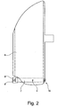
- the separator 6 has, as in the FIGS. 1 and 2 to see a board 7 up.
- the Fig. 2 shows the separator in side view.
- the circuit board 7 is arranged in the lower region of the separator 6. That is, the circuit board 7 is located at the ring bank 1 facing the end of the separator 6.
- the arrangement in the lower part of the separator 6 is due to the required proximity to the spinning ring 2.
- the board 7 has two microphones 4 and 5, which are each arranged so that they point in the direction of a spinning ring.
- the microphones 4, 5 detect the movement of the ring traveler 3. When the motion signal is absent, a thread break can be concluded. Since the movement of two adjacent ring rotors can be detected by means of the illustrated board, only every second separator 8 is equipped with a board 7 in the illustrated embodiment.
- the circuit board 7 also has an evaluation unit, not shown.
- the board 7 can be connected via terminals 10 to a power supply and to the central control unit of the ring spinning machine. Further, an LED 8 is arranged on the operator-facing side of the board, which serves as a display means.
- the evaluation unit evaluates the signals of the two microphones 4 and 5. When the elimination of the movement of one of the two ring rotors is detected, the LED lights up and indicates a thread breakage to the operator. In the present embodiment, therefore, two spinning stations share an LED 8.
- the board 7 is embedded in a slot of the separator 6.
- the separator 6 thus serves at the same time as a housing for the circuit board 7 and thus protects the microphones 4 and 5.
- a small opening is provided on the side surfaces of the separator 6 through which the sound can pass.
- An opening for the LED 8 is provided on the front side of the separator facing the operator.
- a transparent cover 9 is provided for the LED 8. At the opposite Side, ie on the rear side facing away from the operator, exit the terminals 10 of the board 7.
- the inventive arrangement maintenance work on the spinning ring 2 are not hindered.
- the ring traveler 3 can easily be exchanged or yarn breaks can be carried out without affecting the sensor 4, 5.
- the sensor 4, 5 is protected by the separators 6.
Landscapes
- Engineering & Computer Science (AREA)
- Mechanical Engineering (AREA)
- Textile Engineering (AREA)
- Spinning Or Twisting Of Yarns (AREA)
Applications Claiming Priority (1)
| Application Number | Priority Date | Filing Date | Title |
|---|---|---|---|
| DE102013011921.9A DE102013011921A1 (de) | 2013-07-17 | 2013-07-17 | Ringspinnmaschine mit einem Sensor zur Detektion der Bewegung des Ringläufers |
Related Parent Applications (1)
| Application Number | Title | Priority Date | Filing Date |
|---|---|---|---|
| DE102013011921 Previously-Filed-Application | 2013-07-17 |
Publications (2)
| Publication Number | Publication Date |
|---|---|
| EP2826899A1 EP2826899A1 (de) | 2015-01-21 |
| EP2826899B1 true EP2826899B1 (de) | 2018-02-21 |
Family
ID=50841543
Family Applications (1)
| Application Number | Title | Priority Date | Filing Date |
|---|---|---|---|
| EP14001833.4A Active EP2826899B1 (de) | 2013-07-17 | 2014-05-27 | Ringspinnmaschine mit einem Sensor zur Detektion der Bewegung des Ringläufers |
Country Status (6)
| Country | Link |
|---|---|
| EP (1) | EP2826899B1 (enExample) |
| JP (1) | JP6651284B2 (enExample) |
| CN (1) | CN104294427B (enExample) |
| DE (1) | DE102013011921A1 (enExample) |
| ES (1) | ES2661637T3 (enExample) |
| IN (1) | IN2014MU01995A (enExample) |
Cited By (1)
| Publication number | Priority date | Publication date | Assignee | Title |
|---|---|---|---|---|
| EP3978662A1 (de) | 2020-10-05 | 2022-04-06 | RAFI GmbH & Co. KG | Vorrichtung zur herstellung eines fadens aus einem garn |
Families Citing this family (6)
| Publication number | Priority date | Publication date | Assignee | Title |
|---|---|---|---|---|
| CN107201577B (zh) * | 2017-07-12 | 2022-12-06 | 上海兰宝传感科技股份有限公司 | 高分辨率细纱机纱线恒张力检测系统及方法 |
| CN107287706A (zh) * | 2017-07-16 | 2017-10-24 | 经纬纺织机械股份有限公司 | 纺织用的隔纱板及其应用的高速环锭细纱机 |
| CN107385581B (zh) * | 2017-09-11 | 2022-10-04 | 上海兰宝传感科技股份有限公司 | 一种细纱机钢丝圈转速检测装置 |
| DE102018100362A1 (de) * | 2018-01-09 | 2019-07-11 | Maschinenfabrik Rieter Ag | Verfahren zum Steuern von Anzeigen einer Spinn- oder Spulmaschine |
| CH715908A1 (de) * | 2019-03-07 | 2020-09-15 | Rieter Ag Maschf | Verfahren zur Herstellung von Garn mit einer Ringspinnmaschine und Ringspinnmaschine. |
| CN110485011B (zh) * | 2019-09-30 | 2021-08-03 | 常州宏大智能装备产业发展研究院有限公司 | 环锭纺细纱机成纱卷绕机构运行状态在线监测方法 |
Family Cites Families (8)
| Publication number | Priority date | Publication date | Assignee | Title |
|---|---|---|---|---|
| US3523413A (en) * | 1968-02-19 | 1970-08-11 | Parks Cramer Co | Apparatus and method for detecting and reporting ends down on textile machines |
| JPS6023322Y2 (ja) * | 1981-10-29 | 1985-07-11 | 豊和工業株式会社 | 精紡機等の糸切れ監視装置 |
| CH671040A5 (enExample) | 1985-04-17 | 1989-07-31 | Zinser Textilmaschinen Gmbh | |
| IT1238996B (it) * | 1990-02-14 | 1993-09-17 | Zugnago Tessile | Dispositivo di controllo presenza filo per filatoi |
| DD293152A5 (de) | 1990-03-07 | 1991-08-22 | Textimaforschung Malimo Karl-Marx-Stadt,De | Vorrichtung zur ermittlung von fadenbruch an einer ringspinn- oder zwirnmaschine |
| EP1052314B1 (de) | 1999-05-06 | 2004-03-17 | Maschinenfabrik Rieter Ag | Sensorik für Ringspinnmaschine |
| WO2004015179A1 (de) * | 2002-08-13 | 2004-02-19 | Maschinenfabrik Rieter Ag | Sensorik für ringspinnmaschine |
| CN102995193B (zh) * | 2012-11-13 | 2016-01-13 | 天津工业大学 | 一种细纱断头检测方法及应用该方法的细纱断头检测装置 |
-
2013
- 2013-07-17 DE DE102013011921.9A patent/DE102013011921A1/de not_active Withdrawn
-
2014
- 2014-05-27 ES ES14001833.4T patent/ES2661637T3/es active Active
- 2014-05-27 EP EP14001833.4A patent/EP2826899B1/de active Active
- 2014-06-20 IN IN1995MU2014 patent/IN2014MU01995A/en unknown
- 2014-07-15 CN CN201410339291.7A patent/CN104294427B/zh active Active
- 2014-07-16 JP JP2014145859A patent/JP6651284B2/ja active Active
Non-Patent Citations (1)
| Title |
|---|
| None * |
Cited By (2)
| Publication number | Priority date | Publication date | Assignee | Title |
|---|---|---|---|---|
| EP3978662A1 (de) | 2020-10-05 | 2022-04-06 | RAFI GmbH & Co. KG | Vorrichtung zur herstellung eines fadens aus einem garn |
| EP4245900A2 (de) | 2020-10-05 | 2023-09-20 | RAFI GmbH & Co. KG | Vorrichtung zur herstellung eines fadens aus einem garn |
Also Published As
| Publication number | Publication date |
|---|---|
| IN2014MU01995A (enExample) | 2015-10-16 |
| CN104294427B (zh) | 2017-09-01 |
| EP2826899A1 (de) | 2015-01-21 |
| CN104294427A (zh) | 2015-01-21 |
| JP6651284B2 (ja) | 2020-02-19 |
| DE102013011921A1 (de) | 2015-01-22 |
| ES2661637T3 (es) | 2018-04-02 |
| JP2015021216A (ja) | 2015-02-02 |
Similar Documents
| Publication | Publication Date | Title |
|---|---|---|
| EP2826899B1 (de) | Ringspinnmaschine mit einem Sensor zur Detektion der Bewegung des Ringläufers | |
| DE102014018628A1 (de) | Vielstellentextilmaschine | |
| DE102014110647B4 (de) | Fadenzuführvorrichtung und Verfahren zum Zuführen von Fäden zu einer Rundstrickmaschine mit Ringelapparaten | |
| DE102008000610B4 (de) | Sensor für eine Textilmaschine | |
| DE10344163B9 (de) | Verfahren und Vorrichtung zur Herstellung von Coregarn oder Corescheinzwirn | |
| DE2607882C3 (de) | Spinnmaschine mit einer Vorrichtung zum Unterbrechen der Vorgarnzufuhr zu den Streckwerken bei Fadenbruch | |
| DE4338453C2 (de) | Paraffiniereinrichtung | |
| DE19548232C5 (de) | Verfahren und Vorrichtung zum Trennen eines Faserbandes beim Kannenwechsel an einer Strecke | |
| EP2682509B1 (de) | Streckwerk für eine Spinnmaschine | |
| DE1097869B (de) | Fadenwaechter | |
| DE4122305B4 (de) | Vorrichtung zur optoelektronischen Abtastung eines Fadens | |
| DE10255382A1 (de) | Textilmaschine mit wenigstens einer Entstaubungsvorrichtung | |
| DE1939364C3 (de) | Verfahren und Vorrichtung zum Feststellen von Fadenbriichen bei Textilmaschinen | |
| DE102016003815A1 (de) | Vorrichtung zur Justierung einer Andrückwalze | |
| EP2746439B1 (en) | Means for application of polymer solution on cord spinning electrode | |
| DE102006062364B4 (de) | Vorrichtung zum Herstellen einer Maschenware | |
| EP2076620B1 (de) | Fadenliefergerät | |
| EP0931865A1 (de) | Schussfadenstreck- und -detektiereinrichtung für Düsenwebmaschinen, insbesondere mit pneumatischem Schusseintrag | |
| DE102012213370B3 (de) | Vorrichtung zur Präsentation von Brillen | |
| EP2304088A1 (de) | Kapazitiv arbeitende sensoreinheit zur überwachung der qualität von fasermaterial und damit ausgerüstete maschine zur herstellung von maschenware | |
| EP1561845A2 (de) | Verfahren zum Überwachen des Kernelements beim Herstellen von Core-Garn | |
| DE1939363A1 (de) | Einrichtung zum Anzeigen von Fadenbruechen bei einer Textilmaschine | |
| DE2924938A1 (de) | Vorrichtung zum ueberpruefen der funktion einer aufloesewalze eines offenend- spinnaggregates | |
| EP3184677B1 (de) | Spindelanordnung und ringspinnmaschine mit der spindelanordnung | |
| EP2599905B1 (de) | Deckelelement einer Offenend-Spinnvorrichtung zum Verschließen eines besaugten, nach vorne hin offenen Rotorgehäuses |
Legal Events
| Date | Code | Title | Description |
|---|---|---|---|
| 17P | Request for examination filed |
Effective date: 20140527 |
|
| AK | Designated contracting states |
Kind code of ref document: A1 Designated state(s): AL AT BE BG CH CY CZ DE DK EE ES FI FR GB GR HR HU IE IS IT LI LT LU LV MC MK MT NL NO PL PT RO RS SE SI SK SM TR |
|
| AX | Request for extension of the european patent |
Extension state: BA ME |
|
| PUAI | Public reference made under article 153(3) epc to a published international application that has entered the european phase |
Free format text: ORIGINAL CODE: 0009012 |
|
| R17P | Request for examination filed (corrected) |
Effective date: 20150721 |
|
| RBV | Designated contracting states (corrected) |
Designated state(s): AL AT BE BG CH CY CZ DE DK EE ES FI FR GB GR HR HU IE IS IT LI LT LU LV MC MK MT NL NO PL PT RO RS SE SI SK SM TR |
|
| 17Q | First examination report despatched |
Effective date: 20160620 |
|
| GRAP | Despatch of communication of intention to grant a patent |
Free format text: ORIGINAL CODE: EPIDOSNIGR1 |
|
| GRAJ | Information related to disapproval of communication of intention to grant by the applicant or resumption of examination proceedings by the epo deleted |
Free format text: ORIGINAL CODE: EPIDOSDIGR1 |
|
| INTG | Intention to grant announced |
Effective date: 20171018 |
|
| GRAP | Despatch of communication of intention to grant a patent |
Free format text: ORIGINAL CODE: EPIDOSNIGR1 |
|
| INTC | Intention to grant announced (deleted) | ||
| GRAS | Grant fee paid |
Free format text: ORIGINAL CODE: EPIDOSNIGR3 |
|
| INTG | Intention to grant announced |
Effective date: 20171220 |
|
| GRAA | (expected) grant |
Free format text: ORIGINAL CODE: 0009210 |
|
| AK | Designated contracting states |
Kind code of ref document: B1 Designated state(s): AL AT BE BG CH CY CZ DE DK EE ES FI FR GB GR HR HU IE IS IT LI LT LU LV MC MK MT NL NO PL PT RO RS SE SI SK SM TR |
|
| REG | Reference to a national code |
Ref country code: GB Ref legal event code: FG4D Free format text: NOT ENGLISH |
|
| REG | Reference to a national code |
Ref country code: CH Ref legal event code: EP |
|
| REG | Reference to a national code |
Ref country code: AT Ref legal event code: REF Ref document number: 971827 Country of ref document: AT Kind code of ref document: T Effective date: 20180315 |
|
| REG | Reference to a national code |
Ref country code: IE Ref legal event code: FG4D Free format text: LANGUAGE OF EP DOCUMENT: GERMAN |
|
| REG | Reference to a national code |
Ref country code: DE Ref legal event code: R096 Ref document number: 502014007287 Country of ref document: DE |
|
| REG | Reference to a national code |
Ref country code: ES Ref legal event code: FG2A Ref document number: 2661637 Country of ref document: ES Kind code of ref document: T3 Effective date: 20180402 |
|
| REG | Reference to a national code |
Ref country code: NL Ref legal event code: MP Effective date: 20180221 |
|
| REG | Reference to a national code |
Ref country code: LT Ref legal event code: MG4D |
|
| PG25 | Lapsed in a contracting state [announced via postgrant information from national office to epo] |
Ref country code: HR Free format text: LAPSE BECAUSE OF FAILURE TO SUBMIT A TRANSLATION OF THE DESCRIPTION OR TO PAY THE FEE WITHIN THE PRESCRIBED TIME-LIMIT Effective date: 20180221 Ref country code: NL Free format text: LAPSE BECAUSE OF FAILURE TO SUBMIT A TRANSLATION OF THE DESCRIPTION OR TO PAY THE FEE WITHIN THE PRESCRIBED TIME-LIMIT Effective date: 20180221 Ref country code: CY Free format text: LAPSE BECAUSE OF FAILURE TO SUBMIT A TRANSLATION OF THE DESCRIPTION OR TO PAY THE FEE WITHIN THE PRESCRIBED TIME-LIMIT Effective date: 20180221 Ref country code: NO Free format text: LAPSE BECAUSE OF FAILURE TO SUBMIT A TRANSLATION OF THE DESCRIPTION OR TO PAY THE FEE WITHIN THE PRESCRIBED TIME-LIMIT Effective date: 20180521 Ref country code: FI Free format text: LAPSE BECAUSE OF FAILURE TO SUBMIT A TRANSLATION OF THE DESCRIPTION OR TO PAY THE FEE WITHIN THE PRESCRIBED TIME-LIMIT Effective date: 20180221 Ref country code: LT Free format text: LAPSE BECAUSE OF FAILURE TO SUBMIT A TRANSLATION OF THE DESCRIPTION OR TO PAY THE FEE WITHIN THE PRESCRIBED TIME-LIMIT Effective date: 20180221 |
|
| PG25 | Lapsed in a contracting state [announced via postgrant information from national office to epo] |
Ref country code: SE Free format text: LAPSE BECAUSE OF FAILURE TO SUBMIT A TRANSLATION OF THE DESCRIPTION OR TO PAY THE FEE WITHIN THE PRESCRIBED TIME-LIMIT Effective date: 20180221 Ref country code: LV Free format text: LAPSE BECAUSE OF FAILURE TO SUBMIT A TRANSLATION OF THE DESCRIPTION OR TO PAY THE FEE WITHIN THE PRESCRIBED TIME-LIMIT Effective date: 20180221 Ref country code: RS Free format text: LAPSE BECAUSE OF FAILURE TO SUBMIT A TRANSLATION OF THE DESCRIPTION OR TO PAY THE FEE WITHIN THE PRESCRIBED TIME-LIMIT Effective date: 20180221 Ref country code: BG Free format text: LAPSE BECAUSE OF FAILURE TO SUBMIT A TRANSLATION OF THE DESCRIPTION OR TO PAY THE FEE WITHIN THE PRESCRIBED TIME-LIMIT Effective date: 20180521 Ref country code: GR Free format text: LAPSE BECAUSE OF FAILURE TO SUBMIT A TRANSLATION OF THE DESCRIPTION OR TO PAY THE FEE WITHIN THE PRESCRIBED TIME-LIMIT Effective date: 20180522 |
|
| REG | Reference to a national code |
Ref country code: DE Ref legal event code: R081 Ref document number: 502014007287 Country of ref document: DE Owner name: SAURER SPINNING SOLUTIONS GMBH & CO. KG, DE Free format text: FORMER OWNER: SAURER GERMANY GMBH & CO. KG, 42897 REMSCHEID, DE |
|
| PG25 | Lapsed in a contracting state [announced via postgrant information from national office to epo] |
Ref country code: MT Free format text: LAPSE BECAUSE OF FAILURE TO SUBMIT A TRANSLATION OF THE DESCRIPTION OR TO PAY THE FEE WITHIN THE PRESCRIBED TIME-LIMIT Effective date: 20180221 |
|
| RAP2 | Party data changed (patent owner data changed or rights of a patent transferred) |
Owner name: SAURER SPINNING SOLUTIONS GMBH & CO. KG |
|
| PG25 | Lapsed in a contracting state [announced via postgrant information from national office to epo] |
Ref country code: AL Free format text: LAPSE BECAUSE OF FAILURE TO SUBMIT A TRANSLATION OF THE DESCRIPTION OR TO PAY THE FEE WITHIN THE PRESCRIBED TIME-LIMIT Effective date: 20180221 Ref country code: RO Free format text: LAPSE BECAUSE OF FAILURE TO SUBMIT A TRANSLATION OF THE DESCRIPTION OR TO PAY THE FEE WITHIN THE PRESCRIBED TIME-LIMIT Effective date: 20180221 Ref country code: EE Free format text: LAPSE BECAUSE OF FAILURE TO SUBMIT A TRANSLATION OF THE DESCRIPTION OR TO PAY THE FEE WITHIN THE PRESCRIBED TIME-LIMIT Effective date: 20180221 Ref country code: PL Free format text: LAPSE BECAUSE OF FAILURE TO SUBMIT A TRANSLATION OF THE DESCRIPTION OR TO PAY THE FEE WITHIN THE PRESCRIBED TIME-LIMIT Effective date: 20180221 |
|
| REG | Reference to a national code |
Ref country code: DE Ref legal event code: R097 Ref document number: 502014007287 Country of ref document: DE |
|
| PG25 | Lapsed in a contracting state [announced via postgrant information from national office to epo] |
Ref country code: SM Free format text: LAPSE BECAUSE OF FAILURE TO SUBMIT A TRANSLATION OF THE DESCRIPTION OR TO PAY THE FEE WITHIN THE PRESCRIBED TIME-LIMIT Effective date: 20180221 Ref country code: SK Free format text: LAPSE BECAUSE OF FAILURE TO SUBMIT A TRANSLATION OF THE DESCRIPTION OR TO PAY THE FEE WITHIN THE PRESCRIBED TIME-LIMIT Effective date: 20180221 Ref country code: DK Free format text: LAPSE BECAUSE OF FAILURE TO SUBMIT A TRANSLATION OF THE DESCRIPTION OR TO PAY THE FEE WITHIN THE PRESCRIBED TIME-LIMIT Effective date: 20180221 Ref country code: CZ Free format text: LAPSE BECAUSE OF FAILURE TO SUBMIT A TRANSLATION OF THE DESCRIPTION OR TO PAY THE FEE WITHIN THE PRESCRIBED TIME-LIMIT Effective date: 20180221 |
|
| PLBE | No opposition filed within time limit |
Free format text: ORIGINAL CODE: 0009261 |
|
| STAA | Information on the status of an ep patent application or granted ep patent |
Free format text: STATUS: NO OPPOSITION FILED WITHIN TIME LIMIT |
|
| 26N | No opposition filed |
Effective date: 20181122 |
|
| GBPC | Gb: european patent ceased through non-payment of renewal fee |
Effective date: 20180527 |
|
| REG | Reference to a national code |
Ref country code: BE Ref legal event code: MM Effective date: 20180531 |
|
| PG25 | Lapsed in a contracting state [announced via postgrant information from national office to epo] |
Ref country code: MC Free format text: LAPSE BECAUSE OF FAILURE TO SUBMIT A TRANSLATION OF THE DESCRIPTION OR TO PAY THE FEE WITHIN THE PRESCRIBED TIME-LIMIT Effective date: 20180221 |
|
| REG | Reference to a national code |
Ref country code: IE Ref legal event code: MM4A |
|
| PG25 | Lapsed in a contracting state [announced via postgrant information from national office to epo] |
Ref country code: SI Free format text: LAPSE BECAUSE OF FAILURE TO SUBMIT A TRANSLATION OF THE DESCRIPTION OR TO PAY THE FEE WITHIN THE PRESCRIBED TIME-LIMIT Effective date: 20180221 |
|
| PG25 | Lapsed in a contracting state [announced via postgrant information from national office to epo] |
Ref country code: LU Free format text: LAPSE BECAUSE OF NON-PAYMENT OF DUE FEES Effective date: 20180527 |
|
| PG25 | Lapsed in a contracting state [announced via postgrant information from national office to epo] |
Ref country code: GB Free format text: LAPSE BECAUSE OF NON-PAYMENT OF DUE FEES Effective date: 20180527 Ref country code: IE Free format text: LAPSE BECAUSE OF NON-PAYMENT OF DUE FEES Effective date: 20180527 Ref country code: FR Free format text: LAPSE BECAUSE OF NON-PAYMENT OF DUE FEES Effective date: 20180531 |
|
| PG25 | Lapsed in a contracting state [announced via postgrant information from national office to epo] |
Ref country code: BE Free format text: LAPSE BECAUSE OF NON-PAYMENT OF DUE FEES Effective date: 20180531 |
|
| PG25 | Lapsed in a contracting state [announced via postgrant information from national office to epo] |
Ref country code: HU Free format text: LAPSE BECAUSE OF FAILURE TO SUBMIT A TRANSLATION OF THE DESCRIPTION OR TO PAY THE FEE WITHIN THE PRESCRIBED TIME-LIMIT; INVALID AB INITIO Effective date: 20140527 Ref country code: PT Free format text: LAPSE BECAUSE OF FAILURE TO SUBMIT A TRANSLATION OF THE DESCRIPTION OR TO PAY THE FEE WITHIN THE PRESCRIBED TIME-LIMIT Effective date: 20180221 |
|
| PG25 | Lapsed in a contracting state [announced via postgrant information from national office to epo] |
Ref country code: MK Free format text: LAPSE BECAUSE OF NON-PAYMENT OF DUE FEES Effective date: 20180221 |
|
| PG25 | Lapsed in a contracting state [announced via postgrant information from national office to epo] |
Ref country code: IS Free format text: LAPSE BECAUSE OF FAILURE TO SUBMIT A TRANSLATION OF THE DESCRIPTION OR TO PAY THE FEE WITHIN THE PRESCRIBED TIME-LIMIT Effective date: 20180621 |
|
| REG | Reference to a national code |
Ref country code: AT Ref legal event code: MM01 Ref document number: 971827 Country of ref document: AT Kind code of ref document: T Effective date: 20190527 |
|
| PG25 | Lapsed in a contracting state [announced via postgrant information from national office to epo] |
Ref country code: AT Free format text: LAPSE BECAUSE OF NON-PAYMENT OF DUE FEES Effective date: 20190527 |
|
| PGFP | Annual fee paid to national office [announced via postgrant information from national office to epo] |
Ref country code: DE Payment date: 20250519 Year of fee payment: 12 |
|
| PGFP | Annual fee paid to national office [announced via postgrant information from national office to epo] |
Ref country code: ES Payment date: 20250616 Year of fee payment: 12 |
|
| PGFP | Annual fee paid to national office [announced via postgrant information from national office to epo] |
Ref country code: IT Payment date: 20250530 Year of fee payment: 12 |
|
| PGFP | Annual fee paid to national office [announced via postgrant information from national office to epo] |
Ref country code: CH Payment date: 20250601 Year of fee payment: 12 |
|
| PGFP | Annual fee paid to national office [announced via postgrant information from national office to epo] |
Ref country code: TR Payment date: 20250520 Year of fee payment: 12 |