EP2825793B1 - Device and method for controlling transmission torque to provide hill ascent and/or descent assistance - Google Patents
Device and method for controlling transmission torque to provide hill ascent and/or descent assistance Download PDFInfo
- Publication number
- EP2825793B1 EP2825793B1 EP13760667.9A EP13760667A EP2825793B1 EP 2825793 B1 EP2825793 B1 EP 2825793B1 EP 13760667 A EP13760667 A EP 13760667A EP 2825793 B1 EP2825793 B1 EP 2825793B1
- Authority
- EP
- European Patent Office
- Prior art keywords
- throttle
- threshold
- brake
- signal
- clutch
- Prior art date
- Legal status (The legal status is an assumption and is not a legal conclusion. Google has not performed a legal analysis and makes no representation as to the accuracy of the status listed.)
- Active
Links
- 230000005540 biological transmission Effects 0.000 title claims description 233
- 238000000034 method Methods 0.000 title description 75
- 230000004044 response Effects 0.000 claims description 49
- 230000006870 function Effects 0.000 claims description 16
- 238000006073 displacement reaction Methods 0.000 description 9
- 238000005096 rolling process Methods 0.000 description 7
- 230000007423 decrease Effects 0.000 description 6
- 230000008569 process Effects 0.000 description 6
- 230000001133 acceleration Effects 0.000 description 4
- 238000004891 communication Methods 0.000 description 4
- 238000010586 diagram Methods 0.000 description 3
- 238000012986 modification Methods 0.000 description 3
- 230000004048 modification Effects 0.000 description 3
- 238000002485 combustion reaction Methods 0.000 description 2
- 230000003247 decreasing effect Effects 0.000 description 2
- 230000000694 effects Effects 0.000 description 2
- 230000007613 environmental effect Effects 0.000 description 2
- 238000000638 solvent extraction Methods 0.000 description 2
- 230000001360 synchronised effect Effects 0.000 description 2
- 238000012546 transfer Methods 0.000 description 2
- 230000003213 activating effect Effects 0.000 description 1
- 230000008859 change Effects 0.000 description 1
- 238000013500 data storage Methods 0.000 description 1
- 230000001419 dependent effect Effects 0.000 description 1
- 239000012634 fragment Substances 0.000 description 1
- 230000010354 integration Effects 0.000 description 1
- 230000007246 mechanism Effects 0.000 description 1
- 230000007935 neutral effect Effects 0.000 description 1
- 230000003287 optical effect Effects 0.000 description 1
- 238000012545 processing Methods 0.000 description 1
- 230000009467 reduction Effects 0.000 description 1
- 238000000926 separation method Methods 0.000 description 1
- 239000007787 solid Substances 0.000 description 1
Images


Classifications
-
- F—MECHANICAL ENGINEERING; LIGHTING; HEATING; WEAPONS; BLASTING
- F16—ENGINEERING ELEMENTS AND UNITS; GENERAL MEASURES FOR PRODUCING AND MAINTAINING EFFECTIVE FUNCTIONING OF MACHINES OR INSTALLATIONS; THERMAL INSULATION IN GENERAL
- F16D—COUPLINGS FOR TRANSMITTING ROTATION; CLUTCHES; BRAKES
- F16D48/00—External control of clutches
- F16D48/06—Control by electric or electronic means, e.g. of fluid pressure
-
- F—MECHANICAL ENGINEERING; LIGHTING; HEATING; WEAPONS; BLASTING
- F16—ENGINEERING ELEMENTS AND UNITS; GENERAL MEASURES FOR PRODUCING AND MAINTAINING EFFECTIVE FUNCTIONING OF MACHINES OR INSTALLATIONS; THERMAL INSULATION IN GENERAL
- F16H—GEARING
- F16H61/00—Control functions within control units of change-speed- or reversing-gearings for conveying rotary motion ; Control of exclusively fluid gearing, friction gearing, gearings with endless flexible members or other particular types of gearing
- F16H61/0059—Braking of gear output shaft using simultaneous engagement of friction devices applied for different gear ratios
-
- F—MECHANICAL ENGINEERING; LIGHTING; HEATING; WEAPONS; BLASTING
- F16—ENGINEERING ELEMENTS AND UNITS; GENERAL MEASURES FOR PRODUCING AND MAINTAINING EFFECTIVE FUNCTIONING OF MACHINES OR INSTALLATIONS; THERMAL INSULATION IN GENERAL
- F16H—GEARING
- F16H61/00—Control functions within control units of change-speed- or reversing-gearings for conveying rotary motion ; Control of exclusively fluid gearing, friction gearing, gearings with endless flexible members or other particular types of gearing
- F16H61/20—Preventing gear creeping ; Transmission control during standstill, e.g. hill hold control
-
- B—PERFORMING OPERATIONS; TRANSPORTING
- B60—VEHICLES IN GENERAL
- B60W—CONJOINT CONTROL OF VEHICLE SUB-UNITS OF DIFFERENT TYPE OR DIFFERENT FUNCTION; CONTROL SYSTEMS SPECIALLY ADAPTED FOR HYBRID VEHICLES; ROAD VEHICLE DRIVE CONTROL SYSTEMS FOR PURPOSES NOT RELATED TO THE CONTROL OF A PARTICULAR SUB-UNIT
- B60W10/00—Conjoint control of vehicle sub-units of different type or different function
- B60W10/02—Conjoint control of vehicle sub-units of different type or different function including control of driveline clutches
-
- B—PERFORMING OPERATIONS; TRANSPORTING
- B60—VEHICLES IN GENERAL
- B60W—CONJOINT CONTROL OF VEHICLE SUB-UNITS OF DIFFERENT TYPE OR DIFFERENT FUNCTION; CONTROL SYSTEMS SPECIALLY ADAPTED FOR HYBRID VEHICLES; ROAD VEHICLE DRIVE CONTROL SYSTEMS FOR PURPOSES NOT RELATED TO THE CONTROL OF A PARTICULAR SUB-UNIT
- B60W10/00—Conjoint control of vehicle sub-units of different type or different function
- B60W10/04—Conjoint control of vehicle sub-units of different type or different function including control of propulsion units
- B60W10/06—Conjoint control of vehicle sub-units of different type or different function including control of propulsion units including control of combustion engines
-
- B—PERFORMING OPERATIONS; TRANSPORTING
- B60—VEHICLES IN GENERAL
- B60W—CONJOINT CONTROL OF VEHICLE SUB-UNITS OF DIFFERENT TYPE OR DIFFERENT FUNCTION; CONTROL SYSTEMS SPECIALLY ADAPTED FOR HYBRID VEHICLES; ROAD VEHICLE DRIVE CONTROL SYSTEMS FOR PURPOSES NOT RELATED TO THE CONTROL OF A PARTICULAR SUB-UNIT
- B60W30/00—Purposes of road vehicle drive control systems not related to the control of a particular sub-unit, e.g. of systems using conjoint control of vehicle sub-units
- B60W30/18—Propelling the vehicle
-
- F—MECHANICAL ENGINEERING; LIGHTING; HEATING; WEAPONS; BLASTING
- F16—ENGINEERING ELEMENTS AND UNITS; GENERAL MEASURES FOR PRODUCING AND MAINTAINING EFFECTIVE FUNCTIONING OF MACHINES OR INSTALLATIONS; THERMAL INSULATION IN GENERAL
- F16H—GEARING
- F16H61/00—Control functions within control units of change-speed- or reversing-gearings for conveying rotary motion ; Control of exclusively fluid gearing, friction gearing, gearings with endless flexible members or other particular types of gearing
- F16H61/20—Preventing gear creeping ; Transmission control during standstill, e.g. hill hold control
- F16H2061/205—Hill hold control, e.g. with torque converter or a friction device slightly engaged to keep vehicle stationary
-
- F—MECHANICAL ENGINEERING; LIGHTING; HEATING; WEAPONS; BLASTING
- F16—ENGINEERING ELEMENTS AND UNITS; GENERAL MEASURES FOR PRODUCING AND MAINTAINING EFFECTIVE FUNCTIONING OF MACHINES OR INSTALLATIONS; THERMAL INSULATION IN GENERAL
- F16H—GEARING
- F16H61/00—Control functions within control units of change-speed- or reversing-gearings for conveying rotary motion ; Control of exclusively fluid gearing, friction gearing, gearings with endless flexible members or other particular types of gearing
- F16H61/0003—Arrangement or mounting of elements of the control apparatus, e.g. valve assemblies or snapfittings of valves; Arrangements of the control unit on or in the transmission gearbox
- F16H61/0009—Hydraulic control units for transmission control, e.g. assembly of valve plates or valve units
-
- F—MECHANICAL ENGINEERING; LIGHTING; HEATING; WEAPONS; BLASTING
- F16—ENGINEERING ELEMENTS AND UNITS; GENERAL MEASURES FOR PRODUCING AND MAINTAINING EFFECTIVE FUNCTIONING OF MACHINES OR INSTALLATIONS; THERMAL INSULATION IN GENERAL
- F16H—GEARING
- F16H61/00—Control functions within control units of change-speed- or reversing-gearings for conveying rotary motion ; Control of exclusively fluid gearing, friction gearing, gearings with endless flexible members or other particular types of gearing
- F16H61/02—Control functions within control units of change-speed- or reversing-gearings for conveying rotary motion ; Control of exclusively fluid gearing, friction gearing, gearings with endless flexible members or other particular types of gearing characterised by the signals used
- F16H61/0202—Control functions within control units of change-speed- or reversing-gearings for conveying rotary motion ; Control of exclusively fluid gearing, friction gearing, gearings with endless flexible members or other particular types of gearing characterised by the signals used the signals being electric
- F16H61/0204—Control functions within control units of change-speed- or reversing-gearings for conveying rotary motion ; Control of exclusively fluid gearing, friction gearing, gearings with endless flexible members or other particular types of gearing characterised by the signals used the signals being electric for gearshift control, e.g. control functions for performing shifting or generation of shift signal
- F16H61/0206—Layout of electro-hydraulic control circuits, e.g. arrangement of valves
-
- F—MECHANICAL ENGINEERING; LIGHTING; HEATING; WEAPONS; BLASTING
- F16—ENGINEERING ELEMENTS AND UNITS; GENERAL MEASURES FOR PRODUCING AND MAINTAINING EFFECTIVE FUNCTIONING OF MACHINES OR INSTALLATIONS; THERMAL INSULATION IN GENERAL
- F16H—GEARING
- F16H61/00—Control functions within control units of change-speed- or reversing-gearings for conveying rotary motion ; Control of exclusively fluid gearing, friction gearing, gearings with endless flexible members or other particular types of gearing
- F16H61/66—Control functions within control units of change-speed- or reversing-gearings for conveying rotary motion ; Control of exclusively fluid gearing, friction gearing, gearings with endless flexible members or other particular types of gearing specially adapted for continuously variable gearings
Definitions
- the present disclosure relates, generally, to transmission control systems and techniques and, more specifically, to devices, systems, and methods for controlling transmission torque to provide hill ascent and/or descent control assistance.
- Transmissions are used to transfer a drive torque from a drive unit to a load.
- a vehicle transmission transfers the drive torque from the vehicle engine to the vehicle load.
- Some transmissions include a finite set of gears, which may be selected to produce a specific transmission ratio. To do so, the transmissions may include one or more clutches, which may be engaged to select one or more gear sets to produce the required transmission ratio.
- the operation of the transmission may be controlled by a transmission control module (TCM), which is often embodied as an electronic circuit.
- TCM transmission control module
- the transmission control module may select, for example, one or more gear sets by causing engagement of the corresponding clutches.
- the transmission control module may control the operation of the automatic transmission based on one or more operation signals, such as transmission operation signals and engine operation signals. Such signals may be received by the transmission control module directly from the corresponding sensors. Alternatively, some of the signals used by the transmission control module may be received indirectly from an engine control module (ECM) of the vehicle, which monitors and controls the operation of the vehicle's engine. Further, in some vehicles, the transmission control module and the engine control module may be combined into, or otherwise included in, a powertrain control module (PCM). In this way, the transmission control module and the engine control module (or powertrain control module) operate together to control and monitor the operation of the vehicle's powertrain.
- PCM powertrain control module
- EP 1 995 499 A1 describes that at the beginning (t1) of a standing declutch, a third gearshift element is closed so far that braking torque (P B 2) adjusted in a gearshift element generates a braking torque that acts upon an output shaft, lies below a possible maximum braking toque and is measured in such a way that, if a motor vehicle rolls away downhill, brakes are only applied without activating a vehicle's brake.
- the braking torque generated is compensated by fully opening the third gearshift element at the end (t2) of a standing declutch.
- US 2007/010927 A1 describes a method for controlling a power-shift transmission comprising controlling a vehicle travel speed by simultaneously slipping two or more clutch packs associated with opposing directions of vehicle travel and adjusting an engine speed, according to a programmed response associated with a change in one or more of the engine speed, a torque converter slip, a selected direction of vehicle travel, and an accelerator position.
- a transmission control module for controlling an automatic transmission of a vehicle, the transmission control module comprising:
- control circuit may further compare the transmission output speed signal to an output speed threshold, compare the throttle signal to a throttle low threshold, and compare the brake signal to a brake low threshold. In such embodiments, the control circuit may release the clutch hold pressure in response to (i) the output speed signal being greater than the output speed threshold, (ii) the throttle signal being greater than the throttle low threshold; and (iii) the brake signal being less than the brake low threshold. Additionally or alternatively, in some embodiments, the control circuit may release the clutch hold pressure in response to determining that the automatic transmission has been disengaged from a forward or a reverse gear.
- control circuit of the transmission control module may compare the brake signal to a brake high threshold, compare the throttle signal to a throttle high threshold, and apply the clutch hold pressure in response to (i) the brake signal being greater than the brake high threshold and (ii) the throttle signal being less than the throttle high threshold. Additionally or alternatively, the control circuit may compare the brake signal to a brake high threshold, compare the throttle signal to a throttle high threshold, and release the clutch hold pressure in response to (i) the brake signal being greater than the brake high threshold and (ii) the throttle signal being greater than the throttle high threshold.
- control circuit may adjust the clutch hold pressure by setting the clutch hold pressure to the product of the current clutch hold pressure and the clutch release ramp rate.
- control circuit may compare the throttle signal to a throttle low threshold and set the clutch release ramp rate to a second ramp rate in response to (i) the brake signal being less than the brake high threshold and (ii) the throttle signal being greater than the low throttle threshold and less than the throttle medium threshold.
- control circuit may increment a clutch hold timer in response to (i) the brake signal being less than the brake high threshold and (ii) the throttle signal being less than the low throttle threshold, compare the clutch hold timer to a timer threshold, and perform one of the following: (i) set the clutch release ramp rate to the second ramp rate in response to the clutch hold timer being greater than the timer threshold and (ii) maintain the clutch hold pressure at a current clutch hold pressure in response to the clutch hold timer being less than the timer threshold.
- control circuit may compare the brake signal to a brake high threshold, compare the throttle signal to a throttle low threshold and a throttle medium threshold, set a clutch release ramp rate to a second ramp rate in response to (i) the brake signal being less than the brake high threshold and (ii) the throttle signal being greater than the low throttle threshold and less than the throttle medium threshold, and adjust the clutch hold pressure as a function of the current clutch hold pressure and the clutch release ramp rate.
- control circuit may compare the brake signal to a brake high threshold, compare the throttle signal to a throttle low threshold, increment a clutch hold timer in response to (i) the brake signal being less than the brake high threshold and (ii) the throttle signal being less than the low throttle threshold, compare the clutch hold timer to a timer threshold, and perform one of the following: (i) set the clutch release ramp rate to a second ramp rate in response to the clutch hold timer being greater than the timer threshold and (ii) maintain the clutch hold pressure at a current clutch hold pressure in response to the clutch hold timer being less than the timer threshold.
- a method for controlling an automatic transmission of a vehicle may include receiving a transmission output speed signal indicative of a rotational output speed of the automatic transmission, receiving a throttle signal indicative of application of a throttle of the vehicle, and/or receiving a brake signal indicative of application of a brake of the vehicle. Additionally, the method may include applying a clutch hold pressure to at least one clutch of the automatic transmission as a function of (i) the transmission output speed signal, (ii) the throttle signal, and (ii) the brake signal, the clutch hold pressure having a magnitude sufficient to lock an output shaft of the automatic transmission to resist roll-back of the vehicle.
- the method may include comparing the transmission output speed signal to an output speed threshold, comparing the throttle signal to a throttle low threshold, comparing the brake signal to a brake low threshold, and releasing the clutch hold pressure in response (i) the output speed signal being greater than the output speed threshold, (ii) the throttle signal being greater than the throttle low threshold; and (iii) the brake signal being less than the brake low threshold. Additionally or alternatively, the may include releasing the clutch hold pressure in response to determining that the automatic transmission has been disengaged from a forward or a reverse gear.
- Applying the clutch hold pressure may include comparing the brake signal to a brake high threshold, comparing the throttle signal to a throttle high threshold, and applying the clutch hold pressure in response to (i) the brake signal being greater than the brake high threshold and (ii) the throttle signal being less than the throttle high threshold. Additionally, the method may include comparing the brake signal to a brake high threshold, comparing the throttle signal to a throttle high threshold, and releasing the clutch hold pressure in response to (i) the brake signal being greater than the brake high threshold and (ii) the throttle signal being greater than the throttle high threshold.
- the method may include comparing the brake signal to a brake high threshold, comparing the throttle signal to a throttle high threshold and a throttle medium threshold, setting a clutch release ramp rate to a high ramp rate in response to (i) the brake signal being less than the brake high threshold and (ii) the throttle signal being greater than the throttle medium threshold and less than the throttle high threshold, and adjusting the clutch hold pressure as a function of the current clutch hold pressure and the clutch release ramp rate.
- adjusting the clutch hold pressure may include setting the clutch hold pressure to the product of the current clutch hold pressure and the clutch release ramp rate.
- the method may further include comparing the throttle signal to a throttle low threshold and setting the clutch release ramp rate to a low ramp rate in response to (i) the brake signal being less than the brake high threshold and (ii) the throttle signal being greater than the low throttle threshold and less than the throttle medium threshold.
- the method may include incrementing a clutch hold timer in response to (i) the brake signal being less than the brake high threshold and (ii) the throttle signal being less than the low throttle threshold, comparing the clutch hold timer to a timer threshold, and performing one of the following: setting the clutch release ramp rate to the low ramp rate in response to the clutch hold timer being greater than the timer threshold and (ii) maintaining the clutch hold pressure at a current clutch hold pressure in response to the clutch hold timer being less than the timer threshold.
- the method may include comparing the brake signal to a brake high threshold, comparing the throttle signal to a throttle low threshold and a throttle medium threshold, setting a clutch release ramp rate to a low ramp rate in response to (i) the brake signal being less than the brake high threshold and (ii) the throttle signal being greater than the low throttle threshold and less than the throttle medium threshold, and adjusting the clutch hold pressure as a function of the current clutch hold pressure and the clutch release ramp rate.
- the method may include comparing the brake signal to a brake high threshold, comparing the throttle signal to a throttle low threshold, incrementing a clutch hold timer in response to (i) the brake signal being less than the brake high threshold and (ii) the throttle signal being less than the low throttle threshold, comparing the clutch hold timer to a timer threshold, and performing one of the following: (i) setting the clutch release ramp rate to the low ramp rate in response to the clutch hold timer being greater than the timer threshold and (ii) maintaining the clutch hold pressure at a current clutch hold pressure in response to the clutch hold timer being less than the timer threshold.
- Receiving the transmission output speed signal may include receiving a transmission output speed signal from a transmission output sensor of the automatic transmission.
- receiving the throttle signal may include receiving a throttle signal from a throttle sensor of the vehicle.
- receiving the throttle signal may include receiving a throttle signal from an engine control module of the vehicle. Further, the throttle signal may be indicative of a percentage of throttle displacement relative to a maximum throttle.
- receiving the brake signal may include receiving the brake signal from a brake sensor of the vehicle.
- receiving the brake signal may include receiving a brake signal from an engine control module of the vehicle.
- the brake signal may be indicative of a percentage of brake displacement relative to a maximum braking.
- a system for controlling an automatic transmission of a vehicle may comprise a transmission output speed sensor, a throttle sensor, a brake sensor, and a transmission control module.
- the transmission output speed sensor may be coupled to the automatic transmission and configured to generate a transmission output speed signal indicative of a rotational output speed of the automatic transmission.
- the throttle sensor may be configured to generate a throttle signal indicative of application of a throttle of the vehicle, and the brake sensor may be configured to generate a brake signal indicative of application of a brake of the vehicle.
- the transmission control module may be configured to generate a clutch control signal to cause application of a clutch hold pressure to at least one clutch of the automatic transmission as a function of (i) the transmission output speed signal, (ii) the throttle signal, and (ii) the brake signal.
- the clutch hold pressure may have a magnitude sufficient to lock an output shaft of the automatic transmission to resist roll-back of the vehicle.
- the transmission control module may be configured to compare the transmission output speed signal to an output speed threshold, compare the throttle signal to a throttle low threshold, and compare the brake signal to a brake low threshold.
- the transmission control module may be configured to generate a clutch control signal to release the clutch hold pressure in response to (i) the output speed signal being greater than the output speed threshold, (ii) the throttle signal being greater than the throttle low threshold; and (iii) the brake signal being less than the brake low threshold. Additionally or alternatively, the transmission control module may be configured to generate a clutch control signal to release the clutch hold pressure in response to determining that the automatic transmission has been disengaged from a forward or a reverse gear.
- the transmission control module may be configured to compare the brake signal to a brake high threshold, compare the throttle signal to a throttle high threshold, and generate a clutch control signal to cause application a clutch hold pressure in response to (i) the brake signal being greater than the brake high threshold and (ii) the throttle signal being less than the throttle high threshold. Additionally or alternatively, transmission control module may be configured to compare the brake signal to a brake high threshold, compare the throttle signal to a throttle high threshold, and generate a clutch control signal to release the clutch hold pressure in response to (i) the brake signal being greater than the brake high threshold and (ii) the throttle signal being greater than the throttle high threshold.
- the transmission control module may be further configured to compare the brake signal to a brake high threshold, compare the throttle signal to a throttle high threshold and a throttle medium threshold and set a clutch release ramp rate to a high ramp rate in response to (i) the brake signal being less than the brake high threshold and (ii) the throttle signal being greater than the throttle medium threshold and less than the throttle high threshold.
- the transmission control module may generate a clutch control signal to adjust the clutch hold pressure as a function of the current clutch hold pressure and the clutch release ramp rate.
- the transmission control module may adjust the clutch hold pressure by setting the clutch hold pressure to the product of the current clutch hold pressure and the clutch release ramp rate.
- the transmission control module may compare the throttle signal to a throttle low threshold and set the clutch release ramp rate to a low ramp rate in response to (i) the brake signal being less than the brake high threshold and (ii) the throttle signal being greater than the low throttle threshold and less than the throttle medium threshold.
- the transmission control module may increment a clutch hold timer in response to (i) the brake signal being less than the brake high threshold and (ii) the throttle signal being less than the low throttle threshold, compare the clutch hold timer to a timer threshold, and perform one of the following: (i) set the clutch release ramp rate to the low ramp rate in response to the clutch hold timer being greater than the timer threshold and (ii) maintain the clutch hold pressure at a current clutch hold pressure in response to the clutch hold timer being less than the timer threshold.
- references in the specification to "one embodiment,” “an embodiment,” “an example embodiment,” etc., indicate that the embodiment described may include a particular feature, structure, or characteristic, but every embodiment may not necessarily include the particular feature, structure, or characteristic. Moreover, such phrases are not necessarily referring to the same embodiment. Further, when a particular feature, structure, or characteristic is described in connection with an embodiment, it is submitted that it is within the knowledge of one skilled in the art to effect such feature, structure, or characteristic in connection with other embodiments whether or not explicitly described.
- Embodiments of the invention may be implemented in hardware, firmware, software, or any combination thereof.
- Embodiments of the invention implemented in a computer system may include one or more bus-based interconnects or links between components and/or one or more point-to-point interconnects between components.
- Embodiments of the invention may also be implemented as instructions carried by or stored on a transitory or non-transitory machine-readable medium, which may be read and executed by one or more processors.
- a machine-readable medium may be embodied as any device, mechanism, or physical structure for storing or transmitting information in a form readable by a machine (e.g., a computing device).
- a machine-readable medium may be embodied as read only memory (ROM); random access memory (RAM); magnetic disk storage media; optical storage media; flash memory devices; mini- or micro-SD cards, memory sticks, electrical signals, and others.
- schematic elements used to represent instruction blocks may be implemented using any suitable form of machine-readable instruction, such as software or firmware applications, programs, functions, modules, routines, processes, procedures, plug-ins, applets, widgets, code fragments and/or others, and that each such instruction may be implemented using any suitable programming language, library, application programming interface (API), and/or other software development tools.
- API application programming interface
- some embodiments may be implemented using Java, C++, and/or other programming languages.
- schematic elements used to represent data or information may be implemented using any suitable electronic arrangement or structure, such as a register, data store, table, record, array, index, hash, map, tree, list, graph, file (of any file type), folder, directory, database, and/or others.
- connecting elements such as solid or dashed lines or arrows
- the absence of any such connecting elements is not meant to imply that no connection, relationship or association can exist.
- some connections, relationships or associations between elements may not be shown in the drawings so as not to obscure the disclosure.
- a single connecting element may be used to represent multiple connections, relationships or associations between elements.
- a connecting element represents a communication of signals, data or instructions
- such element may represent one or multiple signal paths (e.g., a bus), as may be needed, to effect the communication.
- the present disclosure is directed to a system and associated method for assisting the operation of a vehicle when the vehicle is attempting to traverse an incline or a decline (e.g., during hill ascent or descent).
- the operator of the vehicle may experience an amount of roll-back or roll-forward of the vehicle when attempting to accelerate initially from a stationary or near-stationary position while positioned on an incline or decline.
- the typical vehicle may roll-back some amount when the operator of the vehicle moves his/her foot from the brake pedal to the accelerator pedal.
- the illustrative control system and method assist the operation of a vehicle traversing such inclines/declines by controlling a transmission of the vehicle so as to resist the rolling (i.e., roll-back or roll-forward) of the vehicle.
- an illustrative vehicle 100 includes a drive train 102.
- the drive train 102 includes a drive unit 104, a transmission 106, and a vehicle load 108, which is driven by the transmission 106.
- the drive unit 104 is illustratively embodied as a diesel internal combustion engine. However, in other embodiments, the drive unit 104 may be embodied as a spark-ignition type internal combustion engine (i.e. gasoline engine), a hybrid engine-electric motor combination, or another source of rotational power.
- the drive unit 104 includes a drive unit output shaft 110 that provides rotational power to the transmission 106.
- the transmission 108 includes an output shaft 112 that provides rotational power to the vehicle load 108 when the transmission 108 is engaged (i.e., is in a forward or reverse gear).
- the transmission 106 is illustratively embodied as an automatic transmission and is operable to transmit the rotational power from the drive unit 104 to the vehicle load 108 at various transmission ratios.
- the transmission ratio provided by the transmission 106 is selected based on a gearing system 120.
- the gearing system 120 is embodied as a planetary gearing system, but other gearing system configurations may be used in other embodiments.
- the gearing system 120 includes a plurality of gear sets, which may be engaged to select a desired transmission ratio. Depending on the type of transmission one, two, or more gear sets may be engaged to achieve the desired transmission ratio.
- the gear sets of the gearing system 120 are engaged via use of a clutch assembly 122 of the transmission 106.
- the clutch assembly 122 includes a plurality of clutches that may be applied to engage one or more gear sets.
- the specific number of gear sets of the gearing system 120 and clutches of the clutch assembly 122 may depend on the type of transmission 106, the number of operational modes/ranges, and/or criteria.
- the gearing system may include four planetary gear sets and five clutches (e.g., C1, C2, C3, C4, and C5), which may be applied individually or in sets to select one or more of the gear sets.
- the illustrative vehicle 100 includes a control system 130 for controlling the transmission 106 to provide assistance during hill ascent/descent of the vehicle 100.
- the control system 130 includes a transmission control module 132 configured to control operation of a clutch assembly 114 of the transmission 106 to assist operation of the vehicle 100 when the vehicle 104 is attempting to traverse an incline or a decline (e.g., during hill ascent or descent).
- the transmission control module 132 is configured to apply a clutch hold pressure to one or more clutches of the clutch assembly 122 to "lock" the output shaft 112 of the transmission 106 to resist rolling of the vehicle 100 when the vehicle 100 is attempting to transverse an incline/decline (i.e., at initial acceleration from a stationary or near stationary position).
- the transmission control module 132 applies the clutch hold pressure based on, or as a function of, a plurality of vehicle operation signals including a transmission output speed signal indicative of a rotational output speed of the output shaft 112 of the transmission 106, a throttle signal indicative of application of an engine throttle (e.g., amount of throttle displacement), and a brake signal indicative of application of a brake of the vehicle.
- a transmission output speed signal indicative of a rotational output speed of the output shaft 112 of the transmission 106
- a throttle signal indicative of application of an engine throttle e.g., amount of throttle displacement
- a brake signal indicative of application of a brake of the vehicle.
- the transmission control module 132 uses those vehicle operation signals to determine an amount of clutch pressure to be applied, and length of such clutch pressure application, to the one or more clutches of the clutch assembly 122 to hold the vehicle in a substantially steady-state prior to an acceleration request from an operator of the vehicle 100 sufficient to overcome the rolling (i.e., roll-back or roll-forward) of the vehicle 100.
- the transmission control module 132 may be configured to receive some or all of the vehicle operation signals directly from corresponding sensors.
- the system 130 may include a transmission output sensor (TOS) 140 coupled to the transmission 106 and configured to generate the transmission output speed signal indicative of the rotational output speed of the output shaft 112 of the transmission 106.
- the transmission output sensor 140 may be embodied as any type of sensor suitable to generate such an output signal.
- the system 130 may also include an engine throttle sensor (ETS) 142 configured to generate the throttle signal indicative of the application of an engine throttle of the vehicle 100.
- the throttle signal may be indicative of a percentage of throttle displacement, or application, relative to a fully applied or "open" throttle (e.g., 10% throttle).
- the engine throttle sensor 142 is coupled to the drive unit 104 to sense application of a throttle of the drive unit 104.
- the throttle sensor 142 may be coupled to the accelerator pedal of the vehicle 100.
- the system 130 may further include a brake pressure sensor 144 configured to generate a brake signal indicative of the application of a brake of the vehicle 100.
- the brake signal may be embodied as a binary, or near-binary, signal (i.e., the brake is applied or is not applied).
- the brake signal may be indicative of the amount of pressure (e.g., a percentage value or a pressure value) applied to the vehicle brakes.
- the brake pressure sensor 144 is coupled to the brake pedal, or linkage thereof, of the vehicle 100.
- the brake pressure sensor 144 may be coupled to a brake air or hydraulic system of the vehicle 100 to detect an amount of pressure within the brake air/hydraulic system.
- the brake signal may be received by the transmission control module 132 from another module of the vehicle 100 rather than directly from the brake sensor 144.
- the transmission control module 132 may receive the brake signal from the engine control module 150, from a brake controller (such as an anti-lock brake controller), or from another module of the vehicle 100.
- the system 130 may further include an engine control module 150.
- the engine control module 150 may be configured to initially receive one or more of the vehicle operation signals and subsequently transmit, or otherwise provide, such vehicle operation signals to the transmission control module 132 over a communication link 154 (e.g., a Controller Area Network (CAN) bus).
- a communication link 154 e.g., a Controller Area Network (CAN) bus.
- the accelerator pedal of the vehicle 100 is an electronic accelerator
- the engine control module 150 may include an accelerator sensor module 152 to generate the throttle signal as a function of the operator's displacement of the accelerator pedal, which is subsequently provided to the transmission control module 132 via the communication link 154.
- other signals such as the brake signal, may be initially received by the engine control module 150 and provided the transmission control module 132.
- the transmission control module 132 may be embodied as any type of transmission control module capable of performing the functions described herein. In some embodiments, the control module 132 may be incorporated in a powertrain control module (PCM) along with the engine control module 150.
- PCM powertrain control module
- the illustrative transmission control module 132 of FIG. 1 includes a control circuit 160 and an associated memory 162.
- the control circuit 160 may be embodied as any type of control circuit capable of controlling functions of the transmission 106 as described below.
- the control circuit 160 may be embodied as one or more microprocessors, digital signal processors, microcontrollers, discrete circuitry, and/or the like.
- the memory 162 of the transmission control module 132 may be embodied as or otherwise include one or more memory devices or data storage locations including, for example, dynamic random access memory devices (DRAM), synchronous dynamic random access memory devices (SDRAM), double-data rate synchronous dynamic random access memory device (DDR SDRAM), mask read-only memory (ROM) devices, erasable programmable ROM (EPROM), electrically erasable programmable ROM (EEPROM) devices, flash memory devices, and/or other volatile and/or non-volatile memory devices.
- DRAM dynamic random access memory devices
- SDRAM synchronous dynamic random access memory devices
- DDR SDRAM double-data rate synchronous dynamic random access memory device
- ROM mask read-only memory
- EPROM erasable programmable ROM
- EEPROM electrically erasable programmable ROM
- flash memory devices and/or other volatile and/or non-volatile memory devices.
- the memory 162 includes a plurality of instructions that are executed by the control circuit 160 during operation of the transmission control
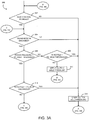
- the transmission control module 132 may be configured to execute a method 200 for enabling hill ascent/descent transmission control of the transmission 106.
- the method 200 begins with block 202 in which the transmission control module 132 determines whether to enable the hill ascent/descent transmission control feature. The enablement of the transmission control may be based on any one or more criteria such as user selection, environmental conditions, and/or other criteria. If the transmission control module 132 determines that the transmission control should not be enabled, the method 200 advances to block 210 in which the hill ascent/descent transmission control is disabled. However, if the transmission control module 132 determines that hill ascent/descent transmission control should be enable, the method 200 advances to block 204.
- the transmission control module 132 compares the transmission output speed signal received from the transmission output sensor 140 to a transmission speed threshold to determine whether the current rotational output speed of the transmission output shaft 112 is below a maximum threshold (i.e., whether the transmission 106 is initially engaged to move the vehicle 100 from a stationary or near stationary position).
- a transmission speed threshold is about 25 revolutions per minute, but other transmission speed threshold values may be used in other embodiments based on any one or more criteria such as vehicle type, vehicle mass, transmission type, locality, and/or the like. If the transmission output speed is determined to be greater than the transmission speed threshold, the method 200 advances to block 210 in which the hill ascent/descent transmission control is disabled. However, if transmission output speed is determined to be equal to or less than the transmission speed threshold, the method 200 advances to block 206.
- the transmission control module 132 compares the throttle signal received from the engine throttle sensor 142 (or from the engine control module 150) to a throttle low threshold to determine whether the vehicle 100 is stopped or otherwise at a substantially stationary position.
- the low throttle threshold is set within the range of about 2%-3% throttle displacement.
- other throttle low thresholds may be used to determine whether the vehicle 100 is stopped or near-stationary. If the throttle signal is determined to be greater than the throttle low threshold, the method 200 advances to block 210 in which the hill ascent/descent transmission control is disabled. However, if throttle signal is determined to be equal to or less than the throttle low threshold, the method 200 advances to block 208.
- the transmission control module 132 compares the brake signal received from the brake sensor 144 (or from the engine control module 150) to a brake low pressure threshold to determine whether an operator of the vehicle 100 is applying the brake (e.g., whether the operator has his/her foot on the brake).
- the brake signal is embodied as a binary state signal (i.e., brake on/off signal)
- the brake low pressure threshold may embodied as a simple on-state check.
- the brake low pressure threshold may be embodied a corresponding pressure value or percentage.
- the low brake pressure threshold is about 10 pounds per square inch (PSI).
- the vehicle 100 is fitted with an air brake system.
- the brake system of the vehicle 100 may be embodied as a hydraulic brake system or other type of brake system.
- the low brake pressure threshold, and other brake pressure thresholds discussed below may be adjusted or otherwise dependent on the type of brake system included in the vehicle 100.
- the method 200 advances to block 210 in which the hill ascent/descent transmission control is disabled. However, if brake signal is determined to be equal to or greater than the brake low pressure threshold, the method 200 advances to block 212 in which the hill ascent/descent transmission control is enabled.
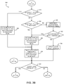
- the transmission control module 132 may execute a method 300 for controlling transmission torque of the transmission 106 of the vehicle 100 to provide hill ascent and/or descent assistance.
- the method 300 begins with block 302 in which the transmission control module 132 determines whether the hill ascent/descent control feature has been enabled.
- the transmission control module 132 may execute the method 200 to enable or disable the hill ascent/descent control feature.
- the method 300 advances to block 304 in which the transmission control module 132 determines whether the transmission 106 is engaged. That is, the transmission control module 132 determines whether the transmission 106 is in a forward gear or a reverse gear (i.e., not parked or neutral).
- the transmission control module 132 may determine whether the transmission 106 is engaged using any suitable methodology.
- the system 130 may include a shift sensor coupled to the transmission 106, a shift selector of the vehicle 100, or other component of the vehicle 100 to detect the current shift state of the transmission 106.
- the method 300 advances to block 306 in which the transmission control module 132 compares the brake signal received form the brake sensor 144 (or from the engine control module 150) to a brake high or upper brake threshold. That is, in block 306, the transmission control module 132 determines whether the operator of the vehicle has the brake fully applied (or near fully applied) or is in the process of, for example, switching his/her foot from the brake pedal to the accelerator.
- the brake signal is embodied as a binary state signal (i.e., brake on/off signal)
- the brake high pressure threshold may embodied as a simple on-state check.
- the brake high pressure threshold may be embodied a corresponding pressure value or percentage.
- the brake high pressure threshold is about 45 pounds per square inch (PSI).
- PSI pounds per square inch
- the transmission control module 132 determines that the brake signal is equal to or greater than the brake pressure high threshold, the method 300 advances to block 308.
- the transmission control module 132 compares the throttle signal received from the engine throttle sensor 142 (or from the engine control module 150) to a throttle high threshold to determine whether the operator has applied enough accelerator to overcome the roll-back or roll-forward of the vehicle 100 (i.e., whether the operator is now fully in acceleration mode).
- the throttle high threshold is equal to about 80% throttle displacement, but other throttle high threshold values may be used in other embodiments based on, for example, the type of drive unit 104 or transmission 106, the vehicle load 108, various environmental factors, and/or other criteria.
- the method 300 advances to block 310 in which a clutch hold pressure is applied to the clutch assembly 122. That is, the transmission control module 132 generates a clutch signal to engage one or more clutches of the clutch assembly 122 to apply the clutch hold pressure.
- the clutches of the clutch assembly 122 are engaged to "lock" the transmission 106 or otherwise apply an amount of transmission torque to the output shaft 112 of the transmission 106 to resist the rolling (i.e., roll-back or roll-forward) of the vehicle 100. To do so, a sufficient clutch hold pressure is selected, or otherwise determined, to hold the vehicle 100 in the current stationary or near-stationary position (i.e., resist the rolling of the vehicle 100).
- the magnitude of the initial clutch hold pressure may be preset or may be determined based on various criteria such as the type of transmission 106, the vehicle load 108, and/or other criteria. In the illustrative embodiment, the initial clutch hold pressure is equal to about 45 PSI, but clutch hold pressures of other magnitudes may be used in other embodiments. Additionally, in the illustrative embodiment, two clutches (e.g., clutches C4 and C5) of the clutch assembly 122 are engaged to "lock" the transmission 106. However, the number and selection of clutches engage in block 310 may depend on, for example, the type of transmission 106, the gearing system 120, and/or other criteria. After the clutch hold pressure is applied to the clutch assembly 122 in block 310, the method 300 loops back to block 302.
- the method 300 advances to block 314.
- any clutch hold pressure currently applied to the clutch assembly 122 based on the method 300 is dropped or otherwise released.
- the method 300 subsequently advances to block 324 (see FIG. 3B ) in which the transmission control module 132 determines whether the current clutch hold pressure is substantially zero. If so, the method 300 loops back to block 302 in which the transmission control module 132 again determines whether the hill/ascent transmission control feature is enabled. However, if the current clutch hold pressure is not substantially zero, the method 300 advances to block 304 in which the transmission control module 132 again determines whether the transmission 106 is engaged as discussed above.
- the transmission control module 132 determines that the brake signal is less than the brake pressure high threshold, the method 300 advances to block 316.
- block 316 similar to block 308, the transmission control module 132 compares the throttle signal received from the engine throttle sensor 142 (or from the engine control module 150) to the throttle high threshold to determine whether the operator has applied enough accelerator to overcome the roll-back or roll-forward of the vehicle 100. If so, the method advances to block 314 wherein the any clutch hold pressure currently applied to the clutch assembly 122 based on the method 300 is dropped or otherwise released as discussed above. If, however, transmission control module 132 determines that the throttle signal is less than the throttle high threshold in block 316, the method 300 advances to block 318 (see FIG. 3B ).
- the transmission control module 132 compares the throttle signal to a throttle medium threshold.
- the throttle medium threshold is less than the throttle high threshold and is selected so as to determine whether the operator of the vehicle 100 is in the process of applying the accelerator pedal (i.e., moving his/her foot from the brake pedal to the accelerator pedal).
- the throttle medium threshold is equal to about 60% throttle displacement.
- other throttle medium thresholds may be used in other embodiments based on the type of drive unit 104, the type of transmission 106, the type of vehicle load 108, and/or the like.
- the transmission control module 132 determines that the throttle signal is greater than the throttle medium threshold (i.e., greater than the throttle medium threshold and less than the throttle high threshold)
- the method 300 advances to block 320 in which a ramp rate to decrease the clutch hold pressure is set to a relatively high ramp rate.
- the particular value of the high ramp rate may be determined, or otherwise based on, any one or more of a number of criteria such as the current clutch hold pressure, the throttle signal, the type of transmission 106, and/or other criteria.
- the ramp rate may be expressed in any suitable format such as, for example, a percentage of pressure drop per time period, a magnitude of pressure drop per time period, and/or the like. In the illustrative embodiment, the high ramp rate is about 15 PSI per second. Of course, a high ramp rate having a different magnitude may be used in other embodiments.
- the method 300 advances to block 322 in which a new clutch hold pressure is determined based on the current clutch hold pressure and the current ramp rate.
- the transmission control module 132 multiplies the current clutch hold pressure and the current ramp rate to determine the new clutch hold pressure.
- other methods for calculating or otherwise determining the new clutch hold pressure based on the current clutch hold pressure and the current ramp rate may be used.
- a look-up table may be used.
- the ramp rate may be embodied as a reduction in pressure over time. In such embodiments, the new clutch hold pressure continues to decrease over time according to the current ramp rate.
- the method 300 advances to block 324 in which the transmission control module 132 again determines whether the clutch hold pressure is substantially zero. If so, the method 300 loops back to block 302 in which the transmission control module 132 again determines whether the hill/ascent transmission control feature is enabled. However, if the current clutch hold pressure is not substantially zero, the method 300 advances to block 304 in which the transmission control module 132 again determines whether the transmission 106 is engaged as discussed above.
- the transmission control module 132 compares the throttle signal to a throttle low threshold.
- the throttle low threshold is less than the throttle medium threshold and is selected so as to determine whether the operator of the vehicle 100 has started applying the accelerator.
- the throttle low threshold is equal to about 30% throttle displacement.
- other throttle low thresholds may be used in other embodiments based on the type of drive unit 104, the type of transmission 106, the type of vehicle load 108, and/or the like.
- the transmission control module 132 determines that the throttle signal is greater than the throttle low threshold (i.e., greater than the throttle low threshold and less than the throttle medium threshold)
- the method 300 advances to block 328 in which the ramp rate is set to a relatively low ramp rate.
- the particular value of the low ramp rate may be determined, or otherwise based on, any one or more of a number of criteria such as the current clutch hold pressure, the throttle signal, the type of transmission 106, and/or other criteria.
- the low ramp rate is about 7.5 PSI per second.
- a low ramp rate having a different magnitude may be used in other embodiments.
- the method 300 advances to block 322 in which a new clutch hold pressure is determined based on the current clutch hold pressure and the current ramp rate as discussed above. It should be appreciated that the ramp rates are used to "bleed off' or otherwise reduce the clutch hold pressure according to where the operator is in the process of switching from the brake pedal to the full accelerator. If the operators has just released the brake and is initially applying the accelerator (i.e., the throttle is less than the throttle medium threshold and greater than the throttle low threshold), the clutch hold pressure is released or decreased at a relatively slow rate.
- the clutch hold pressure is released or decreased at a relatively high rate.
- the method 300 is responsive to the state of the acceleration from the stationary position of the vehicle 100.
- a clutch hold pressure timer is incremented.
- the clutch hold pressure timer is used to ensure that the operator of the vehicle 100 has not left the vehicle 100. That is, the clutch hold pressure is held only for a reference time period when the transmission control module 132 determines that the brake pedal not fully applied (see block 306) and the throttle is less than the throttle low threshold (see block 326) so as to prevent the vehicle 100 from being held in a stationary or near stationary position while unattended.
- the method 300 advances to block 332 in which the transmission control module 132 compares the clutch hold pressure timer to a timer threshold.
- the value of the timer threshold may be selected, or otherwise determined, based on any one or more criteria such as the type of vehicle 100, the type of transmission 106, and/or other criteria.
- the timer threshold is equal to about 3.0 seconds; however, timer thresholds having other values may be used in other embodiments.
- the transmission control module 132 determines that the current clutch hold pressure timer is greater than the timer threshold, the method 300 advances to block 328 in which the ramp rate is set to the low ramp rate to begin to "bleed off' the clutch pressure as discussed above. If, however, the transmission control module 132 determines that the clutch pressure timer is not greater than the timer threshold, the method 300 advances to block 334 in which the clutch hold pressure is applied to the clutch assembly 122 or otherwise maintained. To do so, as discussed above with regard to block 310, the transmission control module 132 generates a clutch signal to engage one or more clutches of the clutch assembly 122 to apply the clutch hold pressure.
- the clutches of the clutch assembly 122 are engaged to "lock" the transmission 106 or otherwise apply an amount of transmission torque to the output shaft 112 of the transmission 106 to resist the rolling (i.e., roll-back or roll-forward) of the vehicle 100.
- the magnitude of the clutch hold pressure is selected, or otherwise determined, to hold the vehicle 100 in the current stationary or near-stationary position (i.e., resist the rolling of the vehicle 100).
- the magnitude of the initial clutch hold pressure may be preset or may be determined based on various criteria such as the type of transmission 106, the vehicle load 108, and/or other criteria. In the illustrative embodiment, the initial clutch hold pressure is equal to about 45 PSI, but clutch hold pressures of other magnitudes may be used in other embodiments.
- the method 300 advances to block 324 in which the transmission control module 132 again determines whether the clutch hold pressure is substantially zero. If so, the method 300 loops back to block 302 in which the transmission control module 132 again determines whether the hill/ascent transmission control feature is enabled. However, if the current clutch hold pressure is not substantially zero, the method 300 advances to block 304 in which the transmission control module 132 again determines whether the transmission 106 is engaged as discussed above.
- the methods 200 and 300 have been described above with regard to the illustrative FIGS. 2 and 3 in which blocks of the methods 200 and 300 are shown in an illustrative format and sequence. However, it should be appreciate that in other embodiments some of the blocks of the methods 200 and 300 may be performed contemporaneously with other blocks and/or performed in an alternative sequence. As such, the methods 200 and 300 are not limited to the particular sequence of blocks illustrated in FIGS. 2 and 3 . Additionally, it should be appreciated that the methods 200 and 300 may be executed in parallel, or otherwise contemporaneously, with each other with each other.
Landscapes
- Engineering & Computer Science (AREA)
- General Engineering & Computer Science (AREA)
- Mechanical Engineering (AREA)
- Physics & Mathematics (AREA)
- Fluid Mechanics (AREA)
- Control Of Transmission Device (AREA)
- Hydraulic Clutches, Magnetic Clutches, Fluid Clutches, And Fluid Joints (AREA)
Applications Claiming Priority (2)
| Application Number | Priority Date | Filing Date | Title |
|---|---|---|---|
| US201261611952P | 2012-03-16 | 2012-03-16 | |
| PCT/US2013/031926 WO2013138692A1 (en) | 2012-03-16 | 2013-03-15 | Device and method for controlling transmission torque to provide hill ascent and/or descent assistance |
Publications (3)
| Publication Number | Publication Date |
|---|---|
| EP2825793A1 EP2825793A1 (en) | 2015-01-21 |
| EP2825793A4 EP2825793A4 (en) | 2016-10-12 |
| EP2825793B1 true EP2825793B1 (en) | 2021-09-22 |
Family
ID=49161841
Family Applications (1)
| Application Number | Title | Priority Date | Filing Date |
|---|---|---|---|
| EP13760667.9A Active EP2825793B1 (en) | 2012-03-16 | 2013-03-15 | Device and method for controlling transmission torque to provide hill ascent and/or descent assistance |
Country Status (8)
| Country | Link |
|---|---|
| US (1) | US9964162B2 (ko) |
| EP (1) | EP2825793B1 (ko) |
| KR (1) | KR102070470B1 (ko) |
| CN (1) | CN104302955B (ko) |
| AU (1) | AU2013231924B2 (ko) |
| CA (1) | CA2867584C (ko) |
| IN (1) | IN2014DN08391A (ko) |
| WO (1) | WO2013138692A1 (ko) |
Families Citing this family (7)
| Publication number | Priority date | Publication date | Assignee | Title |
|---|---|---|---|---|
| CN103527767B (zh) * | 2013-09-24 | 2016-02-03 | 浙江吉利控股集团有限公司 | 一种自动变速器坡道爬行辅助控制方法 |
| ES2934213T3 (es) * | 2015-06-05 | 2023-02-20 | Gogoro Inc | Sistemas y métodos para detección de carga de vehículo y respuesta |
| KR101755905B1 (ko) * | 2015-11-30 | 2017-07-20 | 현대자동차주식회사 | 차량용 변속장치의 제어방법 |
| JP6995467B2 (ja) * | 2016-08-26 | 2022-01-14 | 株式会社小松製作所 | ホイールローダ、およびホイールローダの制御方法 |
| US11584372B2 (en) * | 2016-12-28 | 2023-02-21 | Baidu Usa Llc | Method to dynamically adjusting speed control rates of autonomous vehicles |
| US10830345B1 (en) * | 2019-04-16 | 2020-11-10 | Fca Us Llc | Brake-dependent clutch holding pressure while transmission is in neutral |
| US11639162B2 (en) | 2019-11-26 | 2023-05-02 | Robert Bosch Gmbh | Reducing braking torque instead of engine torque to accelerate vehicle during vehicle hill descent control |
Family Cites Families (46)
| Publication number | Priority date | Publication date | Assignee | Title |
|---|---|---|---|---|
| US4644826A (en) | 1984-08-24 | 1987-02-24 | Toyota Jidosha Kabushiki Kaisha | Idling control system for an automatic transmission providing smooth starting off action |
| JPS62261551A (ja) * | 1986-05-08 | 1987-11-13 | Komatsu Ltd | 自動変速装置における発進速度段選択装置 |
| US4757886A (en) * | 1987-01-20 | 1988-07-19 | Ford Motor Company | Transmission clutch closed loop slip controller and method |
| US5046174A (en) * | 1990-01-11 | 1991-09-03 | General Motors Corporation | Method of clutch-to-clutch closed throttle downshift in an automatic transmission |
| US5029494A (en) * | 1989-12-26 | 1991-07-09 | General Motors Corporation | Control method of clutch-to-clutch powered downshift in an automatic transmission |
| US5040648A (en) * | 1990-11-05 | 1991-08-20 | Caterpillar Inc. | Electrohydraulic control device for a drive train of a vehicle |
| US5137127A (en) | 1991-04-03 | 1992-08-11 | Eaton Corporation | Motor vehicle hill holder system |
| US5305663A (en) * | 1992-08-10 | 1994-04-26 | Ford Motor Company | Automatic transmission control system |
| US5343782A (en) * | 1992-08-31 | 1994-09-06 | General Motors Corporation | Anti-flare method using offgoing slip speed and rate of change of slip-speed to determine pressure compensation for incoming clutch |
| ES2105618T3 (es) | 1992-12-18 | 1997-10-16 | Procter & Gamble | Aparato y metodo de apilamiento que reorientan unidades de productos a lo largo de una curva generalmente helicoidal al tiempo que son transportados desde una estacion de carga a una estacion de descarga. |
| US5456333A (en) * | 1993-03-25 | 1995-10-10 | Caterpillar Inc. | Electrohydraulic control device for a drive train of a vehicle |
| JPH0719337A (ja) * | 1993-06-30 | 1995-01-20 | Daihatsu Motor Co Ltd | 自動変速機のクリープトルク制御装置 |
| US5417621A (en) * | 1993-12-22 | 1995-05-23 | Ford Motor Company | Driveaway lockup strategy for an infinitely variable tranmission with a hydrokinetic torque converter |
| JP2878964B2 (ja) | 1994-05-02 | 1999-04-05 | アイシン・エィ・ダブリュ株式会社 | 自動変速機の制御方法及び制御装置 |
| US5474164A (en) * | 1994-05-09 | 1995-12-12 | Ford Motor Company | Vehicle transmission hill holder |
| JP2828606B2 (ja) | 1995-05-12 | 1998-11-25 | アイシン・エィ・ダブリュ株式会社 | 自動変速機の制御装置 |
| JP2876112B2 (ja) | 1995-06-30 | 1999-03-31 | アイシン・エィ・ダブリュ株式会社 | 自動変速機の制御装置 |
| JP3301296B2 (ja) * | 1995-12-28 | 2002-07-15 | アイシン・エィ・ダブリュ株式会社 | 自動変速機の制御装置 |
| US5693878A (en) * | 1997-01-23 | 1997-12-02 | Ford Global Technologies, Inc. | Torque converter clutch engagement test |
| FR2784639B1 (fr) * | 1998-10-14 | 2006-09-08 | Luk Getriebe Systeme Gmbh | Dispositif et procede de verrouillage en pente pour vehicule automobile |
| GB2349926B (en) * | 1999-04-15 | 2003-08-06 | Komatsu Mfg Co Ltd | Shift control apparatus of working vehicle |
| US6319172B1 (en) * | 2000-03-14 | 2001-11-20 | General Motors Corporation | Off-going clutch control for upshifting of an automatic transmission |
| US6308125B1 (en) * | 2000-05-11 | 2001-10-23 | General Motors Corporation | Adaptive clutch control of a closed-throttle downshift |
| JP2002256921A (ja) | 2001-02-28 | 2002-09-11 | Toyota Motor Corp | 車両の制御装置 |
| GB0119263D0 (en) * | 2001-08-08 | 2001-10-03 | Ford Global Tech Inc | A vehicle speed control system |
| US6656087B1 (en) * | 2002-06-11 | 2003-12-02 | General Motors Corporation | Multi-stage skip downshift control for an automatic transmission |
| US6684148B2 (en) | 2002-06-12 | 2004-01-27 | Nacco Materials Handling Group, Inc. | Transmission control system |
| US7974760B2 (en) * | 2003-10-20 | 2011-07-05 | Nmhg Oregon, Inc. | Advanced power-shift transmission control system |
| DE10320775A1 (de) * | 2003-05-09 | 2004-12-02 | Zf Friedrichshafen Ag | Verfahren zum Steuern eines Automatgetriebes mit einer Anfahrkupplung und mehreren Schaltelementen |
| JP4089571B2 (ja) | 2003-09-24 | 2008-05-28 | トヨタ自動車株式会社 | 自動変速機の制御装置 |
| US7136735B2 (en) | 2003-10-02 | 2006-11-14 | General Motors Corporation | Adaptive hill hold for automobile applications by redundant clutch apply |
| US7166060B2 (en) | 2005-01-18 | 2007-01-23 | Ford Global Technologies, Llc. | Hill hold for a vehicle |
| US7590480B2 (en) * | 2005-07-05 | 2009-09-15 | Gm Global Technology Operations, Inc. | Adaptive shift learn control for automatic transmissions |
| US7912615B2 (en) | 2005-12-09 | 2011-03-22 | Volvo Lastvagnar Ab | Method for gear selection during driving of a vehicle in a heavy uphill drive condition |
| US7509202B2 (en) * | 2006-01-17 | 2009-03-24 | General Motors Corporation | Neutral idle hill detection |
| DE102007023957A1 (de) | 2007-05-23 | 2008-11-27 | Zf Friedrichshafen Ag | Verfahren zur Steuerung eines automatisierten Lastschaltgetriebes |
| US8825320B2 (en) * | 2007-11-02 | 2014-09-02 | GM Global Technology Operations LLC | Method and apparatus for developing a deceleration-based synchronous shift schedule |
| DE102008043104A1 (de) * | 2008-10-23 | 2010-04-29 | Zf Friedrichshafen Ag | Verfahren zum Betätigen einer Kupplung eines hydrodynamischen Drehmomentwandlers |
| DE102008043560A1 (de) | 2008-11-07 | 2010-05-12 | Zf Friedrichshafen Ag | Verfahren zur Steuerung eines automatisierten Stufenschaltgetriebes |
| US8694218B2 (en) | 2009-03-24 | 2014-04-08 | Allison Transmission, Inc. | Acceleration based mode switch |
| US8332108B2 (en) | 2009-06-01 | 2012-12-11 | Allison Transmission, Inc. | System for determining a vehicle mass-based breakpoint for selecting between two different transmission shift schedules |
| DE102009046340A1 (de) | 2009-11-03 | 2011-05-05 | Zf Friedrichshafen Ag | Verfahren zur Steuerung einer Roll- oder Segelfunktion eines Fahrzeugs |
| JP2011179597A (ja) * | 2010-03-01 | 2011-09-15 | Denso Corp | 車両駆動システムの制御装置 |
| US8328687B2 (en) * | 2010-07-09 | 2012-12-11 | Ford Global Technologies, Llc | Method for controlling an engine that may be automatically stopped |
| US8414456B2 (en) * | 2010-07-09 | 2013-04-09 | Ford Global Technologies, Llc | Method for starting an engine |
| US20110166756A1 (en) | 2011-02-01 | 2011-07-07 | Essam Tawfik Marcus | Anti-rollback Control System for Hybrid and Conventional Powertrain Vehicles |
-
2013
- 2013-03-15 IN IN8391DEN2014 patent/IN2014DN08391A/en unknown
- 2013-03-15 AU AU2013231924A patent/AU2013231924B2/en active Active
- 2013-03-15 CN CN201380025547.0A patent/CN104302955B/zh active Active
- 2013-03-15 WO PCT/US2013/031926 patent/WO2013138692A1/en active Application Filing
- 2013-03-15 EP EP13760667.9A patent/EP2825793B1/en active Active
- 2013-03-15 KR KR1020147028847A patent/KR102070470B1/ko active IP Right Grant
- 2013-03-15 CA CA2867584A patent/CA2867584C/en active Active
- 2013-03-15 US US13/835,265 patent/US9964162B2/en active Active
Also Published As
| Publication number | Publication date |
|---|---|
| AU2013231924A1 (en) | 2014-10-02 |
| KR102070470B1 (ko) | 2020-01-29 |
| CA2867584C (en) | 2020-04-21 |
| EP2825793A4 (en) | 2016-10-12 |
| CN104302955B (zh) | 2016-11-09 |
| IN2014DN08391A (ko) | 2015-05-08 |
| CN104302955A (zh) | 2015-01-21 |
| AU2013231924B2 (en) | 2017-04-20 |
| WO2013138692A1 (en) | 2013-09-19 |
| KR20140136994A (ko) | 2014-12-01 |
| EP2825793A1 (en) | 2015-01-21 |
| US9964162B2 (en) | 2018-05-08 |
| US20130304339A1 (en) | 2013-11-14 |
| CA2867584A1 (en) | 2013-09-19 |
Similar Documents
| Publication | Publication Date | Title |
|---|---|---|
| EP2825409B1 (en) | Device for controlling transmission torque to provide hill ascent and/or descent assistance | |
| EP2825793B1 (en) | Device and method for controlling transmission torque to provide hill ascent and/or descent assistance | |
| US7160225B2 (en) | Method, device and use thereof for operating a motor vehicle | |
| EP3004694B1 (en) | Interactive transmission shift techniques | |
| US10295054B2 (en) | Method and control for operating transmission during clutch failure when shifting from gear to neutral | |
| US10647323B2 (en) | Method for operating a motor vehicle by creep mode of the clutch | |
| US20140121914A1 (en) | Acceleration-based state control of a binary clutch assembly | |
| US10393256B2 (en) | Control device for vehicle drive apparatus | |
| US11040718B2 (en) | Launch control method for a vehicle | |
| CN104417534A (zh) | 一种限制离合器接合过程中摩擦离合器能量耗散量的方法 | |
| CN109237014B (zh) | 一种湿式双离合器自动变速器的控制方法及系统 | |
| EP3204274B1 (en) | A method to control a powertrain in a vehicle | |
| CN115289210A (zh) | 用于自动变速器的低扭矩升挡的转换控制 | |
| US20190011043A1 (en) | Transmission device |
Legal Events
| Date | Code | Title | Description |
|---|---|---|---|
| PUAI | Public reference made under article 153(3) epc to a published international application that has entered the european phase |
Free format text: ORIGINAL CODE: 0009012 |
|
| STAA | Information on the status of an ep patent application or granted ep patent |
Free format text: STATUS: REQUEST FOR EXAMINATION WAS MADE |
|
| 17P | Request for examination filed |
Effective date: 20140916 |
|
| AK | Designated contracting states |
Kind code of ref document: A1 Designated state(s): AL AT BE BG CH CY CZ DE DK EE ES FI FR GB GR HR HU IE IS IT LI LT LU LV MC MK MT NL NO PL PT RO RS SE SI SK SM TR |
|
| AX | Request for extension of the european patent |
Extension state: BA ME |
|
| DAX | Request for extension of the european patent (deleted) | ||
| RA4 | Supplementary search report drawn up and despatched (corrected) |
Effective date: 20160908 |
|
| RIC1 | Information provided on ipc code assigned before grant |
Ipc: F16H 61/20 20060101AFI20160902BHEP |
|
| REG | Reference to a national code |
Ref country code: DE Ref legal event code: R079 Ref document number: 602013079365 Country of ref document: DE Free format text: PREVIOUS MAIN CLASS: F16H0059660000 Ipc: F16H0061200000 |
|
| GRAP | Despatch of communication of intention to grant a patent |
Free format text: ORIGINAL CODE: EPIDOSNIGR1 |
|
| STAA | Information on the status of an ep patent application or granted ep patent |
Free format text: STATUS: GRANT OF PATENT IS INTENDED |
|
| RIC1 | Information provided on ipc code assigned before grant |
Ipc: F16H 61/00 20060101ALI20210420BHEP Ipc: F16H 61/20 20060101AFI20210420BHEP |
|
| INTG | Intention to grant announced |
Effective date: 20210512 |
|
| GRAS | Grant fee paid |
Free format text: ORIGINAL CODE: EPIDOSNIGR3 |
|
| GRAA | (expected) grant |
Free format text: ORIGINAL CODE: 0009210 |
|
| STAA | Information on the status of an ep patent application or granted ep patent |
Free format text: STATUS: THE PATENT HAS BEEN GRANTED |
|
| AK | Designated contracting states |
Kind code of ref document: B1 Designated state(s): AL AT BE BG CH CY CZ DE DK EE ES FI FR GB GR HR HU IE IS IT LI LT LU LV MC MK MT NL NO PL PT RO RS SE SI SK SM TR |
|
| REG | Reference to a national code |
Ref country code: GB Ref legal event code: FG4D |
|
| REG | Reference to a national code |
Ref country code: IE Ref legal event code: FG4D |
|
| REG | Reference to a national code |
Ref country code: DE Ref legal event code: R096 Ref document number: 602013079365 Country of ref document: DE |
|
| REG | Reference to a national code |
Ref country code: CH Ref legal event code: EP Ref country code: AT Ref legal event code: REF Ref document number: 1432583 Country of ref document: AT Kind code of ref document: T Effective date: 20211015 |
|
| REG | Reference to a national code |
Ref country code: LT Ref legal event code: MG9D |
|
| REG | Reference to a national code |
Ref country code: NL Ref legal event code: MP Effective date: 20210922 |
|
| PG25 | Lapsed in a contracting state [announced via postgrant information from national office to epo] |
Ref country code: HR Free format text: LAPSE BECAUSE OF FAILURE TO SUBMIT A TRANSLATION OF THE DESCRIPTION OR TO PAY THE FEE WITHIN THE PRESCRIBED TIME-LIMIT Effective date: 20210922 Ref country code: SE Free format text: LAPSE BECAUSE OF FAILURE TO SUBMIT A TRANSLATION OF THE DESCRIPTION OR TO PAY THE FEE WITHIN THE PRESCRIBED TIME-LIMIT Effective date: 20210922 Ref country code: FI Free format text: LAPSE BECAUSE OF FAILURE TO SUBMIT A TRANSLATION OF THE DESCRIPTION OR TO PAY THE FEE WITHIN THE PRESCRIBED TIME-LIMIT Effective date: 20210922 Ref country code: RS Free format text: LAPSE BECAUSE OF FAILURE TO SUBMIT A TRANSLATION OF THE DESCRIPTION OR TO PAY THE FEE WITHIN THE PRESCRIBED TIME-LIMIT Effective date: 20210922 Ref country code: NO Free format text: LAPSE BECAUSE OF FAILURE TO SUBMIT A TRANSLATION OF THE DESCRIPTION OR TO PAY THE FEE WITHIN THE PRESCRIBED TIME-LIMIT Effective date: 20211222 Ref country code: BG Free format text: LAPSE BECAUSE OF FAILURE TO SUBMIT A TRANSLATION OF THE DESCRIPTION OR TO PAY THE FEE WITHIN THE PRESCRIBED TIME-LIMIT Effective date: 20211222 Ref country code: LT Free format text: LAPSE BECAUSE OF FAILURE TO SUBMIT A TRANSLATION OF THE DESCRIPTION OR TO PAY THE FEE WITHIN THE PRESCRIBED TIME-LIMIT Effective date: 20210922 |
|
| REG | Reference to a national code |
Ref country code: AT Ref legal event code: MK05 Ref document number: 1432583 Country of ref document: AT Kind code of ref document: T Effective date: 20210922 |
|
| PG25 | Lapsed in a contracting state [announced via postgrant information from national office to epo] |
Ref country code: LV Free format text: LAPSE BECAUSE OF FAILURE TO SUBMIT A TRANSLATION OF THE DESCRIPTION OR TO PAY THE FEE WITHIN THE PRESCRIBED TIME-LIMIT Effective date: 20210922 Ref country code: GR Free format text: LAPSE BECAUSE OF FAILURE TO SUBMIT A TRANSLATION OF THE DESCRIPTION OR TO PAY THE FEE WITHIN THE PRESCRIBED TIME-LIMIT Effective date: 20211223 |
|
| PG25 | Lapsed in a contracting state [announced via postgrant information from national office to epo] |
Ref country code: AT Free format text: LAPSE BECAUSE OF FAILURE TO SUBMIT A TRANSLATION OF THE DESCRIPTION OR TO PAY THE FEE WITHIN THE PRESCRIBED TIME-LIMIT Effective date: 20210922 |
|
| PG25 | Lapsed in a contracting state [announced via postgrant information from national office to epo] |
Ref country code: IS Free format text: LAPSE BECAUSE OF FAILURE TO SUBMIT A TRANSLATION OF THE DESCRIPTION OR TO PAY THE FEE WITHIN THE PRESCRIBED TIME-LIMIT Effective date: 20220122 Ref country code: SK Free format text: LAPSE BECAUSE OF FAILURE TO SUBMIT A TRANSLATION OF THE DESCRIPTION OR TO PAY THE FEE WITHIN THE PRESCRIBED TIME-LIMIT Effective date: 20210922 Ref country code: RO Free format text: LAPSE BECAUSE OF FAILURE TO SUBMIT A TRANSLATION OF THE DESCRIPTION OR TO PAY THE FEE WITHIN THE PRESCRIBED TIME-LIMIT Effective date: 20210922 Ref country code: PT Free format text: LAPSE BECAUSE OF FAILURE TO SUBMIT A TRANSLATION OF THE DESCRIPTION OR TO PAY THE FEE WITHIN THE PRESCRIBED TIME-LIMIT Effective date: 20220124 Ref country code: PL Free format text: LAPSE BECAUSE OF FAILURE TO SUBMIT A TRANSLATION OF THE DESCRIPTION OR TO PAY THE FEE WITHIN THE PRESCRIBED TIME-LIMIT Effective date: 20210922 Ref country code: NL Free format text: LAPSE BECAUSE OF FAILURE TO SUBMIT A TRANSLATION OF THE DESCRIPTION OR TO PAY THE FEE WITHIN THE PRESCRIBED TIME-LIMIT Effective date: 20210922 Ref country code: ES Free format text: LAPSE BECAUSE OF FAILURE TO SUBMIT A TRANSLATION OF THE DESCRIPTION OR TO PAY THE FEE WITHIN THE PRESCRIBED TIME-LIMIT Effective date: 20210922 Ref country code: EE Free format text: LAPSE BECAUSE OF FAILURE TO SUBMIT A TRANSLATION OF THE DESCRIPTION OR TO PAY THE FEE WITHIN THE PRESCRIBED TIME-LIMIT Effective date: 20210922 Ref country code: CZ Free format text: LAPSE BECAUSE OF FAILURE TO SUBMIT A TRANSLATION OF THE DESCRIPTION OR TO PAY THE FEE WITHIN THE PRESCRIBED TIME-LIMIT Effective date: 20210922 Ref country code: AL Free format text: LAPSE BECAUSE OF FAILURE TO SUBMIT A TRANSLATION OF THE DESCRIPTION OR TO PAY THE FEE WITHIN THE PRESCRIBED TIME-LIMIT Effective date: 20210922 |
|
| REG | Reference to a national code |
Ref country code: DE Ref legal event code: R097 Ref document number: 602013079365 Country of ref document: DE |
|
| PG25 | Lapsed in a contracting state [announced via postgrant information from national office to epo] |
Ref country code: DK Free format text: LAPSE BECAUSE OF FAILURE TO SUBMIT A TRANSLATION OF THE DESCRIPTION OR TO PAY THE FEE WITHIN THE PRESCRIBED TIME-LIMIT Effective date: 20210922 |
|
| PLBE | No opposition filed within time limit |
Free format text: ORIGINAL CODE: 0009261 |
|
| STAA | Information on the status of an ep patent application or granted ep patent |
Free format text: STATUS: NO OPPOSITION FILED WITHIN TIME LIMIT |
|
| 26N | No opposition filed |
Effective date: 20220623 |
|
| PG25 | Lapsed in a contracting state [announced via postgrant information from national office to epo] |
Ref country code: MC Free format text: LAPSE BECAUSE OF FAILURE TO SUBMIT A TRANSLATION OF THE DESCRIPTION OR TO PAY THE FEE WITHIN THE PRESCRIBED TIME-LIMIT Effective date: 20210922 |
|
| REG | Reference to a national code |
Ref country code: CH Ref legal event code: PL |
|
| GBPC | Gb: european patent ceased through non-payment of renewal fee |
Effective date: 20220315 |
|
| PG25 | Lapsed in a contracting state [announced via postgrant information from national office to epo] |
Ref country code: SI Free format text: LAPSE BECAUSE OF FAILURE TO SUBMIT A TRANSLATION OF THE DESCRIPTION OR TO PAY THE FEE WITHIN THE PRESCRIBED TIME-LIMIT Effective date: 20210922 |
|
| REG | Reference to a national code |
Ref country code: BE Ref legal event code: MM Effective date: 20220331 |
|
| PG25 | Lapsed in a contracting state [announced via postgrant information from national office to epo] |
Ref country code: LU Free format text: LAPSE BECAUSE OF NON-PAYMENT OF DUE FEES Effective date: 20220315 Ref country code: LI Free format text: LAPSE BECAUSE OF NON-PAYMENT OF DUE FEES Effective date: 20220331 Ref country code: IT Free format text: LAPSE BECAUSE OF FAILURE TO SUBMIT A TRANSLATION OF THE DESCRIPTION OR TO PAY THE FEE WITHIN THE PRESCRIBED TIME-LIMIT Effective date: 20210922 Ref country code: IE Free format text: LAPSE BECAUSE OF NON-PAYMENT OF DUE FEES Effective date: 20220315 Ref country code: GB Free format text: LAPSE BECAUSE OF NON-PAYMENT OF DUE FEES Effective date: 20220315 Ref country code: FR Free format text: LAPSE BECAUSE OF NON-PAYMENT OF DUE FEES Effective date: 20220331 Ref country code: CH Free format text: LAPSE BECAUSE OF NON-PAYMENT OF DUE FEES Effective date: 20220331 |
|
| PG25 | Lapsed in a contracting state [announced via postgrant information from national office to epo] |
Ref country code: BE Free format text: LAPSE BECAUSE OF NON-PAYMENT OF DUE FEES Effective date: 20220331 |
|
| P01 | Opt-out of the competence of the unified patent court (upc) registered |
Effective date: 20230526 |
|
| PG25 | Lapsed in a contracting state [announced via postgrant information from national office to epo] |
Ref country code: HU Free format text: LAPSE BECAUSE OF FAILURE TO SUBMIT A TRANSLATION OF THE DESCRIPTION OR TO PAY THE FEE WITHIN THE PRESCRIBED TIME-LIMIT; INVALID AB INITIO Effective date: 20130315 |
|
| PG25 | Lapsed in a contracting state [announced via postgrant information from national office to epo] |
Ref country code: SM Free format text: LAPSE BECAUSE OF FAILURE TO SUBMIT A TRANSLATION OF THE DESCRIPTION OR TO PAY THE FEE WITHIN THE PRESCRIBED TIME-LIMIT Effective date: 20210922 Ref country code: MK Free format text: LAPSE BECAUSE OF FAILURE TO SUBMIT A TRANSLATION OF THE DESCRIPTION OR TO PAY THE FEE WITHIN THE PRESCRIBED TIME-LIMIT Effective date: 20210922 Ref country code: CY Free format text: LAPSE BECAUSE OF FAILURE TO SUBMIT A TRANSLATION OF THE DESCRIPTION OR TO PAY THE FEE WITHIN THE PRESCRIBED TIME-LIMIT Effective date: 20210922 |
|
| PGFP | Annual fee paid to national office [announced via postgrant information from national office to epo] |
Ref country code: DE Payment date: 20240327 Year of fee payment: 12 |