EP2825351B1 - An abrasive jet system - Google Patents
An abrasive jet system Download PDFInfo
- Publication number
- EP2825351B1 EP2825351B1 EP13707641.0A EP13707641A EP2825351B1 EP 2825351 B1 EP2825351 B1 EP 2825351B1 EP 13707641 A EP13707641 A EP 13707641A EP 2825351 B1 EP2825351 B1 EP 2825351B1
- Authority
- EP
- European Patent Office
- Prior art keywords
- abrasive
- suspension
- source
- cutting head
- pressure
- Prior art date
- Legal status (The legal status is an assumption and is not a legal conclusion. Google has not performed a legal analysis and makes no representation as to the accuracy of the status listed.)
- Active
Links
Images


Classifications
-
- B—PERFORMING OPERATIONS; TRANSPORTING
- B24—GRINDING; POLISHING
- B24C—ABRASIVE OR RELATED BLASTING WITH PARTICULATE MATERIAL
- B24C7/00—Equipment for feeding abrasive material; Controlling the flowability, constitution, or other physical characteristics of abrasive blasts
- B24C7/0007—Equipment for feeding abrasive material; Controlling the flowability, constitution, or other physical characteristics of abrasive blasts the abrasive material being fed in a liquid carrier
- B24C7/0015—Equipment for feeding abrasive material; Controlling the flowability, constitution, or other physical characteristics of abrasive blasts the abrasive material being fed in a liquid carrier with control of feed parameters, e.g. feed rate of abrasive material or carrier
-
- B—PERFORMING OPERATIONS; TRANSPORTING
- B24—GRINDING; POLISHING
- B24C—ABRASIVE OR RELATED BLASTING WITH PARTICULATE MATERIAL
- B24C1/00—Methods for use of abrasive blasting for producing particular effects; Use of auxiliary equipment in connection with such methods
- B24C1/04—Methods for use of abrasive blasting for producing particular effects; Use of auxiliary equipment in connection with such methods for treating only selected parts of a surface, e.g. for carving stone or glass
- B24C1/045—Methods for use of abrasive blasting for producing particular effects; Use of auxiliary equipment in connection with such methods for treating only selected parts of a surface, e.g. for carving stone or glass for cutting
-
- B—PERFORMING OPERATIONS; TRANSPORTING
- B24—GRINDING; POLISHING
- B24C—ABRASIVE OR RELATED BLASTING WITH PARTICULATE MATERIAL
- B24C3/00—Abrasive blasting machines or devices; Plants
-
- B—PERFORMING OPERATIONS; TRANSPORTING
- B24—GRINDING; POLISHING
- B24C—ABRASIVE OR RELATED BLASTING WITH PARTICULATE MATERIAL
- B24C7/00—Equipment for feeding abrasive material; Controlling the flowability, constitution, or other physical characteristics of abrasive blasts
- B24C7/0007—Equipment for feeding abrasive material; Controlling the flowability, constitution, or other physical characteristics of abrasive blasts the abrasive material being fed in a liquid carrier
- B24C7/0015—Equipment for feeding abrasive material; Controlling the flowability, constitution, or other physical characteristics of abrasive blasts the abrasive material being fed in a liquid carrier with control of feed parameters, e.g. feed rate of abrasive material or carrier
- B24C7/0023—Equipment for feeding abrasive material; Controlling the flowability, constitution, or other physical characteristics of abrasive blasts the abrasive material being fed in a liquid carrier with control of feed parameters, e.g. feed rate of abrasive material or carrier of feed pressure
-
- B—PERFORMING OPERATIONS; TRANSPORTING
- B24—GRINDING; POLISHING
- B24C—ABRASIVE OR RELATED BLASTING WITH PARTICULATE MATERIAL
- B24C7/00—Equipment for feeding abrasive material; Controlling the flowability, constitution, or other physical characteristics of abrasive blasts
- B24C7/0007—Equipment for feeding abrasive material; Controlling the flowability, constitution, or other physical characteristics of abrasive blasts the abrasive material being fed in a liquid carrier
- B24C7/003—Equipment for feeding abrasive material; Controlling the flowability, constitution, or other physical characteristics of abrasive blasts the abrasive material being fed in a liquid carrier with means for preventing clogging of the equipment
Definitions
- This invention relates to systems that feed abrasive particles suspended in water to cutting heads of abrasive waterjet apparatus.
- Ultrahigh pressure water is converted into a high velocity waterjet within a cutting head of an entrainment abrasive waterjet apparatus.
- the waterjet traverses a chamber within the cutting head that has a passaged connection through which abrasive particles in a carrier fluid enter the chamber.
- the waterjet passes out the chamber entering a contracting inlet and bore of a focus tube entraining abrasive particles and carrier fluid into the focus tube bore.
- momentum is exchanged between the waterjet and abrasive particles to generate an abrasive cutting jet at a focus tube outlet.
- Focus tubes are also known in the art as mixing tubes, abrasive waterjet nozzles and nozzles.
- Cutting jets with diameters above 200 microns require abrasive particles with mean diameters greater than 40 microns or so to cut effectively. Such particles are free flowing, easy to meter and to transport dynamically by airflow in tubing to a cutting head.
- Generating cutting jets with diameters less than 200 microns requires abrasive particles with diameters less than 40 microns or so, with particle diameters dropping to 10 microns or so for a 50 micron diameter cutting jet.
- abrasive particle diameters diminish below 40 microns inter-particle forces and friction between particles increase rapidly so that particles flow less readily and particle clumping becomes a serious problem because of rapid moisture absorption by fine abrasive exposed to the environment.
- particles less than 40 microns or so in diameter tend to attach to tube walls and cutting head passage walls as a result of electrostatic forces. Particles attached to cutting head passage walls can be wetted, particularly during the starting and stopping of water flow and this can lead to clumping of particles followed by blockage. These factors make it difficult or impossible to meter and feed abrasive particles less than 40 microns mean diameter or so from a hopper to a cutting head by dynamically suspending abrasive particles in airflow.
- the transport method of this patent application involves temporarily suspending abrasive particles in sufficient water or other liquid to flow to a cutting head. Since water is the preferred liquid this is referred to thought out the text. Abrasive particles that are temporarily suspended in water are referred to as abrasive suspension thought out the text.
- abrasive in the text is taken to mean abrasive particles.
- Cutting heads that entrain abrasive suspension have been known in the art for over 30 years but have not been exploited commercially for precision machining. Reasons for this include poor cutting performance, relative to cutting heads that entrain abrasive in airflow, and complex, unreliable and difficult to operate abrasive suspension feed systems.
- Prior art such as described in US 4,872,293 , demonstrates that fine abrasive suspensions can be fed to cutting heads but do not teach how to design abrasive feed systems that make machining with abrasive suspensions commercially practical.
- Prior art does not address a number of aspects of the design and operation of abrasive suspension feed systems that must be satisfied when abrasive waterjet apparatus is part of a machine tool. These aspects include avoiding particle jamming followed by flow passage blockage, avoiding settling of abrasive suspensions during machining cycles, control over abrasive concentration in abrasive cutting jets and the automation and integration of an abrasive suspension feed system with a machine tool. All of these aspects are addressed by the present invention.
- Blockages are most likely at flow restrictions, regions of settled abrasive in tubing and flow passages and when de-watering occurs due to water wicking or migration.
- the accepted practice in the design of solid/liquid flow systems is to avoid steeply sloping conduits in order to minimise movement of solids when flow is stopped.
- abrasive particles tend to settle to form a series of plugs with essentially clear water in between. Because particles only settle over a distance of a few tube diameters blockages form quickly in steeply sloping tubing.
- Prior art is silent about the problems of abrasive settling in steeply sloping small bore tubing.
- Steeply sloping small bore conduits are unavoidable in feeding abrasive suspension to a cutting head of an abrasive waterjet apparatus so the abrasive suspension feed systems described in this patent application are designed and their operation automated to prevent problems caused by abrasive settling in steeply sloping tubing.
- An object of the invention is to alleviate the above and other drawbacks of the prior art. This is achieved by an abrasive jet system according to claim 1.
- the dependent claims refer to preferred embodiments of the invention.
- the present invention is based on the realisation that by controlling the pressure at a source of abrasive suspension conduits and tubes in an abrasive jet system may be efficiently kept free from clogging.
- the inventor has realised that by providing a displacement fluid at or near the cutting head, and controlling the pressure at said source of abrasive suspension to be below the pressure at the provided displacement fluid, a flushing/cleaning flow towards the source of abrasive suspension may be created.
- an abrasive jet system for producing an abrasive cutting jet comprising
- the source of abrasive suspension may be located in a hopper containing a suspended abrasive bed, such as at an inlet to a conduit.
- the source of abrasive suspension may be located at a point outside such a hopper, such as in a flow circuit for circulating water from/to the hopper.
- the pressure at the source of abrasive suspension may be controlled in various alternative ways.
- the pressure may be controlled by control means connected to a pump, a variable restriction and/or a vacuum source.
- said pressure at said source of abrasive suspension is a subatmospheric pressure.
- the pressure at the source of displacement fluid may be at atmospheric pressure.
- the source of abrasive suspension is at atmospheric pressure, than the pressure at the source of displacement fluid must be higher than atmospheric pressure.
- the abrasive jet system comprises a control system for controlling the opening and closing of said abrasive suspension on/off valve, wherein when said abrasive suspension on/off valve is closed, and the cutting head is void of high velocity waterjet, the control system is adapted to, within a predetermined time period, open said abrasive suspension on/off valve to allow displacement fluid to displace abrasive suspension present in the conduit towards said source of abrasive suspension.
- the control system may suitably control an actuator which is operatively connected to the valve for opening/closing the valve.
- control system may be adapted to also control the opening and closing of the valve at said source of displacement fluid.
- the clearance of abrasive from the conduit may be automated.
- the abrasive jet system comprises
- the flow in said flow circuit is greater than the flow in said conduit to the cutting head, such as more than 2 times greater, for instance 5 times greater.
- the abrasive jet system comprises
- the abrasive jet system comprises a pump in the flow circuit downstream of said junction point, wherein the pressure at the junction point is controlled by controlling the flow through the pump.
- the pump is located between said junction point and the outlet end of the flow circuit.
- said control unit is operatively connected to the pump and adapted to control the speed of/flow through the pump based on said signal from the pressure sensing device, thereby controlling the pressure at said junction point.
- the abrasive jet system comprises a variable restriction in the flow circuit upstream of said junction point, wherein the pressure at the junction point is controlled by controlling the flow through the restriction.
- the variable restriction is located between the inlet end of the flow circuit and said junction point.
- said control unit is operatively connected to the variable restriction and adapted to vary the restriction based on said signal from the pressure sensing device, thereby controlling the pressure at said junction point.
- the abrasive jet system comprises
- said hopper includes cover water above the bed of abrasive particles, the abrasive jet system further comprising
- the inlet end of the flow circuit is positioned at or positionable to a location in the agitated bed of abrasive particles where the abrasive concentration is that required at the cutting head.
- said hopper is mounted on a weight sensor for determining the amount of abrasive in said hopper.
- said agitator is movable between said bed of abrasive particles and said cover water. It should be understood that movement of the agitator between the bed and the cover water should be regarded as a relative displacement.
- the agitator may be lowered and raised, while the hopper is kept still. Reversely, in other embodiments the hopper may be raised and lowered.
- said inlet end of the flow circuit is movable between said bed of abrasive particles and said cover water.
- this is to be regarded as a relative displacement between the inlet end and the hopper.
- the outlet end may be movable relative to the hopper so that its position may be changed between said bed of abrasive particles and said cover water.
- a source of dry abrasive particles is provided above the surface of the cover water.
- the source may, for instance, be in the form of a silo.
- said control system is operatively connected to the weight sensor and the source of dry abrasive particles in order to control the discharging of dry abrasive particles from said source of dry abrasive particles onto the surface of the cover water based on an input signal from the weight sensor.
- Solid/liquid flow systems are usually designed and operated such that solids are flushed from a system before flow is stopped.
- the flow of abrasive suspension to a cutting head may be stopped and restarted over time periods ranging from a fraction of a second to sufficient time for abrasive settling to occur that would lead to a blockage on re-commencement of flow.
- abrasive suspension feed systems are designed and control systems provided such that abrasive suspension is generally available for entrainment at a cutting head but is flushed out of parts of a feed system if cutting will not, or does not occur, within a set time period. This time period can be less than a minute.
- Prior art does not consider or reveal how to design abrasive feed systems that feed cutting heads of abrasive waterjet apparatus that forms part of a machine tool that experiences dynamic cutting cycles interposed with variable periods of inactivity.
- Flow passage dimensions close to and within a cutting head are restricted and are the locations of highest risk for blockage formation.
- An event upstream of a cutting head that generates a slug of abrasive suspension with a higher than desired abrasive concentration can to lead to a blockage when the abrasive rich suspension reaches a cutting head.
- close control is maintained over abrasive suspension rheological properties and concentration at the source point of abrasive suspension and whilst it is flowing to a cutting head.
- pressure fluctuation enhances water migration in fine abrasive suspensions making de-watering particularly problematic when fluctuations are present, such as from a pump or from multiple short cutting cycles when drilling holes in thin material.
- Dewatering phenomena are caused by dilatancy of high abrasive concentration suspensions with water preferentially migrating through a suspension towards a region of lower pressure. Implementations of this invention minimise problems caused by dilatancy phenomena.
- Regions of re-circulating flow occur in cavities in passages, such as at a junction between conduits when there is no flow in one of the junction legs.
- the inventor has found that fine abrasive particles accumulate in cavities at flow junctions and de-water at a rate that is markedly influence by pressure fluctuations.
- an abrasive rich plug can form that completely fills a non-flowing junction leg and continues to grow to extend five or more passage diameters into a non-flowing leg of a junction.
- Prior art related to abrasive suspension feed systems to cutting heads include a valve in the abrasive suspension system to control the abrasive suspension flow to a cutting head and hence the abrasive concentration in a cutting jet.
- a valve in the abrasive suspension system to control the abrasive suspension flow to a cutting head and hence the abrasive concentration in a cutting jet.
- the flow restriction passage/s in a control valve need to be considerably smaller than flow passages elsewhere in an abrasive feed system including those within a cutting head.
- a blockage could be expected to occur as soon as a valve in a feed conduit to a cutting head, such as show in US 4,872,293 , was closed sufficiently to control abrasive suspension flow containing abrasive particles of optimal size, relative to a focus tube bore diameter, for effective cutting.
- Prior art related to feeding abrasive suspension to cutting heads is silent about particle jamming at control valves.
- the pressure of abrasive suspension flowing to a cutting head is controlled using a combination of a pump and control valve that typically operate on a flow of abrasive suspension that is 5 or so times the amount entrained by a cutting head.
- a flow of abrasive suspension substantially greater than that entrained at a cutting head the flow passage dimensions within a control valve are such as not to cause blockages.
- controlling the pressure within an abrasive suspension feed vessel obviates the need for or reduces the duty of a pressure control valve.
- Abrasive particles used by abrasive waterjet apparatus are three to four times denser than water and settle to form a bed unless agitated or caused to flow to maintain particles in suspension in conduits and passageways.
- Firmly settled fine abrasive acts like a solid and can be handled and broken into chunks.
- abrasive particles When abrasive particles are carried to a cutting head dynamically suspended in air the air mass is only 3wt% or so of the abrasive mass.
- abrasive When abrasive is temporarily suspended in water the water typically accounts for 30wt% or more of the total mass accelerated by a waterjet.
- the carrier water accelerated by a waterjet reduces the amount of momentum transferred to abrasive particles and hence reduces cutting performance. It is, therefore, desirable to use as high an abrasive concentration as practical. In effect this means operating with an abrasive concentration just below the level where a small increase in abrasive concentration causes a steep rise in apparent viscosity and in the risk of blockages.
- the optimum abrasive concentration is typically between 60 and 70wt%.
- Feeding abrasive particles in paste form or suspended in foam to a cutting head reduces the amount of carrier water accelerated by an abrasive waterjet compared to entraining abrasive suspension.
- a paste needs to be extruded to flow to a cutting head and this involves complex processes and systems for feeding the abrasive paste to cutting heads.
- Systems for reliably feeding abrasive paste to cutting heads of entrainment abrasive waterjet apparatus have yet to be described.
- foam additives to reduce the amount of water needed to transport abrasive particles to a cutting head introduces many poorly controllable variables and no method has been described in the art for consistently and reliably feeding abrasive suspended in foam to a cutting head of an abrasive waterjet apparatus that is part of a machine tool.
- Abrasive particles for abrasive waterjet cutting are usually garnet, olivine or aluminium oxide particles that have specific gravities of about 4. Isolated particles of these abrasives, with a diameter appropriate to a particular cutting head focus tube diameter, settle within a second or so in the passages local to and within a cutting head.
- interference between particles in high abrasive concentration suspensions greatly reduces settling velocities so non-flowing fine abrasive suspension can usually remain in passageways of an abrasive waterjet feed system for a minute or so and the flow restarted without problems. Non-cutting periods during normal cutting operations can exceed the time over which flow can be restarted without problems so means of clearing abrasive from passageways is necessary.
- actions to remove abrasive particles from parts of an abrasive feed system are programmed into the control system of an abrasive waterjet apparatus.
- Prior art is silent about the need to automate the operation of abrasive suspension feed systems to accommodate abrasive particles settling.
- the practice with abrasive carried to a cutting head dynamically suspended in airflow is to have a local hopper mounted on the cutting head motion system that is automatically topped up from a bulk hopper.
- the capacity of a local hopper on a motion system is preferably limited to a volume sufficient to supply abrasive to a cutting head for a few minutes.
- a local hopper feeding abrasive particles carried in airflow includes an abrasive shut off valve and an abrasive metering means.
- An abrasive metering means discharges abrasive particles into airflow generated by a cutting head and particles are carried in the airflow through tubing to a cutting head.
- Entraining abrasive temporarily suspended in water, rather than dynamically suspended in air, results in the loss of the benefits of abrasive concentration in cutting jets being independent of carrier fluid flow rate and independent of cutting head entrainment performance.
- the abrasive concentration in a cutting jet is dependent on the carrier fluid flow rate, the abrasive concentration in the abrasive suspension and on the cutting head entrainment performance. This means many more fluid dynamic processes and geometric parameters affect the feeding of abrasive suspension to a cutting head than when abrasive is carried to a cutting heads dynamically suspended in airflow.
- abrasive suspension flow to a cutting head should be accurately metered.
- accurate metering of small flows of high concentration abrasive suspension is extremely difficult. It is not practical to adapt any known solid in liquid metering technology to measure abrasive suspension flow to a cutting head of an abrasive waterjet apparatus. This is because of a combination of several of the following: high abrasive concentration, highly abrasive material, small flow rates, particles jamming, multiple cutting cycles per second, weight and space limitations and proximity to a cutting process. Without a means of directly metering abrasive flow to a cutting head other means have been developed by the inventor.
- Constant abrasive concentration and rheological properties of a suspension can be controlled by suspension preparation.
- a consistent agitation and flow history of abrasive suspension arriving at a cutting head is achieved by ensuring abrasive suspension flowing to a cutting head experiences similar agitation and flow conditions and that these conditions destroy a suspensions prior flow history.
- Cutting head geometric parameters are controlled by tolerancing at the micron level on critical cutting head component dimensions. Predictive modelling can be used to account for changes in geometry as a focus tube wears.
- variable available to control abrasive concentration in a cutting jet is the pressure differential between a cutting head entrainment chamber and the point in a feed system where control can be exercised over the abrasive suspension pressure.
- the point of pressure control needs to be as close to a cutting head as practical so as to minimise the effects on abrasive suspension flow of time and shear dependent flow processes between the point of pressure control and a cutting head. If a local hopper is used the driving pressure is the pressure difference between the point abrasive suspension enters the conduit out of a hopper and the cutting head.
- Abrasive particles carried in air through tubing to a cutting head travel at over 10m/s and the amount of abrasive in transit between a hopper and a cutting head is equivalent to less than a tenth of a second of cutting time.
- Abrasive suspension velocities in tubing to a cutting head are typically less than 1 m/s and the amount of abrasive in transit in the connection to a cutting head can amount to seconds of cutting time. Clearing abrasive suspension from the feed system to a cutting head every time cutting is stopped is not practical or necessary as abrasive suspension can remain in tubing and cutting head passages for a minute or so before its rheological properties deteriorate to cause blockage problems.
- a local hopper or other form of local sink is provided into which abrasive suspension from cutting head passages and tubing is displaced when the time delay between the end of one cutting cycle and the start of the next exceeds a set value. It is also arranged that the point source of abrasive suspension can be located close to a cutting head to minimise the delay caused by priming a feed system after it has been flushed of abrasive suspension. The inventor has found there are considerable advantages if the source of abrasive suspension is not a local hopper mounted on a cutting head motion system.
- abrasive suspension with essentially constant properties and flow history is provided at a cutting head by withdrawing abrasive suspension from a flow circuit passing close to a cutting head in which substantially more abrasive suspension than is needed by a cutting head is flowing.
- Means are provided for abrasive suspension with consistent flow induced rheological properties to be maintained in such a flow circuit. With five or so times the flow in a circuit, compared to the flow to a cutting head, pressures in a flow circuit do not change significantly when abrasive suspension flow to a cutting head is started and stopped.
- pressure at the point close to or at a cutting head where abrasive suspension is bled off from a flow circuit is controlled by the suspensions rheological properties, the location of a pump in a flow circuit and the pumping rate and if required by a controllable restriction.
- a restriction acts on a larger flow rate than the flow to a cutting head and this allows restrictor passage dimensions that are much less conducive to blockages than if a restrictor was located in the abrasive suspension feed connection to a cutting head.
- Cutting heads described in EP 2 097 223 B1 , and WO2011/070154 A1 are capable of drawing vacuums that are over 80% of the way from atmospheric pressure to an absolute vacuum. It has been found by the inventor that a cutting head capable of drawing such a vacuum entrain too much abrasive suspension from a source that is at atmospheric pressure. This means the pressure at the point where abrasive mixture flows from a source has to be below atmospheric pressure in order to limit the rate at which abrasive suspension is entrained by a cutting head. Source vacuums can exceed 400mm Hg to achieve desired abrasive concentrations in a cutting jet.
- the pressure at the point where abrasive mixture is withdrawn from an abrasive suspension source is maintained at below atmospheric pressure in order to be able to clear abrasive mixture from a cutting head and the conduit between the source point and a cutting head.
- displacement fluid introduced at a cutting head flows towards the abrasive suspension source.
- the displacement fluid can be drawn in through the focus tube, in which case it is ambient fluid, either air or water if a focus tube outlet is submerged.
- a valved source of air, water or other fluid is connected to a cutting head entrainment chamber or connected to a conduit between an abrasive suspension on/off valve and a cutting head.
- an abrasive suspension on/off valve in the tubing connecting an abrasive suspension source and a cutting head is be closed more or less at the same time that a waterjet shut off valve is closed.
- An abrasive suspension on/off valve is opened more or less concurrent with opening a waterjet shut off valve at the start of a cutting cycle.
- An exception is when multiple cuts or hole drilling operations are carried out per second when an abrasive suspension on/off valve may not need to be closed between cutting and drilling cycles.
- Opening the valve to a source of displacement fluid connected to a cutting head entrainment chamber or to a connection between an abrasive suspension shut off valve and an entrainment chamber results in displacement fluid being entrained instead of abrasive suspension.
- This means abrasive cutting can be started and stopped by opening and closing a valve to a source of displacement fluid.
- this invention by controlling the flow of displacement water the amount of abrasive suspension entrained and hence the abrasive concentration in a cutting jet is varied.
- an abrasive suspension on/off valve When cutting is not scheduled before abrasive suspension properties adversely change in a cutting head or in the connection to a source of abrasive suspension, an abrasive suspension on/off valve is opened for a sufficient time for displacement fluid to essentially clear abrasive suspension back to the source. After clearing abrasive suspension back to the source at the point periodic momentary opening of a suspension on/off valve is scheduled to prevent significant de-watering of abrasive local to the point.
- the timing and duration that an abrasive suspension valve is open to allow displacement fluid to flow towards an abrasive suspension source is programmed into a control system of the abrasive waterjet apparatus.
- a valve seals the connection to the point such that no dead space exists in which abrasive suspension can dewater.
- conduits formed of flexible tubing allows an actuator to act on tubing to provide an abrasive suspension on/off valve and for a controllable actuator to act on tubing to provide a variable flow valve action.
- an actuator acts on flexible tubing upstream of the point where abrasive suspension is withdrawn from a flow circuit to flow to a cutting head with the pump located downstream of the point.
- the valve and pump in implementations of this invention are automatically controlled to maintain a desired pressure at the point where abrasive suspension is bled off from a flow circuit to a cutting head.
- Degassing of water can occur in a flow circuits to this invention because the pressure of abrasive suspension is substantially reduced below atmospheric pressure.
- the inventor has found that gas brought out of solution can reach a cutting head and cause striations on cut surfaces, whilst pressure fluctuations caused by sudden release of air or other gases also cause striations on cut surfaces.
- pressure fluctuations caused by sudden release of air or other gases also cause striations on cut surfaces.
- an abrasive bed consisting of fine abrasive in a vessel or feed hopper can approach a firmly settled condition in an hour or so. The longer the time period the firmer a bed becomes until a bed can be considered to have become a solid. If fine abrasive in a hopper is allowed to settle the torque to restart agitation can be ten or more times the steady state agitation torque making it essential to avoid agitators becoming embedded in settled fine abrasive. Prior art is silent on how abrasive waterjet apparatus feed systems can be designed to avoid agitators becoming embedded in fine settled abrasive.
- an agitating device is withdrawn from a bed in a hopper when an abrasive waterjet apparatus is shut down and the agitating device reintroduced into a settled bed in a controlled manner to fluidise a bed prior to commencement of cutting operations.
- Fluid motion away from an agitator in an agitated vessel of fine abrasive particles is rapidly damped.
- an agitator introduced into a settled bed of fine abrasive tends to create a cavity with a diameter slightly larger than the agitator diameter.
- the inventor has found that to mix the full cross-section of an abrasive bed in a hopper an agitator with a diameter 70% or more of a hopper diameter is desirable.
- Fine abrasive powders for abrasive waterjet cutting are usually relatively low cost minerals that have been subjected to the minimum classification necessary to produce a powder with a reasonably narrow particle distribution.
- Abrasive powders contain micron and sub-micron particles that easily become airborne, wetted particles cling to surfaces and dry out as a tenacious film.
- Abrasive suspension clings to the walls of containers so that it is not possible to fully empty a container and this causes waste. It is, therefore, highly desirable that the equipment for abrasive suspension preparation forms part of an abrasive waterjet apparatus and receives abrasive as dry powder in a way that avoids abrasive drying on surfaces and minimises airborne particles.
- Implementations of this invention have a stirred hopper that is automatically top up with dry abrasive manually or automatically from or a bulk storage vessel. Exploiting the physical phenomena of turbulence suppression by a vertical density gradient in fluids, abrasive suspension is withdrawn from an agitated abrasive bed under water cover in a stirred hopper. Using appropriate agitation and bed thickness a relatively quiescent water cover is maintained above an agitated abrasive bed. Dry abrasive particles fed onto the surface of the cover water away from the hopper walls descend in a density current to the agitated abrasive bed with little mixing with the cover water.
- Water bled into an abrasive bed at a controlled rate and appropriate location helps maintain the desired abrasive concentration at the location where abrasive suspension is withdrawn from the bed. It is arranged that excess water flowing up through a bed over flows at the cover water surface to carry away material in the abrasive feed that does not wet and floats on the cover water surface.
- the abrasive suspension preparation method of this invention does not require accurate metering of water into an abrasive suspension hopper to achieve the desired abrasive concentration at the point where abrasive suspension is withdrawn from a hopper.
- a desired concentration of abrasive in a suspension at the withdrawal location is achieved by a combination of agitation intensity, bed thickness, cover water depth, location of returning abrasive suspension flow into a bed and the location and rate of water flow into a bed.
- Mounting a hopper on a load cell allows the monitoring and automatic topping up of abrasive in a hopper by dry abrasive from a bulk storage vessel to maintain the abrasive bed thickness.
- water is advantageously bled into an abrasive suspension flow circuit between the point abrasive suspension is withdrawn to flow to a cutting head and the pump.
- the water reduces the abrasive concentration being pumped to make the pumping duty less arduous. It can also be arranged that cover water from a hopper be drawn into a flow circuit between the point and a pump to reduce the severity of a pumping duty.
- a jet pump utilising hopper cover water can be used.
- a larger volume hopper is required with sufficient depth of cover water over an abrasive bed to allow adequate settling of abrasive.
- Abrasive suspension is re-cycled from a cutting table it can be fed into a hopper at an appropriate level.
- a hopper design can allow for re-cycled abrasive to enter a hopper as a suspension with a much lower abrasive content than desired at a cutting head by including a settling section in a hopper in which the abrasive concentration increases.
- Abrasive suspension is flushed from a flow circuit when an abrasive suspension feed system is shut down for an extended time period.
- the inlet to an abrasive suspension flow circuit is preferably in the form of a dip tube that is raised into the cover water before a flow circuit is shut down so that cover water is pumped to flush abrasive from a flow circuit.
- the start-up and shut-down procedures for an agitated hopper and abrasive suspension flow circuit to this invention are programmed into a machine tool's controller.
- the pump in the abrasive suspension flow circuit is started and a flow of cover water from a hopper established in an abrasive suspension flow circuit before starting impeller rotation and raising a hopper so that the impeller re-suspends the abrasive bed.
- the impeller torque or changes in a hopper load cell output are used to control the rate of impeller penetration into a bed.
- an impeller and its drive along with the flow circuit dip tubes may be moved relative to a hopper.
- the agitator is stopped and a hopper lowered until the agitator's impeller and the inlet and return dip tubes are in the cover water.
- the abrasive suspension shut off valve is then opened and after a time delay to allow abrasive suspension to be cleared from the cutting head back to the point source of abrasive suspension the valve is closed and after a further period to allow cover water to circulate through a flow circuit to flush out abrasive from the circuit the circulation pump is stopped.
- a source of displacement fluid connected at a cutting head can also be used, in conjunction with programmed operation of a flow circuit valve and pump, to flush abrasive mixture from a flow circuit.
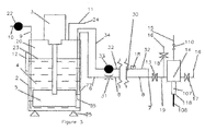
- FIG. 1 shows a cutting head 14 that generates a cutting jet 108.
- Pressurised water from a source 15 flows via pressurised water shut off valve 110 and collimation tube 102 to a waterjet nozzle 103 to produce a high velocity waterjet 104.
- the waterjet 104 traverses an entrainment chamber 105 and enters the bore 106 of a focus tube 107.
- the waterjet 104 entrains abrasive suspension from source 100 through conduit 19, with abrasive suspension on/off valve 13 to passageway 111 and into entrainment chamber 105 and focus tube bore 106.
- momentum is exchanged between the waterjet 104 and abrasive particles and water in abrasive suspension to generate the cutting jet 108 at a focus tube outlet 118.
- a source of displacement fluid 16 at above atmospheric pressure may be provided through valve 17, tubing 117 and passageway 112 to entrainment chamber 105 or a source of displacement fluid 16 may be provided through valve 18 to conduit 19 between abrasive suspension on/off valve 13 and cutting head passageway 111.
- the displacement fluid will usually be water although in some circumstances pressurised air may be preferable.
- the pressure of abrasive suspension from source 100 needs to be at a pressure below atmospheric to achieve desired abrasive concentrations in cutting jet 108. If pressurised water shut off valve 110 is closed and abrasive suspension on/off valve 13 is open and if separate source of displacement fluid 16 is not provided or valves 17 and 18 are closed, ambient fluid at 118 is drawn in focus tube bore 106. The ambient fluid drawn in at 118 is air unless focus tube 107 is submerged when water is drawn in. The fluid drawn into focus tube bore 106 flows through entrainment chamber 105, passageway 111 and conduit 19 towards the abrasive suspension source 100.
- valve 17 or 18 displacement fluid from source 16 flows towards the abrasive suspension source 100.
- pressurised displacement fluid flowing through valve 17 it passes through tubing 117, passageway 112, entrainment chamber 105, passageway 111, and conduit 19 with abrasive suspension on/off valve 13 displacing abrasive suspension towards the source of abrasive suspension 100.
- entrainment chamber 105 part of the displacement fluid also flows through focus tube bore 106 to discharge at focus tube outlet 118.
- displacement fluid from a source 16 enters through valve 18 to conduit 19 it flows towards the source of abrasive suspension 100 through valve 13 and also towards the focus tube outlet 118 through passageway 111, entrainment chamber 105 and focus tube bore 106.
- the flow of displacement water from a source 16 may be varied so as to change the characteristics of the waterjet at the focus tube 107 outlet 118.
- the amount of water flowing from source 16 can increase or decrease the intensity of cavitation on a workpiece close to the focus tube 107 outlet 118.
- the ability to vary cavitation intensity can be useful in marking and etching workpiece surfaces.
- abrasive waterjet 104 When an abrasive waterjet 104 is entraining abrasive suspension the concentration of abrasive in cutting jet 108 can be reduced by metering displacement water from source 16 through valve 17 or 18. In the case of displacement water metered through valve 17 rapid changes in abrasive concentration in cutting jet 108 are possible to provide control of material removal during etching and milling.
- Hopper 2 shows an abrasive suspension feed circuit 1 for an entrainment cutting head 14.
- Hopper 2 has an agitator 3 with stirrer 5 and is partially filled with abrasive/water mixture 4 with an abrasive content of typically 60 to 70wt%.
- Hopper 2 is topped up with abrasive suspension from source 10 through pump 22 and conduit 9.
- Hopper 2 is sealed from the environment and air space 20 is connected via conduit 23 to a vacuum source 21.
- Abrasive suspension 4 enters conduit 19 with abrasive suspension on/off valve 13 at point 7.
- valve 110 open to pressurised water source 15, and valve 13 open a waterjet 104 in cutting head 14 entrains abrasive suspension from hopper 2 at 7 via conduit 19 to entrainment chamber 104 of cutting head 14.
- the rate of abrasive suspension flow is dependent on the abrasive suspension rheological properties at point 7, on the pressure loss characteristics of the flow line between point 7 and entrainment chamber 104 and on the pressure differential between point 7 and entrainment chamber 104.
- the pressure at point 7 is controlled by the vacuum source 21.
- point 7 may be regarded as a source of abrasive suspension which may be arranged in fluid communication with the cutting head 14 via the conduit 19.
- a source of displacement fluid 16 may be connected via valve 17 to entrainment chamber 105 of cutting head 14 or connected via valve 18 to conduit 19.
- conduit 19 can be essentially emptied of abrasive suspension when abrasive suspension shut off valve 13 is open and valve 18 or 17 are open to a source of displacement fluid 16 at a pressure above atmospheric pressure. Part of the displacement fluid also flows through focus tube 107.
- displacement fluid from the environment at focus tube 107 outlet 118 enters a focus tube when valve 110 is closed and valve 13 open and there is a vacuum in space 20 in hopper 2.
- the displacement fluid is air unless a focus tube 107 outlet is submerged in water when the displacement fluid is water.
- the displacement fluid flows through conduit 19 to discharge into hopper 2 at point 7.
- valve 13 is desirably scheduled to be open for a time just sufficient to allow abrasive suspension to be cleared from conduit 19.
- valve 13 is desirably scheduled to be open for a time just sufficient for displacement water to clear abrasive suspension from conduit 19.
- Valve 13 may be located at point 7 to conduit 19 to avoid programming periodic opening and closing of valve 13 to flush migrating and dewatering abrasive that enters conduit 19 at point 7 after initial clearing of abrasive suspension from conduit 19.
- abrasive suspension 4 in hopper 2 may be maintained in a suitable condition without agitator 3 and stirrer 5. Instead it can be arranged that abrasive suspension 4 is cyclically pumped into and out of hopper 2 by pump 22, whilst maintaining sufficient abrasive suspension 4 in hopper 2 to supply abrasive suspension 4 to cutting head 14.
- FIG. 3 shows an abrasive suspension feed system 30 in which substantially more abrasive suspension is pumped in a flow circuit passing close to a cutting head 14 than is required by a cutting head.
- the flow circuit is formed by conduit 6 with inlet 77 and variable flow restriction 31, conduit 8, a junction at point 7, conduit 32, pump 33 and conduit 34 with outlet 35 from the flow circuit in hopper 2.
- junction point 7 may be regarded as a source of abrasive suspension which may be arranged in fluid communication with the cutting head 14 via conduit 19.
- the flow direction in the flow circuit may be reversed so that the pressure at junction 7 can be above or below the pressure acting on the surface 23 in hopper 2. Reversal of flow direction may be necessary if a blockage occurs in the flow circuit.
- the pressure at junction point 7 is controlled by varying the speed of pump 33, by the setting of restriction 31, by the abrasive suspension surface level 23 in hopper 2 relative to cutting head 14 and by the pressure in air space 20 acting on surface 23.
- the pressure in air space 20 is the air source pressure 24 connected through conduit 11 and is preferably atmospheric pressure.
- a pressure sensor 18 located close to junction point 7 provides a signal for setting the pressure at junction point 7.
- hopper 2 of Figure 3 Operation of hopper 2 of Figure 3 is generally as for hopper 2 of Figure 2 as is the function of valves 13, 17 and 18.
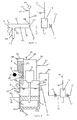
- FIG. 4 shows part of an abrasive suspension feed system 70 that with part of an abrasive suspension feed system 40 of Figure 5 forms a complete abrasive suspension feed system.
- FIG. 4 shows that a layer of cover water 73 is provided above a suspended abrasive bed 72.
- An agitator 51 with impeller 50 is adapted to stir the bed 72.
- a weight sensor 55 comprising a load cell 25 is mounted to the hopper 71, and is vertically movable (double arrow 56) depending on the change of load. The vertical movement may be used as an output to a control system (not shown) for adding dry abrasive powder particles, or controlling the rate at which the impeller 50 is lowered into the bed 72 during start up.
- Dry abrasive powder particles are contained in a silo 60 which is mounted in a holder 61.
- a valve 69 in a discharge pipe 63 is opened and a vibrator 62 is actuated to provide vibrations to the holder 61, whereby the powder particles fall down to the surface 54 of the cover water 73 and descend in a density current to the agitated abrasive bed 72 with little mixing with the cover water 73.
- Water from a water source 64 through connection 65 may be bled into the abrasive bed 72 at a controlled rate and appropriate location to help maintain the desired abrasive concentration at inlet 77 where abrasive suspension is withdrawn from the bed 72.
- Figure 4 also shows an overflow 52 at the top portion of the hopper 71. Excess water flowing up through the bed 72 over flows at the cover water surface 54 to maintain a set water level allowing continuous calculation of the weight of abrasive in the hopper 71 and to carry away material in the abrasive feed that does not wet and floats on the cover water surface 54.
- FIG. 5 shows part of abrasive suspension feed system 30 of Figure 3 but with additional features that makes it particularly suitable for use with the abrasive suspension hopper 71 of Figure 4 .
- abrasive suspension valve 13 of Figure 3 is replaced by valve 45 located at junction point 7.
- abrasive suspension vacuum pressures that can fall below 400 mm Hg is difficult because abrasive accumulates in connections to and the space within a pressure gauge or pressure transducer.
- topping up water entering conduit 32 the pressure at junction point 7 can be inferred without abrasive suspension being in direct contact with a pressure transducer.
- Topping up water from source 47 flows through valve 46, conduit 39 to a non-return valve 48 that prevents abrasive suspension entering conduit 39 from conduit 32.
- Non-return valve 48 may be of a duckbill or similar valve made of polymeric material with a low pressure drop.
- Pressure sensor 49 measures the pressure in conduit 39, which is essentially the pressure at junction point 7 that controls the flow of abrasive suspension to cutting head 14.
- Conduit 44 is attached by flexible joints 41 and 42 to conduit 8.
- a load cell 43 is used to determine the change in weight between water flow through conduit 44 and abrasive suspension flow allowing a calculation of suspension density.
- FIG. 6 shows a suspension feed system 80 that has features of feed system 1 of Figure 1 and of hopper 71 of Figure 4 .
- a dry abrasive powder silo 81 is connected to hopper 89 to allow topping up of hopper 89 with dry abrasive powder 83 in a manner similar to topping up hopper 71 of Figure 4 but with a vacuum in air space 20 above the cover water 73.
- Silo 81 has sealable lid 82 to allow filling up silo 81 with abrasive powder 83.
- Conduit 86 with isolation valve 85 allow pressures in air space 90 in silo 81 to be equalised with the pressure in airspace 20 in hopper 89 provided by vacuum source 21 through conduit 23.
- Powder valve 87 is opened when pressures in air spaces 20 and 90 are equalised. With powder valve 87 open actuation of vibrator 62 cause abrasive powder 83 to flow from silo 81 through connection 88 and fall onto cover water 73 surface 54.
- valves 85 and 87 closed and valve 84 open the pressure across sealable lid 82 is equalised and the lid 82 can be opened to top up silo 81 with abrasive powder 83.
- stirrer 5 When rotation of stirrer 5 is to be stopped for a time period sufficiently long that abrasive bed 72 could settle the majority of the bed 72 may be removed through conduit 92 with inlet at 93 by pump 10 to storage source 91.
- an additive that prevents firm settling of abrasive particles may be introduced into bed 72 from source 91 or by other means to allow stirrer 5 to start rotation in a settled bed 72 without excessive torque.
- a signal from level sensor 94 along with the output from load cell 25 can be used to maintain the cover water level 54 from water source 96 through connection 97 and to control topping up abrasive bed 72 with abrasive from silo 81.
- An abrasive waterjet apparatus for machining forms part of a machine tool.
- the machine tool is required to be highly automated and this includes the abrasive feed system. Except for the filling of a bulk hopper with dry abrasive powder all abrasive suspension feed system functions need to be automated and controlled by the machine tool control system through the control system of the abrasive waterjet apparatus. Automation extends from initiating start up actions that make abrasive suspension of a specified concentration available close to a cutting head to the shutting down of a feed system for an extended period in such a manner as to allow automated start-up of the system at a later date.
- the preferred abrasive suspension feed system embodiment of this invention shown in Figures 4 and 5 , is particularly suited to automated operation.
- Abrasive feed system tubing is arranged to have quick connect and disconnect connections including the tubing for the peristaltic pump to allow easy access to flush abrasive suspension from a flow circuit following loss of power.
Landscapes
- Engineering & Computer Science (AREA)
- Mechanical Engineering (AREA)
- Perforating, Stamping-Out Or Severing By Means Other Than Cutting (AREA)
Applications Claiming Priority (2)
| Application Number | Priority Date | Filing Date | Title |
|---|---|---|---|
| GBGB1204253.7A GB201204253D0 (en) | 2012-03-11 | 2012-03-11 | Abrasive suspension feed system |
| PCT/EP2013/054488 WO2013135538A1 (en) | 2012-03-11 | 2013-03-06 | An abrasive jet system |
Publications (2)
| Publication Number | Publication Date |
|---|---|
| EP2825351A1 EP2825351A1 (en) | 2015-01-21 |
| EP2825351B1 true EP2825351B1 (en) | 2016-03-02 |
Family
ID=46026337
Family Applications (1)
| Application Number | Title | Priority Date | Filing Date |
|---|---|---|---|
| EP13707641.0A Active EP2825351B1 (en) | 2012-03-11 | 2013-03-06 | An abrasive jet system |
Country Status (7)
| Country | Link |
|---|---|
| US (1) | US10252399B2 (enExample) |
| EP (1) | EP2825351B1 (enExample) |
| JP (1) | JP6211544B2 (enExample) |
| CN (1) | CN104271316A (enExample) |
| GB (1) | GB201204253D0 (enExample) |
| IN (1) | IN2014DN08028A (enExample) |
| WO (1) | WO2013135538A1 (enExample) |
Families Citing this family (24)
| Publication number | Priority date | Publication date | Assignee | Title |
|---|---|---|---|---|
| WO2015149867A1 (de) * | 2014-04-04 | 2015-10-08 | Ant Applied New Technologies Ag | Wasser-abrasiv-suspensions-schneidanlage |
| DE102015000632A1 (de) * | 2015-01-22 | 2016-07-28 | Sentenso Gmbh | Regelung des Strahlmitteldurchsatzes einer Strahlanlage |
| CN105643468A (zh) * | 2016-01-26 | 2016-06-08 | 中国矿业大学 | 一种超高压喷射机及其工作方法 |
| CN106194092B (zh) * | 2016-07-26 | 2018-07-24 | 中国海洋石油总公司 | 高压磨料射流海上套管切割状态判别方法 |
| IT201600097457A1 (it) * | 2016-09-28 | 2018-03-28 | Eurowaterjet S R L | Apparato per il taglio a getto d’acqua |
| US11577366B2 (en) | 2016-12-12 | 2023-02-14 | Omax Corporation | Recirculation of wet abrasive material in abrasive waterjet systems and related technology |
| CA3058487A1 (en) * | 2017-03-31 | 2018-10-04 | Ant Applied New Technologies Ag | Water-abrasive-suspension cutting system |
| JP7050806B2 (ja) | 2017-03-31 | 2022-04-08 | エーエヌティー アプライド ニュー テクノロジーズ エージー | ウォータアブレイシブサスペンションジェット式切断装置およびウォータアブレイシブサスペンションジェット式切断方法 |
| JP6959157B2 (ja) * | 2018-01-31 | 2021-11-02 | 三菱重工業株式会社 | 加工装置、及び加工方法 |
| US11224987B1 (en) | 2018-03-09 | 2022-01-18 | Omax Corporation | Abrasive-collecting container of a waterjet system and related technology |
| US11318581B2 (en) * | 2018-05-25 | 2022-05-03 | Flow International Corporation | Abrasive fluid jet cutting systems, components and related methods for cutting sensitive materials |
| IT201800011036A1 (it) * | 2018-12-12 | 2020-06-12 | Bicarjet S R L | Sabbiatrice con sistema di controllo del caricamento di materiale abrasivo |
| CN109434695B (zh) * | 2018-12-18 | 2024-06-21 | 江苏富技腾机电科技有限公司 | 一种水切割机的供沙装置及水切割机 |
| WO2021021947A1 (en) | 2019-07-29 | 2021-02-04 | Omax Corporation | Measuring abrasive flow rates in a conduit |
| US12403621B2 (en) | 2019-12-20 | 2025-09-02 | Hypertherm, Inc. | Motorized systems and associated methods for controlling an adjustable dump orifice on a liquid jet cutting system |
| US20210245328A1 (en) * | 2020-02-10 | 2021-08-12 | Enfield Engine Company, Inc. | Abrasive solvent jet cutting system and method |
| IT202000006010A1 (it) * | 2020-03-20 | 2021-09-20 | Milano Politecnico | Macchina da taglio a getto d’acqua abrasivo |
| KR20230005840A (ko) | 2020-03-30 | 2023-01-10 | 하이퍼썸, 인크. | 다기능 접속 종방향 단부들을 갖는 액체 제트 펌프를 위한 실린더 |
| CN112428151A (zh) * | 2020-11-12 | 2021-03-02 | 上海狮迈科技有限公司 | 一种带有真空辅助的磨料水射流控制系统、方法及切割机 |
| CN113137607B (zh) * | 2021-04-25 | 2022-01-11 | 浙江宏电环保装备有限公司 | 一种废气颗粒处理装置及其使用方法 |
| CN113561072A (zh) * | 2021-08-30 | 2021-10-29 | 河南理工大学 | 浆液磨料水射流自动比例加料装置 |
| CN114034465B (zh) * | 2021-11-11 | 2023-09-19 | 中国石油大学(华东) | 一种前混合泡沫磨料射流破岩实验系统及实验方法 |
| IT202100030488A1 (it) * | 2021-12-01 | 2023-06-01 | Sacmi | Metodo di taglio di uno strato di materiale ceramico in polvere e processo ed impianto di realizzazione di articoli ceramici |
| CN114700880B (zh) * | 2022-03-24 | 2024-03-26 | 重庆大学 | 一种用于磨料射流设备的磨料质量浓度检测系统及方法 |
Family Cites Families (21)
| Publication number | Priority date | Publication date | Assignee | Title |
|---|---|---|---|---|
| GB8524982D0 (en) * | 1985-10-10 | 1985-11-13 | British Hydromechanics | Supply abrasive material |
| CA1298708C (en) * | 1985-10-10 | 1992-04-14 | Roger Artinade Heron | Feeding abrasive material |
| KR930008692B1 (ko) | 1986-02-20 | 1993-09-13 | 가와사끼 쥬고교 가부시기가이샤 | 어브레시브 워터 제트 절단방법 및 장치 |
| US4862649A (en) * | 1986-08-28 | 1989-09-05 | Ltv Aerospace & Defense Co. | Material transfer system |
| JPH0544048Y2 (enExample) * | 1988-10-28 | 1993-11-08 | ||
| IT1249665B (it) * | 1991-06-19 | 1995-03-09 | Cie Dentalfarm S R L | Sistema di microsabbiatura e valvola pneumatica utilizzata in tale sistema |
| GB2264659B (en) * | 1992-02-29 | 1995-05-24 | Rolls Royce Plc | Abrasive fluid jet machining |
| JP2710117B2 (ja) * | 1993-06-17 | 1998-02-10 | 澁谷工業株式会社 | ウォータージェット加工機の研磨材供給装置 |
| US5718581A (en) * | 1995-05-09 | 1998-02-17 | Danville Manufacturing, Inc. | Air abrasive particle apparatus |
| US5643058A (en) * | 1995-08-11 | 1997-07-01 | Flow International Corporation | Abrasive fluid jet system |
| GB9719550D0 (en) * | 1997-09-16 | 1997-11-19 | Miller Donald S | Fluid abrasive jets for machining |
| US20030092364A1 (en) * | 2001-11-09 | 2003-05-15 | International Business Machines Corporation | Abrasive fluid jet cutting composition, method and apparatus |
| US6956063B2 (en) * | 2001-12-28 | 2005-10-18 | Conocophillips Company | Method for reducing water concentration in a multi-phase column reactor |
| US20040132383A1 (en) * | 2002-08-14 | 2004-07-08 | Langford Mark A. | Fluid jet cutting system |
| SG111988A1 (en) * | 2003-04-02 | 2005-06-29 | Jetsis Int Pte Ltd | Switching fluid flow by diversion |
| AT9123U1 (de) | 2006-02-22 | 2007-05-15 | Boehler Hochdrucktech Gmbh | Einrichtung für wasserstrahl- oder abrasivwasserstrahl-schneidanlagen |
| GB0624892D0 (en) * | 2006-12-14 | 2007-01-24 | Miller Donald S | Plunger pump |
| US7934977B2 (en) | 2007-03-09 | 2011-05-03 | Flow International Corporation | Fluid system and method for thin kerf cutting and in-situ recycling |
| CN201385260Y (zh) * | 2009-02-24 | 2010-01-20 | 任保林 | 高压前混合式悬浮磨料水射流切割及清洗装置 |
| CN101537600A (zh) * | 2009-04-30 | 2009-09-23 | 中国矿业大学(北京) | 矿用磨料水射流切割方法及装置 |
| GB0921681D0 (en) | 2009-12-11 | 2010-01-27 | Miller Donald S | Structural waterjet element |
-
2012
- 2012-03-11 GB GBGB1204253.7A patent/GB201204253D0/en not_active Ceased
-
2013
- 2013-03-06 US US14/383,662 patent/US10252399B2/en active Active
- 2013-03-06 CN CN201380024039.0A patent/CN104271316A/zh active Pending
- 2013-03-06 JP JP2014560351A patent/JP6211544B2/ja active Active
- 2013-03-06 EP EP13707641.0A patent/EP2825351B1/en active Active
- 2013-03-06 WO PCT/EP2013/054488 patent/WO2013135538A1/en not_active Ceased
-
2014
- 2014-09-25 IN IN8028DEN2014 patent/IN2014DN08028A/en unknown
Also Published As
| Publication number | Publication date |
|---|---|
| GB201204253D0 (en) | 2012-04-25 |
| EP2825351A1 (en) | 2015-01-21 |
| JP6211544B2 (ja) | 2017-10-11 |
| JP2015512793A (ja) | 2015-04-30 |
| WO2013135538A1 (en) | 2013-09-19 |
| IN2014DN08028A (enExample) | 2015-05-01 |
| US10252399B2 (en) | 2019-04-09 |
| CN104271316A (zh) | 2015-01-07 |
| US20150031270A1 (en) | 2015-01-29 |
Similar Documents
| Publication | Publication Date | Title |
|---|---|---|
| EP2825351B1 (en) | An abrasive jet system | |
| US20200215502A1 (en) | Mixing System for Cement and Fluids | |
| US9334175B2 (en) | Method and apparatus for treatment of fluids | |
| US20240408723A1 (en) | Abrasive suspension jet cutting system having reduced system wear and process materials reclamation | |
| US8511886B2 (en) | Mixing apparatus and method of using same | |
| CN101506464A (zh) | 用于制备回注到钻井中的钻屑的方法和设备 | |
| WO2013074878A1 (en) | Mixing methods and systems for fluids | |
| CN104487715A (zh) | 操作多相泵及其设备的方法 | |
| US20150204165A1 (en) | Apparatus and method for continuously mixing fluids using dry additives | |
| US9795939B2 (en) | Apparatus for mixing and blending of an additive material into a fluid and method | |
| CN107552252B (zh) | 餐厨垃圾用砂浆分离设备 | |
| CA2839611A1 (en) | Apparatus and method for continuously mixing fluids using dry additives | |
| JP2017077554A (ja) | 微細物の移送方法、微細物の移送装置、微細物の溶解方法、および微細物の溶解装置 | |
| CN115970529B (zh) | 一种固液分离试验装置 | |
| CN100520627C (zh) | 粉末调色剂传输方法及传输装置、填充方法及填充装置 | |
| JPH10230151A (ja) | 粉体の懸濁・溶解装置 | |
| JP4321715B2 (ja) | 地盤改良工法 | |
| RU2499878C1 (ru) | Способ приготовления бурильных промывочных и тампонажных растворов и устройство для его осуществления | |
| RU98221U1 (ru) | Автономный блок приготовления буровых и тампонажных растворов | |
| CN221360377U (zh) | 一种切入式螺旋润湿的煤泥分选装置 | |
| KR101497418B1 (ko) | 머드 응고 방지장치 | |
| UA82202C2 (uk) | Спосіб транспортування гідросуміші з великих глибин та пристрій для його реалізації | |
| RU2310099C2 (ru) | Способ транспортирования гидросмеси с больших глубин и устройство для его реализации | |
| UA67246C2 (uk) | Спосіб транспортування гідросуміші і пристрій для його реалізації | |
| EP2834419B1 (en) | Method and arrangement for producing gravel columns |
Legal Events
| Date | Code | Title | Description |
|---|---|---|---|
| PUAI | Public reference made under article 153(3) epc to a published international application that has entered the european phase |
Free format text: ORIGINAL CODE: 0009012 |
|
| 17P | Request for examination filed |
Effective date: 20140916 |
|
| AK | Designated contracting states |
Kind code of ref document: A1 Designated state(s): AL AT BE BG CH CY CZ DE DK EE ES FI FR GB GR HR HU IE IS IT LI LT LU LV MC MK MT NL NO PL PT RO RS SE SI SK SM TR |
|
| AX | Request for extension of the european patent |
Extension state: BA ME |
|
| DAX | Request for extension of the european patent (deleted) | ||
| GRAP | Despatch of communication of intention to grant a patent |
Free format text: ORIGINAL CODE: EPIDOSNIGR1 |
|
| INTG | Intention to grant announced |
Effective date: 20150910 |
|
| GRAS | Grant fee paid |
Free format text: ORIGINAL CODE: EPIDOSNIGR3 |
|
| GRAA | (expected) grant |
Free format text: ORIGINAL CODE: 0009210 |
|
| AK | Designated contracting states |
Kind code of ref document: B1 Designated state(s): AL AT BE BG CH CY CZ DE DK EE ES FI FR GB GR HR HU IE IS IT LI LT LU LV MC MK MT NL NO PL PT RO RS SE SI SK SM TR |
|
| REG | Reference to a national code |
Ref country code: GB Ref legal event code: FG4D |
|
| REG | Reference to a national code |
Ref country code: AT Ref legal event code: REF Ref document number: 777671 Country of ref document: AT Kind code of ref document: T Effective date: 20160315 Ref country code: CH Ref legal event code: EP |
|
| REG | Reference to a national code |
Ref country code: IE Ref legal event code: FG4D |
|
| REG | Reference to a national code |
Ref country code: DE Ref legal event code: R096 Ref document number: 602013005243 Country of ref document: DE |
|
| REG | Reference to a national code |
Ref country code: CH Ref legal event code: NV Representative=s name: OFFICE ERNEST T. FREYLINGER S.A., CH |
|
| REG | Reference to a national code |
Ref country code: FR Ref legal event code: PLFP Year of fee payment: 4 |
|
| REG | Reference to a national code |
Ref country code: SE Ref legal event code: TRGR |
|
| REG | Reference to a national code |
Ref country code: NL Ref legal event code: MP Effective date: 20160302 |
|
| REG | Reference to a national code |
Ref country code: LT Ref legal event code: MG4D |
|
| REG | Reference to a national code |
Ref country code: AT Ref legal event code: MK05 Ref document number: 777671 Country of ref document: AT Kind code of ref document: T Effective date: 20160302 |
|
| PG25 | Lapsed in a contracting state [announced via postgrant information from national office to epo] |
Ref country code: FI Free format text: LAPSE BECAUSE OF FAILURE TO SUBMIT A TRANSLATION OF THE DESCRIPTION OR TO PAY THE FEE WITHIN THE PRESCRIBED TIME-LIMIT Effective date: 20160302 Ref country code: NO Free format text: LAPSE BECAUSE OF FAILURE TO SUBMIT A TRANSLATION OF THE DESCRIPTION OR TO PAY THE FEE WITHIN THE PRESCRIBED TIME-LIMIT Effective date: 20160602 Ref country code: GR Free format text: LAPSE BECAUSE OF FAILURE TO SUBMIT A TRANSLATION OF THE DESCRIPTION OR TO PAY THE FEE WITHIN THE PRESCRIBED TIME-LIMIT Effective date: 20160603 Ref country code: ES Free format text: LAPSE BECAUSE OF FAILURE TO SUBMIT A TRANSLATION OF THE DESCRIPTION OR TO PAY THE FEE WITHIN THE PRESCRIBED TIME-LIMIT Effective date: 20160302 Ref country code: HR Free format text: LAPSE BECAUSE OF FAILURE TO SUBMIT A TRANSLATION OF THE DESCRIPTION OR TO PAY THE FEE WITHIN THE PRESCRIBED TIME-LIMIT Effective date: 20160302 |
|
| PG25 | Lapsed in a contracting state [announced via postgrant information from national office to epo] |
Ref country code: AT Free format text: LAPSE BECAUSE OF FAILURE TO SUBMIT A TRANSLATION OF THE DESCRIPTION OR TO PAY THE FEE WITHIN THE PRESCRIBED TIME-LIMIT Effective date: 20160302 Ref country code: BE Free format text: LAPSE BECAUSE OF NON-PAYMENT OF DUE FEES Effective date: 20160331 Ref country code: LT Free format text: LAPSE BECAUSE OF FAILURE TO SUBMIT A TRANSLATION OF THE DESCRIPTION OR TO PAY THE FEE WITHIN THE PRESCRIBED TIME-LIMIT Effective date: 20160302 Ref country code: RS Free format text: LAPSE BECAUSE OF FAILURE TO SUBMIT A TRANSLATION OF THE DESCRIPTION OR TO PAY THE FEE WITHIN THE PRESCRIBED TIME-LIMIT Effective date: 20160302 Ref country code: LV Free format text: LAPSE BECAUSE OF FAILURE TO SUBMIT A TRANSLATION OF THE DESCRIPTION OR TO PAY THE FEE WITHIN THE PRESCRIBED TIME-LIMIT Effective date: 20160302 Ref country code: PL Free format text: LAPSE BECAUSE OF FAILURE TO SUBMIT A TRANSLATION OF THE DESCRIPTION OR TO PAY THE FEE WITHIN THE PRESCRIBED TIME-LIMIT Effective date: 20160302 Ref country code: NL Free format text: LAPSE BECAUSE OF FAILURE TO SUBMIT A TRANSLATION OF THE DESCRIPTION OR TO PAY THE FEE WITHIN THE PRESCRIBED TIME-LIMIT Effective date: 20160302 |
|
| PG25 | Lapsed in a contracting state [announced via postgrant information from national office to epo] |
Ref country code: IS Free format text: LAPSE BECAUSE OF FAILURE TO SUBMIT A TRANSLATION OF THE DESCRIPTION OR TO PAY THE FEE WITHIN THE PRESCRIBED TIME-LIMIT Effective date: 20160702 Ref country code: EE Free format text: LAPSE BECAUSE OF FAILURE TO SUBMIT A TRANSLATION OF THE DESCRIPTION OR TO PAY THE FEE WITHIN THE PRESCRIBED TIME-LIMIT Effective date: 20160302 |
|
| PG25 | Lapsed in a contracting state [announced via postgrant information from national office to epo] |
Ref country code: RO Free format text: LAPSE BECAUSE OF FAILURE TO SUBMIT A TRANSLATION OF THE DESCRIPTION OR TO PAY THE FEE WITHIN THE PRESCRIBED TIME-LIMIT Effective date: 20160302 Ref country code: SK Free format text: LAPSE BECAUSE OF FAILURE TO SUBMIT A TRANSLATION OF THE DESCRIPTION OR TO PAY THE FEE WITHIN THE PRESCRIBED TIME-LIMIT Effective date: 20160302 Ref country code: PT Free format text: LAPSE BECAUSE OF FAILURE TO SUBMIT A TRANSLATION OF THE DESCRIPTION OR TO PAY THE FEE WITHIN THE PRESCRIBED TIME-LIMIT Effective date: 20160704 Ref country code: CZ Free format text: LAPSE BECAUSE OF FAILURE TO SUBMIT A TRANSLATION OF THE DESCRIPTION OR TO PAY THE FEE WITHIN THE PRESCRIBED TIME-LIMIT Effective date: 20160302 Ref country code: SM Free format text: LAPSE BECAUSE OF FAILURE TO SUBMIT A TRANSLATION OF THE DESCRIPTION OR TO PAY THE FEE WITHIN THE PRESCRIBED TIME-LIMIT Effective date: 20160302 |
|
| REG | Reference to a national code |
Ref country code: DE Ref legal event code: R097 Ref document number: 602013005243 Country of ref document: DE |
|
| REG | Reference to a national code |
Ref country code: IE Ref legal event code: MM4A |
|
| PG25 | Lapsed in a contracting state [announced via postgrant information from national office to epo] |
Ref country code: BE Free format text: LAPSE BECAUSE OF FAILURE TO SUBMIT A TRANSLATION OF THE DESCRIPTION OR TO PAY THE FEE WITHIN THE PRESCRIBED TIME-LIMIT Effective date: 20160302 Ref country code: IT Free format text: LAPSE BECAUSE OF FAILURE TO SUBMIT A TRANSLATION OF THE DESCRIPTION OR TO PAY THE FEE WITHIN THE PRESCRIBED TIME-LIMIT Effective date: 20160302 |
|
| PLBE | No opposition filed within time limit |
Free format text: ORIGINAL CODE: 0009261 |
|
| STAA | Information on the status of an ep patent application or granted ep patent |
Free format text: STATUS: NO OPPOSITION FILED WITHIN TIME LIMIT |
|
| PG25 | Lapsed in a contracting state [announced via postgrant information from national office to epo] |
Ref country code: DK Free format text: LAPSE BECAUSE OF FAILURE TO SUBMIT A TRANSLATION OF THE DESCRIPTION OR TO PAY THE FEE WITHIN THE PRESCRIBED TIME-LIMIT Effective date: 20160302 Ref country code: IE Free format text: LAPSE BECAUSE OF NON-PAYMENT OF DUE FEES Effective date: 20160306 |
|
| 26N | No opposition filed |
Effective date: 20161205 |
|
| PG25 | Lapsed in a contracting state [announced via postgrant information from national office to epo] |
Ref country code: BG Free format text: LAPSE BECAUSE OF FAILURE TO SUBMIT A TRANSLATION OF THE DESCRIPTION OR TO PAY THE FEE WITHIN THE PRESCRIBED TIME-LIMIT Effective date: 20160602 Ref country code: SI Free format text: LAPSE BECAUSE OF FAILURE TO SUBMIT A TRANSLATION OF THE DESCRIPTION OR TO PAY THE FEE WITHIN THE PRESCRIBED TIME-LIMIT Effective date: 20160302 |
|
| PG25 | Lapsed in a contracting state [announced via postgrant information from national office to epo] |
Ref country code: MT Free format text: LAPSE BECAUSE OF FAILURE TO SUBMIT A TRANSLATION OF THE DESCRIPTION OR TO PAY THE FEE WITHIN THE PRESCRIBED TIME-LIMIT Effective date: 20160302 |
|
| REG | Reference to a national code |
Ref country code: FR Ref legal event code: PLFP Year of fee payment: 5 |
|
| REG | Reference to a national code |
Ref country code: FR Ref legal event code: PLFP Year of fee payment: 6 |
|
| PG25 | Lapsed in a contracting state [announced via postgrant information from national office to epo] |
Ref country code: HU Free format text: LAPSE BECAUSE OF FAILURE TO SUBMIT A TRANSLATION OF THE DESCRIPTION OR TO PAY THE FEE WITHIN THE PRESCRIBED TIME-LIMIT; INVALID AB INITIO Effective date: 20130306 |
|
| PG25 | Lapsed in a contracting state [announced via postgrant information from national office to epo] |
Ref country code: MC Free format text: LAPSE BECAUSE OF FAILURE TO SUBMIT A TRANSLATION OF THE DESCRIPTION OR TO PAY THE FEE WITHIN THE PRESCRIBED TIME-LIMIT Effective date: 20160302 Ref country code: MT Free format text: LAPSE BECAUSE OF FAILURE TO SUBMIT A TRANSLATION OF THE DESCRIPTION OR TO PAY THE FEE WITHIN THE PRESCRIBED TIME-LIMIT Effective date: 20160331 Ref country code: CY Free format text: LAPSE BECAUSE OF FAILURE TO SUBMIT A TRANSLATION OF THE DESCRIPTION OR TO PAY THE FEE WITHIN THE PRESCRIBED TIME-LIMIT Effective date: 20160302 Ref country code: MK Free format text: LAPSE BECAUSE OF FAILURE TO SUBMIT A TRANSLATION OF THE DESCRIPTION OR TO PAY THE FEE WITHIN THE PRESCRIBED TIME-LIMIT Effective date: 20160302 Ref country code: LU Free format text: LAPSE BECAUSE OF NON-PAYMENT OF DUE FEES Effective date: 20160306 |
|
| PG25 | Lapsed in a contracting state [announced via postgrant information from national office to epo] |
Ref country code: TR Free format text: LAPSE BECAUSE OF FAILURE TO SUBMIT A TRANSLATION OF THE DESCRIPTION OR TO PAY THE FEE WITHIN THE PRESCRIBED TIME-LIMIT Effective date: 20160302 Ref country code: AL Free format text: LAPSE BECAUSE OF FAILURE TO SUBMIT A TRANSLATION OF THE DESCRIPTION OR TO PAY THE FEE WITHIN THE PRESCRIBED TIME-LIMIT Effective date: 20160302 |
|
| PGFP | Annual fee paid to national office [announced via postgrant information from national office to epo] |
Ref country code: DE Payment date: 20250219 Year of fee payment: 13 |
|
| PGFP | Annual fee paid to national office [announced via postgrant information from national office to epo] |
Ref country code: SE Payment date: 20250217 Year of fee payment: 13 |
|
| PGFP | Annual fee paid to national office [announced via postgrant information from national office to epo] |
Ref country code: FR Payment date: 20250217 Year of fee payment: 13 |
|
| PGFP | Annual fee paid to national office [announced via postgrant information from national office to epo] |
Ref country code: GB Payment date: 20250218 Year of fee payment: 13 |
|
| PGFP | Annual fee paid to national office [announced via postgrant information from national office to epo] |
Ref country code: CH Payment date: 20250401 Year of fee payment: 13 |