EP2825333B1 - Cam follower arrangement - Google Patents
Cam follower arrangement Download PDFInfo
- Publication number
- EP2825333B1 EP2825333B1 EP13711529.1A EP13711529A EP2825333B1 EP 2825333 B1 EP2825333 B1 EP 2825333B1 EP 13711529 A EP13711529 A EP 13711529A EP 2825333 B1 EP2825333 B1 EP 2825333B1
- Authority
- EP
- European Patent Office
- Prior art keywords
- cam follower
- holding element
- cam
- projection
- holding
- Prior art date
- Legal status (The legal status is an assumption and is not a legal conclusion. Google has not performed a legal analysis and makes no representation as to the accuracy of the status listed.)
- Active
Links
Images


Classifications
-
- F—MECHANICAL ENGINEERING; LIGHTING; HEATING; WEAPONS; BLASTING
- F16—ENGINEERING ELEMENTS AND UNITS; GENERAL MEASURES FOR PRODUCING AND MAINTAINING EFFECTIVE FUNCTIONING OF MACHINES OR INSTALLATIONS; THERMAL INSULATION IN GENERAL
- F16H—GEARING
- F16H53/00—Cams or cam-followers, e.g. rollers for gearing mechanisms
- F16H53/06—Cam-followers
-
- B—PERFORMING OPERATIONS; TRANSPORTING
- B21—MECHANICAL METAL-WORKING WITHOUT ESSENTIALLY REMOVING MATERIAL; PUNCHING METAL
- B21D—WORKING OR PROCESSING OF SHEET METAL OR METAL TUBES, RODS OR PROFILES WITHOUT ESSENTIALLY REMOVING MATERIAL; PUNCHING METAL
- B21D51/00—Making hollow objects
- B21D51/16—Making hollow objects characterised by the use of the objects
- B21D51/26—Making hollow objects characterised by the use of the objects cans or tins; Closing same in a permanent manner
- B21D51/2615—Edge treatment of cans or tins
- B21D51/2638—Necking
-
- Y—GENERAL TAGGING OF NEW TECHNOLOGICAL DEVELOPMENTS; GENERAL TAGGING OF CROSS-SECTIONAL TECHNOLOGIES SPANNING OVER SEVERAL SECTIONS OF THE IPC; TECHNICAL SUBJECTS COVERED BY FORMER USPC CROSS-REFERENCE ART COLLECTIONS [XRACs] AND DIGESTS
- Y10—TECHNICAL SUBJECTS COVERED BY FORMER USPC
- Y10T—TECHNICAL SUBJECTS COVERED BY FORMER US CLASSIFICATION
- Y10T74/00—Machine element or mechanism
- Y10T74/21—Elements
- Y10T74/2101—Cams
- Y10T74/2107—Follower
Definitions
- the present invention relates generally to manufacturing machinery, and more particularly to systems employing a cam follower arrangement in a machine assembly.
- Cam follower arrangements may be used in a turret assembly of a machine arrangement to help change a position of a ram assembly, such as a push or die ram assembly, relative to a lateral axis of a shaft of the turret assembly.
- the cam follower arrangement may include cam follower(s) that follow a cam of the turret assembly so that components (e.g. tooling, push plate) connected to the ram assembly may influence an article (e.g. can, container).
- Conventional cam follower arrangements have shorter life spans, e.g. 6000-8000 hours, resulting from the manner in which the cam follower(s) is mounted to the ram assembly.
- One type of conventional cam follower arrangement includes a single cam follower rigidly mounted on a translating element or housing of the ram assembly. Motion of the translating element is controlled by the interaction between the cam follower and cam surfaces of a groove in the cam. A clearance exists between the cam follower diameter and the cam surfaces to allow the cam follower to rotate. Disadvantages result because undesirable skidding may occur between the cam follower and the cam surfaces due to a direction change in translation that causes a direction change in rotation. The undesirable skidding increases when the speed of the shaft increases. Such skidding decreases the life of the turret assembly because it results in unnecessary wear and tear on the cam follower and cam surfaces.
- Another type of conventional cam follower arrangement includes two cam followers rigidly mounted on a translating element or housing of the ram assembly. Motion of the translating element is controlled by interaction between the cam followers and cam surfaces of a rib on the cam.
- the second type of conventional cam follower arrangement maintains a constant rotational direction, but a clearance exists between the cam follower and the cam surfaces to accommodate for variations in the cam follower diameter and rib thickness. Disadvantages result because undesirable skidding may occur due to a direction change in translation, thereby resulting in the cam followers going from not contacting the rib to contacting the rib. The skidding decreases the life of the turret assembly because it results in unnecessary wear and tear on the cam followers and cam surfaces.
- Another type of conventional cam follower arrangement includes two cam followers where the first cam follower rigidly mounts to a translating element or housing of the ram assembly and the second cam follower mounts to a spring between the second cam follower and the translating element. Motion of the translating element is controlled by interaction between the two cam followers and the cam surfaces of a rib on the cam. No clearance exists in the third type of cam follower arrangement. Instead, a spring keeps the cam followers in constant contact with the cam surfaces by accommodating for variations in cam follower diameter and rib thickness. Disadvantages may result because the spring creates a large spring force to counteract the forces created by the acceleration imparted to the translating element by the cam surfaces. For example, the spring force may be between about 667-890 N (150-200 lbf).
- the spring force depends on the dimensional variations within tolerance ranges.
- the spring force is affected by the shape of the cam surfaces and the mass of the translating element, thereby exerting an unnecessary average force on the cam followers and the cam surfaces.
- the unnecessary force may wear down the cam followers and cam surfaces, thereby reducing the life of the turret assembly.
- International patent application, publication number WO 01/44084 A2 shows a device for conveying discrete identities comprising an advanced transfer arm and a container blowing installation provided with said device.
- systems according to aspects of the present invention employ a cam follower arrangement/assembly that minimizes or eliminates skidding while also minimizing the average load exerted on the cam followers and the cam surfaces.
- an embodiment includes the features as defined in claim 1. Preferred embodiments are defined by the dependent claims.
- the present disclosure relates to a cam follower arrangement for use in a machine assembly.
- the cam follower arrangement minimizes or eliminates skidding while also minimizing the average load exerted on cam followers of the cam follower arrangement and the cam surfaces of a cam of the machine assembly.
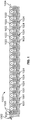
- a machine arrangement 1000 may include a plurality of machine modules 1001 arranged to cooperate with each other.
- the machine arrangement 1000 is shown as a linear machine line in FIG. 1 , embodiments may employ other types of machine lines, such as a recirculated machine line.
- the machine modules 1001 include vertically or horizontally oriented turret assemblies configured to modify articles (e.g., a can, a container, or the like) by performing a working operation (e.g., form, process) on the articles.
- each article After entering the machine arrangement 1000 through an article infeed 1002, each article is received by a turret starwheel 1022 and then travels from the turret starwheel 1022 to a transfer starwheel 1024 and from the transfer starwheel 1024 to another turret starwheel 1022 until the article reaches the article discharge 1004.
- Each starwheel 1020, 1022, 1024 may have any number of pockets 1025 to hold the articles for processing and/or transfer.
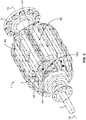
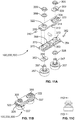
- FIGS. 2-5 illustrate an example turret assembly 1.
- the turret starwheel 1022 is mounted to a starwheel mount 3 of the turret assembly 1. While each article is in the pocket 1025 of the turret starwheel 1022, a ram assembly 40 in the turret assembly 1 performs a working operation on the article at a tooling end 41 of the turret assembly 1.
- the articles may remain stationary along an axis 15-15, while the ram assembly 40 moves along the axis 15-15 relative to the article to engage the article and perform the working operation.
- the axis 15-15 may extend along a shaft 2 of the turret assembly 1.
- the ram assembly 40 includes two cam follower arrangements 100, 200
- the interaction between the cam follower arrangements 100, 200 and respective cams 44, 45 of the turret assembly 1 causes the ram assembly 40 to engage the article and perform the working operation on the article.
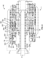
- the cam 44 includes cam/rib surfaces 44a, b that apply a force to the cam follower arrangement 100
- the cam 45 includes cam/rib surfaces 45a, b that apply a force to the cam follower arrangement 200.
- the forces against the cam follower arrangements 100, 200 cause the ram assembly 40 to move as required.
- the ram assembly 40 includes two housings 43, 53 with openings 25, 75 that receive the cam follower arrangements 100, 200, respectively.
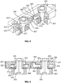
- FIGS. 6 and 7 may employ a ram assembly 340 that includes a single cam follower arrangement 300 as shown in FIGS. 6 and 7 .
- the ram assembly 340 includes one housing 343 with an opening 325 that receives the cam follower arrangement 300.
- each cam follower arrangement may be integrally formed from one piece of material or may be assembled from more than one piece.
- the housing 343 may include a first portion 344 and a second portion 345.
- the first and second portions 344, 345 may be integrally formed from one piece of material or may be assembled from two respective pieces.
- the first portion 344 generally corresponds with the opening 325 for the cam follower arrangement 300 and the second portion 345 generally extends from the cam follower arrangement 300.
- the housing for a cam follower arrangement may include any number of portions having any configuration.
- a housing formed from more than one piece may facilitate assembly with the corresponding cam follower arrangement, but in other embodiments, a housing integrally formed from one piece of material may be stronger and more stable.
- cam follower arrangement generally apply to any individual cam follower arrangement, regardless of the number of cam follower arrangements on a ram assembly. Accordingly, general reference to a cam follower arrangement and its corresponding housing may apply, for example, to any of the cam follower arrangements 100, 200, 300, 400 described herein and its respective housing (e.g., housing 43, 53, and 343).
- Each cam follower arrangement includes a first holding element 304 and a second holding element 354.
- the first and second holding elements 304, 354 are mounted in the housing for the cam follower arrangement.
- a first cam follower 307 is coupled to the first holding element 304
- a second cam follower 357 is coupled to the second holding element 354.
- the first and second holding elements 304, 354 may be substantially identical components that are combined in an interlocking arrangement.
- the first holding element 304 is disposed in a first orientation, while the second holding element 354 is disposed in an opposing, mirroring second orientation.
- first and second holding elements 304, 354 move relative to each other to allow the first and second cam followers 307, 357 to engage a corresponding cam surface in a manner that minimizes or eliminates skidding while also minimizing the average load exerted between the cam followers 307, 357 and the cam surfaces.
- a compressible adjustment element 360 is disposed between the first and second holding elements 304, 354 to determine the relative movement between the first and second holding elements 304, 354.
- the first holding element 304 has an outer edge 337
- the second holding element 354 has an outer edge 377.
- the cam follower arrangement with assembled first and second holding elements 304, 354 are disposed in the housing, there is a varying clearance in the axial direction between the outer edges 337, 377 and the corresponding inner edge of the housing opening.
- the housings 43, 53, 343 have corresponding inner edges 26, 76, 376, respectively.
- the clearance may depend on the size of the ram assembly.
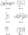
- the cam follower arrangement moves from a working state, where the ram assembly operates on an article, to a non-working state, where the ram assembly is not operating on an article.
- the clearance between the outer edges 337, 377 and the corresponding inner edge of the housing opening may be about 0.012 inches when the cam follower arrangement is in the working state and about 0.10 inches when the cam follower arrangement is in the non-working state.
- the clearance in the non-working state may equal the clearance in the working state (such as 0.012 inches) plus a decompression value (such as 0.090 inches) of the adjusting element 360.
- the clearance When in the working state, the clearance may only exist on one side of the cam follower arrangement.
- the clearance 399 between the outer edge 337 of the holding element 304 and the inner edge 376 of the housing 343 may be about 0.012 inches on one side (left) of the cam follower arrangement 300 and about 0 inches on the other side (right) of the cam follower arrangement 300.
- the driving force applied by the cam surfaces against the cam followers 307, 357 in one direction causes the cam follower arrangement to move in the same direction and abut one side of the housing opening.
- the clearance at this side of the housing opening may decrease to 0 inches.
- the first and second holding elements 304, 354 are configured to move independently, relative to each other.
- the driving force acts to compress the adjustment element 360 between the first and second holding elements 304, 354 and to cause the first and second holding elements 304, 354 to move toward each other.
- the cam follower arrangement is in the non-working position, the first and second holding elements 304, 354 move away from each other due to the decompression of the adjustment element 360 in the absence of the driving force.
- the first holding element 304, 354 includes openings 320, 322 and the second holding element 354 includes openings 370, 372.
- the openings 322 and 370 combine to receive the cam follower 357 and the openings 320 and 372 combine to receive the cam follower 307.
- the openings 320, 370 may be longer in the axial direction than the openings 322, 372.
- the openings 320, 370 and the openings 322, 372 are dimensioned to allow the first holding element 304 and the second holding element 354 to move relative to each other in the axial direction.
- the cam follower 357 coupled to the first holding element 304 via the opening 322 can move axially within the opening 370, while simultaneously the cam follower 307 coupled to the second holding element 354 via the opening 372 can move axially within the opening 320.
- the width and height of the openings 320, 322, 370, 372 may vary depending on the dimensions of the cam follower arrangement.
- the openings 320, 370 may have substantially the same height and width as the openings 322, 372, but the heights and widths may vary as long as they allow the desired relative movement between the first holding element 304 and the second holding element 354.
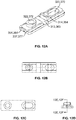
- the openings 320, 370 are configured to receive first and second sliding plates 303, 353, respectively.
- the first and second plates 303, 353 may be substantially similar.
- the first openings 320, 370 may be axially longer than the respective first and second plates 303, 353, so that the first and second plates 303, 353 can move axially within the openings 320, 270.
- the first and second plates 303, 353 move within the first openings 320, 370 when cam follower arrangement transitions from the working state to the non-working state.
- the thickness, length, and width of the first and second plates 303, 353 may vary according to the dimensions of the cam follower arrangement. As FIGS. 14A and 14B illustrate, for example, the thickness 394, length 393 and width 391 of the first and second plates 303, 353 may be about 0.12 inches, 1.60 inches, and 0.997 - 1.003 inches, respectively. In general, the first and second plates 303, 353 are dimensioned so that they allow the cam follower arrangement to fit and move properly in the corresponding housing opening.
- the first and second plates 303, 353 include an opening 309, 359 that receives the cam followers 307, 357.
- the openings 309, 359 may be located approximately at the center of the first and second plates 303, 353.
- the center of the openings 309, 359 are located axially at a distance 392 of about 0.80 inches from either end of the first and second plates 303, 353.
- the diameter range for the openings 309, 359 may vary depending on the size of the cam follower arrangement. As shown in FIG.
- the cam follower 307 includes a shaft 347 that extends through the opening 309 of the first plate 303
- the cam follower 357 includes a shaft 397 that extends through the opening 359 of the second plate 353.
- the shafts 347, 397 couple the respective cam followers 307, 357 to the other components of the cam follower arrangement.
- the space between the shafts 347, 397 and the walls of the respective openings 309, 359 may be between about 0.004 to about 0.008 inches.
- the movement of the first and second plates 303, 353 allows the first and second holding elements 304, 354 to move relative to each other even when the shafts 347, 397 pass through both the first and second holding elements 304, 354.
- the openings 322, 372 are configured to receive first and second washers 308, 358, respectively.
- the diameter of the openings 322, 372 may be substantially the same as the outer diameter of the washers 308, 358 such that the washers 308, 358 are generally prevented from moving within the respective openings of the washers 308, 358.
- the outer diameter range of the washers 308, 358 may vary.
- the shaft 347 of the cam follower 307 extends through the opening of the first washer 308, and the shaft 397 of the cam follower 357 extends through the opening of the second washer 358.
- the space between the shaft 347, 397 and the walls of the respective openings 309, 359 may be between about 0.004 to about 0.008 inches.
- the opening 320 is configured to receive a first nut 305 that receives the shaft 347 to secure the cam follower 307 in the cam follower arrangement.
- the opening 322 is configured to receive a second nut 355 that receives the shaft 397 and secures the cam follower 357 in the cam follower arrangement.
- the first washer 308 may abut a head of the first cam follower 307 when the first cam follower 307 is assembled in the cam follower arrangement
- the second washer 358 may abut the nut 355 when the second cam follower 357 is assembled in the cam follower arrangement.
- the first and second holding elements 304, 354 may include respective recesses 313, 363 and projections 314, 364 that are configured to form an enclosure 506 for receiving the adjusting element 360.
- the recess 313 of the first holding element 304 faces the recess 363 of the second holding element 354.
- the projection 314 extends from the first holding element 304 toward the second holding element 354 (without making contact)
- the projection 364 extends from the second holding element 354 toward the first holding element 304 (without making contact).
- the enclosure 506 may be positioned substantially in the center of the cam follower arrangement.
- the adjusting element 360 which is installed into the enclosure 506 in the assembled cam follower arrangement, may be formed from any suitable compressible/expandable material of any shape.
- the adjusting element 360 may be formed from polyurethane (e.g. urethane or the like) and/or other suitable compressible/expandable material.
- the adjusting element 360 may be substantially cylindrical as shown in FIGS. 13A and 13B , substantially spherical, substantially square, substantially rectangular, or any other shape.
- the adjusting element 360 When the adjusting element is installed into the enclosure 506, the adjusting element 360 is compressed.
- the adjusting element 360 when the adjusting element 360 is in its most relaxed (uncompressed) state and at its maximum width, the adjusting element 360 may be about 0.375 inches wide.
- the width of the adjusting element 360 may be reduced to about 0.298 inches when the cam follower arrangement is in the non-working state and about 0.286 inches when the cam follower arrangement is in the working state. Regardless of whether the adjusting element 360 is in the working or non-working state, the length of the adjusting element 360 may be between about 0.75 to about 0.85 inches, such as about 0.8 inches long as shown in FIG. 13A . In general, the diameter of the adjusting element 360 may vary depending on the overall dimensions of the cam follower arrangement.
- the shaft 347 of the first cam follower 307 extends through the openings 320 and 372 and is coupled to the assembly of the first and second holding elements 304, 354 by a nut 305.
- the shaft 397 of the second cam follower 357 extends through the openings 370 and 322 and is coupled to the assembly of the first and second holding elements 304, 354 by a nut 355.
- the first and second cam followers follow a cam, which determine the movement of the ram assembly for engaging an article and performing a working operation on the article. Because the ram assembly 40 described above includes two cam follower arrangements 100, 200, the ram assembly 40 includes a total of four cam followers.
- the two cam followers of the first cam follower arrangement 100 may follow one cam 44 and the two cam followers of the second cam follower arrangement 200 may follow another cam 45.
- the ram assembly 340 with a single cam follower arrangement only includes the cam followers that can follow one cam.
- the holding elements 304, 354 include contacting surfaces 503, 504.
- the cam follower arrangement When the cam follower arrangement is in the working state, there is little or no clearance 500, 501 between the contacting surfaces 503, 504 and the respective working surfaces 311, 361 as shown in FIG. 9 .
- the cam followers 307, 357 When the cam followers 307, 357 are in the non-working state as shown in FIG. 11D , there may be from about 0.1 to about 0.4 inches total clearance 500, 501 such that the holding elements 304, 354 and the cam followers 307, 357 together move about 0.1 to about 0.4 inches in the axial direction to keep the cam followers 307, 357 in contact with the cam surfaces of the cam.
- the total clearance is the sum of the first clearance 500 and the second clearance 501.
- the cam followers 307, 357 move from the working state to the non-working state, the cam followers 307, 357 remain in contact with the cam surfaces of the cam along the axial direction.
- the cam follower arrangement 100 when the cam follower arrangement 100 is housed in the housing 43, the cam follower 307 remains in contact with the cam/rib surfaces 44a, 44b of the cam 44, and the cam follower 357 remains in contact with the cam/rib surfaces 45a, 45b of the cam 45 so that the cam followers 307, 357 do not skid along the corresponding cam surfaces 44a, 44b, 45a, 45b along the axis 15-15.
- the cam surfaces 44a, 44b, 45a, 45b are perpendicular to the axis 15-15, such that the cam followers 307, 357 move in a direction perpendicular to the corresponding cam surfaces 44a, 44b, 45a, 45b and parallel to the axis 15-15 when the cam followers 307, 357 remain in contact with the corresponding cam surfaces 44a, 44b, 45a, 45b.
- the adjusting element 360 is disposed in the enclosure 506 between the first and second holding elements 304, 354 and is configured to act on the first and second holding elements 304, 354 and minimize the clearances 500, 501 between the first and second holding elements 304, 354 and the respective working surfaces 311, 361, thereby keeping the cam followers 307, 357 in contact with the cam surfaces.
- the adjusting element 360 is configured to move as the cam follower arrangement transitions from a working state to a non-working state.
- the adjusting element 360a In the working state, the adjusting element 360a is compressed and is smaller in dimension.
- the adjusting element 360b In the non-working state, the adjusting element 360b is relaxed and is greater in dimension.
- the diameter of the adjusting element 360a in the working position is smaller than the diameter of the adjusting element 360b in the non-working state.
- the adjusting element 360 is configured to allow the cam follower arrangement to float within the opening of the housing.
- the adjusting element 360 compresses or expands to allow the cam follower arrangement to translate in the housing along the axis 15-15.
- the adjusting element 360 applies a bias to keep the cam followers 307, 357 in contact with the cam surfaces of the cam. Without the adjusting element 360, separation may occur between the cam followers 307, 357 and the cam surfaces due to dimensional variation of the cam followers and cam surfaces. Disadvantageously, this allows the cam followers 307, 357 to skid along the cam surfaces.
- the force that the adjusting element 360 exerts on the cam followers 307, 357 and thus the cam surfaces may be smaller than the force of springs used in conventional cam follower arrangements.
- the force that the adjusting element 360 exerts may decrease by about 125 lbf to about 175 lbf as compared to conventional cam follower arrangements.
- the life expectancy of the cam and cam followers may increase by approximately 23-33% as compared to conventional systems.
- the first and second holding elements 304, 354 may include side openings 328, 378 configured to receive working elements 312, 362, respectively.
- the working elements 312, 362 are disposed between the first and second holding elements 304, 354 and the walls of the openings, respectively.
- the working elements 312, 362 act to absorb energy and reduce noise generated when the first and second holding elements 304, 354 move into contact with the walls of the openings the housing. For example, as shown in FIG.
- the holding elements 304, 354 may exert loads W A and W B with magnitudes of about 334 N to about 2224 N (about 75 lbf to about 500 lbf) on the housing, but the working elements 312, 362, however, absorb much of the loads and reduce the noise generated the contact.
- cam follower arrangements in present embodiments may exert a high loads W A ,W B in the working state but a low cam follower pre-load force (e.g. about 111 N (e.g.
- the working elements 312, 362 exert a negligible force on the holding elements 304, 354 in the working state.
- the working elements 312, 362 may exert less than about 27 N (6 lbf) on the holding elements 304, 354 during the working state.
- the working elements 312, 362 may not apply any force during the non-working state.
- the working element 312, 362 may be formed from polyurethane (e.g. urethane or the like) and/or any suitable energy-absorbing material.
- the working elements 312, 362 may be substantially cylindrical, substantially spherical, substantially square, substantially rectangular, or any other shape.
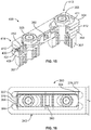
- FIG. 15 illustrates an embodiment that employs alternative working elements 430 which include a spring and ball assembly.
- a cam follower arrangement 400 may include an adjusting element 360 and two working elements 430.
- the cam follower arrangement 400 may be substantially similar to the cam follower arrangements 100, 200, 300 except for the use of the working elements 430.
- the working elements 430 act to absorb energy and reduce noise generated when the first and second holding elements 304, 354 move into contact with the walls of the openings the housing. Unlike the working elements 312, 362, however, the working elements 430 may have a longer life due to the use of the spring and ball assembly.
- the working elements 430 may each include a ball 431 and a spring 412 and, like the working elements 312, 362, may be located at the respective ends 413, 414 of the first and second holding elements 304, 354.
- the first and second working elements 430 each include an enclosure that is sized to receive the ball 431 and the spring 412.
- the spring 412 engages the ball 431 and biases the ball 431 from the ends 413, 414.
- the size of the working element 430 may vary, and the ball 431 and spring 412 of the working elements 430 may include any suitable shape and dimensions.
- the working elements 430 may be about 0.24 inches diameter and about 0.39 inches long. In some instances, it may be possible to eliminate the working element 430.
- the enclosure of the working element 430 may be formed as a urethane cylindrical plug.
- cam follower arrangements may employ two adjusting elements only. Each of the two adjusting elements may be located at the ends of the first and second holding elements 304, 354 such that there is no adjusting element centrally located in the cam follower arrangement.
- a cam follower arrangement may have only one adjusting element that is located at an end of the first or second holding element 304, 354.
- the cam follower arrangement may have two adjusting elements where the first adjusting element is located at an end of the cam follower arrangement and the second adjusting element is centrally located in the cam follower arrangement.
- the term “coupled” means the joining of two members directly or indirectly to one another. Such joining may be stationary or moveable in nature. Such joining may be achieved with the two members or the two members and any additional intermediate members being integrally formed as a single unitary body with one another or with the two members or the two members and any additional intermediate members being attached to one another. Such joining may be permanent in nature or may be removable or releasable in nature.
- cam follower arrangement or components thereof as shown in the various exemplary embodiments are illustrative only. Although only a few embodiments have been described in detail in this disclosure, those skilled in the art who review this disclosure will readily appreciate that many modifications are possible (e.g., variations in sizes, dimensions, structures, shapes and proportions of the various elements, values of parameters, mounting arrangements, use of materials, colors, orientations, etc.) without materially departing from the novel teachings and advantages of the subject matter disclosed. For example, elements shown as integrally formed may be constructed of multiple parts or elements, the position of elements may be reversed or otherwise varied, and the nature or number of discrete elements or positions may be altered or varied.
Landscapes
- Engineering & Computer Science (AREA)
- General Engineering & Computer Science (AREA)
- Mechanical Engineering (AREA)
- Transmission Devices (AREA)
- Gears, Cams (AREA)
Priority Applications (2)
| Application Number | Priority Date | Filing Date | Title |
|---|---|---|---|
| PL13711529T PL2825333T3 (pl) | 2012-03-08 | 2013-03-08 | Układ popychacza krzywkowego |
| EP20208720.1A EP3808471A1 (en) | 2012-03-08 | 2013-03-08 | Cam follower arrangement |
Applications Claiming Priority (2)
| Application Number | Priority Date | Filing Date | Title |
|---|---|---|---|
| US201261608316P | 2012-03-08 | 2012-03-08 | |
| PCT/US2013/030031 WO2013134727A1 (en) | 2012-03-08 | 2013-03-08 | Cam follower arrangement |
Related Child Applications (2)
| Application Number | Title | Priority Date | Filing Date |
|---|---|---|---|
| EP20208720.1A Division EP3808471A1 (en) | 2012-03-08 | 2013-03-08 | Cam follower arrangement |
| EP20208720.1A Division-Into EP3808471A1 (en) | 2012-03-08 | 2013-03-08 | Cam follower arrangement |
Publications (2)
| Publication Number | Publication Date |
|---|---|
| EP2825333A1 EP2825333A1 (en) | 2015-01-21 |
| EP2825333B1 true EP2825333B1 (en) | 2020-12-30 |
Family
ID=47915357
Family Applications (2)
| Application Number | Title | Priority Date | Filing Date |
|---|---|---|---|
| EP13711529.1A Active EP2825333B1 (en) | 2012-03-08 | 2013-03-08 | Cam follower arrangement |
| EP20208720.1A Pending EP3808471A1 (en) | 2012-03-08 | 2013-03-08 | Cam follower arrangement |
Family Applications After (1)
| Application Number | Title | Priority Date | Filing Date |
|---|---|---|---|
| EP20208720.1A Pending EP3808471A1 (en) | 2012-03-08 | 2013-03-08 | Cam follower arrangement |
Country Status (9)
| Country | Link |
|---|---|
| US (1) | US9182026B2 (enExample) |
| EP (2) | EP2825333B1 (enExample) |
| JP (1) | JP2015518546A (enExample) |
| KR (1) | KR102124615B1 (enExample) |
| CN (1) | CN104271283B (enExample) |
| AU (1) | AU2013229771B2 (enExample) |
| ES (1) | ES2861307T3 (enExample) |
| PL (1) | PL2825333T3 (enExample) |
| WO (1) | WO2013134727A1 (enExample) |
Families Citing this family (10)
| Publication number | Priority date | Publication date | Assignee | Title |
|---|---|---|---|---|
| JP7331017B2 (ja) | 2018-05-11 | 2023-08-22 | ストール マシーナリ カンパニー,エルエルシー | 駆動アセンブリ |
| US11117180B2 (en) | 2018-05-11 | 2021-09-14 | Stolle Machinery Company, Llc | Quick change tooling assembly |
| US11208271B2 (en) | 2018-05-11 | 2021-12-28 | Stolle Machinery Company, Llc | Quick change transfer assembly |
| JP7312196B2 (ja) | 2018-05-11 | 2023-07-20 | ストール マシーナリ カンパニー,エルエルシー | 回転マニホールド |
| US11534817B2 (en) | 2018-05-11 | 2022-12-27 | Stolle Machinery Company, Llc | Infeed assembly full inspection assembly |
| CN115673132B (zh) | 2018-05-11 | 2026-04-17 | 斯多里机械有限责任公司 | 成型站和缩颈机 |
| EP3790821B1 (en) | 2018-05-11 | 2025-04-02 | Stolle Machinery Company, LLC | Infeed assembly quick change features |
| US11420242B2 (en) | 2019-08-16 | 2022-08-23 | Stolle Machinery Company, Llc | Reformer assembly |
| US11440078B2 (en) * | 2020-09-15 | 2022-09-13 | Stolle Machinery Company, Llc | Drive assembly |
| US20250269420A1 (en) * | 2024-02-26 | 2025-08-28 | Stolle Machinery Company, Llc | Diagnostic and monitoring system for a die necking machine |
Family Cites Families (21)
| Publication number | Priority date | Publication date | Assignee | Title |
|---|---|---|---|---|
| DE2720129A1 (de) | 1977-05-05 | 1978-11-09 | Heye Hermann Fa | Verfahren und maschine zur herstellung von hohlgegenstaenden mit mehrfachformen |
| MY106679A (en) * | 1989-02-22 | 1995-07-31 | Mitsubishi Materials Corp | Apparatus and method for crimping end of can body |
| US5373934A (en) | 1993-12-10 | 1994-12-20 | Aluminum Company Of America | Bottle-gripping insert element |
| DE4411516B4 (de) * | 1994-04-02 | 2005-12-22 | Carl Zeiss Ag | Spielfreies Kurvengetriebe |
| US5676006A (en) | 1995-03-08 | 1997-10-14 | Delaware Capital Formation, Inc. | Preloaded-cam follower ram assembly for reshaping containers |
| JP3402988B2 (ja) * | 1997-01-31 | 2003-05-06 | 三洋電機株式会社 | 電子部品装着装置の上下動カム機構 |
| US5957655A (en) | 1998-09-10 | 1999-09-28 | Polytype America Corporation | Lid infeed system using a vacuum |
| FR2802191B1 (fr) * | 1999-12-13 | 2002-03-01 | Sidel Sa | Dispositif de convoyage d'entites discretes comportant un bras de transfert perfectionne et installation de soufflage de recipients munie d'un tel dispositif |
| JP2002130427A (ja) * | 2000-10-27 | 2002-05-09 | Zuiko Corp | カム装置 |
| US6694843B2 (en) * | 2001-11-05 | 2004-02-24 | Intech Corporation | Preloaded shock absorbing bushing and cam follower |
| JP4683459B2 (ja) * | 2004-10-27 | 2011-05-18 | パスカルエンジニアリング株式会社 | カムフォロアの取り付け構造 |
| BE1016493A3 (nl) * | 2005-04-13 | 2006-12-05 | Wiele Michel Van De Nv | Inrichting voor het moduleren van een eerste roterende beweging van een inkomende as naar een tweede, verschillend van de eerste, roterende beweging van een uitgaande as bij textielmachines. |
| ITPR20050051A1 (it) | 2005-09-12 | 2007-03-13 | Lanfranchi Srl | Trasportatore a stella ruotante per bottiglie o contenitori vuoti in plastica. |
| US7497145B2 (en) * | 2005-12-28 | 2009-03-03 | Belvac Production Machinery, Inc. | Preloaded-cam follower arrangement |
| US7530445B2 (en) | 2006-03-31 | 2009-05-12 | Belvac Production Machinery, Inc. | Long stroke slide assemblies |
| US7818987B2 (en) * | 2006-03-31 | 2010-10-26 | Belvac Production Machinery, Inc. | Method and apparatus for trimming a can |
| US7603828B2 (en) * | 2006-04-26 | 2009-10-20 | Alcoa Closure Systems International, Inc. | Track adjustable mounting assemblies and associated methods |
| US8006826B2 (en) | 2008-03-28 | 2011-08-30 | Crown Packagin Technology, Inc. | Star wheel with vacuum capability for retaining conveyed articles |
| US8245551B2 (en) | 2008-04-24 | 2012-08-21 | Crown Packaging Technology, Inc. | Adjustable transfer assembly for container manufacturing process |
| US8627705B2 (en) * | 2009-02-26 | 2014-01-14 | Belvac Production Machinery, Inc. | Self compensating sliding air valve mechanism |
| US8047094B2 (en) * | 2009-02-27 | 2011-11-01 | Ut-Battelle, Llc | Hydraulic involute cam actuator |
-
2013
- 2013-03-08 CN CN201380024333.1A patent/CN104271283B/zh active Active
- 2013-03-08 EP EP13711529.1A patent/EP2825333B1/en active Active
- 2013-03-08 WO PCT/US2013/030031 patent/WO2013134727A1/en not_active Ceased
- 2013-03-08 US US13/791,717 patent/US9182026B2/en active Active
- 2013-03-08 KR KR1020147028112A patent/KR102124615B1/ko active Active
- 2013-03-08 AU AU2013229771A patent/AU2013229771B2/en active Active
- 2013-03-08 EP EP20208720.1A patent/EP3808471A1/en active Pending
- 2013-03-08 PL PL13711529T patent/PL2825333T3/pl unknown
- 2013-03-08 JP JP2014561172A patent/JP2015518546A/ja active Pending
- 2013-03-08 ES ES13711529T patent/ES2861307T3/es active Active
Non-Patent Citations (1)
| Title |
|---|
| None * |
Also Published As
| Publication number | Publication date |
|---|---|
| JP2015518546A (ja) | 2015-07-02 |
| KR102124615B1 (ko) | 2020-06-22 |
| EP3808471A1 (en) | 2021-04-21 |
| CN104271283A (zh) | 2015-01-07 |
| ES2861307T3 (es) | 2021-10-06 |
| AU2013229771A1 (en) | 2014-10-23 |
| US20130233123A1 (en) | 2013-09-12 |
| US9182026B2 (en) | 2015-11-10 |
| WO2013134727A1 (en) | 2013-09-12 |
| EP2825333A1 (en) | 2015-01-21 |
| KR20140132768A (ko) | 2014-11-18 |
| PL2825333T4 (pl) | 2021-11-02 |
| PL2825333T3 (pl) | 2021-11-02 |
| CN104271283B (zh) | 2016-09-14 |
| AU2013229771B2 (en) | 2017-06-15 |
Similar Documents
| Publication | Publication Date | Title |
|---|---|---|
| EP2825333B1 (en) | Cam follower arrangement | |
| US6617733B1 (en) | Magnetic bearing apparatus and vacuum pump having magnetic bearing apparatus | |
| US6694843B2 (en) | Preloaded shock absorbing bushing and cam follower | |
| KR101128719B1 (ko) | 유니버설 캠 슬라이드 | |
| EP1967762B1 (en) | Frictional drive transmission | |
| EP2604875A1 (en) | Linear motion guide device | |
| CN111867792B (zh) | 在钳口引导面与外壳之间包括滑动引导件和滚柱引导件的夹持或夹紧装置 | |
| EP2933511A2 (en) | Machine guideways | |
| KR100742908B1 (ko) | 미끄럼운동장치 | |
| EP4245472A1 (en) | Stopper structure and articulated robot | |
| USRE36005E (en) | Antifriction slide assemblies | |
| US4461518A (en) | Sliding roller bearing | |
| CN102974738A (zh) | 双气缸铆点装置 | |
| US4901833A (en) | Combined roller clutch control car and spring | |
| CN215257389U (zh) | 一种重载导向用滑块机构 | |
| KR100506745B1 (ko) | 직선운동 가이드의 외륜 캐리어 | |
| CN112296727B (zh) | 固刀机构及裁床 | |
| KR200390830Y1 (ko) | 볼 트랜스퍼 | |
| CN112296728A (zh) | 裁刀的旋转驱动装置及裁床 | |
| CA3209228A1 (en) | Honing tool and honing stick | |
| KR200211324Y1 (ko) | 프리 베어링의 구조 | |
| JP2542067Y2 (ja) | 直動転がり案内ユニット | |
| KR20140116825A (ko) | 보강빔을 가지는 롤링 베어링을 위한 스페이서 | |
| KR102003996B1 (ko) | 슬라이딩 커버를 포함한 공작기계 | |
| KR20100005264U (ko) | 다단 미끄럼 구조를 갖는 캠 |
Legal Events
| Date | Code | Title | Description |
|---|---|---|---|
| PUAI | Public reference made under article 153(3) epc to a published international application that has entered the european phase |
Free format text: ORIGINAL CODE: 0009012 |
|
| 17P | Request for examination filed |
Effective date: 20141006 |
|
| AK | Designated contracting states |
Kind code of ref document: A1 Designated state(s): AL AT BE BG CH CY CZ DE DK EE ES FI FR GB GR HR HU IE IS IT LI LT LU LV MC MK MT NL NO PL PT RO RS SE SI SK SM TR |
|
| AX | Request for extension of the european patent |
Extension state: BA ME |
|
| RIN1 | Information on inventor provided before grant (corrected) |
Inventor name: YODER, RANDY, E. Inventor name: BOWLIN, GEOFFREY, R. Inventor name: SHORTRIDGE, JEFFREY, L. |
|
| DAX | Request for extension of the european patent (deleted) | ||
| 17Q | First examination report despatched |
Effective date: 20160215 |
|
| STAA | Information on the status of an ep patent application or granted ep patent |
Free format text: STATUS: EXAMINATION IS IN PROGRESS |
|
| GRAP | Despatch of communication of intention to grant a patent |
Free format text: ORIGINAL CODE: EPIDOSNIGR1 |
|
| STAA | Information on the status of an ep patent application or granted ep patent |
Free format text: STATUS: GRANT OF PATENT IS INTENDED |
|
| INTG | Intention to grant announced |
Effective date: 20200714 |
|
| GRAS | Grant fee paid |
Free format text: ORIGINAL CODE: EPIDOSNIGR3 |
|
| GRAA | (expected) grant |
Free format text: ORIGINAL CODE: 0009210 |
|
| STAA | Information on the status of an ep patent application or granted ep patent |
Free format text: STATUS: THE PATENT HAS BEEN GRANTED |
|
| AK | Designated contracting states |
Kind code of ref document: B1 Designated state(s): AL AT BE BG CH CY CZ DE DK EE ES FI FR GB GR HR HU IE IS IT LI LT LU LV MC MK MT NL NO PL PT RO RS SE SI SK SM TR |
|
| REG | Reference to a national code |
Ref country code: GB Ref legal event code: FG4D |
|
| REG | Reference to a national code |
Ref country code: DE Ref legal event code: R096 Ref document number: 602013074993 Country of ref document: DE |
|
| REG | Reference to a national code |
Ref country code: AT Ref legal event code: REF Ref document number: 1349420 Country of ref document: AT Kind code of ref document: T Effective date: 20210115 |
|
| REG | Reference to a national code |
Ref country code: IE Ref legal event code: FG4D |
|
| REG | Reference to a national code |
Ref country code: NL Ref legal event code: FP |
|
| PG25 | Lapsed in a contracting state [announced via postgrant information from national office to epo] |
Ref country code: RS Free format text: LAPSE BECAUSE OF FAILURE TO SUBMIT A TRANSLATION OF THE DESCRIPTION OR TO PAY THE FEE WITHIN THE PRESCRIBED TIME-LIMIT Effective date: 20201230 Ref country code: FI Free format text: LAPSE BECAUSE OF FAILURE TO SUBMIT A TRANSLATION OF THE DESCRIPTION OR TO PAY THE FEE WITHIN THE PRESCRIBED TIME-LIMIT Effective date: 20201230 Ref country code: NO Free format text: LAPSE BECAUSE OF FAILURE TO SUBMIT A TRANSLATION OF THE DESCRIPTION OR TO PAY THE FEE WITHIN THE PRESCRIBED TIME-LIMIT Effective date: 20210330 Ref country code: GR Free format text: LAPSE BECAUSE OF FAILURE TO SUBMIT A TRANSLATION OF THE DESCRIPTION OR TO PAY THE FEE WITHIN THE PRESCRIBED TIME-LIMIT Effective date: 20210331 |
|
| REG | Reference to a national code |
Ref country code: CH Ref legal event code: NV Representative=s name: DENNEMEYER AG, CH |
|
| PG25 | Lapsed in a contracting state [announced via postgrant information from national office to epo] |
Ref country code: BG Free format text: LAPSE BECAUSE OF FAILURE TO SUBMIT A TRANSLATION OF THE DESCRIPTION OR TO PAY THE FEE WITHIN THE PRESCRIBED TIME-LIMIT Effective date: 20210330 Ref country code: SE Free format text: LAPSE BECAUSE OF FAILURE TO SUBMIT A TRANSLATION OF THE DESCRIPTION OR TO PAY THE FEE WITHIN THE PRESCRIBED TIME-LIMIT Effective date: 20201230 Ref country code: LV Free format text: LAPSE BECAUSE OF FAILURE TO SUBMIT A TRANSLATION OF THE DESCRIPTION OR TO PAY THE FEE WITHIN THE PRESCRIBED TIME-LIMIT Effective date: 20201230 |
|
| PG25 | Lapsed in a contracting state [announced via postgrant information from national office to epo] |
Ref country code: HR Free format text: LAPSE BECAUSE OF FAILURE TO SUBMIT A TRANSLATION OF THE DESCRIPTION OR TO PAY THE FEE WITHIN THE PRESCRIBED TIME-LIMIT Effective date: 20201230 |
|
| REG | Reference to a national code |
Ref country code: LT Ref legal event code: MG9D |
|
| PG25 | Lapsed in a contracting state [announced via postgrant information from national office to epo] |
Ref country code: RO Free format text: LAPSE BECAUSE OF FAILURE TO SUBMIT A TRANSLATION OF THE DESCRIPTION OR TO PAY THE FEE WITHIN THE PRESCRIBED TIME-LIMIT Effective date: 20201230 Ref country code: PT Free format text: LAPSE BECAUSE OF FAILURE TO SUBMIT A TRANSLATION OF THE DESCRIPTION OR TO PAY THE FEE WITHIN THE PRESCRIBED TIME-LIMIT Effective date: 20210430 Ref country code: SK Free format text: LAPSE BECAUSE OF FAILURE TO SUBMIT A TRANSLATION OF THE DESCRIPTION OR TO PAY THE FEE WITHIN THE PRESCRIBED TIME-LIMIT Effective date: 20201230 Ref country code: LT Free format text: LAPSE BECAUSE OF FAILURE TO SUBMIT A TRANSLATION OF THE DESCRIPTION OR TO PAY THE FEE WITHIN THE PRESCRIBED TIME-LIMIT Effective date: 20201230 Ref country code: EE Free format text: LAPSE BECAUSE OF FAILURE TO SUBMIT A TRANSLATION OF THE DESCRIPTION OR TO PAY THE FEE WITHIN THE PRESCRIBED TIME-LIMIT Effective date: 20201230 |
|
| REG | Reference to a national code |
Ref country code: AT Ref legal event code: UEP Ref document number: 1349420 Country of ref document: AT Kind code of ref document: T Effective date: 20201230 |
|
| PG25 | Lapsed in a contracting state [announced via postgrant information from national office to epo] |
Ref country code: IS Free format text: LAPSE BECAUSE OF FAILURE TO SUBMIT A TRANSLATION OF THE DESCRIPTION OR TO PAY THE FEE WITHIN THE PRESCRIBED TIME-LIMIT Effective date: 20210430 |
|
| REG | Reference to a national code |
Ref country code: DE Ref legal event code: R097 Ref document number: 602013074993 Country of ref document: DE |
|
| REG | Reference to a national code |
Ref country code: ES Ref legal event code: FG2A Ref document number: 2861307 Country of ref document: ES Kind code of ref document: T3 Effective date: 20211006 |
|
| PG25 | Lapsed in a contracting state [announced via postgrant information from national office to epo] |
Ref country code: AL Free format text: LAPSE BECAUSE OF FAILURE TO SUBMIT A TRANSLATION OF THE DESCRIPTION OR TO PAY THE FEE WITHIN THE PRESCRIBED TIME-LIMIT Effective date: 20201230 Ref country code: MC Free format text: LAPSE BECAUSE OF FAILURE TO SUBMIT A TRANSLATION OF THE DESCRIPTION OR TO PAY THE FEE WITHIN THE PRESCRIBED TIME-LIMIT Effective date: 20201230 |
|
| PLBE | No opposition filed within time limit |
Free format text: ORIGINAL CODE: 0009261 |
|
| STAA | Information on the status of an ep patent application or granted ep patent |
Free format text: STATUS: NO OPPOSITION FILED WITHIN TIME LIMIT |
|
| PG25 | Lapsed in a contracting state [announced via postgrant information from national office to epo] |
Ref country code: DK Free format text: LAPSE BECAUSE OF FAILURE TO SUBMIT A TRANSLATION OF THE DESCRIPTION OR TO PAY THE FEE WITHIN THE PRESCRIBED TIME-LIMIT Effective date: 20201230 |
|
| 26N | No opposition filed |
Effective date: 20211001 |
|
| REG | Reference to a national code |
Ref country code: BE Ref legal event code: MM Effective date: 20210331 |
|
| PG25 | Lapsed in a contracting state [announced via postgrant information from national office to epo] |
Ref country code: LU Free format text: LAPSE BECAUSE OF NON-PAYMENT OF DUE FEES Effective date: 20210308 Ref country code: IE Free format text: LAPSE BECAUSE OF NON-PAYMENT OF DUE FEES Effective date: 20210308 |
|
| PG25 | Lapsed in a contracting state [announced via postgrant information from national office to epo] |
Ref country code: SI Free format text: LAPSE BECAUSE OF FAILURE TO SUBMIT A TRANSLATION OF THE DESCRIPTION OR TO PAY THE FEE WITHIN THE PRESCRIBED TIME-LIMIT Effective date: 20201230 |
|
| PG25 | Lapsed in a contracting state [announced via postgrant information from national office to epo] |
Ref country code: IS Free format text: LAPSE BECAUSE OF FAILURE TO SUBMIT A TRANSLATION OF THE DESCRIPTION OR TO PAY THE FEE WITHIN THE PRESCRIBED TIME-LIMIT Effective date: 20210430 |
|
| PG25 | Lapsed in a contracting state [announced via postgrant information from national office to epo] |
Ref country code: BE Free format text: LAPSE BECAUSE OF NON-PAYMENT OF DUE FEES Effective date: 20210331 |
|
| PG25 | Lapsed in a contracting state [announced via postgrant information from national office to epo] |
Ref country code: HU Free format text: LAPSE BECAUSE OF FAILURE TO SUBMIT A TRANSLATION OF THE DESCRIPTION OR TO PAY THE FEE WITHIN THE PRESCRIBED TIME-LIMIT; INVALID AB INITIO Effective date: 20130308 |
|
| PG25 | Lapsed in a contracting state [announced via postgrant information from national office to epo] |
Ref country code: CY Free format text: LAPSE BECAUSE OF FAILURE TO SUBMIT A TRANSLATION OF THE DESCRIPTION OR TO PAY THE FEE WITHIN THE PRESCRIBED TIME-LIMIT Effective date: 20201230 |
|
| PG25 | Lapsed in a contracting state [announced via postgrant information from national office to epo] |
Ref country code: SM Free format text: LAPSE BECAUSE OF FAILURE TO SUBMIT A TRANSLATION OF THE DESCRIPTION OR TO PAY THE FEE WITHIN THE PRESCRIBED TIME-LIMIT Effective date: 20201230 |
|
| PG25 | Lapsed in a contracting state [announced via postgrant information from national office to epo] |
Ref country code: MK Free format text: LAPSE BECAUSE OF FAILURE TO SUBMIT A TRANSLATION OF THE DESCRIPTION OR TO PAY THE FEE WITHIN THE PRESCRIBED TIME-LIMIT Effective date: 20201230 |
|
| PG25 | Lapsed in a contracting state [announced via postgrant information from national office to epo] |
Ref country code: MT Free format text: LAPSE BECAUSE OF FAILURE TO SUBMIT A TRANSLATION OF THE DESCRIPTION OR TO PAY THE FEE WITHIN THE PRESCRIBED TIME-LIMIT Effective date: 20201230 |
|
| P01 | Opt-out of the competence of the unified patent court (upc) registered |
Free format text: CASE NUMBER: UPC_APP_328530/2023 Effective date: 20230524 |
|
| PGFP | Annual fee paid to national office [announced via postgrant information from national office to epo] |
Ref country code: ES Payment date: 20250429 Year of fee payment: 13 |
|
| PGFP | Annual fee paid to national office [announced via postgrant information from national office to epo] |
Ref country code: CH Payment date: 20250401 Year of fee payment: 13 |
|
| PG25 | Lapsed in a contracting state [announced via postgrant information from national office to epo] |
Ref country code: TR Free format text: LAPSE BECAUSE OF FAILURE TO SUBMIT A TRANSLATION OF THE DESCRIPTION OR TO PAY THE FEE WITHIN THE PRESCRIBED TIME-LIMIT Effective date: 20201230 |
|
| REG | Reference to a national code |
Ref country code: CH Ref legal event code: U11 Free format text: ST27 STATUS EVENT CODE: U-0-0-U10-U11 (AS PROVIDED BY THE NATIONAL OFFICE) Effective date: 20260401 |
|
| PGFP | Annual fee paid to national office [announced via postgrant information from national office to epo] |
Ref country code: GB Payment date: 20260324 Year of fee payment: 14 |
|
| PGFP | Annual fee paid to national office [announced via postgrant information from national office to epo] |
Ref country code: DE Payment date: 20260319 Year of fee payment: 14 |
|
| PGFP | Annual fee paid to national office [announced via postgrant information from national office to epo] |
Ref country code: AT Payment date: 20260320 Year of fee payment: 14 |
|
| PGFP | Annual fee paid to national office [announced via postgrant information from national office to epo] |
Ref country code: IT Payment date: 20260324 Year of fee payment: 14 |
|
| PGFP | Annual fee paid to national office [announced via postgrant information from national office to epo] |
Ref country code: NL Payment date: 20260319 Year of fee payment: 14 |
|
| PGFP | Annual fee paid to national office [announced via postgrant information from national office to epo] |
Ref country code: FR Payment date: 20260320 Year of fee payment: 14 |
|
| PGFP | Annual fee paid to national office [announced via postgrant information from national office to epo] |
Ref country code: CZ Payment date: 20260303 Year of fee payment: 14 |
|
| PGFP | Annual fee paid to national office [announced via postgrant information from national office to epo] |
Ref country code: PL Payment date: 20260227 Year of fee payment: 14 |