EP2824264B1 - Beschlag für ein Fenster, eine Tür oder dergleichen mit einem kipp- und schiebbaren Flügel - Google Patents
Beschlag für ein Fenster, eine Tür oder dergleichen mit einem kipp- und schiebbaren Flügel Download PDFInfo
- Publication number
- EP2824264B1 EP2824264B1 EP13175461.6A EP13175461A EP2824264B1 EP 2824264 B1 EP2824264 B1 EP 2824264B1 EP 13175461 A EP13175461 A EP 13175461A EP 2824264 B1 EP2824264 B1 EP 2824264B1
- Authority
- EP
- European Patent Office
- Prior art keywords
- control
- fitting
- sash
- control pin
- actuating element
- Prior art date
- Legal status (The legal status is an assumption and is not a legal conclusion. Google has not performed a legal analysis and makes no representation as to the accuracy of the status listed.)
- Active
Links
Images


Classifications
-
- E—FIXED CONSTRUCTIONS
- E05—LOCKS; KEYS; WINDOW OR DOOR FITTINGS; SAFES
- E05D—HINGES OR SUSPENSION DEVICES FOR DOORS, WINDOWS OR WINGS
- E05D15/00—Suspension arrangements for wings
- E05D15/06—Suspension arrangements for wings for wings sliding horizontally more or less in their own plane
- E05D15/10—Suspension arrangements for wings for wings sliding horizontally more or less in their own plane movable out of one plane into a second parallel plane
- E05D15/1005—Suspension arrangements for wings for wings sliding horizontally more or less in their own plane movable out of one plane into a second parallel plane the wing being supported on arms movable in horizontal planes
- E05D15/1013—Suspension arrangements for wings for wings sliding horizontally more or less in their own plane movable out of one plane into a second parallel plane the wing being supported on arms movable in horizontal planes specially adapted for windows
- E05D15/1015—Suspension arrangements for wings for wings sliding horizontally more or less in their own plane movable out of one plane into a second parallel plane the wing being supported on arms movable in horizontal planes specially adapted for windows with an intermediate tilt position
-
- E—FIXED CONSTRUCTIONS
- E05—LOCKS; KEYS; WINDOW OR DOOR FITTINGS; SAFES
- E05Y—INDEXING SCHEME ASSOCIATED WITH SUBCLASSES E05D AND E05F, RELATING TO CONSTRUCTION ELEMENTS, ELECTRIC CONTROL, POWER SUPPLY, POWER SIGNAL OR TRANSMISSION, USER INTERFACES, MOUNTING OR COUPLING, DETAILS, ACCESSORIES, AUXILIARY OPERATIONS NOT OTHERWISE PROVIDED FOR, APPLICATION THEREOF
- E05Y2900/00—Application of doors, windows, wings or fittings thereof
- E05Y2900/10—Application of doors, windows, wings or fittings thereof for buildings or parts thereof
- E05Y2900/13—Type of wing
- E05Y2900/148—Windows
Definitions
- the invention relates to a fitting for a window, a door or the like with a tiltable and sliding sash, wherein a stay rod of the fitting can be connected at one end at least indirectly to the sash and at the other end at least indirectly to a glider and/or carriage, and the fitting comprises a control part which has a control contour in or on which a control pin of the stay rod is guided.
- Such a fitting is, for example, from the EP 1 959 080 A2
- This known fitting is designed to park a sash from a closed position, in which the sash rests against the frame, parallel to the main plane of the frame and then move it. When the sash is parked, it undergoes a pivoting movement whose radius is determined by the stay. Thus, the fitting does not move the sash perpendicular to the main plane. of the frame, but rather in an arcuate position. The arcuate position requires that the sash is offset from the frame in the stowed position. Tilting the sash, in which the sash is pivoted away from the frame on one side and remains attached to the frame on the opposite side, is therefore not possible with the conventional hardware.
- the object of the invention is therefore to provide a fitting that allows both sliding and tilting of a sash of a window, door, or the like around a horizontal pivot axis.
- the design of the fitting according to the invention enables both tilting of the sash - namely when the control pin is moved in the first control section or on the first control section - and displacement of the sash - namely when the control pin is moved in the second control section or on the second control section.
- the control part also has a bolt which, in a blocking position, limits or prevents the movement of the control pin along the control contour.
- the bolt can be moved into a release position by an actuating element of the fitting which is at least indirectly rotatably connected to the stay link, in which position it does not limit or prevent the movement of the control pin.
- the bolt serves as a stop against which the control pin moves when the sash is closed if the sash has been moved parallel to the frame and is now to be closed, i.e. if the sash is moved from a sliding position to a closed position.
- the bolt acting as a stop enables a controlled movement from the sliding position to the closed position.
- the control pin of the stay link can move more freely within the control contour.
- the stay link thus receives the necessary Clearance to allow the sash to tilt and open.
- the fitting thus enables both a controlled movement of the sash from the closed position to the tilt and open position and back to the closed position, as well as a controlled movement from the closed position to the sliding position and back to the closed position.
- the fitting can be provided for at least indirectly connecting any side of a sash to the frame.
- the fitting according to the invention is provided on the top side, and a conventional fitting, which enables a pure parking and sliding movement of the sash, is provided on the underside of the sash.
- the conventional fitting is preferably connected to two carriages. This allows the sash to be moved from the closed position to the sliding position and to be moved parallel to the main frame plane.
- the upper fitting can have carriages or gliders. The sash can be tilted away from the frame at the top side from the closed position.
- the latch In the blocking position, the latch is arranged between the first control section and the second control section. In the blocking position, the latch can thus prevent movement of the control pin from the second control section into the first control section. In contrast, when the latch is in the release position, the control pin can move from the second control section into the first control section.
- the actuating element is preferably formed or arranged on a slider and/or carriage. This allows the fitting to be the sliding position parallel to the main plane of the frame.
- the actuating element can be designed, at least in sections, in the form of a plate-shaped cover of the control part in order to achieve a space-saving fitting.
- the latch can be moved from the blocking position to the release position by the actuating element against the force of a return element. This causes the latch to automatically return to the blocking position after actuation by the return element. In this case, no means for returning the latch to the blocking position need to be provided on the actuating element, thus simplifying the design of the actuating element.
- the fitting can be designed to be particularly simple if the bolt is attached to a control part body of the control part via the return element.
- the bolt is designed in the form of a threshold, which has a bevel and/or curvature on a first side that interacts with the control pin.
- the bolt can be designed as a stop for the control pin on a second side opposite the first side. If the control pin is moved against the first side during a closing movement from the tilt-open position, it displaces the bolt or pushes it away. If, however, the control pin is moved against the second side of the bolt during a closing movement from the sliding position, it cannot displace the bolt.
- the second side is preferably designed in the form of a wall.
- Such a design of the bolt ensures that the control pin can always pass the bolt in a first direction - namely, toward the first side of the bolt - while in the second direction - namely, toward the second side of the bolt - it can only pass the bolt when the actuating element releases the bolt.
- the bolt is preferably arranged in the fitting so that the control pin is always The fitting can move from the tilt-open position to the closed position, but only when released by the actuating element. This ensures that the sash can be moved in a controlled manner from the sliding position to the closed position, as well as from the tilt-open position to the closed position.
- the control part can have a locking element for reversibly and releasably fixing the position of the control pin in the tilt-open position.
- the locking element is preferably designed in the form of a spring. The locking element secures the tilt-open position of the fitting by holding the control pin in a defined position. The tilted sash cannot thus be moved into the closed position by a draft, but must be deliberately closed against the resistance of the locking element.
- the actuating element has a guide contour in or on which the control pin is guided.
- the actuating element can thus be moved relative to the control pin in a simple and defined manner.
- the scissor stay preferably has a projection arm for tilting the sash and a control arm rotatably mounted on the projection arm.
- the projection arm at least indirectly establishes the connection between the sash and the frame, while the control arm serves to limit the movement of the projection arm.
- the extension arm is rotatably connected to the actuating element.
- the actuating element can thus be directly
- the opening scissors can be controlled. This significantly simplifies the design of the fitting.
- control pin is formed or arranged on the control arm.
- control pin can also be formed or arranged on the extension arm, and the control arm can be rotatably coupled to the actuating element.
- the invention further relates to a window, a door or the like with a fitting as described above.
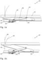
- Fig. 1a shows a fitting 10 according to the invention for connecting a sash of a window, a door or the like to a frame of this window, door, or the like.
- the fitting 10 has a sash part 12 and a control part (control block) 14.
- the sash part 12 is part of a sash or at least attachable to a sash.
- the control part 14 is part of a frame or at least attachable to a frame.
- the wing part 12 can be attached directly and immovably to a wing and the control part 14 can be attached directly and immovably to a frame.
- a stay scissor 16 To control the movement of the sash from a closed position into a parallel sliding position or a tilt-open position, a stay scissor 16 is provided.
- the stay scissor 16 comprises a stay arm 18 and a control arm 20.
- the control arm 20 is rotatably mounted on the stay arm 18 at one end via a first bearing 22.
- the control arm 20 has a control pin 24.
- the control pin 24 is guided in a control contour 26 in the form of a control groove of the control part 14.
- Fig. 1b shows the fitting 10 when the sash is opened, i.e., when the sash part 12 is set aside from the control part 14.
- the sash or the sash part 12 can be spaced apart from the frame or the control part 14 along two "paths."
- a first path 28 runs perpendicular to the main frame plane of the window, door, or the like. If the sash part 12 is set aside along the first path 28, the sash can be brought into the tilt-open position.
- a second path 30 runs in an arc. This arc is described when the sash or the sash part 12 is set aside in a parallel, set-back position, from which the sash can be moved. When the sash is moved, the control pin 24 leaves the control part 14.
- Whether the sash or sash part 12 follows the first path 28 or the second path 30 depends on the switching position of a connecting rod fitting (not shown). If the connecting rod fitting is in the "sliding opening" switching position, the sash can be parked parallel, i.e., it takes the second path 30. If the connecting rod fitting is in the "tilt opening” switching position, the sash is held against the fixed frame at the bottom, and the sash can take the first path 28 at the top, where the fitting 10 is located.
- the first path 28 and the second path 30 are in a first section 32 which the wing part 12 defines between the Fig. 1a and the Fig. 1b shown position, are approximately congruent. Only in the further course of movement of the wing part 12 do the paths 28 and 30 differ significantly. This is shown in Fig. 1c and Fig. 1d shown.
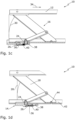
- Fig. 1c shows the fitting 10 in the sliding position.
- the sash part 12 has been moved along the second path 30.
- the user can pull the sash or sash part 12 in the direction of a first arrow 34.
- the control pin 24 is thereby pulled out of the control contour 26.
- the control pin 24 In the Fig. 1c In the sliding position shown, the control pin 24 cannot be moved into a first control section 36 of the control contour 26. The movement of the control pin 24 is rather limited to a second control section 38 of the control contour 26. The control pin 24 is prevented from moving from the second control section 38 into the first control section 36 by a bolt 40. In other words, the bolt 40 serves as a stop for the control pin 24. This function as a stop plays an important role when closing the sash from the sliding position into the closed position, that is to say when the sash part 12 is moved in the opposite direction of the first arrow 34 from the Fig. 1c shown position into the Fig. 1a shown position. During this movement, the control pin 24 is inserted into the control contour 26 and then strikes the bolt 40, so that the sash part 12 is forced by the extension scissors 16 into a controlled, arcuate closing movement along the second path 30.
- Fig. 1d shows the fitting 10 in the tilt-open position.
- the control pin 24 requires appropriate play in the control part 14:
- the control pin 24 must be movable from the second control section 38 into the first control section 36 of the control contour 26.
- the latch 40 must release the movement of the control pin 24. This release is effected by an actuating element 42.
- the actuating element 42 is moved for this purpose by the extension arm 18, which is rotatably connected to the actuating element 42 via a second bearing 44.
- the design of the control part 14 and the actuating element 42 for actuating the latch 40 is explained below. Fig. 2a, 2b and Fig. 3 visible.
- Fig. 2a shows the control unit 14. From Fig. 2a It can be seen that the latch 40 is arranged on a control part body 47 of the control part 14 via a return element 46.
- the return element 46 is essentially designed in the form of a leaf spring and presses the latch 40 against the control part body 47.
- the return element 46 can also be designed in another form, in particular in the form of a cylindrical compression spring.
- the latch 40 divides the control contour 26 into the first Control section 36, in which the control pin 24 (see Fig. 1a ) is moved during the transition from a closed position to a tilt-open position, and the second control section 38, in which the control pin 24 is moved during the transition from a closed position to a sliding position.
- the first control section 36 is angled to the second control section 38, wherein the first control section 36 extends parallel to the longitudinal direction of the control part 14 or parallel to the circumferential direction of the fold, and the second control section 38 is aligned transversely thereto.
- the bolt 40 of the control part 14 is designed in the form of a threshold, which has a first side 48 and a second side 50.
- the first side 48 is designed in the form of a slope
- the second side 50 in the form of a vertical stop. If the control pin 24 (see Fig. 1d ) in the direction of a second arrow 52 towards the first side 48, it displaces the threshold 40 downwards, i.e. in the direction of a third arrow 54. If, on the other hand, the control pin 24 is moved in the direction of a fourth arrow 56 towards the second side 50, the control pin cannot displace the bolt 40.
- a movement in the direction of the second arrow 52 corresponds to a movement from the tilt opening position (see Fig. 1d ) into the closed position (see Fig. 1a ), while a movement in the direction of the fourth arrow 56 corresponds to a movement from the sliding position (see Fig. 1c ) into the closed position (see Fig. 1a ).
- the described design of the latch 40 thus ensures that the fitting 10 can always be moved from the tilt-open position to the closed position.
- a controlled pivoting of the sash from the sliding position to the closed position is enabled, since the control pin 24 cannot itself displace the latch 40 in the direction of the fourth arrow 56.
- the control pin 24 In the tilt opening position (see Fig. 1d ), the control pin 24 is held in place by a reversibly releasable locking element 58 in the form of a leaf spring. The wing cannot therefore be moved from the tilted open position to the closed position by a draft of air alone (see Fig. 1a ) are transferred.
- Fig. 3 shows a section of this actuating element 42.
- the actuating element 42 is formed in one piece and has a guide contour 60 in which the control pin 24 is guided (see Fig. 1b ).
- the Fig. 3 The front section of the actuating element 42 shown is designed as a slider, so that the wing (see Fig. 1a ) can be moved parallel to the frame.
- the fitting 10 can be connected directly or indirectly, i.e. at least indirectly, to a slider for sliding the sash.
- the actuating element 42 has an actuating projection 62.
- Another similarly designed actuating projection is arranged on the opposite side, Fig. 3 non-visible side of the actuating element 42.
- the actuating projection 62 can - as an alternative to the one-piece embodiment shown - be arranged in the form of an additional component on the actuating element 42 or on the slider and/or carriage.
- the actuating projection 62 is to operate the bolt 40 (see Fig. 2b ) as can be seen from the following Fig. 4a-4d is evident.
- Fig. 4a shows the fitting 10 in the closed position according to Fig. 1a
- the bolt 40 is pressed by the return element 46 against the control part body 47.
- the bolt 40 forms a stop which is insurmountable for the control pin 24 (see also Fig. 1a ).
- the bolt 40 is in a blocking position.
- Fig. 4b shows the fitting 10 in the partially opened position according to Fig. 1b .
- the actuating element 42 has been displaced by the extension scissors 16 in the direction of a fifth arrow 64.
- the actuating projection 62 displaces the bolt 40 against the resistance of the return element 46 and thereby allows the control pin 24 (see also Fig. 1b ) passing through the bolt 40.
- the bolt 40 is in a release position.
- the bolt 40 and the actuating projection 62 have run-up slopes. This reduces the resistance between the actuating element 42 and the bolt 40.
- the fitting 10 is therefore easy to handle for the user.
- the bolt 40 and/or the actuating projection 62 have a sliding surface to further reduce the resistance.
- Fig. 4c shows the fitting 10 in the sliding position according to Fig. 1c .
- the actuating element 42 has been moved further in the direction of the fifth arrow 64, so that the actuating projection 62 has already passed the bolt 40.
- the control pin 24 can therefore no longer overcome the bolt 40.
- the bolt 40 thus serves as a stop during the transition from the parallel to the frame "Sliding" the sash into the pivoting movement to the final closing position (see Fig. 1a ).
- Fig. 4d shows the fitting 10 in the tilt opening position according to Fig. 1d .
- the actuating element 42 is displaced completely in the direction of the fifth arrow 64, so that the bolt 40 is not actuated by the actuating projection 62.
- the control pin 24 can actuate the bolt 40 (see Fig. 1d ) automatically - as described above - to return to the closed position according to Fig. 1a to get there.
- the invention relates to a fitting for connecting a sash of a window, door, or the like to its frame.
- the fitting enables the sash—depending on the coupling of the sash to the frame by another fitting—to be either tilted or positioned parallel to the main plane of the frame and then moved parallel to the main plane of the frame.
- the fitting has a stay rod, which is guided via a control pin in a control part connectable to the frame.
- a bolt of the control part limits the travel of the control pin during the closing movement of the sash from a position displaced parallel to the main plane of the frame. This enables a controlled and defined arcuate closing movement.
- an actuating element connected to the stay rod enables the displacement of the bolt when the sash is to be tilted, in order to allow greater movement of the control pin and thus a straight pivoting of the sash into a tilt-open position.
- the actuating element is preferably designed as a slider for moving the wing or is connected to a slider for moving the wing.
Landscapes
- Engineering & Computer Science (AREA)
- Mechanical Engineering (AREA)
- Power-Operated Mechanisms For Wings (AREA)
- Wing Frames And Configurations (AREA)
- Extensible Doors And Revolving Doors (AREA)
Description
- Die Erfindung betrifft einen Beschlag für ein Fenster, eine Tür oder dergleichen mit einem kipp- und schiebbaren Flügel, wobei eine Ausstellschere des Beschlags einenends zumindest mittelbar mit dem Flügel und anderenends zumindest mittelbar mit einem Gleiter und/oder Laufwagen verbindbar ist und der Beschlag ein Steuerteil umfasst, das eine Steuerkontur aufweist, in der oder an der ein Steuerzapfen der Ausstellschere geführt ist.
- Ein solcher Beschlag ist beispielsweise aus der
EP 1 959 080 A2 bekannt geworden. Der bekannte Beschlag ist dazu ausgebildet, einen Flügel von einer Schließstellung, in der der Flügel am Rahmen anliegt, parallel zur Hauptebene des Rahmens vom Rahmen abzustellen und dann zu verschieben. Beim Abstellen des Flügels durchläuft dieser eine Schwenkbewegung, deren Radius von der Ausstellschere vorgegeben wird. Der Flügel wird somit durch den Beschlag nicht senkrecht zur Hauptebene des Rahmens, sondern bogenförmig vom Rahmen abgestellt. Das bogenförmige Abstellen bedingt, dass sich der Flügel in der abgestellten Stellung versetzt zum Rahmen befindet. Ein Kippen des Flügels, bei dem der Flügel auf einer Seite vom Rahmen weg geschwenkt wird und auf der gegenüberliegenden Seite am Rahmen verbleibt, ist durch den bekannten Beschlag daher nicht erreichbar. - Aus der
DE 20 2008 004 033 U1 ist weiterhin ein Beschlag für Horizontal-Schiebetüren mit einem Schiebeflügel bekannt geworden. Die Bewegung des Schiebeflügels wird durch ein Steuerelement beeinflusst, wobei der Schiebeflügel nach Entriegelung der Verschlussstellung senkrecht zu seiner Schiebeflügelebene bewegbar und in einer verriegelten Offenstellung längs zweier parallel zueinander liegenden Führungen frei verschiebbar ist. - Es besteht allerdings bereits seit längerer Zeit ein Bedarf nach Flügeln eines Fensters, einer Tür oder dergleichen, die sowohl kippbar als auch verschiebbar sind. Die Aufgabe der Erfindung ist es daher, einen Beschlag bereitzustellen, der sowohl ein Verschieben als auch ein Verkippen eines Flügels eines Fensters, einer Tür oder dergleichen um eine horizontale Schwenkachse ermöglicht.
- Diese Aufgabe wird erfindungsgemäß durch einen Beschlag für ein Fenster, eine Tür oder dergleichen mit einem kipp- und schiebbaren Flügel gelöst, wobei eine Ausstellschere des Beschlags einenends zumindest mittelbar mit dem Flügel und anderenends zumindest mittelbar mit einem Gleiter und/oder Laufwagen verbindbar ist und der Beschlag ein Steuerteil umfasst, das eine Steuerkontur aufweist, in der oder an der ein Steuerzapfen der Ausstellschere geführt ist, wobei
- a) die Steuerkontur einen ersten Steuerabschnitt und einen zweiten Steuerabschnitt aufweist und der Steuerzapfen in dem oder an dem ersten Steuerabschnitt zur Kippöffnung des Flügels und in dem oder an dem zweiten Steuerabschnitt zur Schiebeöffnung des Flügels bewegt wird und
- b) das Steuerteil einen Riegel aufweist, der in einer Blockadestellung die Bewegung des Steuerzapfens entlang der Steuerkontur begrenzt oder verhindert, wobei der Riegel durch ein zumindest mittelbar drehbar mit der Ausstellschere verbundenes Betätigungselement des Beschlages in eine Freigabestellung bewegbar ist, in der er die Bewegung des Steuerzapfens nicht begrenzt oder verhindert, wobei der Riegel in der Blockadestellung zwischen dem ersten Steuerabschnitt und dem zweiten Steuerabschnitt angeordnet ist.
- Die erfindungsgemäße Ausbildung des Beschlages ermöglicht sowohl ein Verkippen des Flügels - nämlich wenn der Steuerzapfen in dem ersten Steuerabschnitt oder an dem ersten Steuerabschnitt bewegt wird - als auch ein Verschieben des Flügels - nämlich wenn der Steuerzapfen in dem zweiten Steuerabschnitt oder an dem zweiten Steuerabschnitt bewegt wird.
- Das Steuerteil weist zusätzlich dazu einen Riegel auf, der in einer Blockadestellung die Bewegung des Steuerzapfens entlang der Steuerkontur begrenzt oder verhindert, wobei der Riegel durch ein zumindest mittelbar drehbar mit der Ausstellschere verbundenes Betätigungselement des Beschlages in eine Freigabestellung bewegbar ist, in der er die Bewegung des Steuerzapfens nicht begrenzt oder verhindert. In der Blockadestellung dient der Riegel als Anschlag, gegen den der Steuerzapfen beim Schließen des Flügels fährt, wenn der Flügel parallel zum Rahmen verschoben war und nun geschlossen werden soll, wenn der Flügel also von einer Schiebestellung in eine Schließstellung bewegt wird. Der als Anschlag dienende Riegel ermöglicht eine kontrollierte Bewegung aus der Schiebestellung in die Schließstellung. Wird der Riegel demgegenüber durch das Betätigungselement in die Freigabestellung freigegeben, kann sich der Steuerzapfen der Ausstellschere freier in der Steuerkontur bewegen. Die Ausstellschere erhält dadurch den nötigen Spielraum, um eine Kippöffnungsbewegung des Flügels zu ermöglichen. Der Beschlag ermöglicht somit sowohl eine kontrollierte Bewegung des Flügels aus der Schließstellung in eine Kippöffnungsstellung und wieder zurück in die Schließstellung als auch eine kontrollierte Bewegung aus der Schließstellung in die Schiebestellung und wieder zurück in die Schließstellung.
- Der Beschlag kann zur zumindest mittelbaren Verbindung einer beliebigen Seite eines Flügels mit dem Rahmen vorgesehen sein. Vorzugsweise ist der erfindungsgemäße Beschlag an der Oberseite und ein konventioneller Beschlag, der eine reine Abstell- und Schiebebewegung des Flügels ermöglicht, an der Unterseite des Flügels vorgesehen. Der konventionelle Beschlag ist dabei vorzugsweise mit zwei Laufwagen verbunden. Hierdurch kann der Flügel von der Schließstellung in die Schiebestellung gebracht und parallel zur Rahmenhauptebene verschoben werden. Der obere Beschlag kann Laufwagen oder Gleiter aufweisen. Der Flügel kann von der Schließstellung an der Oberseite vom Rahmen weggekippt werden.
- Der Riegel ist in der Blockadestellung zwischen dem ersten Steuerabschnitt und dem zweiten Steuerabschnitt angeordnet. In der Blockadestellung kann der Riegel somit eine Bewegung des Steuerzapfens aus dem zweiten Steuerabschnitt in den ersten Steuerabschnitt unterbinden. Demgegenüber kann sich der Steuerzapfen, wenn sich der Riegel in der Freigabestellung befindet, von dem zweiten Steuerabschnitt in den ersten Steuerabschnitt bewegen.
- Das Betätigungselement ist vorzugsweise an einem Gleiter und/oder Laufwagen ausgebildet oder angeordnet. Hierdurch kann der Beschlag in der Schiebestellung parallel zur Hauptebene des Rahmens verschoben werden.
- Das Betätigungselement kann zumindest abschnittsweise in Form einer plattenförmigen Abdeckung des Steuerteils ausgebildet sein, um einen platzsparenden Beschlag zu erzielen.
- Vorzugsweise ist der Riegel gegen die Kraft eines Rückstellelements durch das Betätigungselement von der Blockadestellung in die Freigabestellung bewegbar. Hierdurch wird der Riegel nach dessen Betätigung durch das Rückstellelement selbständig zurück in die Blockadestellung bewegt. Am Betätigungselement müssen in diesem Fall keine Mittel zur Rückführung des Riegels in die Blockadestellung vorgesehen werden, wodurch die konstruktive Ausbildung des Betätigungselements vereinfacht wird.
- Der Beschlag kann konstruktiv besonders einfach ausgebildet sein, wenn der Riegel über das Rückstellelement an einem Steuerteilkörper des Steuerteils befestigt ist.
- In bevorzugter Ausgestaltung der Erfindung ist der Riegel in Form einer Schwelle ausgebildet, die auf einer ersten Seite eine mit dem Steuerzapfen zusammenwirkende Schräge und/oder Krümmung aufweist. Der Riegel kann auf einer der ersten Seite gegenüberliegenden zweiten Seite als Anschlag für den Steuerzapfen ausgebildet sein. Wird der Steuerzapfen bei einer Schließbewegung aus der Kippöffnungsstellung gegen die erste Seite bewegt, so verdrängt er den Riegel bzw. drückt ihn weg. Wird der Steuerzapfen hingegen bei einer Schließbewegung aus der Schiebestellung gegen die zweite Seite des Riegels bewegt, so kann er den Riegel nicht verdrängen. Die zweite Seite ist dabei vorzugsweise in Form einer Wand ausgebildet. Durch eine solche Ausbildung des Riegels kann sichergestellt werden, dass der Steuerzapfen in eine erste Richtung - nämlich in Richtung gegen die erste Seite des Riegels - den Riegel stets passieren kann, während er in die zweite Richtung - nämlich in Richtung gegen die zweite Seite des Riegels - nur dann den Riegel passieren kann, wenn das Betätigungselement den Riegel freigibt. Der Riegel ist dabei vorzugsweise so in dem Beschlag angeordnet, dass der Steuerzapfen stets eine Bewegung des Beschlages von der Kippöffnungsstellung in die Schließstellung, aber nur bei Freigabe durch das Betätigungselement eine Bewegung des Beschlages von der Schließstellung in die Kippöffnungsstellung ermöglicht. Hierdurch wird erreicht, dass der Flügel sowohl kontrolliert geführt von der Schiebestellung in die Schließstellung bewegbar ist als auch in jedem Fall von der Kippöffnungsstellung in die Schließstellung bewegbar ist.
- Das Steuerteil kann ein Arretierungselement zur reversibel lösbaren Festlegung der Position des Steuerzapfens in der Kippöffnungsstellung aufweisen. Das Arretierungselement ist dabei vorzugsweise in Form einer Feder ausgebildet. Das Arretierungselement sichert die Kippöffnungsstellung des Beschlags durch Halten des Steuerzapfens in einer definierten Position. Der gekippte Flügel kann dadurch nicht durch einen Luftzug in die Schließstellung übergehen, sondern muss willentlich gegen den Widerstand des Arretierungselements geschlossen werden.
- Vorzugsweise weist das Betätigungselement eine Führungskontur auf, in der oder an der der Steuerzapfen geführt ist. Das Betätigungselement kann dadurch auf einfache und definierte Art und Weise relativ zu dem Steuerzapfen bewegt werden.
- Die Ausstellschere weist vorzugsweise einen Ausstellarm zum Abstellen des Flügels und einen am Ausstellarm drehbar angeordneten Steuerarm auf. Der Ausstellarm stellt dabei zumindest mittelbar die Verbindung zwischen Flügel und Rahmen her, während der Steuerarm zur Begrenzung der Bewegung des Ausstellarms dient.
- Vorzugsweise ist der Ausstellarm drehbar mit dem Betätigungselement verbunden. Das Betätigungselement kann dadurch unmittelbar von der Ausstellschere gesteuert werden. Die konstruktive Ausbildung des Beschlages wird dadurch wesentlich vereinfacht.
- Eine bevorzugte Erfindungsbauart zeichnet sich dadurch aus, dass der Steuerzapfen am Steuerarm ausgebildet oder angeordnet ist. Der Steuerzapfen kann demgegenüber auch am Ausstellarm ausgebildet oder angeordnet und der Steuerarm drehbar mit dem Betätigungselement gekoppelt sein.
- Die Erfindung betrifft weiterhin ein Fenster, eine Tür oder dergleichen mit einem zuvor beschriebenen Beschlag.
- Weitere Merkmale und Vorteile der Erfindung ergeben sich aus der nachfolgenden detaillierten Beschreibung eines Ausführungsbeispiels der Erfindung, anhand der Figuren der Zeichnung, die erfindungswesentliche Einzelheiten zeigt, sowie aus den Patentansprüchen.
- Die in der Zeichnung dargestellten Merkmale sind nicht notwendigerweise maßstäblich zu verstehen und derart dargestellt, dass die erfindungsgemäßen Besonderheiten deutlich sichtbar gemacht werden können. Die verschiedenen Merkmale können je einzeln für sich oder zu mehreren in beliebigen Kombinationen bei Varianten der Erfindung innerhalb des in den Ansprüchen definierten Umfangs verwirklicht sein.
- In der schematischen Zeichnung ist ein Ausführungsbeispiel der Erfindung dargestellt und in der nachfolgenden Beschreibung näher erläutert.
- Es zeigen:
- Fig. 1a
- eine teilweise geschnittene perspektivische Ansicht eines Beschlags in der Schließstellung;
- Fig. 1b
- den Beschlag aus
Fig. 1a in teilweise geöffneter Stellung; - Fig. 1c
- den Beschlag aus
Fig. 1b in der Schiebestellung; - Fig. 1d
- den Beschlag aus
Fig. 1b in der Kippöffnungsstellung; - Fig. 2a
- das Steuerteil des Beschlags aus
Fig. 1a-d in einer ersten perspektivischen Ansicht; - Fig. 2b
- das Steuerteil aus
Fig. 2a in einer zweiten perspektivischen Ansicht; - Fig. 3
- das Betätigungselement des Beschlags aus
Fig. 1a-d in einer perspektivischen Ansicht; - Fig. 4a
- eine Seitenansicht des Beschlags gemäß
Fig. 1a ; - Fig. 4b
- eine Seitenansicht des Beschlags gemäß
Fig. 1b ; - Fig. 4c
- eine Seitenansicht des Beschlags gemäß
Fig. 1c ; und - Fig. 4d
- eine Seitenansicht des Beschlags gemäß
Fig. 1d . -
Fig. 1a zeigt einen erfindungsgemäßen Beschlag 10 zur Verbindung eines Flügels eines Fensters, einer Tür oder dergleichen mit einem Rahmen dieses Fensters, der Tür oder dergleichen. Der Beschlag 10 weist ein Flügelteil 12 und ein Steuerteil (Steuerklotz) 14 auf. Das Flügelteil 12 ist Teil eines Flügels oder zumindest an einem Flügel befestigbar. Das Steuerteil 14 ist Teil eines Rahmens oder zumindest an einem Rahmen befestigbar. Im inFig. 1a dargestellten Fall ist das Flügelteil 12 unmittelbar und unbeweglich an einem Flügel und das Steuerteil 14 unmittelbar und unbeweglich an einem Rahmen befestigbar. - Um die Bewegung des Flügels von einer Schließstellung in eine parallel abgestellte Schiebestellung oder eine Kippöffnungsstellung zu steuern, ist eine Ausstellschere 16 vorgesehen. Die Ausstellschere 16 umfasst einen Ausstellarm 18 und einen Steuerarm 20. Der Steuerarm 20 ist einenends über ein erstes Lager 22 drehbar am Ausstellarm 18 angeordnet. Anderenends weist der Steuerarm 20 einen Steuerzapfen 24 auf. Der Steuerzapfen 24 ist in einer Steuerkontur 26 in Form einer Steuernut des Steuerteils 14 geführt.
-
Fig. 1b zeigt den Beschlag 10 beim Öffnen des Flügels, das heißt beim Abstellen des Flügelteils 12 vom Steuerteil 14. Der Flügel bzw. das Flügelteil 12 kann auf zwei "Wegen" von dem Rahmen bzw. dem Steuerteil 14 beabstandet werden. Ein erster Weg 28 verläuft senkrecht zur Rahmenhauptebene des Fensters, der Tür oder dergleichen. Wird das Flügelteil 12 entlang des ersten Weges 28 abgestellt, so kann der Flügel in die Kippöffnungsstellung gebracht werden. Ein zweiter Weg 30 verläuft in einem Bogen. Dieser Bogen wird beschrieben, wenn der Flügel bzw. das Flügelteil 12 in eine parallel abgestellte Stellung gebracht werden, aus der heraus der Flügel verschoben werden kann. Beim Verschieben des Flügels verlässt der Steuerzapfen 24 das Steuerteil 14. - Ob der erste Weg 28 oder der zweite Weg 30 von dem Flügel bzw. dem Flügelteil 12 eingeschlagen wird, richtet sich nach der Schaltstellung eines nicht gezeigten Treibstangenbeschlags. Ist der Treibstangenbeschlag in einer Schaltstellung "Schiebeöffnen", kann der Flügel parallel abgestellt werden, das heißt er nimmt den zweiten Weg 30. Ist der Treibstangenbeschlag in der Schaltstellung "Kippöffnen", wird der Flügel unten in Anlage an dem festen Rahmen gehalten und der Flügel kann oben, wo der Beschlag 10 angeordnet ist, den ersten Weg 28 nehmen.
- Der erste Weg 28 und der zweite Weg 30 sind in einem ersten Abschnitt 32, den das Flügelteil 12 zwischen der in
Fig. 1a und der inFig. 1b gezeigten Stellung durchläuft, näherungsweise deckungsgleich. Erst im weiteren Bewegungsverlauf des Flügelteils 12 unterscheiden sich die Wege 28 und 30 signifikant. Dies ist inFig. 1c und Fig. 1d dargestellt. -
Fig. 1c zeigt den Beschlag 10 in der Schiebestellung. Das Flügelteil 12 ist dabei entlang des zweiten Weges 30 bewegt worden. Um den Flügel nun parallel zum Rahmen zu verschieben und das Fenster, die Tür oder dergleichen somit weiter zu öffnen, kann der Benutzer den Flügel bzw. das Flügelteil 12 in Richtung eines ersten Pfeils 34 ziehen. Der Steuerzapfen 24 wird dabei aus der Steuerkontur 26 herausgezogen. - In der in
Fig. 1c gezeigten Schiebestellung kann der Steuerzapfen 24 nicht in einen ersten Steuerabschnitt 36 der Steuerkontur 26 bewegt werden. Die Bewegung des Steuerzapfens 24 ist vielmehr auf einen zweiten Steuerabschnitt 38 der Steuerkontur 26 beschränkt. Der Steuerzapfen 24 wird dabei durch einen Riegel 40 am Verfahren aus dem zweiten Steuerabschnitt 38 in den ersten Steuerabschnitt 36 gehindert. Mit anderen Worten dient der Riegel 40 als Anschlag für den Steuerzapfen 24. Diese Funktion als Anschlag spielt eine wichtige Rolle beim Schließen des Flügels aus der Schiebestellung in die Schließstellung, das heißt beim Bewegen des Flügelteils 12 entgegen der Richtung des ersten Pfeils 34 von der inFig. 1c gezeigten Stellung in die inFig. 1a gezeigte Stellung. Denn bei dieser Bewegung wird der Steuerzapfen 24 in die Steuerkontur 26 eingebracht und schlägt dann gegen den Riegel 40 an, sodass das Flügelteil 12 durch die Ausstellschere 16 zu einer kontrollierten bogenförmigen Schließbewegung entlang des zweiten Weges 30 gezwungen wird. -
Fig. 1d zeigt den Beschlag 10 demgegenüber in der Kippöffnungsstellung. Um das Flügelteil 12 über den ersten Weg 28 in die gezeigte Kippöffnungsstellung zu bewegen, benötigt der Steuerzapfen 24 entsprechenden Spielraum im Steuerteil 14: Der Steuerzapfen 24 muss vom zweiten Steuerabschnitt 38 in den ersten Steuerabschnitt 36 der Steuerkontur 26 bewegbar sein. Hierzu muss der Riegel 40 die Bewegung des Steuerzapfens 24 freigeben. Diese Freigabe erfolgt durch ein Betätigungselement 42. Das Betätigungselement 42 wird hierzu durch den Ausstellarm 18 bewegt, der über ein zweites Lager 44 drehbar mit dem Betätigungselement 42 verbunden ist. Die zur Betätigung des Riegels 40 vorgenommene Ausbildung des Steuerteils 14 und des Betätigungselements 42 ist aus den nachfolgend erläutertenFig. 2a, 2b und Fig. 3 ersichtlich. -
Fig. 2a zeigt das Steuerteil 14. AusFig. 2a wird ersichtlich, dass der Riegel 40 über ein Rückstellelement 46 an einem Steuerteilkörper 47 des Steuerteils 14 angeordnet ist. Das Rückstellelement 46 ist im Wesentlichen in Form einer Blattfeder ausgebildet und presst den Riegel 40 gegen den Steuerteilkörper 47. Das Rückstellelement 46 kann auch in anderer Form, insbesondere in Form einer zylindrischen Druckfeder, ausgebildet sein. Der Riegel 40 teilt die Steuerkontur 26 in den ersten Steuerabschnitt 36, in dem der Steuerzapfen 24 (sieheFig. 1a ) beim Übergang von einer Schließstellung in eine Kippöffnungsstellung bewegt wird und den zweiten Steuerabschnitt 38, in dem der Steuerzapfen 24 beim Übergang von einer Schließstellung in eine Schiebestellung bewegt wird. Der erste Steuerabschnitt 36 ist gewinkelt zu dem zweiten Steuerabschnitt 38 ausgebildet, wobei sich der erste Steuerabschnitt 36 parallel zur Längsrichtung des Steuerteils 14 bzw. parallel zur Falzumfangsrichtung erstreckt und der zweite Steuerabschnitt 38 dazu quer ausgerichtet ist. - Aus
Fig. 2b wird ersichtlich, dass der Riegel 40 des Steuerteils 14 in Form einer Schwelle ausgebildet ist, die eine erste Seite 48 und eine zweite Seite 50 aufweist. Die erste Seite 48 ist in Form einer Schräge, die zweite Seite 50 in Form eines senkrechten Anschlags ausgebildet. Wird der Steuerzapfen 24 (sieheFig. 1d ) in Richtung eines zweiten Pfeils 52 gegen die erste Seite 48 bewegt, so verdrängt er die Schwelle 40 nach unten, das heißt in Richtung eines dritten Pfeils 54. Wird der Steuerzapfen 24 demgegenüber in Richtung eines vierten Pfeils 56 gegen die zweite Seite 50 bewegt, kann der Steuerzapfen den Riegel 40 nicht verdrängen. Eine Bewegung in Richtung des zweiten Pfeils 52 entspricht dabei einer Bewegung aus der Kippöffnungsstellung (sieheFig. 1d ) in die Schließstellung (sieheFig. 1a ), während eine Bewegung in Richtung des vierten Pfeils 56 einer Bewegung aus der Schiebestellung (sieheFig. 1c ) in die Schließstellung (sieheFig. 1a ) entspricht. Durch die beschriebene Ausbildung des Riegels 40 wird somit sichergestellt, dass der Beschlag 10 stets aus der Kippöffnungsstellung in die Schließstellung gebracht werden kann. Gleichzeitig wird jedoch ein kontrolliertes Einschwenken des Flügels aus der Schiebestellung in die Schließstellung ermöglicht, da der Steuerzapfen 24 den Riegel 40 in Richtung des vierten Pfeils 56 nicht selbst verdrängen kann. - In der Kippöffnungsstellung (siehe
Fig. 1d ) wird der Steuerzapfen 24 durch ein reversibel lösbares Arretierungselement 58 in Form einer Blattfeder festgehalten. Der Flügel kann dadurch nicht allein durch einen Luftzug aus der Kippöffnungsstellung in die Schließstellung (sieheFig. 1a ) überführt werden. - Soll dem Steuerzapfen 24 trotzdem ermöglicht werden, den Riegel 40 zu passieren, nämlich wenn der Beschlag 10 aus der Schließstellung gemäß
Fig. 1a in die Kippöffnungsstellung gemäßFig. 1d überführt wird, so erfolgt die Verdrängung des Riegels 40 nach unten durch das Betätigungselement 42 (sieheFig. 1d ). -
Fig. 3 zeigt einen Abschnitt dieses Betätigungselements 42. Das Betätigungselement 42 ist einteilig ausgebildet und weist eine Führungskontur 60 auf, in der der Steuerzapfen 24 geführt ist (sieheFig. 1b ). Der inFig. 3 gezeigte vordere Abschnitt des Betätigungselements 42 ist als Gleiter ausgebildet, sodass der Flügel (sieheFig. 1a ) parallel zum Rahmen verschoben werden kann. Alternativ dazu kann der Beschlag 10 mittelbar oder unmittelbar, das heißt zumindest mittelbar, mit einem Gleiter zur Schiebeführung des Flügels verbunden sein. - Das Betätigungselement 42 weist einen Betätigungsvorsprung 62 auf. Ein weiterer ebenso ausgebildeter Betätigungsvorsprung ist an der gegenüberliegenden, in
Fig. 3 nicht sichtbaren Seite des Betätigungselements 42 ausgebildet. Der Betätigungsvorsprung 62 kann - alternativ zur gezeigten einteiligen Ausführungsform - in Form eines zusätzlichen Bauteils an dem Betätigungselement 42 bzw. am Gleiter und/oder Laufwagen angeordnet sein. Der Betätigungsvorsprung 62 ist zur Betätigung des Riegels 40 (sieheFig. 2b ) vorgesehen, wie aus den nachfolgend erläutertenFig. 4a-4d ersichtlich ist. -
Fig. 4a zeigt den Beschlag 10 in der Schließstellung gemäßFig. 1a . In dieser Schließstellung wird der Riegel 40 von dem Rückstellelement 46 gegen den Steuerteilkörper 47 gepresst. Der Riegel 40 bildet einen für den Steuerzapfen 24 unüberwindbaren Anschlag (siehe auchFig. 1a ). Der Riegel 40 befindet sich in einer Blockadestellung. -
Fig. 4b zeigt den Beschlag 10 in der teilweise geöffneten Stellung gemäßFig. 1b . Das Betätigungselement 42 wurde in dieser Stellung durch die Ausstellschere 16 in Richtung eines fünften Pfeils 64 verschoben. Der Betätigungsvorsprung 62 verdrängt in der gezeigten Stellung den Riegel 40 gegen den Widerstand des Rückstellelements 46 und erlaubt dadurch dem Steuerzapfen 24 (siehe auchFig. 1b ) ein Passieren des Riegels 40. Der Riegel 40 befindet sich in einer Freigabestellung. Zur einfachen Verdrängung und Freigabe des Riegels 40 weisen der Riegel 40 und der Betätigungsvorsprung 62 Auflaufschrägen auf. Hierdurch wird der Widerstand zwischen dem Betätigungselement 42 und dem Riegel 40 vermindert. Der Beschlag 10 ist für den Benutzer dadurch leicht handhabbar. Vorzugsweise weisen der Riegel 40 und/oder der Betätigungsvorsprung 62 eine Gleitfläche auf, um den Widerstand weiter zu verringern. -
Fig. 4c zeigt den Beschlag 10 in der Schiebestellung gemäßFig. 1c . Das Betätigungselement 42 wurde in dieser Stellung weiter in Richtung des fünften Pfeils 64 verschoben, sodass der Betätigungsvorsprung 62 den Riegel 40 bereits passiert hat. Der Steuerzapfen 24 (siehe auchFig. 1c ) kann den Riegel 40 daher nicht mehr überwinden. Der Riegel 40 dient somit als Anschlag beim Übergang vom parallel zum Rahmen erfolgenden "Zuschieben" des Flügels in die Schwenkbewegung zur endgültigen Schließstellung (sieheFig. 1a ). -
Fig. 4d zeigt den Beschlag 10 in der Kippöffnungsstellung gemäßFig. 1d . Das Betätigungselement 42 ist in dieser Stellung ganz in Richtung des fünften Pfeils 64 verschoben, sodass der Riegel 40 nicht von dem Betätigungsvorsprung 62 betätigt wird. Der Steuerzapfen 24 kann jedoch den Riegel 40 (sieheFig. 1d ) selbsttätig - wie zuvor beschrieben - überwinden, um in die Schließstellung gemäßFig. 1a zu gelangen. - Zusammenfassend betrifft die Erfindung einen Beschlag für die Verbindung eines Flügels eines Fensters, einer Tür oder dergleichen mit dessen Rahmen. Durch den Beschlag wird ermöglicht, dass der Flügel - in Abhängigkeit von der Kopplung des Flügels an den Rahmen durch einen weiteren Beschlag - entweder gekippt oder parallel zur Hauptebene des Rahmens abgestellt und anschließend parallel zur Hauptebene des Rahmens verschoben werden kann. Der Beschlag weist hierzu eine Ausstellschere auf, die über einen Steuerzapfen in einem mit dem Rahmen verbindbaren Steuerteil geführt ist. Ein Riegel des Steuerteils begrenzt den Weg des Steuerzapfens während der Schließbewegung des Flügels aus einer parallel zur Hauptebene des Rahmens verschobenen Position. Hierdurch wird eine kontrollierte und definierte bogenförmige Schließbewegung ermöglicht. Demgegenüber ermöglicht ein mit der Ausstellschere verbundenes Betätigungselement die Verlagerung des Riegels, wenn der Flügel gekippt werden soll, um eine größere Bewegung des Steuerzapfens und dadurch ein gerades Ausschwenken des Flügels in eine Kippöffnungsstellung zu erlauben. Das Betätigungselement ist dabei vorzugsweise als Gleiter zur Verschiebung des Flügels ausgebildet bzw. mit einem Gleiter zur Verschiebung des Flügels verbunden.
Claims (11)
- Beschlag (10) für ein Fenster, eine Tür oder dergleichen mit einem kipp- und schiebbaren Flügel,wobei eine Ausstellschere (16) des Beschlags (10) einenends zumindest mittelbar mit dem Flügel und anderenends zumindest mittelbar mit einem Gleiter und/oder Laufwagen verbindbar ist und der Beschlag (10) ein Steuerteil (14) umfasst,das eine Steuerkontur (26) aufweist, in der oder an der ein Steuerzapfen (24) der Ausstellschere (16) geführt ist,wobeidie Steuerkontur (26) einen ersten Steuerabschnitt (36) und einen zweiten Steuerabschnitt (38) aufweist, wobei der Steuerzapfen (24) in dem oder an dem ersten Steuerabschnitt (36) zur Kippöffnung des Flügels und in dem oder an dem zweiten Steuerabschnitt (38) zur Schiebeöffnung des Flügels bewegt wird unddadurch gekennzeichnet,dass das Steuerteil (14) einen Riegel (40) aufweist, der in einer Blockadestellung die Bewegung des Steuerzapfens (24) entlang der Steuerkontur (26) begrenzt oder verhindert und der Riegel (40) durch ein zumindest mittelbar drehbar mit der Ausstellschere (16) verbundenes Betätigungselement (42) des Beschlages (10) in eine Freigabestellung bewegbar ist, in der er die Bewegung des Steuerzapfens (24) nicht begrenzt oder verhindert, wobeider Riegel (40) in der Blockadestellung zwischen dem ersten Steuerabschnitt (36) und dem zweiten Steuerabschnitt (38) angeordnet ist.
- Beschlag nach Anspruch 1, dadurch gekennzeichnet, dass das Betätigungselement (42) an einem Gleiter und/oder Laufwagen ausgebildet oder angeordnet ist.
- Beschlag nach einem der vorhergehenden Ansprüche, dadurch gekennzeichnet, dass der Riegel (40) gegen die Kraft eines Rückstellelements (46) durch das Betätigungselement (42) von der Blockadestellung in die Freigabestellung bewegbar ist.
- Beschlag nach Anspruch 3, dadurch gekennzeichnet, dass der Riegel (40) über das Rückstellelement (46) an einem Steuerteilkörper (47) des Steuerteils (14) befestigt ist.
- Beschlag nach einem der vorhergehenden Ansprüche, dadurch gekennzeichnet, dass der Riegel (40) in Form einer Schwelle ausgebildet ist, die auf einer ersten Seite (48) eine mit dem Steuerzapfen (24) zusammenwirkende Schräge und/oder Krümmung aufweist.
- Beschlag nach einem der vorhergehenden Ansprüche, dadurch gekennzeichnet, dass das Steuerteil (14) ein Arretierungselement (58) zur reversibel lösbaren Festlegung der Position des Steuerzapfens (24) in einer Kippöffnungsstellung aufweist.
- Beschlag nach einem der vorhergehenden Ansprüche, dadurch gekennzeichnet, dass das Betätigungselement (42) eine Führungskontur (60) aufweist, in der oder an der der Steuerzapfen (24) geführt ist.
- Beschlag nach einem der vorhergehenden Ansprüche, dadurch gekennzeichnet, dass die Ausstellschere (16) einen Ausstellarm (18) zum Abstellen des Flügels und einen am Ausstellarm (18) drehbar angeordneten Steuerarm (20) aufweist.
- Beschlag nach Anspruch 8, dadurch gekennzeichnet, dass der Ausstellarm (18) drehbar mit dem Betätigungselement (42) verbunden ist.
- Beschlag nach Anspruch 8 oder 9, dadurch gekennzeichnet, dass der Steuerzapfen (24) am Steuerarm (20) ausgebildet oder angeordnet ist.
- Fenster, Tür oder dergleichen mit einem Beschlag (10) nach einem der vorhergehenden Ansprüche.
Priority Applications (4)
| Application Number | Priority Date | Filing Date | Title |
|---|---|---|---|
| EP13175461.6A EP2824264B1 (de) | 2013-07-08 | 2013-07-08 | Beschlag für ein Fenster, eine Tür oder dergleichen mit einem kipp- und schiebbaren Flügel |
| CN201480038645.2A CN105358782B (zh) | 2013-07-08 | 2014-06-13 | 包括可翻转和可滑移的翼扇的窗户、门或类似件的配件 |
| RU2016103593A RU2016103593A (ru) | 2013-07-08 | 2014-06-13 | Фурнитура для окна, двери или т.п. с откидно-сдвижной створкой |
| PCT/EP2014/062350 WO2015003872A1 (de) | 2013-07-08 | 2014-06-13 | Beschlag für ein fenster, eine tür oder dergleichen mit einem kipp- und schiebbaren flügel |
Applications Claiming Priority (1)
| Application Number | Priority Date | Filing Date | Title |
|---|---|---|---|
| EP13175461.6A EP2824264B1 (de) | 2013-07-08 | 2013-07-08 | Beschlag für ein Fenster, eine Tür oder dergleichen mit einem kipp- und schiebbaren Flügel |
Publications (2)
| Publication Number | Publication Date |
|---|---|
| EP2824264A1 EP2824264A1 (de) | 2015-01-14 |
| EP2824264B1 true EP2824264B1 (de) | 2025-06-04 |
Family
ID=48745826
Family Applications (1)
| Application Number | Title | Priority Date | Filing Date |
|---|---|---|---|
| EP13175461.6A Active EP2824264B1 (de) | 2013-07-08 | 2013-07-08 | Beschlag für ein Fenster, eine Tür oder dergleichen mit einem kipp- und schiebbaren Flügel |
Country Status (4)
| Country | Link |
|---|---|
| EP (1) | EP2824264B1 (de) |
| CN (1) | CN105358782B (de) |
| RU (1) | RU2016103593A (de) |
| WO (1) | WO2015003872A1 (de) |
Families Citing this family (5)
| Publication number | Priority date | Publication date | Assignee | Title |
|---|---|---|---|---|
| DE102014216722B4 (de) * | 2014-08-22 | 2016-12-29 | Roto Frank Ag | Steuerelement für eine Beschlaganordnung |
| DE102016202377A1 (de) * | 2016-02-17 | 2017-08-17 | Roto Frank Ag | Beschlaganordnung zur Anbindung eines schieb- und kippbaren Flügels |
| DE102017217220B4 (de) * | 2017-09-27 | 2020-07-09 | Roto Frank Ag | In der Kippstellung verrastbarer und dennoch beim Schieb-Schließen leicht bewegbarer Beschlag für ein Fenster oder eine Tür |
| DE102023207979A1 (de) | 2023-08-21 | 2025-02-27 | Aug. Winkhaus SE & Co. KG | Beschlag für ein Schiebe-Kipp-Fenster |
| DE102023207976A1 (de) | 2023-08-21 | 2025-02-27 | Aug. Winkhaus SE & Co. KG | Beschlag für ein Schiebe-Kipp-Fenster |
Family Cites Families (5)
| Publication number | Priority date | Publication date | Assignee | Title |
|---|---|---|---|---|
| DE59201239D1 (de) * | 1992-10-27 | 1995-03-02 | Hautau Gmbh W | Beschlag für zwangsweise kipp- und parallel abstellbare und in der Schliessstellung bzw. der Kipp- oder Ausstellstellung verriegelbare Flügel. |
| DE10032897A1 (de) * | 2000-07-06 | 2002-01-24 | Weidtmann Wilhelm Kg | Kippbeschlag für Fenster, Türen o. dgl. |
| EP3216958B1 (de) | 2007-02-15 | 2018-05-02 | HAUTAU GmbH | Beschlag für einen schiebeflügel |
| DE202008004033U1 (de) * | 2008-03-20 | 2009-07-30 | Siegenia-Aubi Kg | Beschlag für Horizontal-Schiebefenster |
| WO2009146782A1 (de) * | 2008-06-06 | 2009-12-10 | Roto Frank Ag | Ausstellvorrichtung für ein fenster, eine tür oder dergleichen |
-
2013
- 2013-07-08 EP EP13175461.6A patent/EP2824264B1/de active Active
-
2014
- 2014-06-13 WO PCT/EP2014/062350 patent/WO2015003872A1/de not_active Ceased
- 2014-06-13 RU RU2016103593A patent/RU2016103593A/ru not_active Application Discontinuation
- 2014-06-13 CN CN201480038645.2A patent/CN105358782B/zh not_active Expired - Fee Related
Also Published As
| Publication number | Publication date |
|---|---|
| RU2016103593A (ru) | 2017-08-11 |
| CN105358782A (zh) | 2016-02-24 |
| EP2824264A1 (de) | 2015-01-14 |
| CN105358782B (zh) | 2018-03-16 |
| WO2015003872A1 (de) | 2015-01-15 |
Similar Documents
| Publication | Publication Date | Title |
|---|---|---|
| EP3622154B1 (de) | Führungssystem zur führung eines türflügels | |
| DE2920581C2 (de) | Zusatzverriegelung, insbesondere Mittelverriegelung, für Fenster, Türen od.dgl. | |
| EP1959080B1 (de) | Beschlag für einen Schiebeflügel von Fenster oder Tür | |
| EP3417134B1 (de) | Beschlaganordnung zur anbindung eines schieb- und kippbaren flügels | |
| EP2649259B1 (de) | Bedienfreundlicher beschlag für parallel verschiebbaren flügel | |
| WO2015003872A1 (de) | Beschlag für ein fenster, eine tür oder dergleichen mit einem kipp- und schiebbaren flügel | |
| DE102009050875B4 (de) | Vorrichtung zum Öffnen und Schließen von Fenstern an Wohnwagen, Wohnmobilen und dergleichen | |
| EP3034728B1 (de) | Öffnungsbegrenzereinrichtung | |
| DE102009027242A1 (de) | Bewegliche Trennwand | |
| EP3420166B1 (de) | Aushebeschutzeinrichtung für einen parallel verschiebbaren flügel als schiebekippflügel oder schiebeflügel | |
| DE102011085177A1 (de) | Antriebssystem für ein KFZ-Dachsystem | |
| EP3183408B1 (de) | Steuerelement für eine beschlaganordnung | |
| EP3162995B1 (de) | Beschlagteil eines beschlages für einen flügel eines fensters oder einer tür | |
| EP2004448A1 (de) | Verstellsystem für einen fahrzeugsitz | |
| EP0905343B1 (de) | Fenster- oder Türanordung | |
| DE102009031490A1 (de) | Schließfolgeregelung | |
| EP0980951B1 (de) | Abstell-Schiebebeschlag für Fenster, Türen od. dgl. | |
| DE10013697A1 (de) | Feststellvorrichtung | |
| EP2787137B1 (de) | Verriegelungsvorrichtung | |
| EP1965010B1 (de) | Antriebsvorrichtung | |
| DE102017105596A1 (de) | Antriebsvorrichtung für einen Flügel, insbesondere für einen Tür- oder Fensterflügel, und Rahmen mit einer solchen Antriebsvorrichtung | |
| EP4253704B1 (de) | Ausstellvorrichtung mit einstellbarem endanschlag und einstellbarer zuschlagsicherung sowie fenster oder tür mit einer solchen ausstellvorrichtung | |
| DE102007057218A1 (de) | Sicherungsvorrichtung für das Beschlagsystem von parallel abstellbaren Kippschiebetüren | |
| EP2896773B1 (de) | Schließfolgeregelung | |
| EP2690241B1 (de) | Beschlag für eine parallel abstellbare Schiebetür oder ein parallel abstellbares Schiebefenster |
Legal Events
| Date | Code | Title | Description |
|---|---|---|---|
| 17P | Request for examination filed |
Effective date: 20130708 |
|
| AK | Designated contracting states |
Kind code of ref document: A1 Designated state(s): AL AT BE BG CH CY CZ DE DK EE ES FI FR GB GR HR HU IE IS IT LI LT LU LV MC MK MT NL NO PL PT RO RS SE SI SK SM TR |
|
| AX | Request for extension of the european patent |
Extension state: BA ME |
|
| PUAI | Public reference made under article 153(3) epc to a published international application that has entered the european phase |
Free format text: ORIGINAL CODE: 0009012 |
|
| R17P | Request for examination filed (corrected) |
Effective date: 20150706 |
|
| RBV | Designated contracting states (corrected) |
Designated state(s): AL AT BE BG CH CY CZ DE DK EE ES FI FR GB GR HR HU IE IS IT LI LT LU LV MC MK MT NL NO PL PT RO RS SE SI SK SM TR |
|
| STAA | Information on the status of an ep patent application or granted ep patent |
Free format text: STATUS: EXAMINATION IS IN PROGRESS |
|
| 17Q | First examination report despatched |
Effective date: 20161118 |
|
| RAP1 | Party data changed (applicant data changed or rights of an application transferred) |
Owner name: ROTO FRANK FENSTER- UND TUERTECHNOLOGIE GMBH |
|
| GRAP | Despatch of communication of intention to grant a patent |
Free format text: ORIGINAL CODE: EPIDOSNIGR1 |
|
| STAA | Information on the status of an ep patent application or granted ep patent |
Free format text: STATUS: GRANT OF PATENT IS INTENDED |
|
| INTG | Intention to grant announced |
Effective date: 20250203 |
|
| RIN1 | Information on inventor provided before grant (corrected) |
Inventor name: PETER, MARKUS Inventor name: BALCI, ERKAN Inventor name: GRAEF, DETLEF Inventor name: NYIKOS, TAMAS Inventor name: FINGERLE, STEFAN Inventor name: ISSLER, THORSTEN |
|
| GRAS | Grant fee paid |
Free format text: ORIGINAL CODE: EPIDOSNIGR3 |
|
| GRAA | (expected) grant |
Free format text: ORIGINAL CODE: 0009210 |
|
| STAA | Information on the status of an ep patent application or granted ep patent |
Free format text: STATUS: THE PATENT HAS BEEN GRANTED |
|
| AK | Designated contracting states |
Kind code of ref document: B1 Designated state(s): AL AT BE BG CH CY CZ DE DK EE ES FI FR GB GR HR HU IE IS IT LI LT LU LV MC MK MT NL NO PL PT RO RS SE SI SK SM TR |
|
| REG | Reference to a national code |
Ref country code: GB Ref legal event code: FG4D Free format text: NOT ENGLISH |
|
| REG | Reference to a national code |
Ref country code: CH Ref legal event code: EP |
|
| REG | Reference to a national code |
Ref country code: DE Ref legal event code: R096 Ref document number: 502013016590 Country of ref document: DE |
|
| REG | Reference to a national code |
Ref country code: IE Ref legal event code: FG4D Free format text: LANGUAGE OF EP DOCUMENT: GERMAN |
|
| REG | Reference to a national code |
Ref country code: NL Ref legal event code: MP Effective date: 20250604 |
|
| PG25 | Lapsed in a contracting state [announced via postgrant information from national office to epo] |
Ref country code: FI Free format text: LAPSE BECAUSE OF FAILURE TO SUBMIT A TRANSLATION OF THE DESCRIPTION OR TO PAY THE FEE WITHIN THE PRESCRIBED TIME-LIMIT Effective date: 20250604 Ref country code: ES Free format text: LAPSE BECAUSE OF FAILURE TO SUBMIT A TRANSLATION OF THE DESCRIPTION OR TO PAY THE FEE WITHIN THE PRESCRIBED TIME-LIMIT Effective date: 20250604 |
|
| PGFP | Annual fee paid to national office [announced via postgrant information from national office to epo] |
Ref country code: DE Payment date: 20250730 Year of fee payment: 13 |
|
| REG | Reference to a national code |
Ref country code: LT Ref legal event code: MG9D |
|
| PG25 | Lapsed in a contracting state [announced via postgrant information from national office to epo] |
Ref country code: GR Free format text: LAPSE BECAUSE OF FAILURE TO SUBMIT A TRANSLATION OF THE DESCRIPTION OR TO PAY THE FEE WITHIN THE PRESCRIBED TIME-LIMIT Effective date: 20250905 Ref country code: NO Free format text: LAPSE BECAUSE OF FAILURE TO SUBMIT A TRANSLATION OF THE DESCRIPTION OR TO PAY THE FEE WITHIN THE PRESCRIBED TIME-LIMIT Effective date: 20250904 |
|
| PG25 | Lapsed in a contracting state [announced via postgrant information from national office to epo] |
Ref country code: PL Free format text: LAPSE BECAUSE OF FAILURE TO SUBMIT A TRANSLATION OF THE DESCRIPTION OR TO PAY THE FEE WITHIN THE PRESCRIBED TIME-LIMIT Effective date: 20250604 |
|
| PG25 | Lapsed in a contracting state [announced via postgrant information from national office to epo] |
Ref country code: BG Free format text: LAPSE BECAUSE OF FAILURE TO SUBMIT A TRANSLATION OF THE DESCRIPTION OR TO PAY THE FEE WITHIN THE PRESCRIBED TIME-LIMIT Effective date: 20250604 |
|
| PG25 | Lapsed in a contracting state [announced via postgrant information from national office to epo] |
Ref country code: HR Free format text: LAPSE BECAUSE OF FAILURE TO SUBMIT A TRANSLATION OF THE DESCRIPTION OR TO PAY THE FEE WITHIN THE PRESCRIBED TIME-LIMIT Effective date: 20250604 |
|
| PG25 | Lapsed in a contracting state [announced via postgrant information from national office to epo] |
Ref country code: RS Free format text: LAPSE BECAUSE OF FAILURE TO SUBMIT A TRANSLATION OF THE DESCRIPTION OR TO PAY THE FEE WITHIN THE PRESCRIBED TIME-LIMIT Effective date: 20250904 |
|
| PG25 | Lapsed in a contracting state [announced via postgrant information from national office to epo] |
Ref country code: LV Free format text: LAPSE BECAUSE OF FAILURE TO SUBMIT A TRANSLATION OF THE DESCRIPTION OR TO PAY THE FEE WITHIN THE PRESCRIBED TIME-LIMIT Effective date: 20250604 |
|
| PG25 | Lapsed in a contracting state [announced via postgrant information from national office to epo] |
Ref country code: NL Free format text: LAPSE BECAUSE OF FAILURE TO SUBMIT A TRANSLATION OF THE DESCRIPTION OR TO PAY THE FEE WITHIN THE PRESCRIBED TIME-LIMIT Effective date: 20250604 |
|
| PG25 | Lapsed in a contracting state [announced via postgrant information from national office to epo] |
Ref country code: PT Free format text: LAPSE BECAUSE OF FAILURE TO SUBMIT A TRANSLATION OF THE DESCRIPTION OR TO PAY THE FEE WITHIN THE PRESCRIBED TIME-LIMIT Effective date: 20251006 |
|
| PG25 | Lapsed in a contracting state [announced via postgrant information from national office to epo] |
Ref country code: IS Free format text: LAPSE BECAUSE OF FAILURE TO SUBMIT A TRANSLATION OF THE DESCRIPTION OR TO PAY THE FEE WITHIN THE PRESCRIBED TIME-LIMIT Effective date: 20251004 |
|
| PG25 | Lapsed in a contracting state [announced via postgrant information from national office to epo] |
Ref country code: SM Free format text: LAPSE BECAUSE OF FAILURE TO SUBMIT A TRANSLATION OF THE DESCRIPTION OR TO PAY THE FEE WITHIN THE PRESCRIBED TIME-LIMIT Effective date: 20250604 |
|
| PG25 | Lapsed in a contracting state [announced via postgrant information from national office to epo] |
Ref country code: CZ Free format text: LAPSE BECAUSE OF FAILURE TO SUBMIT A TRANSLATION OF THE DESCRIPTION OR TO PAY THE FEE WITHIN THE PRESCRIBED TIME-LIMIT Effective date: 20250604 |
|
| PG25 | Lapsed in a contracting state [announced via postgrant information from national office to epo] |
Ref country code: EE Free format text: LAPSE BECAUSE OF FAILURE TO SUBMIT A TRANSLATION OF THE DESCRIPTION OR TO PAY THE FEE WITHIN THE PRESCRIBED TIME-LIMIT Effective date: 20250604 |
|
| PG25 | Lapsed in a contracting state [announced via postgrant information from national office to epo] |
Ref country code: SK Free format text: LAPSE BECAUSE OF FAILURE TO SUBMIT A TRANSLATION OF THE DESCRIPTION OR TO PAY THE FEE WITHIN THE PRESCRIBED TIME-LIMIT Effective date: 20250604 Ref country code: RO Free format text: LAPSE BECAUSE OF FAILURE TO SUBMIT A TRANSLATION OF THE DESCRIPTION OR TO PAY THE FEE WITHIN THE PRESCRIBED TIME-LIMIT Effective date: 20250604 |
|
| PG25 | Lapsed in a contracting state [announced via postgrant information from national office to epo] |
Ref country code: IT Free format text: LAPSE BECAUSE OF FAILURE TO SUBMIT A TRANSLATION OF THE DESCRIPTION OR TO PAY THE FEE WITHIN THE PRESCRIBED TIME-LIMIT Effective date: 20250604 |
|
| REG | Reference to a national code |
Ref country code: CH Ref legal event code: H13 Free format text: ST27 STATUS EVENT CODE: U-0-0-H10-H13 (AS PROVIDED BY THE NATIONAL OFFICE) Effective date: 20260224 |
|
| REG | Reference to a national code |
Ref country code: DE Ref legal event code: R097 Ref document number: 502013016590 Country of ref document: DE |
|
| PG25 | Lapsed in a contracting state [announced via postgrant information from national office to epo] |
Ref country code: LU Free format text: LAPSE BECAUSE OF NON-PAYMENT OF DUE FEES Effective date: 20250708 |
|
| REG | Reference to a national code |
Ref country code: BE Ref legal event code: MM Effective date: 20250731 |
|
| PG25 | Lapsed in a contracting state [announced via postgrant information from national office to epo] |
Ref country code: MC Free format text: LAPSE BECAUSE OF FAILURE TO SUBMIT A TRANSLATION OF THE DESCRIPTION OR TO PAY THE FEE WITHIN THE PRESCRIBED TIME-LIMIT Effective date: 20250604 |
|
| PLBE | No opposition filed within time limit |
Free format text: ORIGINAL CODE: 0009261 |
|
| STAA | Information on the status of an ep patent application or granted ep patent |
Free format text: STATUS: NO OPPOSITION FILED WITHIN TIME LIMIT |
|
| PG25 | Lapsed in a contracting state [announced via postgrant information from national office to epo] |
Ref country code: DK Free format text: LAPSE BECAUSE OF FAILURE TO SUBMIT A TRANSLATION OF THE DESCRIPTION OR TO PAY THE FEE WITHIN THE PRESCRIBED TIME-LIMIT Effective date: 20250604 |
|
| PG25 | Lapsed in a contracting state [announced via postgrant information from national office to epo] |
Ref country code: BE Free format text: LAPSE BECAUSE OF NON-PAYMENT OF DUE FEES Effective date: 20250731 |
|
| REG | Reference to a national code |
Ref country code: CH Ref legal event code: L10 Free format text: ST27 STATUS EVENT CODE: U-0-0-L10-L00 (AS PROVIDED BY THE NATIONAL OFFICE) Effective date: 20260416 |
|
| PG25 | Lapsed in a contracting state [announced via postgrant information from national office to epo] |
Ref country code: CH Free format text: LAPSE BECAUSE OF NON-PAYMENT OF DUE FEES Effective date: 20250731 |
|
| 26N | No opposition filed |
Effective date: 20260305 |