EP2823364B1 - Barillet - Google Patents
Barillet Download PDFInfo
- Publication number
- EP2823364B1 EP2823364B1 EP13710338.8A EP13710338A EP2823364B1 EP 2823364 B1 EP2823364 B1 EP 2823364B1 EP 13710338 A EP13710338 A EP 13710338A EP 2823364 B1 EP2823364 B1 EP 2823364B1
- Authority
- EP
- European Patent Office
- Prior art keywords
- drum
- hub
- barrel
- barrel according
- timepiece
- Prior art date
- Legal status (The legal status is an assumption and is not a legal conclusion. Google has not performed a legal analysis and makes no representation as to the accuracy of the status listed.)
- Not-in-force
Links
Images


Classifications
-
- G—PHYSICS
- G04—HOROLOGY
- G04B—MECHANICALLY-DRIVEN CLOCKS OR WATCHES; MECHANICAL PARTS OF CLOCKS OR WATCHES IN GENERAL; TIME PIECES USING THE POSITION OF THE SUN, MOON OR STARS
- G04B1/00—Driving mechanisms
- G04B1/10—Driving mechanisms with mainspring
- G04B1/16—Barrels; Arbors; Barrel axles
-
- G—PHYSICS
- G04—HOROLOGY
- G04B—MECHANICALLY-DRIVEN CLOCKS OR WATCHES; MECHANICAL PARTS OF CLOCKS OR WATCHES IN GENERAL; TIME PIECES USING THE POSITION OF THE SUN, MOON OR STARS
- G04B1/00—Driving mechanisms
- G04B1/10—Driving mechanisms with mainspring
- G04B1/12—Driving mechanisms with mainspring with several mainsprings
-
- G—PHYSICS
- G04—HOROLOGY
- G04B—MECHANICALLY-DRIVEN CLOCKS OR WATCHES; MECHANICAL PARTS OF CLOCKS OR WATCHES IN GENERAL; TIME PIECES USING THE POSITION OF THE SUN, MOON OR STARS
- G04B1/00—Driving mechanisms
- G04B1/10—Driving mechanisms with mainspring
-
- G—PHYSICS
- G04—HOROLOGY
- G04B—MECHANICALLY-DRIVEN CLOCKS OR WATCHES; MECHANICAL PARTS OF CLOCKS OR WATCHES IN GENERAL; TIME PIECES USING THE POSITION OF THE SUN, MOON OR STARS
- G04B1/00—Driving mechanisms
- G04B1/10—Driving mechanisms with mainspring
- G04B1/16—Barrels; Arbors; Barrel axles
- G04B1/165—Spring cylinder with friction transmission to the gearing (especially for Roskopf clockworks)
-
- G—PHYSICS
- G04—HOROLOGY
- G04B—MECHANICALLY-DRIVEN CLOCKS OR WATCHES; MECHANICAL PARTS OF CLOCKS OR WATCHES IN GENERAL; TIME PIECES USING THE POSITION OF THE SUN, MOON OR STARS
- G04B1/00—Driving mechanisms
- G04B1/10—Driving mechanisms with mainspring
- G04B1/18—Constructions for connecting the ends of the mainsprings with the barrel or the arbor
- G04B1/185—Friction clutch between spring and spring cylinder
-
- G—PHYSICS
- G04—HOROLOGY
- G04B—MECHANICALLY-DRIVEN CLOCKS OR WATCHES; MECHANICAL PARTS OF CLOCKS OR WATCHES IN GENERAL; TIME PIECES USING THE POSITION OF THE SUN, MOON OR STARS
- G04B1/00—Driving mechanisms
- G04B1/10—Driving mechanisms with mainspring
- G04B1/18—Constructions for connecting the ends of the mainsprings with the barrel or the arbor
- G04B1/20—Protecting arrangements against rupture or overwinding of the mainspring located in the barrel or attached to the barrel
-
- Y—GENERAL TAGGING OF NEW TECHNOLOGICAL DEVELOPMENTS; GENERAL TAGGING OF CROSS-SECTIONAL TECHNOLOGIES SPANNING OVER SEVERAL SECTIONS OF THE IPC; TECHNICAL SUBJECTS COVERED BY FORMER USPC CROSS-REFERENCE ART COLLECTIONS [XRACs] AND DIGESTS
- Y10—TECHNICAL SUBJECTS COVERED BY FORMER USPC
- Y10T—TECHNICAL SUBJECTS COVERED BY FORMER US CLASSIFICATION
- Y10T29/00—Metal working
- Y10T29/49—Method of mechanical manufacture
- Y10T29/49579—Watch or clock making
Definitions
- Each compartment contains a spirally wound spring whose first inner end cooperates with the first and second hubs respectively and whose second end cooperates with the drum.
- the present invention aims to provide an alternative and advantageous construction, to improve the energy performance of a cylinder in a limited space.
- the invention relates to a barrel and a timepiece and its mounting method as defined in the claims.
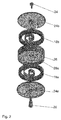
- FIG. 1 a timepiece cylinder 10 illustrating the invention.
- This barrel 10 comprises a drum 14 which defines two compartments 16a, 16b superimposed with reference to the geometric axis of the barrel and each containing a spring 18a, 18b wound in a spiral.
- the barrel comprises a first and a second tubular hubs, separated.
- the first hub 22a is secured to a first cover 24a.
- the first hub 22a is housed at least partially in the first compartment 16a, said lower with reference to the figure 1
- the second hub 22b is secured of a second cover 24b, and is housed at least partially in the second compartment 16b, said upper with reference to the figure 1 .
- Each of the springs 18b, 18a is spirally wound. Their inner end cooperates respectively with a hook which are provided with the first and second hubs and their outer end cooperates with the drum 14.
- the compartments are open on the side of the lids.
- cover is meant the element that covers or even closes a compartment of the drum.
- the first 24a and second 24b covers are free with reference to the drum 14 and are separated from the drum by a gap 30.
- the covers 24a and 24b are each provided with a peripheral toothing while the drum 14 is free of teeth. One of these teeth is used to arm the springs, while the other is used as PTO, to supply energy to a finishing gear of a timepiece in which is mounted the cylinder according to the invention .
- the skilled person can choose to use one or other of the lids for winding or for supply energy.
- covers 24a, 24b are independent of the drum 14, there may be a drum 14 of diameter greater than that of one or both covers 24a, 24b, which increases the number of turns of the springs. 18a, 18b and therefore, the power reserve available.
- the covers may be supported, each on a shoulder 25a, 25b that respectively comprise the hubs 22a and 22b.
- the drum 14 comprises a cylindrical wall 26 and a flat wall 28, projecting with reference to the cylindrical wall 26.
- the flat wall 28 is disposed substantially at mid-height of the cylindrical wall 26 and delimits the compartments 16a, 16b.
- the cylindrical wall 26 and the flat wall 28 are integrally formed.
- the plane wall 28 defines, at its center, an opening 28a positioned and dimensioned so as to substantially extend a channel formed by the hubs 22a and 22b. At the opening 28a, the flat wall may have an extra thickness to position the hubs in height. Between the lower hubs 22a and 22b and the walls of the drum 14, compartments 16a and 16b are thus defined.
- compartments 16a, 16b take place, respectively, the first spiral spring 18a and the second spiral spring 18b.
- the inner end cooperates with the lower hub 22a or the upper hub 22b, via the hooks mentioned above.
- the outer end of the springs 18a, 18b cooperates with the cylindrical wall 26 of the drum 14.
- the skilled person may consider making a fixed or sliding cooperation, of a type known in the field of barrels.
- the two springs 18a, 18b are mounted so that the spirals they describe are in opposite directions.
- the two springs of the barrel 10 being interconnected via the cylindrical wall 26 of the drum 14, they are thus arranged in series.
- At least one of the covers is provided on its face facing the compartments with an anti-friction coating 50.
- the two covers are thus provided with such antifriction coating 50.
- the flat wall 28 may be provided on at least one of its faces facing the compartments, preferably on both sides, an anti-friction coating.
- the friction coating can be achieved by a washer fixed to the cover 24a, 24b or to the flat wall 28.
- the washer can be glued or deposited on the cover or on the flat wall.
- a housing can be provided in the covers and / or in the flat wall, to accommodate the coating.
- the antifriction coating may be made of a material selected from PTFE (polytetrafluoroethylene), or DLC (diamond like carbon), or silicon, or in another hard material within the reach of the skilled person.
- PTFE polytetrafluoroethylene
- DLC diamond like carbon
- silicon silicon
- the barrel 10 according to the invention does not have a pivot, in the usual sense of the term in terms of timepieces.
- the barrels of the state of the art comprise an axis on which is mounted the inner end of the spring.
- the ends of the axis define pivots which pivot in bearings of the frame of the timepiece in which the barrel is mounted.
- the hubs and the drum pivot on a fixed shaft which takes place in the channel defined by the hubs 22a and 22b and by the central opening 28a of the flat wall.
- the shaft 20 is arranged in the frame of the timepiece.
- the barrel as defined by the present invention forms a functional whole constituted by the hubs 22a and 22b, the drum 14 and the springs 18a and 18b. According to this definition, the barrel pivots on the shaft 20 which is associated with it.
- the shaft 20 serves to guide the barrel in rotation, without defining a pivot relative to the frame of the timepiece.
- the shaft 20 may advantageously comprise bearing surfaces 20a, 20b for positioning in height, that is to say along the axis of the shaft, the hubs 22a and 22b and the drum 14.
- the shaft also participates in defining means for axial positioning of the barrel, to maintain the relative positioning of the components of the barrel.
- the shaft 20 can receive a screw 34 or a nut, clamped against a third bearing 20c of the shaft. It will be noted that the axial positioning means do not force the hubs against each other and leave them free to rotate.
- the shaft 20 is provided to be assembled on the timepiece independently of the constituents of the barrel.
- the shaft participates in both the axial positioning means and the rotating guide means.
- the shaft can thus receive a bearing screw 34 or a nut holding the hubs and the drum axially.
- the shaft is intended to be free and independent from the plate and defines only the axial positioning means.
- the means for guiding the drum in rotation is a bearing 52 acting at the periphery of the drum.
- the bearing serves as an interface between the drum and the frame of the timepiece and allows to suspend the barrel without the use of a bridge. External rollers could also be used to pivot the drum.
- the lower hub 22a serves as a rotational guide for the upper hub 22b.
- the lower hub 22a can advantageously participate in the axial positioning means, receiving, at its end, a nut or a bearing screw 34.
- the lower hub forms a tube that can be positioned on a fixed shaft integral with the timepiece.
- the barrel can thus form an independent, functional assembly, without pivot or axis of rotation, which can be assembled independently of the timepiece and then be mounted on the axis, previously fixed to the timepiece.
- the springs can be connected to their respective hub by rotating each of the hubs until its hook cooperates with the inner end of the spring.
- the proposed constructions are advantageously simple in that they comprise a small number of parts and a small footprint. Both springs can be mounted independently of each other, which also facilitates assembly operations.
- This return can, for example, be the average wheel of the movement.
- springs used either springs of the automatic winding type, that is to say allowing a limitation of the arming, or springs of the manual winding type, cooperating rigidly with the drum 14.
Landscapes
- Physics & Mathematics (AREA)
- General Physics & Mathematics (AREA)
- Springs (AREA)
- Electric Clocks (AREA)
- Electromechanical Clocks (AREA)
- Measurement Of Unknown Time Intervals (AREA)
- Details Of Rigid Or Semi-Rigid Containers (AREA)
Description
- La présente invention se rapporte au domaine de l'horlogerie mécanique. Elle se rapporte plus particulièrement à un barillet comprenant :
- un tambour définissant un premier et un deuxième compartiments superposés,
- un premier moyeu tubulaire solidaire d'un premier couvercle et logé au moins partiellement dans le premier compartiment,
- un deuxième moyeu tubulaire solidaire d'un deuxième couvercle logé au moins partiellement dans le deuxième compartiment.
- Chaque compartiment contient un ressort enroulé en spirale dont une première extrémité intérieure coopère avec le premier et le deuxième moyeux respectivement et dont une deuxième extrémité coopère avec le tambour.
- Dans les montres mécaniques, l'énergie est généralement fournie par des ressorts enroulés en spirale et logés dans des barillets. Selon les cas, on cherche à obtenir le maximum d'énergie dans un volume donné pour optimiser le couple transmis et la réserve de marche, c'est-à-dire la durée maximale pendant laquelle le barillet peut faire fonctionner le mouvement dans des conditions correctes. Ces paramètres sont théoriquement améliorés en augmentant la hauteur des spires (c'est-à-dire la dimension perpendiculaire au plan du spiral) et en diminuant l'épaisseur de la lame formant le spiral permettant un plus grand nombre de spires pour un barillet de diamètre constant. Cependant, les contraintes de fabrication des ressorts limitent rapidement les possibilités d'augmentation de la hauteur ou de réduction de l'épaisseur.
- On a déjà proposé, dans l'état de la technique, d'associer plusieurs barillets, soit en parallèle, soit en série, afin d'améliorer le couple transmis ou la réserve de marche. Par exemple, le document
US4363553 propose une construction dans laquelle deux barillets, contenant chacun un ressort, sont assemblés en série. - Le document
US249845 divulgue un barillet comprenant deux ressorts superposés. - La présente invention a pour but de proposer une construction alternative et avantageuse, permettant d'améliorer les performances énergétiques d'un barillet dans un encombrement limité.
- De façon plus précise, l'invention concerne un barillet ainsi qu'une pièce d'horlogerie et son procédé de montage tels que définis dans les revendications.
- D'autres détails de l'invention apparaîtront plus clairement à la lecture de la description qui suit, faite en référence au dessin annexé dans lequel :
- la
figure 1 est une vue en coupe d'un premier mode de réalisation de l'invention, - la figue 2 propose une vue en éclaté de ce même premier mode de réalisation, et
- les
figures 3 ,4 et5 sont des vues en coupe d'un deuxième et d'un troisième modes de réalisation de l'invention. - On peut voir sur la
figure 1 , un barillet 10 de pièce d'horlogerie illustrant l'invention. Ce barillet 10 comprend un tambour 14 qui définit deux compartiments 16a, 16b superposés en référence à l'axe géométrique du barillet et contenant chacun un ressort 18a, 18b enroulés en spirale. - Plus précisément, le barillet comporte un premier et un deuxième moyeux tubulaires, séparés. Le premier moyeu 22a est solidaire d'un premier couvercle 24a. Le premier moyeu 22a est logé au moins partiellement dans le premier compartiment 16a, dit inférieur en référence à la
figure 1 , tandis que le deuxième moyeu 22b est solidaire d'un deuxième couvercle 24b, et est logé au moins partiellement dans le deuxième compartiment 16b, dit supérieur en référence à lafigure 1 . - Chacun des ressorts 18b, 18a est enroulé en spirale. Leur extrémité intérieure coopère respectivement avec un crochet dont sont dotés le premier et le deuxième moyeux et leur extrémité extérieure coopère avec le tambour 14.
- Les compartiments sont ouverts du côté des couvercles. Par couvercle, on entend l'élément qui recouvre, voire ferme, un compartiment du tambour. Dans le cas de l'invention, les premier 24a et deuxième 24b couvercles sont libres en référence au tambour 14 et sont séparés du tambour par un interstice 30. Les couvercles 24a et 24b sont chacun munis d'une denture périphérique tandis que le tambour 14 est libre de denture. L'une de ces dentures est utilisée pour armer les ressorts, tandis que l'autre est utilisée comme prise de force, pour alimenter en énergie un rouage de finissage d'une pièce d'horlogerie dans laquelle est monté le barillet selon l'invention. Selon la construction de la pièce d'horlogerie dans laquelle le barillet selon l'invention est destiné à être monté, l'homme du métier peut choisir d'utiliser l'un ou l'autre des couvercles pour l'armage ou pour la fourniture d'énergie.
- Grâce au fait que les couvercles 24a, 24b sont indépendants du tambour 14, on peut avoir un tambour 14 de diamètre supérieur à celui de l'un ou des deux couvercles 24a, 24b, ce qui permet d'augmenter le nombre de tours des ressorts 18a, 18b et donc, la réserve de marche disponible. Les couvercles peuvent être appuyés, chacun sur un épaulement 25a, 25b que comportent respectivement les moyeux 22a et 22b.
- Dans les variantes proposées aux figures, le tambour 14 comporte une paroi cylindrique 26 et une paroi plane 28, s'étendant en saillie en référence à la paroi cylindrique 26. La paroi plane 28 est disposée sensiblement à mi-hauteur de la paroi cylindrique 26 et délimite les compartiments 16a, 16b. De préférence, la paroi cylindrique 26 et la paroi plane 28 sont venues d'une pièce.
- La paroi plane 28 définit, en son centre, une ouverture 28a positionnée et dimensionnée de manière à sensiblement prolonger un canal formé par les moyeux 22a et 22b. Au niveau de l'ouverture 28a, la paroi plane peut présenter une surépaisseur permettant de positionner en hauteur les moyeux. Entre les moyeux inférieur 22a et supérieur 22b et les parois du tambour 14, sont ainsi définis les compartiments 16a et 16b.
- Dans ces compartiments 16a, 16b prennent place, respectivement, le premier ressort en spiral 18a et le deuxième ressort en spiral 18b. Pour chacun d'eux, l'extrémité intérieure coopère avec le moyeu inférieur 22a ou le moyeu supérieur 22b, via les crochets mentionnés ci-dessus. L'extrémité extérieure des ressorts 18a, 18b coopère avec la paroi cylindrique 26 du tambour 14. L'homme du métier pourra envisager de réaliser une coopération fixe ou glissante, de type connu dans le domaine des barillets.
- Comme le montre la
figure 2 , les deux ressorts 18a, 18b sont montés de sorte que les spirales qu'ils décrivent, sont en sens inverse. Les deux ressorts du barillet 10 étant reliés entre eux via la paroi cylindrique 26 du tambour 14, ils sont ainsi agencés en série. - De manière avantageuse, ainsi qu'illustré sur la
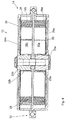
figure 3 , au moins un des couvercles est muni, sur sa face située en regard des compartiments, d'un revêtement antifriction 50. De préférence, les deux couvercles sont ainsi dotés d'un tel revêtement antifriction 50. De même, bien que non représenté sur les dessins, la paroi plane 28 peut être munie, sur au moins une de ses faces situées en regard des compartiments, de préférence sur les deux faces, d'un revêtement antifriction. - Le revêtement antifriction peut être réalisé par une rondelle fixée au couvercle 24a, 24b ou à la paroi plane 28. La rondelle peut être collée ou déposée sur le couvercle ou sur la paroi plane. Un logement peut être prévu dans les couvercles et/ou dans la paroi plane, pour accueillir le revêtement. Le revêtement antifriction peut être réalisé dans un matériau choisi parmi du PTFE (polytétrafluoroéthylène), ou du DLC (diamond like carbon), ou du silicium, ou dans un autre matériau dur à la portée de l'homme du métier. On peut obtenir un effet esthétique intéressant en rendant visible le revêtement antifriction 50 dont est muni le couvercle, au travers d'ouvertures ménagées dans le couvercle.
- De manière particulièrement avantageuse, on peut constater que le barillet 10 selon l'invention ne comporte pas de pivot, au sens usuel du terme en matière d'horlogerie. En effet, de manière générale, les barillets de l'état de la technique comportent un axe sur lequel est montée l'extrémité intérieure du ressort. Les extrémités de l'axe définissent des pivots qui pivotent dans des paliers du bâti de la pièce d'horlogerie dans laquelle le barillet est monté. Selon l'invention, les moyeux et le tambour pivotent sur un arbre 20 fixe qui prend place dans le canal défini par les moyeux 22a et 22b et par l'ouverture centrale 28a de la paroi plane. Dans le mode de réalisation de la
figure 1 , l'arbre 20 est agencé dans le bâti de la pièce d'horlogerie. Le barillet tel que défini par la présente invention, forme un tout fonctionnel constitué par les moyeux 22a et 22b, le tambour 14 et les ressorts 18a et 18b. Selon cette définition, le barillet pivote sur l'arbre 20 qui lui est associé. - L'arbre 20 sert de guidage en rotation du barillet, sans définir de pivot par rapport au bâti de la pièce d'horlogerie. Dans le mode de réalisation de la
figure 1 , l'arbre 20 peut avantageusement comporter des portées 20a, 20b permettant de positionner en hauteur, c'est-à-dire selon l'axe de l'arbre, les moyeux 22a et 22b et le tambour 14. Ainsi, l'arbre participe également à définir des moyens de positionnement axial du barillet, permettant de maintenir le positionnement relatif des éléments composant le barillet. L'arbre 20 peut recevoir une vis à portée 34 ou un écrou, serrée contre une troisième portée 20c de l'arbre. On notera que les moyens de positionnement axial ne contraignent pas les moyeux l'un contre l'autre et les laissent libres en rotation. - Dans le mode de réalisation de la
figure 3 , l'arbre 20 est prévu pour pouvoir être assemblé sur la pièce d'horlogerie de manière indépendante par rapport aux constituants du barillet. Tout comme pour la première variante, l'arbre participe à la fois aux moyens de positionnement axial et aux moyens de guidage en rotation. L'arbre peut ainsi recevoir une vis à portée 34 ou un écrou maintenant axialement les moyeux et le tambour. - Dans la variante de la
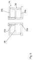
figure 4 , l'arbre est destiné à être libre et indépendant par rapport à la platine et ne définit que les moyens de positionnement axial. Le moyen de guidage en rotation du tambour est un roulement 52 agissant à la périphérie du tambour. Le roulement sert d'interface entre le tambour et le bâti de la pièce d'horlogerie et permet de suspendre le barillet, sans utilisation de pont. On pourrait également utiliser des galets extérieurs pour assurer le pivotement du tambour. - Pour le montage du barillet, on effectue les étapes suivantes :
- monter le moyeu inférieur 22a sur l'arbre 20,
- monter le tambour 14 associé aux ressorts 18a et 18b sur l'arbre 20,
- relier le ressort inférieur 18a au moyeu inférieur 22a,
- monter le moyeu supérieur 22b sur l'arbre 20,
- relier le ressort supérieur 18b au moyeu supérieur 22b,
- positionner les moyens de positionnement axial, en l'espèce en serrant la vis 34 dans l'arbre 20.
- Dans la variante schématisée à la
figure 5 , le moyeu inférieur 22a sert de guidage en rotation pour le moyeu supérieur 22b. Le moyeu inférieur 22a peut, de manière avantageuse, participer aux moyens de positionnement axial, en recevant, à son extrémité, un écrou ou une vis à portée 34. Le moyeu inférieur forme un tube susceptible d'être positionné sur un axe monté solidaire de la pièce d'horlogerie. Le barillet peut ainsi former un ensemble indépendant, fonctionnel, sans pivot ni axe de rotation, pouvant être assemblé indépendamment de la pièce d'horlogerie et être ensuite monté sur l'axe, préalablement fixé à la pièce d'horlogerie. - Dans ce mode de réalisation, le moyeu inférieur joue également le rôle de l'arbre. Ainsi, on effectue les étapes suivantes.
- se doter du moyeu inférieur 22a,
- monter le tambour 14 associé aux ressorts 18a et 18b sur le moyeu inférieur 22a,
- relier le ressort inférieur 18a au moyeu inférieur 22a,
- monter le moyeu supérieur 22b sur le moyeu inférieur 22a,
- relier le ressort supérieur 18b au moyeu supérieur 22b,
- positionner les moyens de positionnement axial, en l'espèce en serrant la vis 34 dans le moyeu inférieur 22a.
- On notera que d'un point de vue pratique, les ressorts peuvent être reliés à leur moyeu respectif en faisant tourner chacun des moyeux jusqu'à ce que son crochet coopère avec l'extrémité intérieure du ressort.
- Ainsi, si le barillet 10 est connecté avec le système de remontage par le couvercle inférieur 24a, on va armer le ressort inférieur 18a via le moyeu inférieur 22a. Progressivement, le ressort inférieur 18a se dévide dans le ressort supérieur 18b, via le tambour 14, entraînant l'armage du ressort supérieur 18b. Le couple est alors disponible au niveau du couvercle supérieur 24b, via le moyeu supérieur 22b. On peut également inverser cette disposition en reliant le couvercle supérieur au système de remontage et le couvercle inférieur au rouage de finissage.
- Les constructions proposées sont avantageusement simples en ce qu'elles comprennent un nombre réduit de pièces et un encombrement faible. Les deux ressorts peuvent être montés indépendamment l'un de l'autre, ce qui facilite également les opérations d'assemblage.
- On obtient ainsi un barillet 10 intégrant deux ressorts 18a, 18b, permettant d'augmenter le couple fourni par le barillet ou la réserve de marche. On peut alors proposer d'associer de tels barillets, en série ou en parallèle, par exemple en reliant deux barillets 10 tels que décrits ci-dessus, au moyen d'un renvoi, engrenant avec le couvercle supérieur des deux barillets 10. Ce renvoi peut, par exemple, être la roue de moyenne du mouvement.
- L'homme du métier pourra choisir les ressorts utilisés, soit des ressorts de type remontage automatique, c'est-à-dire permettant une limitation de l'armage, soit des ressorts de type remontage manuel, coopérant rigidement avec le tambour 14.
Claims (16)
- Barillet de pièce d'horlogerie, comprenant :- un tambour (14) définissant un premier (16a) et un deuxième (16b) compartiments superposés,- un premier moyeu (22a) tubulaire solidaire d'un premier couvercle (24a) et logé au moins partiellement dans le premier compartiment,- un deuxième moyeu (22b) tubulaire solidaire d'un deuxième couvercle (24b) logé au moins partiellement dans le deuxième compartiment,chaque compartiment contenant un ressort (18a, 18b) enroulé en spirale dont une première extrémité intérieure coopère respectivement avec le premier et le deuxième moyeux et dont une deuxième extrémité coopère avec le tambour (14),
lesdits compartiments étant ouverts du côté des couvercles et en ce que ledit premier et deuxième couvercles sont libres en référence au tambour (14) et sont chacun munis d'une denture périphérique tandis que le tambour (14) est libre de denture. - Barillet selon la revendication 1, caractérisé en ce que ledit barillet, en tant que tel, ne comporte pas de pivot destiné à pivoter sur une platine de pièce d'horlogerie.
- Barillet selon la revendication 1, caractérisé en ce qu'au moins un desdits premier et deuxième couvercles est muni, sur sa face située en regard, respectivement dudit premier ou deuxième compartiment, d'un revêtement antifriction (50).
- Barillet selon l'une des revendications précédentes, caractérisé en ce que ledit tambour (14) comporte une paroi cylindrique (26) et une paroi plane (28), s'étendant en saillie en référence à la paroi cylindrique (26), ladite paroi plane (28) délimitant lesdits compartiments.
- Barillet selon la revendication 4, caractérisé en ce que ladite paroi plane (28) est munie, sur au moins une de ses faces situées en regard dudit premier ou deuxième compartiment, d'un revêtement antifriction (50).
- Barillet selon la revendication 4 ou la revendication 5, caractérisé en ce que ladite paroi cylindrique (26) et la paroi plane (28) sont venues d'une pièce.
- Barillet selon l'une des revendications 3 à 6, caractérisé en ce que ledit revêtement antifriction est réalisé par une rondelle fixée au couvercle ou à ladite paroi plane.
- Barillet selon l'une des revendications 3 à 7, caractérisé en ce que ledit revêtement antifriction (50) est réalisé dans un matériau choisi parmi du PTFE, ou du DLC ou du silicium.
- Barillet selon l'une des revendications 3 à 8, caractérisé en ce que ledit revêtement antifriction dont est muni le couvercle, est visible au travers d'ouvertures ménagées dans le couvercle.
- Barillet selon l'une des revendications précédentes, caractérisé en ce que lesdits premier et deuxième moyeux sont positionnés par des moyens de positionnement axial les positionnant l'un en référence à l'autre.
- Barillet selon la revendication 10, caractérisé en ce que le premier moyeu (22a) est logé dans le premier (16a) et dans le deuxième (16b) compartiments et en ce que le deuxième moyeu (22b) est pivoté sur le premier moyeu (22a), les moyens de positionnement axial étant agencés pour coopérer avec ledit premier moyeu (22a).
- Barillet selon l'une des revendications précédentes, caractérisé en ce qu'il est associé à un arbre (20) de guidage en rotation, ledit arbre étant destiné à être fixe.
- Pièce d'horlogerie comprenant un barillet selon la revendication 10 et un moyen de guidage en rotation du tambour (14).
- Pièce d'horlogerie selon la revendication 13, caractérisée en ce que ledit moyen de guidage en rotation du tambour est agencé de manière à agir à la périphérie du tambour, ledit barillet étant suspendu.
- Pièce d'horlogerie selon la revendication 13, caractérisée en ce que ledit moyen de guidage en rotation est un axe solidaire du bâti de la pièce d'horlogerie et en ce que ledit axe participe aux moyens de positionnement axial du barillet.
- Procédé de montage d'une pièce d'horlogerie selon la revendication 15, caractérisé en ce qu'il comporte les étapes suivantes :- monter le premier moyeu (22a) sur l'arbre (20),- monter le tambour (14) associé aux ressorts (18b, 18a) sur le premier moyeu (22a),- relier le premier ressort (18a) au premier moyeu (22a),- monter le deuxième moyeu (22b) sur l'arbre,- relier le deuxième ressort (18b) au deuxième moyeu (22b),- positionner les moyens de positionnement axial sur l'arbre (20).
Applications Claiming Priority (2)
| Application Number | Priority Date | Filing Date | Title |
|---|---|---|---|
| CH00340/12A CH706214B1 (fr) | 2012-03-09 | 2012-03-09 | Barillet de pièce d'horlogerie. |
| PCT/EP2013/054765 WO2013132076A1 (fr) | 2012-03-09 | 2013-03-08 | Barillet |
Publications (2)
| Publication Number | Publication Date |
|---|---|
| EP2823364A1 EP2823364A1 (fr) | 2015-01-14 |
| EP2823364B1 true EP2823364B1 (fr) | 2016-05-25 |
Family
ID=47901045
Family Applications (1)
| Application Number | Title | Priority Date | Filing Date |
|---|---|---|---|
| EP13710338.8A Not-in-force EP2823364B1 (fr) | 2012-03-09 | 2013-03-08 | Barillet |
Country Status (7)
| Country | Link |
|---|---|
| US (1) | US9335738B2 (fr) |
| EP (1) | EP2823364B1 (fr) |
| JP (1) | JP6072837B2 (fr) |
| CN (1) | CN104220939B (fr) |
| CH (1) | CH706214B1 (fr) |
| HK (1) | HK1204100A1 (fr) |
| WO (1) | WO2013132076A1 (fr) |
Families Citing this family (10)
| Publication number | Priority date | Publication date | Assignee | Title |
|---|---|---|---|---|
| EP2218792A4 (fr) | 2007-11-20 | 2010-12-08 | Olympus Corp | Procédé de préparation d'échantillon fécal, solution pour préparer un échantillon fécal et nécessaire de collecte de fèces |
| CN108196438B (zh) * | 2012-04-04 | 2020-09-08 | 劳力士有限公司 | 轴、发条及包括轴和发条的发条盒、钟表机芯、腕表和表 |
| EP2887150A1 (fr) * | 2013-12-20 | 2015-06-24 | ETA SA Manufacture Horlogère Suisse | Barillet d'horlogerie optimisé |
| EP2952979B1 (fr) * | 2014-06-03 | 2017-03-01 | Nivarox-FAR S.A. | Composant horloger à base de verre photostructurable |
| EP3208666B1 (fr) * | 2016-02-19 | 2018-11-21 | Blancpain SA | Roue d'horlogerie a rattrapage de jeu |
| CH712308A1 (fr) * | 2016-03-30 | 2017-10-13 | Officine Panerai Ag | Système de barillet autolubrifié pour pièce d'horlogerie. |
| CN107817670A (zh) * | 2016-09-13 | 2018-03-20 | 天津海鸥表业集团有限公司 | 一种双发条手表原动组件 |
| DE102016122936B4 (de) * | 2016-11-28 | 2018-11-08 | Lange Uhren Gmbh | Federhaus für eine Uhr |
| EP3654109B1 (fr) * | 2018-11-13 | 2021-03-31 | Patek Philippe SA Genève | Pièce d'horlogerie comprenant deux sources d'énergie |
| CN109579662A (zh) * | 2019-01-28 | 2019-04-05 | 汉中万目仪电有限责任公司 | 杯底规 |
Family Cites Families (20)
| Publication number | Priority date | Publication date | Assignee | Title |
|---|---|---|---|---|
| US410327A (en) * | 1889-09-03 | meylan | ||
| US249845A (en) * | 1881-11-22 | Strike-spring for eight-day clocks | ||
| BE567865A (fr) * | ||||
| GB103121A (fr) * | 1915-12-31 | 1918-05-02 | Wuthrich Edouard | |
| CH90009A (fr) * | 1917-10-18 | 1921-07-16 | Victor Talking Machine Co | Moteur à ressort multiple. |
| GB147339A (en) * | 1919-12-16 | 1920-07-22 | Thomas Frederick Redington | Improvements in spring-driven mechanism |
| US1796374A (en) * | 1930-02-13 | 1931-03-17 | Albert F Kendle | Mainspring barrel |
| CH599580B5 (fr) * | 1974-08-22 | 1978-05-31 | Longines Montres Comp D | |
| JPS5194389U (fr) * | 1975-01-28 | 1976-07-29 | ||
| IT1074807B (it) * | 1976-02-18 | 1985-04-20 | Bouchet Lassale Sa | Dispositivo di imperniamento per bariletto d'orologio |
| ATE390651T1 (de) * | 2000-01-06 | 2008-04-15 | Chopard Manufacture Sa | Antriebsvorrichtung für uhrwerk mit grosser gangreserve |
| DE10357228A1 (de) * | 2003-12-08 | 2005-07-07 | Lange Uhren Gmbh | Federhausvorrichtung |
| EP1582943B1 (fr) * | 2004-04-01 | 2008-09-03 | Richemont International S.A. | Mouvement de montre comportant plusieurs barillets |
| CN201116972Y (zh) * | 2007-08-28 | 2008-09-17 | 天津海鸥表业集团有限公司 | 手表串联式原动机构 |
| EP2060957A1 (fr) * | 2007-11-16 | 2009-05-20 | ETA SA Manufacture Horlogère Suisse | Organe moteur à ressorts pour mouvement d'horlogerie |
| CN201181396Y (zh) * | 2008-03-31 | 2009-01-14 | 天津海鸥表业集团有限公司 | 手表同轴双层条盒联动机构 |
| CH699988A2 (fr) * | 2008-11-28 | 2010-05-31 | Patek Philippe Sa Geneve | Organe moteur pour mouvement horloger. |
| CH702856A2 (fr) * | 2010-03-22 | 2011-09-30 | Patek Philippe Sa Geneve | Mouvement de montre. |
| CH704249B1 (fr) * | 2010-12-20 | 2015-02-27 | Elsbeth Roesner | Organe moteur pour mouvement horloger. |
| CH706641A2 (fr) * | 2012-06-22 | 2013-12-31 | Cartier Creation Studio Sa | Organe moteur pour mouvement d'horlogerie. |
-
2012
- 2012-03-09 CH CH00340/12A patent/CH706214B1/fr unknown
-
2013
- 2013-03-08 WO PCT/EP2013/054765 patent/WO2013132076A1/fr active Application Filing
- 2013-03-08 CN CN201380012942.5A patent/CN104220939B/zh not_active Expired - Fee Related
- 2013-03-08 JP JP2014560400A patent/JP6072837B2/ja not_active Expired - Fee Related
- 2013-03-08 EP EP13710338.8A patent/EP2823364B1/fr not_active Not-in-force
- 2013-03-08 US US14/383,635 patent/US9335738B2/en active Active
-
2015
- 2015-05-06 HK HK15104318.0A patent/HK1204100A1/zh not_active IP Right Cessation
Also Published As
| Publication number | Publication date |
|---|---|
| US20150138932A1 (en) | 2015-05-21 |
| CN104220939A (zh) | 2014-12-17 |
| JP6072837B2 (ja) | 2017-02-01 |
| JP2015509600A (ja) | 2015-03-30 |
| US9335738B2 (en) | 2016-05-10 |
| HK1204100A1 (zh) | 2015-11-06 |
| WO2013132076A1 (fr) | 2013-09-12 |
| EP2823364A1 (fr) | 2015-01-14 |
| CN104220939B (zh) | 2016-10-12 |
| CH706214B1 (fr) | 2016-09-30 |
| CH706214A1 (fr) | 2013-09-13 |
Similar Documents
| Publication | Publication Date | Title |
|---|---|---|
| EP2823364B1 (fr) | Barillet | |
| EP2080066B1 (fr) | Piece d'horlogerie | |
| EP2212749B1 (fr) | Organe moteur a ressorts pour mouvement d'horlogerie | |
| EP2437125B1 (fr) | Pièce d'horlogerie | |
| EP2255257A1 (fr) | Organe de pivotement | |
| WO2005096104A1 (fr) | Mouvement de montre comportant plusieurs barillets | |
| EP3106927B1 (fr) | Indicateur de réserve de marche pour pièce d'horlogerie | |
| EP2264551B1 (fr) | Engrenage differentiel pour mouvement horloger | |
| EP3172626A1 (fr) | Pivot à lame | |
| WO2004070478A2 (fr) | Masse oscillante | |
| EP2725433A1 (fr) | Tourbillon volant a balancier volant pour mouvement horloger | |
| EP2564276B1 (fr) | Pièce d'horlogerie | |
| EP2466393B1 (fr) | Ressort de barillet contenant un tel ressort | |
| EP3889688B1 (fr) | Organe moteur pour pièce d'horlogerie | |
| EP2869139B1 (fr) | Mécanisme de tourbillon | |
| EP3066527B1 (fr) | Système de fusée | |
| EP2869134B1 (fr) | Système de barillet pour pièce d'horlogerie | |
| EP3761122B1 (fr) | Mobile d'échappement horloger, mécanisme d'échappement et pièce d'horlogerie associés | |
| EP2757425A2 (fr) | Pièce d'horlogerie comportant un affichage de réserve de marche par des organes polarisés présentant une orientation relative variable | |
| EP3112949B1 (fr) | Source d'energie mecanique pour mouvement horloger | |
| WO2010108884A1 (fr) | Balancier a inertie reglable | |
| CH714303A1 (fr) | Système décoratif pour pièce d'horlogerie ou de bijouterie. | |
| EP3470932A1 (fr) | Oscillateur pour mouvement horloger | |
| CH716502A2 (fr) | Mouvement d'horlogerie mécanique à remontage automatique. | |
| CH710636B1 (fr) | Mécanisme de remontage à engrenage planétaire sphérique pour mouvement horloger. |
Legal Events
| Date | Code | Title | Description |
|---|---|---|---|
| PUAI | Public reference made under article 153(3) epc to a published international application that has entered the european phase |
Free format text: ORIGINAL CODE: 0009012 |
|
| 17P | Request for examination filed |
Effective date: 20141009 |
|
| AK | Designated contracting states |
Kind code of ref document: A1 Designated state(s): AL AT BE BG CH CY CZ DE DK EE ES FI FR GB GR HR HU IE IS IT LI LT LU LV MC MK MT NL NO PL PT RO RS SE SI SK SM TR |
|
| AX | Request for extension of the european patent |
Extension state: BA ME |
|
| DAX | Request for extension of the european patent (deleted) | ||
| REG | Reference to a national code |
Ref country code: HK Ref legal event code: DE Ref document number: 1204100 Country of ref document: HK |
|
| GRAP | Despatch of communication of intention to grant a patent |
Free format text: ORIGINAL CODE: EPIDOSNIGR1 |
|
| RIC1 | Information provided on ipc code assigned before grant |
Ipc: G04B 1/12 20060101AFI20151030BHEP Ipc: G04B 1/16 20060101ALI20151030BHEP |
|
| INTG | Intention to grant announced |
Effective date: 20151207 |
|
| GRAS | Grant fee paid |
Free format text: ORIGINAL CODE: EPIDOSNIGR3 |
|
| GRAA | (expected) grant |
Free format text: ORIGINAL CODE: 0009210 |
|
| AK | Designated contracting states |
Kind code of ref document: B1 Designated state(s): AL AT BE BG CH CY CZ DE DK EE ES FI FR GB GR HR HU IE IS IT LI LT LU LV MC MK MT NL NO PL PT RO RS SE SI SK SM TR |
|
| REG | Reference to a national code |
Ref country code: GB Ref legal event code: FG4D Free format text: NOT ENGLISH |
|
| REG | Reference to a national code |
Ref country code: CH Ref legal event code: EP |
|
| REG | Reference to a national code |
Ref country code: IE Ref legal event code: FG4D Free format text: LANGUAGE OF EP DOCUMENT: FRENCH Ref country code: AT Ref legal event code: REF Ref document number: 802791 Country of ref document: AT Kind code of ref document: T Effective date: 20160615 |
|
| REG | Reference to a national code |
Ref country code: DE Ref legal event code: R096 Ref document number: 602013007929 Country of ref document: DE |
|
| REG | Reference to a national code |
Ref country code: CH Ref legal event code: NV Representative=s name: GLN S.A., CH |
|
| REG | Reference to a national code |
Ref country code: LT Ref legal event code: MG4D |
|
| REG | Reference to a national code |
Ref country code: NL Ref legal event code: MP Effective date: 20160525 |
|
| PG25 | Lapsed in a contracting state [announced via postgrant information from national office to epo] |
Ref country code: NL Free format text: LAPSE BECAUSE OF FAILURE TO SUBMIT A TRANSLATION OF THE DESCRIPTION OR TO PAY THE FEE WITHIN THE PRESCRIBED TIME-LIMIT Effective date: 20160525 Ref country code: LT Free format text: LAPSE BECAUSE OF FAILURE TO SUBMIT A TRANSLATION OF THE DESCRIPTION OR TO PAY THE FEE WITHIN THE PRESCRIBED TIME-LIMIT Effective date: 20160525 Ref country code: NO Free format text: LAPSE BECAUSE OF FAILURE TO SUBMIT A TRANSLATION OF THE DESCRIPTION OR TO PAY THE FEE WITHIN THE PRESCRIBED TIME-LIMIT Effective date: 20160825 Ref country code: FI Free format text: LAPSE BECAUSE OF FAILURE TO SUBMIT A TRANSLATION OF THE DESCRIPTION OR TO PAY THE FEE WITHIN THE PRESCRIBED TIME-LIMIT Effective date: 20160525 |
|
| REG | Reference to a national code |
Ref country code: AT Ref legal event code: MK05 Ref document number: 802791 Country of ref document: AT Kind code of ref document: T Effective date: 20160525 |
|
| PG25 | Lapsed in a contracting state [announced via postgrant information from national office to epo] |
Ref country code: PT Free format text: LAPSE BECAUSE OF FAILURE TO SUBMIT A TRANSLATION OF THE DESCRIPTION OR TO PAY THE FEE WITHIN THE PRESCRIBED TIME-LIMIT Effective date: 20160926 Ref country code: GR Free format text: LAPSE BECAUSE OF FAILURE TO SUBMIT A TRANSLATION OF THE DESCRIPTION OR TO PAY THE FEE WITHIN THE PRESCRIBED TIME-LIMIT Effective date: 20160826 Ref country code: RS Free format text: LAPSE BECAUSE OF FAILURE TO SUBMIT A TRANSLATION OF THE DESCRIPTION OR TO PAY THE FEE WITHIN THE PRESCRIBED TIME-LIMIT Effective date: 20160525 Ref country code: LV Free format text: LAPSE BECAUSE OF FAILURE TO SUBMIT A TRANSLATION OF THE DESCRIPTION OR TO PAY THE FEE WITHIN THE PRESCRIBED TIME-LIMIT Effective date: 20160525 Ref country code: SE Free format text: LAPSE BECAUSE OF FAILURE TO SUBMIT A TRANSLATION OF THE DESCRIPTION OR TO PAY THE FEE WITHIN THE PRESCRIBED TIME-LIMIT Effective date: 20160525 Ref country code: ES Free format text: LAPSE BECAUSE OF FAILURE TO SUBMIT A TRANSLATION OF THE DESCRIPTION OR TO PAY THE FEE WITHIN THE PRESCRIBED TIME-LIMIT Effective date: 20160525 |
|
| REG | Reference to a national code |
Ref country code: CH Ref legal event code: PFA Owner name: SOWIND S.A., CH Free format text: FORMER OWNER: SOWIND S.A., CH |
|
| PG25 | Lapsed in a contracting state [announced via postgrant information from national office to epo] |
Ref country code: EE Free format text: LAPSE BECAUSE OF FAILURE TO SUBMIT A TRANSLATION OF THE DESCRIPTION OR TO PAY THE FEE WITHIN THE PRESCRIBED TIME-LIMIT Effective date: 20160525 Ref country code: SK Free format text: LAPSE BECAUSE OF FAILURE TO SUBMIT A TRANSLATION OF THE DESCRIPTION OR TO PAY THE FEE WITHIN THE PRESCRIBED TIME-LIMIT Effective date: 20160525 Ref country code: DK Free format text: LAPSE BECAUSE OF FAILURE TO SUBMIT A TRANSLATION OF THE DESCRIPTION OR TO PAY THE FEE WITHIN THE PRESCRIBED TIME-LIMIT Effective date: 20160525 Ref country code: CZ Free format text: LAPSE BECAUSE OF FAILURE TO SUBMIT A TRANSLATION OF THE DESCRIPTION OR TO PAY THE FEE WITHIN THE PRESCRIBED TIME-LIMIT Effective date: 20160525 Ref country code: RO Free format text: LAPSE BECAUSE OF FAILURE TO SUBMIT A TRANSLATION OF THE DESCRIPTION OR TO PAY THE FEE WITHIN THE PRESCRIBED TIME-LIMIT Effective date: 20160525 |
|
| REG | Reference to a national code |
Ref country code: HK Ref legal event code: GR Ref document number: 1204100 Country of ref document: HK |
|
| PG25 | Lapsed in a contracting state [announced via postgrant information from national office to epo] |
Ref country code: AT Free format text: LAPSE BECAUSE OF FAILURE TO SUBMIT A TRANSLATION OF THE DESCRIPTION OR TO PAY THE FEE WITHIN THE PRESCRIBED TIME-LIMIT Effective date: 20160525 Ref country code: SM Free format text: LAPSE BECAUSE OF FAILURE TO SUBMIT A TRANSLATION OF THE DESCRIPTION OR TO PAY THE FEE WITHIN THE PRESCRIBED TIME-LIMIT Effective date: 20160525 Ref country code: PL Free format text: LAPSE BECAUSE OF FAILURE TO SUBMIT A TRANSLATION OF THE DESCRIPTION OR TO PAY THE FEE WITHIN THE PRESCRIBED TIME-LIMIT Effective date: 20160525 |
|
| REG | Reference to a national code |
Ref country code: DE Ref legal event code: R097 Ref document number: 602013007929 Country of ref document: DE |
|
| REG | Reference to a national code |
Ref country code: FR Ref legal event code: PLFP Year of fee payment: 5 |
|
| PLBE | No opposition filed within time limit |
Free format text: ORIGINAL CODE: 0009261 |
|
| STAA | Information on the status of an ep patent application or granted ep patent |
Free format text: STATUS: NO OPPOSITION FILED WITHIN TIME LIMIT |
|
| 26N | No opposition filed |
Effective date: 20170228 |
|
| PG25 | Lapsed in a contracting state [announced via postgrant information from national office to epo] |
Ref country code: SI Free format text: LAPSE BECAUSE OF FAILURE TO SUBMIT A TRANSLATION OF THE DESCRIPTION OR TO PAY THE FEE WITHIN THE PRESCRIBED TIME-LIMIT Effective date: 20160525 |
|
| PG25 | Lapsed in a contracting state [announced via postgrant information from national office to epo] |
Ref country code: MC Free format text: LAPSE BECAUSE OF FAILURE TO SUBMIT A TRANSLATION OF THE DESCRIPTION OR TO PAY THE FEE WITHIN THE PRESCRIBED TIME-LIMIT Effective date: 20160525 |
|
| REG | Reference to a national code |
Ref country code: IE Ref legal event code: MM4A |
|
| PG25 | Lapsed in a contracting state [announced via postgrant information from national office to epo] |
Ref country code: LU Free format text: LAPSE BECAUSE OF NON-PAYMENT OF DUE FEES Effective date: 20170308 |
|
| PG25 | Lapsed in a contracting state [announced via postgrant information from national office to epo] |
Ref country code: IE Free format text: LAPSE BECAUSE OF NON-PAYMENT OF DUE FEES Effective date: 20170308 |
|
| REG | Reference to a national code |
Ref country code: BE Ref legal event code: MM Effective date: 20170331 |
|
| REG | Reference to a national code |
Ref country code: FR Ref legal event code: PLFP Year of fee payment: 6 |
|
| PGFP | Annual fee paid to national office [announced via postgrant information from national office to epo] |
Ref country code: GB Payment date: 20180327 Year of fee payment: 6 |
|
| PG25 | Lapsed in a contracting state [announced via postgrant information from national office to epo] |
Ref country code: BE Free format text: LAPSE BECAUSE OF NON-PAYMENT OF DUE FEES Effective date: 20170331 |
|
| PGFP | Annual fee paid to national office [announced via postgrant information from national office to epo] |
Ref country code: FR Payment date: 20180326 Year of fee payment: 6 Ref country code: IT Payment date: 20180322 Year of fee payment: 6 |
|
| PGFP | Annual fee paid to national office [announced via postgrant information from national office to epo] |
Ref country code: DE Payment date: 20180328 Year of fee payment: 6 |
|
| PG25 | Lapsed in a contracting state [announced via postgrant information from national office to epo] |
Ref country code: MT Free format text: LAPSE BECAUSE OF FAILURE TO SUBMIT A TRANSLATION OF THE DESCRIPTION OR TO PAY THE FEE WITHIN THE PRESCRIBED TIME-LIMIT Effective date: 20160525 |
|
| PG25 | Lapsed in a contracting state [announced via postgrant information from national office to epo] |
Ref country code: AL Free format text: LAPSE BECAUSE OF FAILURE TO SUBMIT A TRANSLATION OF THE DESCRIPTION OR TO PAY THE FEE WITHIN THE PRESCRIBED TIME-LIMIT Effective date: 20160525 |
|
| REG | Reference to a national code |
Ref country code: CH Ref legal event code: NV Representative=s name: BOVARD SA NEUCHATEL CONSEILS EN PROPRIETE INTE, CH |
|
| PG25 | Lapsed in a contracting state [announced via postgrant information from national office to epo] |
Ref country code: HU Free format text: LAPSE BECAUSE OF FAILURE TO SUBMIT A TRANSLATION OF THE DESCRIPTION OR TO PAY THE FEE WITHIN THE PRESCRIBED TIME-LIMIT; INVALID AB INITIO Effective date: 20130308 |
|
| PG25 | Lapsed in a contracting state [announced via postgrant information from national office to epo] |
Ref country code: BG Free format text: LAPSE BECAUSE OF FAILURE TO SUBMIT A TRANSLATION OF THE DESCRIPTION OR TO PAY THE FEE WITHIN THE PRESCRIBED TIME-LIMIT Effective date: 20160525 |
|
| PGFP | Annual fee paid to national office [announced via postgrant information from national office to epo] |
Ref country code: CH Payment date: 20190404 Year of fee payment: 7 |
|
| REG | Reference to a national code |
Ref country code: DE Ref legal event code: R119 Ref document number: 602013007929 Country of ref document: DE |
|
| PG25 | Lapsed in a contracting state [announced via postgrant information from national office to epo] |
Ref country code: CY Free format text: LAPSE BECAUSE OF FAILURE TO SUBMIT A TRANSLATION OF THE DESCRIPTION OR TO PAY THE FEE WITHIN THE PRESCRIBED TIME-LIMIT Effective date: 20160525 |
|
| GBPC | Gb: european patent ceased through non-payment of renewal fee |
Effective date: 20190308 |
|
| PG25 | Lapsed in a contracting state [announced via postgrant information from national office to epo] |
Ref country code: MK Free format text: LAPSE BECAUSE OF FAILURE TO SUBMIT A TRANSLATION OF THE DESCRIPTION OR TO PAY THE FEE WITHIN THE PRESCRIBED TIME-LIMIT Effective date: 20160525 |
|
| PG25 | Lapsed in a contracting state [announced via postgrant information from national office to epo] |
Ref country code: GB Free format text: LAPSE BECAUSE OF NON-PAYMENT OF DUE FEES Effective date: 20190308 Ref country code: DE Free format text: LAPSE BECAUSE OF NON-PAYMENT OF DUE FEES Effective date: 20191001 |
|
| PG25 | Lapsed in a contracting state [announced via postgrant information from national office to epo] |
Ref country code: FR Free format text: LAPSE BECAUSE OF NON-PAYMENT OF DUE FEES Effective date: 20190331 Ref country code: IT Free format text: LAPSE BECAUSE OF NON-PAYMENT OF DUE FEES Effective date: 20190308 |
|
| PG25 | Lapsed in a contracting state [announced via postgrant information from national office to epo] |
Ref country code: TR Free format text: LAPSE BECAUSE OF FAILURE TO SUBMIT A TRANSLATION OF THE DESCRIPTION OR TO PAY THE FEE WITHIN THE PRESCRIBED TIME-LIMIT Effective date: 20160525 |
|
| PG25 | Lapsed in a contracting state [announced via postgrant information from national office to epo] |
Ref country code: HR Free format text: LAPSE BECAUSE OF FAILURE TO SUBMIT A TRANSLATION OF THE DESCRIPTION OR TO PAY THE FEE WITHIN THE PRESCRIBED TIME-LIMIT Effective date: 20160525 |
|
| PG25 | Lapsed in a contracting state [announced via postgrant information from national office to epo] |
Ref country code: IS Free format text: LAPSE BECAUSE OF FAILURE TO SUBMIT A TRANSLATION OF THE DESCRIPTION OR TO PAY THE FEE WITHIN THE PRESCRIBED TIME-LIMIT Effective date: 20160925 |
|
| REG | Reference to a national code |
Ref country code: CH Ref legal event code: PL |
|
| PG25 | Lapsed in a contracting state [announced via postgrant information from national office to epo] |
Ref country code: LI Free format text: LAPSE BECAUSE OF NON-PAYMENT OF DUE FEES Effective date: 20200331 Ref country code: CH Free format text: LAPSE BECAUSE OF NON-PAYMENT OF DUE FEES Effective date: 20200331 |