EP2823113B1 - Vorrichtung zum befestigen einer schiene - Google Patents
Vorrichtung zum befestigen einer schiene Download PDFInfo
- Publication number
- EP2823113B1 EP2823113B1 EP13727025.2A EP13727025A EP2823113B1 EP 2823113 B1 EP2823113 B1 EP 2823113B1 EP 13727025 A EP13727025 A EP 13727025A EP 2823113 B1 EP2823113 B1 EP 2823113B1
- Authority
- EP
- European Patent Office
- Prior art keywords
- rail
- edge portion
- notch
- wedge
- fastening flange
- Prior art date
- Legal status (The legal status is an assumption and is not a legal conclusion. Google has not performed a legal analysis and makes no representation as to the accuracy of the status listed.)
- Active
Links
Images





Classifications
-
- E—FIXED CONSTRUCTIONS
- E04—BUILDING
- E04B—GENERAL BUILDING CONSTRUCTIONS; WALLS, e.g. PARTITIONS; ROOFS; FLOORS; CEILINGS; INSULATION OR OTHER PROTECTION OF BUILDINGS
- E04B1/00—Constructions in general; Structures which are not restricted either to walls, e.g. partitions, or floors or ceilings or roofs
- E04B1/18—Structures comprising elongated load-supporting parts, e.g. columns, girders, skeletons
- E04B1/24—Structures comprising elongated load-supporting parts, e.g. columns, girders, skeletons the supporting parts consisting of metal
-
- E—FIXED CONSTRUCTIONS
- E04—BUILDING
- E04B—GENERAL BUILDING CONSTRUCTIONS; WALLS, e.g. PARTITIONS; ROOFS; FLOORS; CEILINGS; INSULATION OR OTHER PROTECTION OF BUILDINGS
- E04B1/00—Constructions in general; Structures which are not restricted either to walls, e.g. partitions, or floors or ceilings or roofs
- E04B1/18—Structures comprising elongated load-supporting parts, e.g. columns, girders, skeletons
- E04B1/24—Structures comprising elongated load-supporting parts, e.g. columns, girders, skeletons the supporting parts consisting of metal
- E04B1/2403—Connection details of the elongated load-supporting parts
-
- E—FIXED CONSTRUCTIONS
- E04—BUILDING
- E04D—ROOF COVERINGS; SKY-LIGHTS; GUTTERS; ROOF-WORKING TOOLS
- E04D12/00—Non-structural supports for roofing materials, e.g. battens, boards
- E04D12/004—Battens
-
- F—MECHANICAL ENGINEERING; LIGHTING; HEATING; WEAPONS; BLASTING
- F16—ENGINEERING ELEMENTS AND UNITS; GENERAL MEASURES FOR PRODUCING AND MAINTAINING EFFECTIVE FUNCTIONING OF MACHINES OR INSTALLATIONS; THERMAL INSULATION IN GENERAL
- F16B—DEVICES FOR FASTENING OR SECURING CONSTRUCTIONAL ELEMENTS OR MACHINE PARTS TOGETHER, e.g. NAILS, BOLTS, CIRCLIPS, CLAMPS, CLIPS OR WEDGES; JOINTS OR JOINTING
- F16B7/00—Connections of rods or tubes, e.g. of non-circular section, mutually, including resilient connections
- F16B7/04—Clamping or clipping connections
- F16B7/044—Clamping or clipping connections for rods or tubes being in angled relationship
- F16B7/0446—Clamping or clipping connections for rods or tubes being in angled relationship for tubes using the innerside thereof
-
- F—MECHANICAL ENGINEERING; LIGHTING; HEATING; WEAPONS; BLASTING
- F16—ENGINEERING ELEMENTS AND UNITS; GENERAL MEASURES FOR PRODUCING AND MAINTAINING EFFECTIVE FUNCTIONING OF MACHINES OR INSTALLATIONS; THERMAL INSULATION IN GENERAL
- F16B—DEVICES FOR FASTENING OR SECURING CONSTRUCTIONAL ELEMENTS OR MACHINE PARTS TOGETHER, e.g. NAILS, BOLTS, CIRCLIPS, CLAMPS, CLIPS OR WEDGES; JOINTS OR JOINTING
- F16B7/00—Connections of rods or tubes, e.g. of non-circular section, mutually, including resilient connections
- F16B7/04—Clamping or clipping connections
- F16B7/044—Clamping or clipping connections for rods or tubes being in angled relationship
- F16B7/0446—Clamping or clipping connections for rods or tubes being in angled relationship for tubes using the innerside thereof
- F16B7/0473—Clamping or clipping connections for rods or tubes being in angled relationship for tubes using the innerside thereof with hook-like parts gripping, e.g. by expanding, behind the flanges of a profile
-
- F—MECHANICAL ENGINEERING; LIGHTING; HEATING; WEAPONS; BLASTING
- F16—ENGINEERING ELEMENTS AND UNITS; GENERAL MEASURES FOR PRODUCING AND MAINTAINING EFFECTIVE FUNCTIONING OF MACHINES OR INSTALLATIONS; THERMAL INSULATION IN GENERAL
- F16B—DEVICES FOR FASTENING OR SECURING CONSTRUCTIONAL ELEMENTS OR MACHINE PARTS TOGETHER, e.g. NAILS, BOLTS, CIRCLIPS, CLAMPS, CLIPS OR WEDGES; JOINTS OR JOINTING
- F16B7/00—Connections of rods or tubes, e.g. of non-circular section, mutually, including resilient connections
- F16B7/04—Clamping or clipping connections
- F16B7/044—Clamping or clipping connections for rods or tubes being in angled relationship
- F16B7/048—Clamping or clipping connections for rods or tubes being in angled relationship for rods or for tubes without using the innerside thereof
- F16B7/0493—Clamping or clipping connections for rods or tubes being in angled relationship for rods or for tubes without using the innerside thereof forming a crossed-over connection
-
- F—MECHANICAL ENGINEERING; LIGHTING; HEATING; WEAPONS; BLASTING
- F16—ENGINEERING ELEMENTS AND UNITS; GENERAL MEASURES FOR PRODUCING AND MAINTAINING EFFECTIVE FUNCTIONING OF MACHINES OR INSTALLATIONS; THERMAL INSULATION IN GENERAL
- F16B—DEVICES FOR FASTENING OR SECURING CONSTRUCTIONAL ELEMENTS OR MACHINE PARTS TOGETHER, e.g. NAILS, BOLTS, CIRCLIPS, CLAMPS, CLIPS OR WEDGES; JOINTS OR JOINTING
- F16B7/00—Connections of rods or tubes, e.g. of non-circular section, mutually, including resilient connections
- F16B7/18—Connections of rods or tubes, e.g. of non-circular section, mutually, including resilient connections using screw-thread elements
-
- F—MECHANICAL ENGINEERING; LIGHTING; HEATING; WEAPONS; BLASTING
- F24—HEATING; RANGES; VENTILATING
- F24S—SOLAR HEAT COLLECTORS; SOLAR HEAT SYSTEMS
- F24S25/00—Arrangement of stationary mountings or supports for solar heat collector modules
- F24S25/10—Arrangement of stationary mountings or supports for solar heat collector modules extending in directions away from a supporting surface
- F24S25/12—Arrangement of stationary mountings or supports for solar heat collector modules extending in directions away from a supporting surface using posts in combination with upper profiles
-
- F—MECHANICAL ENGINEERING; LIGHTING; HEATING; WEAPONS; BLASTING
- F24—HEATING; RANGES; VENTILATING
- F24S—SOLAR HEAT COLLECTORS; SOLAR HEAT SYSTEMS
- F24S25/00—Arrangement of stationary mountings or supports for solar heat collector modules
- F24S25/30—Arrangement of stationary mountings or supports for solar heat collector modules using elongate rigid mounting elements extending substantially along the supporting surface, e.g. for covering buildings with solar heat collectors
- F24S25/33—Arrangement of stationary mountings or supports for solar heat collector modules using elongate rigid mounting elements extending substantially along the supporting surface, e.g. for covering buildings with solar heat collectors forming substantially planar assemblies, e.g. of coplanar or stacked profiles
-
- F—MECHANICAL ENGINEERING; LIGHTING; HEATING; WEAPONS; BLASTING
- F24—HEATING; RANGES; VENTILATING
- F24S—SOLAR HEAT COLLECTORS; SOLAR HEAT SYSTEMS
- F24S25/00—Arrangement of stationary mountings or supports for solar heat collector modules
- F24S25/60—Fixation means, e.g. fasteners, specially adapted for supporting solar heat collector modules
- F24S25/65—Fixation means, e.g. fasteners, specially adapted for supporting solar heat collector modules for coupling adjacent supporting elements, e.g. for connecting profiles together
-
- E—FIXED CONSTRUCTIONS
- E04—BUILDING
- E04B—GENERAL BUILDING CONSTRUCTIONS; WALLS, e.g. PARTITIONS; ROOFS; FLOORS; CEILINGS; INSULATION OR OTHER PROTECTION OF BUILDINGS
- E04B1/00—Constructions in general; Structures which are not restricted either to walls, e.g. partitions, or floors or ceilings or roofs
- E04B1/18—Structures comprising elongated load-supporting parts, e.g. columns, girders, skeletons
- E04B1/24—Structures comprising elongated load-supporting parts, e.g. columns, girders, skeletons the supporting parts consisting of metal
- E04B1/2403—Connection details of the elongated load-supporting parts
- E04B2001/2415—Brackets, gussets, joining plates
-
- E—FIXED CONSTRUCTIONS
- E04—BUILDING
- E04B—GENERAL BUILDING CONSTRUCTIONS; WALLS, e.g. PARTITIONS; ROOFS; FLOORS; CEILINGS; INSULATION OR OTHER PROTECTION OF BUILDINGS
- E04B1/00—Constructions in general; Structures which are not restricted either to walls, e.g. partitions, or floors or ceilings or roofs
- E04B1/18—Structures comprising elongated load-supporting parts, e.g. columns, girders, skeletons
- E04B1/24—Structures comprising elongated load-supporting parts, e.g. columns, girders, skeletons the supporting parts consisting of metal
- E04B1/2403—Connection details of the elongated load-supporting parts
- E04B2001/2424—Clamping connections other than bolting or riveting
-
- E—FIXED CONSTRUCTIONS
- E04—BUILDING
- E04B—GENERAL BUILDING CONSTRUCTIONS; WALLS, e.g. PARTITIONS; ROOFS; FLOORS; CEILINGS; INSULATION OR OTHER PROTECTION OF BUILDINGS
- E04B1/00—Constructions in general; Structures which are not restricted either to walls, e.g. partitions, or floors or ceilings or roofs
- E04B1/18—Structures comprising elongated load-supporting parts, e.g. columns, girders, skeletons
- E04B1/24—Structures comprising elongated load-supporting parts, e.g. columns, girders, skeletons the supporting parts consisting of metal
- E04B1/2403—Connection details of the elongated load-supporting parts
- E04B2001/2433—Connection details of the elongated load-supporting parts using a removable key
-
- E—FIXED CONSTRUCTIONS
- E04—BUILDING
- E04B—GENERAL BUILDING CONSTRUCTIONS; WALLS, e.g. PARTITIONS; ROOFS; FLOORS; CEILINGS; INSULATION OR OTHER PROTECTION OF BUILDINGS
- E04B1/00—Constructions in general; Structures which are not restricted either to walls, e.g. partitions, or floors or ceilings or roofs
- E04B1/18—Structures comprising elongated load-supporting parts, e.g. columns, girders, skeletons
- E04B1/24—Structures comprising elongated load-supporting parts, e.g. columns, girders, skeletons the supporting parts consisting of metal
- E04B1/2403—Connection details of the elongated load-supporting parts
- E04B2001/2448—Connections between open section profiles
-
- E—FIXED CONSTRUCTIONS
- E04—BUILDING
- E04B—GENERAL BUILDING CONSTRUCTIONS; WALLS, e.g. PARTITIONS; ROOFS; FLOORS; CEILINGS; INSULATION OR OTHER PROTECTION OF BUILDINGS
- E04B1/00—Constructions in general; Structures which are not restricted either to walls, e.g. partitions, or floors or ceilings or roofs
- E04B1/18—Structures comprising elongated load-supporting parts, e.g. columns, girders, skeletons
- E04B1/24—Structures comprising elongated load-supporting parts, e.g. columns, girders, skeletons the supporting parts consisting of metal
- E04B1/2403—Connection details of the elongated load-supporting parts
- E04B2001/2457—Beam to beam connections
-
- F—MECHANICAL ENGINEERING; LIGHTING; HEATING; WEAPONS; BLASTING
- F16—ENGINEERING ELEMENTS AND UNITS; GENERAL MEASURES FOR PRODUCING AND MAINTAINING EFFECTIVE FUNCTIONING OF MACHINES OR INSTALLATIONS; THERMAL INSULATION IN GENERAL
- F16B—DEVICES FOR FASTENING OR SECURING CONSTRUCTIONAL ELEMENTS OR MACHINE PARTS TOGETHER, e.g. NAILS, BOLTS, CIRCLIPS, CLAMPS, CLIPS OR WEDGES; JOINTS OR JOINTING
- F16B2200/00—Constructional details of connections not covered for in other groups of this subclass
- F16B2200/50—Flanged connections
-
- F—MECHANICAL ENGINEERING; LIGHTING; HEATING; WEAPONS; BLASTING
- F24—HEATING; RANGES; VENTILATING
- F24S—SOLAR HEAT COLLECTORS; SOLAR HEAT SYSTEMS
- F24S25/00—Arrangement of stationary mountings or supports for solar heat collector modules
- F24S2025/80—Special profiles
-
- F—MECHANICAL ENGINEERING; LIGHTING; HEATING; WEAPONS; BLASTING
- F24—HEATING; RANGES; VENTILATING
- F24S—SOLAR HEAT COLLECTORS; SOLAR HEAT SYSTEMS
- F24S25/00—Arrangement of stationary mountings or supports for solar heat collector modules
- F24S2025/80—Special profiles
- F24S2025/803—Special profiles having a central web, e.g. I-shaped, inverted T- shaped
-
- Y—GENERAL TAGGING OF NEW TECHNOLOGICAL DEVELOPMENTS; GENERAL TAGGING OF CROSS-SECTIONAL TECHNOLOGIES SPANNING OVER SEVERAL SECTIONS OF THE IPC; TECHNICAL SUBJECTS COVERED BY FORMER USPC CROSS-REFERENCE ART COLLECTIONS [XRACs] AND DIGESTS
- Y02—TECHNOLOGIES OR APPLICATIONS FOR MITIGATION OR ADAPTATION AGAINST CLIMATE CHANGE
- Y02E—REDUCTION OF GREENHOUSE GAS [GHG] EMISSIONS, RELATED TO ENERGY GENERATION, TRANSMISSION OR DISTRIBUTION
- Y02E10/00—Energy generation through renewable energy sources
- Y02E10/40—Solar thermal energy, e.g. solar towers
- Y02E10/47—Mountings or tracking
-
- Y—GENERAL TAGGING OF NEW TECHNOLOGICAL DEVELOPMENTS; GENERAL TAGGING OF CROSS-SECTIONAL TECHNOLOGIES SPANNING OVER SEVERAL SECTIONS OF THE IPC; TECHNICAL SUBJECTS COVERED BY FORMER USPC CROSS-REFERENCE ART COLLECTIONS [XRACs] AND DIGESTS
- Y02—TECHNOLOGIES OR APPLICATIONS FOR MITIGATION OR ADAPTATION AGAINST CLIMATE CHANGE
- Y02E—REDUCTION OF GREENHOUSE GAS [GHG] EMISSIONS, RELATED TO ENERGY GENERATION, TRANSMISSION OR DISTRIBUTION
- Y02E10/00—Energy generation through renewable energy sources
- Y02E10/50—Photovoltaic [PV] energy
-
- Y—GENERAL TAGGING OF NEW TECHNOLOGICAL DEVELOPMENTS; GENERAL TAGGING OF CROSS-SECTIONAL TECHNOLOGIES SPANNING OVER SEVERAL SECTIONS OF THE IPC; TECHNICAL SUBJECTS COVERED BY FORMER USPC CROSS-REFERENCE ART COLLECTIONS [XRACs] AND DIGESTS
- Y10—TECHNICAL SUBJECTS COVERED BY FORMER USPC
- Y10T—TECHNICAL SUBJECTS COVERED BY FORMER US CLASSIFICATION
- Y10T29/00—Metal working
- Y10T29/49—Method of mechanical manufacture
- Y10T29/49826—Assembling or joining
- Y10T29/49947—Assembling or joining by applying separate fastener
- Y10T29/49959—Nonresilient fastener
-
- Y—GENERAL TAGGING OF NEW TECHNOLOGICAL DEVELOPMENTS; GENERAL TAGGING OF CROSS-SECTIONAL TECHNOLOGIES SPANNING OVER SEVERAL SECTIONS OF THE IPC; TECHNICAL SUBJECTS COVERED BY FORMER USPC CROSS-REFERENCE ART COLLECTIONS [XRACs] AND DIGESTS
- Y10—TECHNICAL SUBJECTS COVERED BY FORMER USPC
- Y10T—TECHNICAL SUBJECTS COVERED BY FORMER US CLASSIFICATION
- Y10T403/00—Joints and connections
- Y10T403/70—Interfitted members
- Y10T403/7062—Clamped members
- Y10T403/7064—Clamped members by wedge or cam
-
- Y—GENERAL TAGGING OF NEW TECHNOLOGICAL DEVELOPMENTS; GENERAL TAGGING OF CROSS-SECTIONAL TECHNOLOGIES SPANNING OVER SEVERAL SECTIONS OF THE IPC; TECHNICAL SUBJECTS COVERED BY FORMER USPC CROSS-REFERENCE ART COLLECTIONS [XRACs] AND DIGESTS
- Y10—TECHNICAL SUBJECTS COVERED BY FORMER USPC
- Y10T—TECHNICAL SUBJECTS COVERED BY FORMER US CLASSIFICATION
- Y10T403/00—Joints and connections
- Y10T403/70—Interfitted members
- Y10T403/7062—Clamped members
- Y10T403/7064—Clamped members by wedge or cam
- Y10T403/7066—Clamped members by wedge or cam having actuator
Definitions
- the invention relates to a device for fastening a rail, in particular a roll-formed rail with a Z-shaped cross-section.
- Out FR 2 572 112 A1 is a clamping device which has a U-shaped body and a guided in this latching clamping wedge.
- the attachment by means of the device should be highly resilient.
- the device should be particularly easy to manufacture.
- the device for fastening a rail, in particular a roll-formed rail with a Z-shaped cross section, wherein the rail has a mounting flange.
- the device comprises a holding plate.
- the retaining plate includes a recess with a front opening. It is also essential that the rail is inserted into the incision by means of the fastening flange and in this case penetrates the retaining plate and protrudes from the incision through the end opening.
- the incision has a first edge portion, a second edge portion and a third edge portion, wherein the second edge portion facing the first edge portion and the mounting flange superimposed on the first edge portion.
- a screw-free clamping means is provided, which spreads between the mounting flange and the second edge portion and thereby presses the mounting flange against the first edge portion. It is also essential that the third edge portion acts as a stop that blocks the passage of the rail from the recess in a direction parallel to the first edge portion.
- Rails made from roll formed or cold rolled strip or flat steel often do not have undercut mounting grooves or suitable mounting edges, which is why they are not readily screwless fastened. This is especially true for rails with z-shaped cross-section.
- the device By means of the device according to the invention such rails can be mounted easy to install and yet very stable.
- the device is low component and manufacturable to produce.
- the device can consist of only two easy-to-manufacture components: the holding plate with the integrated recess and the screw-free clamping means.
- the screwless tensioning means is a wedge, which can be driven between the mounting flange of the rail and the second edge portion of the incision with a translational movement.
- a wedge may be made to manufacture, for example, as an extruded part or preferably as a deep-drawn part.
- the retaining plate is preferably in one piece, integrally molded and / or metallic. It can for example be a simple stamped steel part.
- the holding plate is preferably flat or plane-parallel executes.
- the holding plate may be a steel plate with a thickness of a few millimeters.
- the incision can be removed from the holding plate by conventional methods such as punching or cutting. The incision interrupts at one point the narrow edge or the outer contour of the retaining plate through an end opening.
- the incision is in the plane of the retaining plate preferably but not necessarily deeper than wide and can therefore also be generally referred to as a recess with a front opening.
- the retaining plate may be arranged fixed on a supporting component, for example on a support or a mounting rail.
- the type of attachment of the retaining plate with the supporting member may for example be a welded, screwed, riveted or clamped connection.
- the device is particularly suitable but not only for rails that are made of roll-formed steel and / or have a z-shaped cross-section.
- a Z-shaped cross-section is characterized by two preferably parallel flanges, an upper and a lower, which are integrally connected by a diagonal middle web.
- Such a z-shaped cross-section is similar or similar to a letter Z.
- the mounting flange is an integral part of the rail and preferably longitudinally through, that is not interrupted.
- Other terms for the mounting flange may be fastener strip, web or strap.
- the mounting flange may be one of the two parallel flanges, preferably the lower one with respect to gravity, so that the rail can be stored in the device due to gravity.
- a hanging arrangement in which the rail hangs in the device is also conceivable.
- the mounting of the rail on the device is very simple: After insertion and possibly positioning of the rail in the holding plate, that is more precisely in the incision of the holding plate, the screw-free clamping means between the mounting flange and the second edge portion is driven. When driving the screw-free clamping means spreads between the mounting flange and the second edge portion.
- Another mounting advantage results from the fact that the rail is held in the retaining plate before driving and even before any insertion of the screw-free clamping means by acting as a stop third edge portion temporarily in such a way that a protrusion or slipping out of the mounting flange of the Front opening of the incision is blocked in a direction parallel to the first edge portion direction.
- This is particularly advantageous when the holding plate is fixed in such a fixed position that the first edge portion is oriented downhill towards the end opening. Such orientation often occurs in connection with the oblique mounting of solar modules.
- the slot in the manner of an open slot is so narrow that the rail can not tip out of the recess upon rotation about a pivot point in the region of the third edge portion.
- the clamping device acts by means of a wedge.
- the clamping means can consist of exactly one wedge. This can be driven between the mounting flange and the second edge portion, for example by means of a hammer, a pair of pliers or a mechanical driving device.
- the driving direction is preferably parallel to the rail.
- the stop recess is then adjoined by a stop which blocks further driving in of the wedge beyond the detent recess.
- the stop can interact with the retaining plate in the region of the second edge portion.
- the incision may have a stop which blocks movement of the wedge away from the end opening or deeper into the incision.
- the clamping means may alternatively act in an embodiment not according to the invention by means of an eccentric or an eccentric shaped component.
- Such an eccentric can be actuated by means of a lever and be pivotally mounted on an additional support plate, which is part of the clamping means.
- a detent recess may be included in the second edge portion.
- a rotary guide on the second edge portion and a detent recess in the rail or the optional support plate are also conceivable.
- an end stop may be provided.
- a position assurance can be provided.
- the second edge portion has an eccentric shape and cooperates with a cylindrical body.
- the cylindrical body here represents the clamping means and can be actuated by means of a lever.
- the cylindrical body may be pivotally mounted on the rail or a separate support body as described above.
- the tensioning means can also act by means of an expansion body in which a controllably activatable swellable material is contained.
- a controllably activatable swellable material may be, for example, a liquid-absorbing polymer which increases greatly in volume by adding a liquid. It is conceivable, the liquid by means of a reveal capsule to integrate the spreader. By warming or energizing volumentric strongly expanding materials are also conceivable.
- the third edge portion partially overlaps the rail with respect to the second edge portion.
- a relative to the second edge portion vertical lifting of the rail is blocked.
- the mounting flange is secured in the not only non-positively, but also positively against slipping parallel to the second edge portion.
- an elevation or depression engages in the second edge portion in a stiffening bead of the mounting flange. It is also possible to secure the clamping means and by means of the chip means turn the rail against slipping parallel to the second edge portion.
- a clamping means can be secured in a position-locking manner on a stiffening bead and, for this purpose, have a recess on its underside.
- An overlapping of the rail is particularly advantageous in the case of high tensile forces, which act lifting with respect to the second edge portion.
- the third edge section may abut approximately parallel to the diagonal center web, at least in one region, preferably in an end region towards the end opening.
- the incision is matched to the mounting flange in such a way that the rail can be inserted with the mounting flange forward or frontally through the end opening in the incision.
- This facilitates the assembly, since otherwise the retaining plate pushed over one of the longitudinal ends of the rail or vice versa, the rail must be pushed lengthwise through the retaining plate to the desired mounting position.
- at least one insertion bevel may be provided at an area outside the end opening.
- the insertion of the rail with the mounting flange can be done frontally through the end opening of the incision exclusively with a combined pivoting and pushing movement.
- the recess can be made small and the holding plate can be made material-efficient.
- an unintentional release of the rail is difficult, which additionally increases the mounting safety.
- the device is particularly suitable for rails with z-shaped cross-section.
- a cross section is characterized by a further mounting flange, wherein the two mounting flanges are preferably parallel to each other and are integrally connected diagonally by means of a central web.
- the invention also relates to a rail cross connection according to claim 4, comprising the above-described device, wherein a support rail is provided, which crosses the rail and to which the holding plate is attached.
- the retaining plate is preferably arranged parallel to the mounting rail and only on one side thereof.
- the support rail may be arranged stationary and inclined longitudinally, wherein the rail preferably extends over the support rail and the support plate is oriented vertically.
- the second edge section preferably runs parallel to the mounting rail.
- the invention also relates to a method for producing the above-described rail cross connection.
- a method for producing the above-described rail cross connection comprises the following essential steps: a) fastening the retaining plate to the mounting rail, b) inserting the rail so that the mounting flange rests on the first edge section, c) positioning the screwless clamping device between the mounting flange and the second edge section and d) actuating of the screwless clamping device.
- step a) and b) the support rail is moved together with the retaining plate attached to it to a construction site, in particular starting from a preassembly location closer to the last essential production step.
- step b) A particularly pleasant way of mounting results when the step b) is done by inserting the rail with the mounting flange frontally through the front opening. In this way, a postponement of the support plate on the rail or a push-through of the rail through the support plate over long lengths to the desired attachment point is avoided.
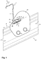
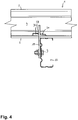
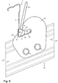
- Fig. 1 to Fig. 4 show a device which fixes a rail 1 with z-shaped cross-section on a mounting rail 60 .
- the rail 1 crosses the support rail 60 and extends with respect to gravity above this.
- Both the rail 1 and the support rail 60 are made of a steel roll-formed rails.
- the support rail 60 is not shown in detail fixed and inclined longitudinally.
- the rail 1 has a lower mounting flange 2 and an upper mounting flange 3 , which run parallel to one another here. Between the mounting flanges 2 and 3 extends diagonally a central web 4, by means of which the mounting flanges 2 and 3 are integrally connected.
- the mounting flanges 2 and 3 and the central web 4 are similar in cross-section substantially the shape of a Z.
- the device has a holding plate 10 .
- the consisting of a flat steel plate holding plate 10 is fixed to a vertical outside of the support rail 60 by means of two screws 9 .
- the retaining plate 2 extends parallel to the mounting rail 60 and is vertically aligned.
- the holding plate 10 includes an incision 11 with a front opening 12.
- the incision 11 penetrates the holding plate 10 in the plane according to Fig. 1 completely and has a first edge portion 14, a second edge portion 15 and a third Edge section 16 on.
- the first edge portion 14 and the second edge portion 15 are parallel to each other and parallel to the support rail 60th
- the rail 1 is inserted by means of its mounting flange 2 in the incision and penetrates this crossing the retaining plate 10.
- the rail 1 protrudes through the end opening 12 of the incision.
- the recess 11 surrounds the mounting flange almost completely in a c-shaped manner.
- the lower mounting flange 2 supports with its lower side on the first edge portion 14. It can be seen that the first edge portion 14 and the second edge portion 15 are arranged on different sides of the mounting flange 2 and therefore as previously mentioned face each other.
- the device also comprises a tensioning means, which in this embodiment is designed as a wedge 30 and can also be referred to as a wedge body.
- the wedge 30 spreads when driving between the upper side of the mounting flange 2 and the second edge portion 15 and presses in this way the mounting flange 2 against the first edge portion 14.
- the wedge 30 is this driven parallel to the rail 1 , for example with a hammer or a pliers.
- the wedge 30 has a wedge surface 31 . At the wedge surface 31 is adjacent to a latching recess 32 . This detent recess 32 cooperates with the second edge portion 15 . By locking the second edge portion 15 in the locking recess 32 of the wedge 30 is securely held in an end position, and it is always generated in the context of shape tolerances equal clamping force.
- the latch recess 32 is provided in the driving direction approximately centrally on the wedge 30 so that the second edge portion 15 approximately centrally loads the wedge 30 in the locked state and the pressure is distributed evenly to the mounting flange. 2
- the wedge 30 has a stop 33 .
- the stop 33 is adjacent to the locking recess 32 opposite the wedge surface 31 .
- the stop 33 blocks a driving of the wedge 30 beyond the locking recess 32 addition.
- the wedge 30 is executed in this embodiment as a deep-drawn part and hollow inside and open on the not visible in the drawings back.
- the third edge portion 16 acts as a stop, which is an extrusion of the rail 1 from the recess 11 in a direction 18 parallel to the first
- Edge section 14 blocked.
- the third edge portion 16 the rail 1 with respect to the second edge portion 15 partially overlaps.
- the third edge portion 16 lies approximately parallel to the central web 4 .
- a relative to the second edge portion 15 vertical lifting 8 of the rail 1 is blocked.
- the holding plate 2 can be seen in the region of the third edge portion 16 as a nose.
- the recess 11 has a stop 17 which positively locks a movement of the wedge 30 away from the end opening or deeper into the recess 11 blocked. Since the wedge 30 is present with a straight side edge at the round corner region between the mounting flange 2 and the central web 4 is secured by means of the wedge 30 and the rail 1 against such slipping.
- a stiffening bead 7 engages in the mounting flange 2 formcorresponding in a recess 35 on the underside of the wedge 30 .
- the first edge portion 14 has a survey, which engages for securing the position in the stiffening bead 7 .
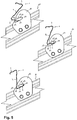
- Fig. 5 is apparent from a sequence that the incision 11 is tuned to the mounting flange 2 such that the rail 1 can be introduced with the lower mounting flange 2 frontally through the end opening 12 in the recess 11 , and only with a combined pivoting and pushing movement ,
- an insertion bevel 19 is provided in a region from the outside to the end opening 12 .
- the insertion bevel 19 and the third edge portion 16 together form a nose shape.
- the wedge 30 is in accordance with Fig. 6 placed on the mounting flange 2 and driven with a pushing movement 34 between the lower mounting flange 2 and the second edge portion 15 .
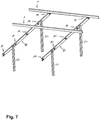
- Fig. 7 shows a typical application of the device in a mounting frame for solar systems.
- Several supports 61 each carry an inclined support rail 60.
- two rails 1 are arranged with a Z-shaped cross-section.
- the upper the rails 1 is as previously fastened to the support rails 60 by means of two devices.
- the lower of the rail 1 rests still unpaved on the support rails 60.
- the support plates 2 may be pre-assembled to the support rails 60 before delivery to the erection of the mounting frame.
- Fig. 8 and Fig. 9 show an alternative to the invention contributing alternative embodiment of the device in which the screw-free clamping means is designed as an eccentric 40 .
- the first edge portion 14 'of the incision 11 has for securing the position of the rail 1 a survey 18auf, which engages in a stiffening bead 7 in the lower mounting flange 2 of the rail 1 .
- a second edge portion 15' is arranged obliquely.
- the eccentric 40 is actuated by means of a lever 41 and can be made of an untensioned condition in accordance with Fig. 8 in a tensioned state according to Fig. 9 be transferred.
- the eccentric 40 is in this case rotatably mounted in the round corner region between the lower mounting flange 2 and the central web 4 and slides during actuation on the second edge portion 15 '.
- the second edge portion 15 ' is approximately centrally to the axis of rotation of the eccentric 40.
- the second edge portion 15' also has a latching recess 42 .
- the eccentric 40 presses the round corner area against the third edge section 16 ' and also the fastening flange 2 against the edge section 14'. Since the rail 1 is overlapped by the third edge portion 16 , as in the previous embodiment, the rail 1 is positively locked against lifting forces with respect to the first edge portion 14 ' . According to Fig.
- the eccentric 40 is in the end position on the central web 4 , which thereby acts as an end stop.
- the eccentric 40 may advantageously be designed as an extruded part and a bore for loose insertion of the lever 41 included.
- the recess 11 may be designed so that the mounting flange 2, preferably at its outermost edge, additionally opposite the first edge portion 14 ' at the incision 11th is applied.
- Fig. 10 and Fig. 11 show a further contributing to understanding the invention embodiment of the device in which the screw-free clamping means again acts by means of an eccentric 50 .
- the eccentric 50 is rotatably mounted on a support body 51 , which is part of the screw-free clamping means and rests on the mounting flange 2 in a secured position.
- the eccentric 50 can be actuated by means of a lever, not shown here, and can from an untensioned state according to Fig. 10 in a tensioned state according to Fig. 11 be transferred.
- the second edge portion 15" further comprises a locking recess 53.
- the eccentric 50 and the support body 51 may advantageously be designed as extruded part.
- the eccentric 50 may include a bore for loose insertion of the lever 53 .
Landscapes
- Engineering & Computer Science (AREA)
- General Engineering & Computer Science (AREA)
- Mechanical Engineering (AREA)
- Architecture (AREA)
- Physics & Mathematics (AREA)
- Combustion & Propulsion (AREA)
- Life Sciences & Earth Sciences (AREA)
- Sustainable Development (AREA)
- Sustainable Energy (AREA)
- Thermal Sciences (AREA)
- Chemical & Material Sciences (AREA)
- Structural Engineering (AREA)
- Civil Engineering (AREA)
- Electromagnetism (AREA)
- Clamps And Clips (AREA)
- Mutual Connection Of Rods And Tubes (AREA)
- Joining Of Building Structures In Genera (AREA)
Description
- Die Erfindung betrifft eine Vorrichtung zum Befestigen einer Schiene, insbesondere einer rollgeformten Schiene mit z-förmigem Querschnitt.
- Aus
EP 0 391 048 A2 ist eine Vorrichtung zum Befestigen einer aus Stahl rollgeformte Schiene mit z-förmigem Querschnitt bekannt. Die Schiene ist an ihrem diagonalen Mittelsteg mit der Vorrichtung verschraubt. - Aus
FR 2 572 112 A1 - Es ist eine Aufgabe der Erfindung, eine Vorrichtung der eingangs genannten Art zu schaffen, an der die Schiene einfach, schnell und sicher zu montieren ist. Die Befestigung mittels der Vorrichtung soll hoch belastbar sein. Außerdem soll die Vorrichtung besonders einfach zu fertigen sein.
- Die Aufgabe wird mit der in Anspruch 1 angegebenen Vorrichtung gelöst. Demgemäß ist die Vorrichtung zum Befestigen einer Schiene, insbesondere einer rollgeformten Schiene mit z-förmigem Querschnitt vorgesehen, wobei die Schiene einen Befestigungsflansch aufweist. Die Vorrichtung umfasst eine Halteplatte. Die Halteplatte enthält einen Einschnitt mit einer Stirnöffnung. Wesentlich ist weiter, dass die Schiene mittels des Befestigungsflanschs in den Einschnitt eingesetzt ist und hierbei die Halteplatte kreuzend durchdringt und die Schiene durch die Stirnöffnung aus dem Einschnitt herausragt. Der Einschnitt weist einen ersten Randabschnitt, einen zweiten Randabschnitt und einen dritten Randabschnitt auf, wobei der der zweite Randabschnitt dem ersten Randabschnitt gegenübersteht und der Befestigungsflansch auf dem ersten Randabschnitt lagert. Besonders charakteristisch ist, dass ein schraubenfreies Spannmittel vorgesehen ist, das sich zwischen den Befestigungsflansch und den zweiten Randabschnitt spreizt und dadurch den Befestigungsflansch gegen den ersten Randabschnitt presst. Wesentlich ist außerdem, dass der dritte Randabschnitt als Anschlag wirkt, der ein Ausdringen der Schiene aus dem Einschnitt in einer Richtung parallel zu dem ersten Randabschnitt blockiert.
- Aus rollgeformtem bzw. kaltgewalztem Band- oder Flachstahl gefertigte Schienen verfügen häufig nicht über hinterschnittene Befestigungsnuten oder geeignete Befestigungsränder, weshalb diese nicht ohne Weiteres schraubenfrei befestigbar sind. Dies gilt besonders für Schienen mit z-förmigem Querschnitt.
- Mittels der erfindungsgemäßen Vorrichtung können solche Schienen montagefreundlich und dennoch sehr stabil befestigt werden. Die Vorrichtung ist dabei bauteilarm und fertigungsgerecht herstellbar. So kann die Vorrichtung aus nur zwei einfach herzustellenden Komponenten bestehen: der Halteplatte mit dem integrierten Einschnitt sowie dem schraubenfreien Spannmittel.
- Das schraubenfreie Spannmittel ist ein Keil, der zwischen den Befestigungsflansch der Schiene und den zweiten Randabschnitt des Einschnitts mit einer Translationsbewegung eingetrieben werden kann. Ein solcher Keil kann fertigungsgerecht zum Beispiel als Strangpressteil oder bevorzugt als Tiefziehteil hergestellt sein.
- Die Halteplatte ist vorzugsweise einstückig, integral geformt und/oder metallen. Sie kann beispielsweise ein einfaches Stanzteil aus Stahl sein. Die Halteplatte ist bevorzugt eben oder planparallel ausführt. Insbesondere kann die Halteplatte eine Stahlplatte mit einer Stärke von wenigen Millimetern sein. Der Einschnitt kann durch übliche Verfahren wie Stanzen oder Schneiden aus der Halteplatte ausgenommen werden. Der Einschnitt unterbricht an einer Stelle den Schmalrand bzw. die Außenkontur der Halteplatte durch eine Stirnöffnung. Der Einschnitt ist in der Ebene der Halteplatte bevorzugt aber nicht notwendig tiefer als breit und kann daher auch allgemein als Ausnehmung mit einer Stirnöffnung bezeichnet werden.
- Die Halteplatte kann ortsfest an einem tragenden Bauteil angeordnet sein, beispielsweise an einer Stütze oder einer Tragschiene. Die Art der Befestigung der Halteplatte mit dem tragenden Bauteil kann beispielsweise eine Schweiß-, Schraub-, Niet- oder Klemmverbindung sein.
- Die Vorrichtung eignet sich besonders aber nicht nur für Schienen, die aus rollgeformten Stahl gefertigt sind und/oder einen z-förmigen Querschnitt aufweisen. Ein z-förmiger Querschnitt ist durch zwei bevorzugt parallele Flansche, einem oberen und einem unteren, gekennzeichnet, die durch einen dazu diagonalen Mittelsteg integral verbunden sind. Ein solcher z-förmiger Querschnitt ähnelt oder gleicht einem Buchstaben Z.
- Der Befestigungsflansch ist integraler Bestandteil der Schiene und vorzugsweise längs durchgehend, das heißt nicht unterbrochen. Andere Begriffe für den Befestigungsflansch können Befestigungsstreifen, -steg oder -gurt sein. Im Falle eines z-förmigen Querschnitts kann der Befestigungsflansch einer von den zwei parallelen Flanschen sein, bevorzugt der bezüglich der Schwerkraft untere, sodass die Schiene schwerkraftbedingt in der Vorrichtung lagern kann. Eine hängende Anordnung, bei der die Schiene in der Vorrichtung hängt, ist ebenso denkbar.
- Die Montage der Schiene an der Vorrichtung gestaltet sich sehr einfach: Nach Einführen und ggf. Positionieren der Schiene in die Halteplatte, das heißt genauer in den Einschnitt der Halteplatte, wird das schraubenfreie Spannmittel zwischen Befestigungsflansch und zweitem Randabschnitt eingetrieben. Beim Eintreiben spreizt sich das schraubenfreie Spannmittel zwischen den Befestigungsflansch und den zweiten Randabschnitt.
- Ein weiterer Montagevorteil ergibt sich dadurch, dass die Schiene in der Halteplatte bereits vor dem Eintreiben und sogar noch vor einem etwaigen Einsetzen des schraubenfreien Spannmittels mittels des als Anschlag wirkenden dritten Randabschnitts provisorisch in der Weise gehalten wird, dass ein Ausdringen oder Herausrutschen des Befestigungsflansches aus der Stirnöffnung des Einschnitts in einer zum ersten Randabschnitt parallelen Richtung blockiert wird. Dies ist besonders dann vorteilhaft, wenn die Halteplatte dergestalt ortsfest befestigt ist, dass der erste Randabschnitt zur Stirnöffnung hin abschüssig orientiert ist. Eine solche Orientierung tritt häufig im Zusammenhang mit der Schrägmontage von Solarmodulen auf. Vorzugsweise ist der Einschnitt in Art eines offenen Schlitzes so schmal, dass die Schiene bei einer Drehung um einen Drehpunkt im Bereich des dritten Randabschnitts nicht aus dem Einschnitt herauskippen kann.
- Das Spannmittel wirkt mittels eines Keils. Das Spannmittel kann dazu aus genau einem Keil bestehen. Dieser kann zwischen den Befestigungsflansch und den zweiten Randabschnitt eingetrieben sein, beispielsweise mittels einem Hammer, einer Zange oder einer maschinellen Eintreibeinrichtung. Die Eintreibrichtung ist bevorzugt parallel zur Schiene. Zur einfacheren Montage und/oder zur besseren Kraftverteilung sind auch Mehrfachkeile und Kombinationen mit Platten oder anderen ebenen Körpern denkbar, die Bestandteil des schraubenfreien Spannmittels sind.
- An einer Keilfläche des Keils grenzt eine Rastvertiefung an. Eine solche Rastvertiefung kann insbesondere mit dem zweiten Randabschnitt zusammenwirken. Durch ein Einrasten des zweiten Randabschnitts in die Rastvertiefung wird der Keil sicher in einer Endstellung gehalten und es wird im Rahmen von Formtoleranzen stets eine gleiche Spannkraft erzeugt.
- An die Rastvertiefung grenzt in weiterer Folge ein Anschlag, der ein weiteres Eintreiben des Keils über die Rastvertiefung hinaus blockiert. Der Anschlag kann mit der Halteplatte im Bereich des zweiten Randabschnitts zusammenwirken.
- Um ein Verrutschen des Keils im Einschnitt zu verhindern, kann der Einschnitt einen Anschlag aufweisen, der eine Bewegung des Keils weg von der Stirnöffnung bzw. tiefer in den Einschnitt hinein blockiert.
- Das Spannmittel kann alternativ, in einer nicht erfindungsgemäßen Ausführungsform mittels einem Exzenter bzw. eines exzentrischen geformten Bauteils wirken. Ein solcher Exzenter kann mit Hilfe eines Hebels betätigt werden und auf einer zusätzlichen Stützplatte schwenkbar gelagert sein, die Bestandteil des Spannmittels ist. Zum Einrasten des Exzenters in einer Endstellung kann im zweiten Randabschnitt eine Rastvertiefung enthalten sein. Eine Drehführung am zweiten Randabschnitt und eine Rastvertiefung in der Schiene oder der optionalen Stützplatte sind ebenfalls denkbar. Um ein Drehen des Exzenters über die Rastvertiefung hinaus zu blockieren, kann ein Endanschlag vorgesehen sein. Um einer unerwünschten Bewegung des Exzenters oder eines Stützkörpers in einer Richtung weg von der Stirnöffnung bzw. tiefer in den Einschnitt hinein zu blockieren, kann eine Lagesicherung vorgesehen sein.
- Bei einem mittels eines Exzenters wirkenden Spannmittel ist es auch möglich, dass der zweite Randabschnitt eine exzentrische Form aufweist und mit einem walzenförmigen Körper zusammenwirkt. Der walzenförmige Körper stellt hierbei das Spannmittel dar und kann mittels eines Hebels betätigt werden. Der walzenförmigen Körper kann wie vorbeschrieben an der Schiene oder einem separaten Stützkörper schwenkbar gelagert sein.
- Das Spannmittel kann alternativ, in einer nicht erfindungsgemäßen Ausführungsform auch mittels eines Spreizkörpers wirken, in dem ein gesteuert aktivierbares quellfähiges Material enthalten ist. Ein solches Material kann beispielsweise ein flüssigkeitsabsorbierendes Polymer sein, das durch Zugabe einer Flüssigkeit stark an Volumen zunimmt. Es ist denkbar, die Flüssigkeit mittels einer offenbaren Kapsel an dem Spreizkörper zu integrieren. Mittels Erwärmung oder Bestromung sich volumentrisch stark erweiternde Materialien sind ebenso denkbar.
- In einer bevorzugten Ausführungsform ist vorgesehen, dass der dritte Randabschnitt die Schiene bezüglich des zweiten Randabschnitts teilweise übergreift. Dadurch wird ein bezüglich des zweiten Randabschnitts senkrechtes Abheben der Schiene blockiert. Hierbei ist es zweckmäßig, wenn der Befestigungsflansch in dem Einschnitt nicht nur kraftschlüssig, sondern auch formschlüssig gegen Verrutschen parallel zum zweiten Randabschnitt gesichert ist. Hierfür kann vorgesehen sein, dass eine Erhebung oder Vertiefung im zweiten Randabschnitt in eine Versteifungssicke des Befestigungsflansches eingreift. Außerdem ist möglich, das Spannmittel und mittels des Spanmittels wiederum die Schiene gegen ein Verrutschen parallel zum zweiten Randabschnitt zu sichern. Insbesondere kann ein Spannmittel formschlüssig an einer Versteifungssicke lagegesichert sein und dazu eine seiner Unterseite eine Eintiefung aufweisen. Ein Übergreifen der Schiene ist besonders im Fall von hohen Zugkräften vorteilhaft, die bezüglich des zweiten Randabschnitts abhebend wirken. Im Falle eines z-förmigen Querschnitts kann der dritte Randabschnitt zumindest in einem Bereich, vorzugsweise in einem Endbereich zur Stirnöffnung hin, etwa parallel an dem diagonalen Mittelsteg anliegen.
- In einer bevorzugten Ausführungsform ist der Einschnitt auf den Befestigungsflansch dergestalt abgestimmt, dass die Schiene mit dem Befestigungsflansch voran bzw. frontal durch die Stirnöffnung in den Einschnitt eingeführt werden kann. Dies erleichtert die Montage, da andernfalls die Halteplatte über eines der Längsenden der Schiene aufgeschoben oder umgekehrt die Schiene der Länge nach durch die Halteplatte bis zur gewünschten Montageposition geschoben werden muss. Zum einfacheren Einführen der Schiene kann an einem Bereich außen zur Stirnöffnung hin mindestens eine Einführschräge vorgesehen sein.
- Besonders bevorzugt ist es, wenn das Einführen der Schiene mit dem Befestigungsflansch frontal durch die Stirnöffnung des Einschnitts ausschließlich mit einer kombinierten Schwenk- und Schubbewegung erfolgen kann. Dadurch kann die Ausnehmung klein ausgeführt und die Halteplatte materialeffizient gestaltet sein. Außerdem wird ein unbeabsichtigtes Lösen der Schiene erschwert, was die Montagesicherheit zusätzlich erhöht.
- Die Vorrichtung eignet sich besonders für Schienen mit z-förmigem Querschnitt. Ein solcher Querschnitt ist durch einen weiteren Befestigungsflansch gekennzeichnet, wobei die zwei Befestigungsflansche bevorzugt parallel zueinander verlaufen und diagonal mittels eines Mittelstegs integral verbunden sind.
- Die Erfindung betrifft auch eine Schienenkreuzverbindung nach Anspruch 4, umfassend die vorbeschriebene Vorrichtung, wobei eine Tragschiene vorgesehen ist, welche die Schiene kreuzt und an der die Halteplatte befestigt ist. Die Halteplatte ist bevorzugt parallel zur Tragschiene und nur an einer Seite derselben angeordnet. Die Tragschiene kann ortsfest angeordnet und längsgeneigt sein, wobei die Schiene bevorzugt über der Tragschiene verläuft und die Halteplatte vertikal orientiert ist. Bei einer solchen Schienenkreuzverbindung verläuft der zweite Randabschnitt bevorzugt parallel zur Tragschiene.
- Die Erfindung betrifft auch ein Verfahren zum Erstellen der vorbeschriebenen Schienenkreuzverbindung. Ein solches Verfahren weist folgende wesentliche Schritte auf: a) Befestigen der Halteplatte an der Tragschiene, b) Einführen der Schiene, sodass der Befestigungsflansch auf dem ersten Randabschnitt lagert, c) Positionieren des schraubenfreien Spannmittels zwischen dem Befestigungsflansch und dem zweiten Randabschnitt und d) Betätigen des schraubenfreien Spannmittels.
- Es erlaubt einen hohen Vormontagegrad, wenn zwischen Schritt a) und b) ein Verbringen der Tragschiene zusammen mit der daran befestigten Halteplatte auf eine Baustelle erfolgt, insbesondere ausgehend von einem dem letzten wesentlichen Fertigungsschritt näheren Vormontageort.
- Eine besonders angenehme Art der Montage ergibt sich, wenn der Schritt b) durch das Einführen der Schiene mit dem Befestigungsflansch frontal durch die Stirnöffnung erfolgt. Auf diese Weise wird ein Aufschieben der Haltplatte auf die Schiene oder ein Durchschieben der Schiene durch die Halteplatte über größer Längen bis zur gewünschten Befestigungsstelle vermieden.
- Nachfolgend werden Ausführungsbeispiele der Erfindung anhand von
Figuren 1-7 näher erläutert, wobeiFiguren 8-11 keine erfindungsgemäßen Vorrichtungen zeigen. Es zeigen: - Fig. 1
- eine Seitenansicht einer Vorrichtung, die eine Schiene mit z-förmigen Questschnitt mit einer Tragschiene kreuzend verbindet
- Fig. 2
- eine Perspektive der Vorrichtung gemäß
Fig. 1 - Fig. 3
- eine Perspektive der Vorrichtung gemäß
Fig. 1 - Fig. 4
- eine Rückansicht der Vorrichtung gemäß
Fig. 1 - Fig. 5
- eine Abfolge des Einführens der Schiene mit dem z-förmigen Querschnitt in die Vorrichtung gemäß
Fig. 1 - Fig. 6
- eine Perspektive der Vorrichtung gemäß
Fig. 1 im ungespannten Zustand - Fig. 7
- eine Perspektive einer Anordnung mit mehreren Vorrichtungen gemäß.
Fig. 1 - Fig. 8
- eine Seitenansicht einer Vorrichtung im ungespannten Zustand
- Fig. 9
- eine Seitenansicht der Vorrichtung gemäß
Fig. 8 im gespannten Zustand - Fig. 10
- eine Seitenansicht einer Vorrichtung im ungespannten Zustand
- Fig. 11
- eine Seitenansicht der Vorrichtung gemäß
Fig. 10 im gespannten Zustand -
Fig. 1 bis Fig. 4 zeigen eine Vorrichtung, die eine Schiene 1 mit z-förmigem Querschnitt an einer Tragschiene 60 befestigt. Die Schiene 1 kreuzt die Tragschiene 60 und verläuft bezüglich der Schwerkraft über dieser. Sowohl die Schiene 1 als auch die Tragschiene 60 sind aus einem Stahl rollgeformte Schienen. Die Tragschiene 60 ist nicht näher ersichtlich ortsfest angeordnet und längsgeneigt. - Die Schiene 1 weist einen unteren Befestigungsflansch 2 und einen oberen Befestigungsflansch 3 auf, die hier parallel zueinander verlaufen. Zwischen den Befestigungsflanschen 2 und 3 verläuft diagonal ein Mittelsteg 4, mittels dem die Befestigungsflansche 2 und 3 integral verbunden sind. Die Befestigungsflansche 2 und 3 sowie der Mittelsteg 4 gleichen im Querschnitt im Wesentlichen der Form eines Z.
- Die Vorrichtung weist eine Halteplatte 10 auf. Die aus einer ebenen Stahlplatte bestehende Halteplatte 10 ist an einer vertikalen Außenseite der Tragschiene 60 mittels zweier Schrauben 9 befestigt. Die Halteplatte 2 verläuft parallel zur Tragschiene 60 und ist vertikal ausgerichtet.
- Die Halteplatte 10 enthält einen Einschnitt 11 mit einer Stirnöffnung 12. Der Einschnitt 11 durchdringt die Halteplatte 10 in der Zeichnungsebene gemäß
Fig. 1 vollständig und weist einen ersten Randabschnitt 14, einen zweiten Randabschnitt 15 und einen dritten Randabschnitt 16 auf. Der erste Randabschnitt 14 und der zweite Randabschnitt 15 stehen einander parallel gegenüber und sind parallel zur Tragschiene 60. - Die Schiene 1 ist mittels ihres Befestigungsflanschs 2 in den Einschnitt eingesetzt und durchdringt hierbei kreuzend die Halteplatte 10. Außerdem ist zu erkennen, dass die Schiene 1 durch die Stirnöffnung 12 aus dem Einschnitt herausragt. Der Einschnitt 11 umgibt den Befestigungsflansch fast vollständig in c-förmiger Weise. Der untere Befestigungsflansch 2 lagert mit seiner unteren Seite auf dem ersten Randabschnitt 14. Zu erkennen ist, dass der ersten Randabschnitt 14 und der zweite Randabschnitt 15 auf verschiedenen Seiten des Befestigungsflansches 2 angeordnet sind und daher wie zuvor erwähnt einander gegenüberstehen.
- Die Vorrichtung weist außerdem ein Spannmittel auf, das in diesem Ausführungsbeispiel als Keil 30 ausgeführt ist und auch als Keilkörper bezeichnet werden kann. Der Keil 30 spreizt sich beim Eintreiben zwischen die obere Seite des Befestigungsflanschs 2 und dem zweiten Randabschnitt 15 und presst auf diese Weise den Befestigungsflansch 2 gegen den ersten Randabschnitt 14. Der Keil 30 wird hierzu parallel zur Schiene 1 eingetrieben, beispielsweise mit einem Hammer oder einer Zange.
- Der Keil 30 weist eine Keilfläche 31 auf. An die Keilfläche 31 grenzt eine Rastvertiefung 32 an. Diese Rastvertiefung 32 wirkt mit dem zweiten Randabschnitt 15 zusammen. Durch Einrasten des zweiten Randabschnitts 15 in die Rastvertiefung 32 wird der Keil 30 sicher in einer Endstellung gehalten, und es wird im Rahmen von Formtoleranzen stets eine gleiche Spannkraft erzeugt. Die Rastvertiefung 32 ist in Eintreibrichtung etwa mittig auf dem Keil 30 vorgesehen, sodass der zweite Randabschnitt 15 den Keil 30 im verrasteten Zustand etwa mittig belastet und der Pressdruck gleichmäßig auf den Befestigungsflansch 2 verteilt wird.
- Außerdem weist der Keil 30 einen Anschlag 33 auf. Der Anschlag 33 grenzt gegenüber der Keilfläche 31 an die Rastvertiefung 32 an. Der Anschlag 33 blockiert ein Eintreiben des Keils 30 über die Rastvertiefung 32 hinaus. Der Keil 30 ist in diesem Ausführungsbeispiel als Tiefziehteil ausgeführt und innen hohl und auf der in den Zeichnungen nicht zu erkennenden Rückseite offen.
- Wesentlich ist ferner, dass der dritte Randabschnitt 16 als Anschlag wirkt, der ein Ausdringen der Schiene 1 aus dem Einschnitt 11 in einer Richtung 18 parallel zu dem ersten
- Randabschnitt 14 blockiert. Zudem ist vorgesehen, dass der dritte Randabschnitt 16 die Schiene 1 bezüglich des zweiten Randabschnitts 15 teilweise übergreift. Der dritte Randabschnitt 16 liegt dazu etwa parallel an dem Mittelsteg 4 an. Dadurch wird ein bezüglich des zweiten Randabschnitts 15 senkrechtes Abheben 8 der Schiene 1 blockiert. Auf diese Weise können besonders hohe Zugkräfte auf die Schiene 1 wirken, ohne dass sich die Schiene 1 aus der Vorrichtung lösen kann. Die Halteplatte 2 ist im Bereich des dritten Randabschnitts 16 als Nase zu erkennen.
- Um ein unabsichtliches Verrutschen des Keils 30 in dem Einschnitt 11 während oder nach dem Eintreiben des Keils 30 zu verhindern, weist der Einschnitt 11 einen Anschlag 17 auf, der eine Bewegung des Keils 30 weg von der Stirnöffnung bzw. tiefer in den Einschnitt 11 hinein formschlüssig blockiert. Da der Keil 30 mit einer geraden Seitenkante an dem runden Eckbereich zwischen dem Befestigungsflansch 2 und dem Mittelsteg 4 ansteht ist mittels des Keils 30 auch die Schiene 1 gegen ein solches Verrutschen gesichert. Zur Lagersicherung der Schiene 1 mittels des Keils 30 ist außerdem vorgesehen, dass eine Versteifungssicke 7 im Befestigungsflansch 2 formkorrespondierend in eine Eintiefung 35 an der Unterseite des Keils 30 eingreift. Außerdem kann vorgesehen sein, dass der erste Randabschnitt 14 eine Erhebung aufweist, die zur Lagesicherung in die Versteifungssicke 7 eingreift.
- Aus
Fig. 5 ist anhand einer Abfolge ersichtlich, dass der Einschnitt 11 dergestalt auf den Befestigungsflansch 2 abgestimmt ist, dass die Schiene 1 mit dem unteren Befestigungsflansch 2 frontal durch die Stirnöffnung 12 in den Einschnitt 11 eingeführt werden kann, und zwar ausschließlich mit einer kombinierten Schwenk- und Schubbewegung. Zum einfacheren Einführen der Schiene 1 mit dem unteren Befestigungsflansch 2 voran ist in einem Bereich von außen zur Stirnöffnung 12 hin eine Einführschräge 19 vorgesehen. Die Einführschräge 19 und der dritte Randabschnitt 16 bilden zusammen eine Nasenform. In der Endstellung liegt die Schiene aufgrund ihrer Hangabtriebskraft an dem dritten Randabschnitt 16 an. In einem letzten Montageschritt wird der Keil 30 gemäßFig. 6 auf den Befestigungsflansch 2 aufgelegt und mit einer Schubbewegung 34 zwischen den unteren Befestigungsflansch 2 und dem zweiten Randabschnitt 15 eingetrieben. -
Fig. 7 zeigt eine typische Anwendung der Vorrichtung in einem Montagegestell für Solaranlagen. Mehrere Stützen 61 tragen jeweils eine schräge Tragschiene 60. Über den Tragschienen 60 sind zwei Schienen 1 mit z-förmigem Querschnitt angeordnet. Die obere der Schienen 1 ist wie zuvor mit den Tragschienen 60 mittels zweier Vorrichtungen befestigt. Die untere der Schiene 1 ruht noch unbefestigt auf den Tragschienen 60. Die Halteplatten 2 können an den Tragschienen 60 bereits vor Anlieferung zum Errichtungsort des Montagegestells vormontiert sein. -
Fig. 8 undFig. 9 zeigen eine zum Verständnis der Erfindung beitragende alternative Ausführungsform der Vorrichtung bei der das schraubenfreie Spannmittel als Exzenter 40 ausgeführt ist. Für gleiche Bauteile bezüglich des vorherigen Ausführungsbeispiels gelten die vorstehenden Ausführungen und Bezugszeichen entsprechend. Der erste Randabschnitt 14' des Einschnitts 11weist zur Lagesicherung der Schiene 1 eine Erhebung 18auf, die in eine Versteifungssicke 7 im unteren Befestigungsflansch 2 der Schiene 1 eingreift. Gegenüber dem ersten Randabschnitt 14' ist ein zweiter Randabschnitt 15' schräg angeordnet. Der Exzenter 40 wird mittels eines Hebels 41 betätigt und kann aus einen ungespannten Zustand gemäßFig. 8 in einen gespannten Zustand gemäßFig. 9 überführt werden. Der Exzenter 40 ist hierbei in dem runden Eckbereich zwischen dem unteren Befestigungsflansch 2 und dem Mittelsteg 4 drehgelagert und gleitet während der Betätigung auf dem zweiten Randabschnitt 15'. Der zweite Randabschnitt 15' ist etwa zentrisch zur Drehachse des Exzenters 40. Zum Einrasten des Exzenters 40 in einer Endstellung im gespannten Zustand weist der zweiten Randabschnitt 15' außerdem eine Rastvertiefung 42 auf. Im gespannten Zustand presst der Exzenter 40 den runden Eckbereich gegen den dritten Randabschnitt 16' und auch den Befestigungsflansch 2 gegen den Randabschnitt 14'. Da die Schiene 1 wie beim vorherigen Ausführungsbeispiel vom dritten Randabschnitt 16 übergriffen wird, ist die Schiene 1 gegen bezüglich dem ersten Randabschnitt 14' abhebende Kräfte formschlüssig blockiert. GemäßFig. 9 liegt der Exzenter 40 in der Endstellung an dem Mittelsteg 4 an, der dadurch als Endanschlag wirkt. Der Exzenter 40 kann vorteilhaft als Strangpressteil ausgeführt sein und eine Bohrung zum losen Einstecken des Hebels 41 enthalten. Um ein unbeabsichtigtes Verdrehen der Schiene 1, das heißt ein Kippen des Befestigungsflanschs 2 im Einschnitt 11 zu blockieren, kann der Einschnitt 11 so ausgeführt sein, dass der Befestigungsflansch 2, vorzugsweise an seinem äußersten Rand, zusätzlich gegenüberliegend dem ersten Randabschnitt 14' am Einschnitt 11 anliegt. Schließlich sei angemerkt, dass die Lagesicherung der Schiene 1 mittels der Erhebung 18 auch bei dem vorhergehenden Ausführungsbeispiels von Vorteil sein kann. -
Fig. 10 undFig. 11 zeigen eine weitere zum Verständnis der Erfindung beitragende Ausführungsform der Vorrichtung bei der das schraubenfreie Spannmittel wieder mittels eines Exzenters 50 wirkt. Für gleiche Bauteile gelten die vorstehenden Ausführungen und Bezugszeichen entsprechend. Gegenüber dem ersten Randabschnitt 14" des Einschnitts 10 ist ein zweiter Randabschnitt 15" angeordnet. Der Exzenter 50 ist auf einem Stützkörper 51 drehgelagert, der Bestandteil des schraubenfreien Spannmittels ist und auf dem Befestigungsflansch 2 lagegesichert aufliegt. Der Exzenter 50 kann mittels eines hier nicht gezeigten Hebels betätigt und kann aus einem ungespannten Zustand gemäßFig. 10 in einen gespannten Zustand gemäßFig. 11 überführt werden. Während der Betätigung des Exzenters 50 gleitet diese auf dem zweiten Randabschnitt 15". Zum Einrasten des Exzenters 50 in einer Endstellung im gespannten Zustand weist der zweite Randabschnitt 15" außerdem eine Rastvertiefung 53 auf. Im gespannten Zustand presst den Exzenter 50 den Befestigungsflansch 2 mittels des Stützkörpers 51 gegen den ersten Randabschnitt 14". Da die Schiene 1 wie bei den vorherigen Ausführungsbeispielen vom dritten Randabschnitt 16 übergriffen wird, ist die Schiene 1 gegen bezüglich dem ersten Randabschnitt 14" abhebende Kräfte formschlüssig blockiert. Der Exzenter 50 und der Stützkörper 51 können vorteilhaft als Strangpressteil ausgeführt sein. Der Exzenter 50 kann eine Bohrung zum losen Einstecken des Hebels 53 enthalten.
Claims (12)
- Vorrichtung zum Befestigen einer Schiene (1), insbesondere einer rollgeformten Schiene mit z-förmigem Querschnitt, wobei die Schiene (1) einen Befestigungsflansch (2) aufweist, wobei die Vorrichtung eine Halteplatte (10) umfasst und die Halteplatte (10) einen Einschnitt (11) mit einer Stirnöffnung (12) enthält, wobei der Einschnitt (11) derart ausgebildet ist, dass die Schiene (1) mittels des Befestigungsflanschs (2) in den Einschnitt (11) einsetzbar ist, wobei die Schiene (11) die Halteplatte (1) kreuzend durchdringt und die Schiene (1) durch die Stirnöffnung (12) aus dem Einschnitt (11) herausragt, und der Einschnitt (11) einen ersten Randabschnitt (14), einen zweiten Randabschnitt (15) und einen dritten Randabschnitt (16) aufweist, und der zweite Randabschnitt (15) dem ersten Randabschnitt (14) gegenübersteht, und der Befestigungsflansch (2) auf dem ersten Randabschnitt (14) lagerbar ist, und wobei die Vorrichtung ein schraubenfreies Spannmittel (30; 40; 50, 51) umfasst, das vorgesehen ist, sich zwischen den Befestigungsflansch (2) und den zweiten Randabschnitt (15) zu spreizen und dazu geeignet ist, den Befestigungsflansch (2) gegen den ersten Randabschnitt (14) zu pressen, und der dritte Randabschnitt (16) als Anschlag wirkt, der dazu ausgebildet ist, ein Ausdringen der Schiene (1) aus dem Einschnitt (11) in einer Richtung (18) parallel zu dem ersten Randabschnitt (14) zu blockieren, wobei das schraubenfreie Spannmittel mittels eines Keils (30) wirkt, der eine Keilfläche (31) aufweist, an die eine Rastvertiefung (32) grenzt, dadurch gekennzeichnet, dass an die Rastvertiefung (32) ein Anschlag (33) angrenzt, der ein weiteres Eintreiben des Keils (30) blockiert, wobei der Anschlag (33) mit der Halteplatte (10) vorzugsweise im Bereich des zweiten Randabschnitts (15) zusammenwirkt.
- Vorrichtung nach Anspruch 1, dadurch gekennzeichnet, dass der Einschnitt (11) einen Anschlag (17) aufweist, der eine Bewegung des Keils (30) weg von der Stirnöffnung (12) blockiert.
- Vorrichtung nach einem der vorhergehenden Ansprüche, dadurch gekennzeichnet, dass der dritte Randabschnitt (16) dazu vorgesehen ist, die Schiene (1) bezüglich des ersten Randabschnitts (14) teilweise zu übergreifen.
- Schienenkreuzverbindung mit einer Vorrichtung nach einem der vorhergehenden Ansprüche, dadurch gekennzeichnet, dass eine Tragschiene (60) vorgesehen ist, welche die Schiene (1) kreuzt und an der die Halteplatte (10) befestigt ist.
- Schienenkreuzverbindung nach Anspruch 4, dadurch gekennzeichnet, dass der Einschnitt (11) auf den Befestigungsflansch (2) dergestalt abgestimmt ist, dass die Schiene (1) mit dem Befestigungsflansch (2) frontal durch die Stirnöffnung (12) in den Einschnitt (11) eingeführt werden kann.
- Schienenkreuzverbindung nach Anspruch 4 oder 5, dadurch gekennzeichnet, dass der Einschnitt (11) auf den Befestigungsflansch (2) dergestalt abgestimmt ist, dass die Schiene (1) mit dem Befestigungsflansch (2) frontal durch die Stirnöffnung (12) in den Einschnitt (11) ausschließlich mit einer kombinierten Schwenk- und Schubbewegung eingeführt werden kann.
- Schienenkreuzverbindung nach einem der Ansprüche 4 bis 6, dadurch gekennzeichnet, dass der zweite Randabschnitt (15) parallel zur Tragschiene (60) verläuft.
- Verfahren zum Erstellen der Schienenkreuzverbindung nach einem der Ansprüche 4 bis 7 mit der Vorrichtung nach einem der Ansprüche 1 bis 3 und mit den Schritten:a) Befestigen der Halteplatte (10) an der Tragschiene (60),b) Einführen der Schiene (1), sodass der Befestigungsflansch (2) den Einschnitt (11) kreuzt, und Absetzen der Schiene (1), sodass der Befestigungsflansch (2) auf dem ersten Randabschnitt (14) lagert,c) Positionieren des Keils (30) zwischen dem Befestigungsflansch (2) und dem zweiten Randabschnitt (15), undd) Eintreiben des Keils (30) bis zum Anschlag (33).
- Verfahren nach Anspruch 8, dadurch gekennzeichnet, dass zwischen Schritt a) und Schritt b) ein Verbringen der Tragschiene (60) und der Halteplatte (10) auf eine Baustelle erfolgt.
- Verfahren nach Anspruch 8 oder 9, dadurch gekennzeichnet, dass der Schritt b) durch das Einführen der Schiene (1) mit dem Befestigungsflansch (2) frontal durch die Stirnöffnung (12) erfolgt.
- Verfahren nach Anspruch 10, dadurch gekennzeichnet, dass das Einführen der Schiene (1) durch eine kombinierte Schwenk- und Schubbewegung erfolgt.
- Verfahren nach einem der Ansprüche 8 bis 11, dadurch gekennzeichnet, dass während oder nach dem Absetzen die Schiene (1) an dem dritten Randabschnitt (16) angelegt wird oder dort selbst schwerkraftbedingt anschlägt.
Priority Applications (1)
| Application Number | Priority Date | Filing Date | Title |
|---|---|---|---|
| PL13727025T PL2823113T3 (pl) | 2012-03-06 | 2013-03-06 | Urządzenie do mocowania szyny |
Applications Claiming Priority (2)
| Application Number | Priority Date | Filing Date | Title |
|---|---|---|---|
| DE202012002174U DE202012002174U1 (de) | 2012-03-06 | 2012-03-06 | Vorrichtung zum Befestigen einer Schiene |
| PCT/DE2013/000119 WO2013131509A1 (de) | 2012-03-06 | 2013-03-06 | Vorrichtung zum befestigen einer schiene |
Publications (2)
| Publication Number | Publication Date |
|---|---|
| EP2823113A1 EP2823113A1 (de) | 2015-01-14 |
| EP2823113B1 true EP2823113B1 (de) | 2018-09-19 |
Family
ID=48576662
Family Applications (1)
| Application Number | Title | Priority Date | Filing Date |
|---|---|---|---|
| EP13727025.2A Active EP2823113B1 (de) | 2012-03-06 | 2013-03-06 | Vorrichtung zum befestigen einer schiene |
Country Status (7)
| Country | Link |
|---|---|
| US (1) | US9506238B2 (de) |
| EP (1) | EP2823113B1 (de) |
| JP (1) | JP6320305B2 (de) |
| DE (2) | DE202012002174U1 (de) |
| ES (1) | ES2692192T3 (de) |
| PL (1) | PL2823113T3 (de) |
| WO (1) | WO2013131509A1 (de) |
Families Citing this family (6)
| Publication number | Priority date | Publication date | Assignee | Title |
|---|---|---|---|---|
| CN104753449B (zh) * | 2013-12-31 | 2017-08-22 | 比亚迪股份有限公司 | 安装块、太阳能电池组件和太阳能光伏电站系统 |
| GB2526269B (en) * | 2014-05-16 | 2018-09-12 | Solar Frame Solutions Ltd | Solar-collector roofing assembly |
| AU2014101408B4 (en) * | 2014-10-14 | 2015-04-30 | Michael Smith | Integrated modular metal frame building system |
| DE102018001170A1 (de) * | 2017-02-24 | 2018-08-30 | Erhan Dinçer | Verbindungssystem für sich kreuzende Profile mit einstellbaren Verbindungselementen, Solaranlage, Freiflächenanlage, Dach, Carport mit dem System der Hebeschiebetechnik |
| AT525572B1 (de) * | 2022-02-15 | 2023-05-15 | Julius Fritsche Gmbh | Solaranlage mit positionierleiste |
| EP4566164A1 (de) * | 2023-02-07 | 2025-06-11 | Pegasus Solar Inc. | Kippbeinsystem für solarpaneelanordnungen |
Family Cites Families (16)
| Publication number | Priority date | Publication date | Assignee | Title |
|---|---|---|---|---|
| US1332442A (en) * | 1919-07-21 | 1920-03-02 | Thomas H Kane | Clamp |
| JPS6021011U (ja) * | 1983-07-21 | 1985-02-13 | 新日本化成株式会社 | 金網フレ−ムの連結固定具 |
| FR2572112B1 (fr) | 1984-10-24 | 1988-06-24 | Nicoll Raccords Plastiques | Etrier pour crochet de gouttiere d'eaux pluviales |
| JPH01137003A (ja) * | 1987-11-25 | 1989-05-30 | Buruman Kk | 仮設軌条締結方法及びその装置 |
| DE3934332A1 (de) | 1989-04-04 | 1991-04-18 | Gerd Peter | Stahlbaukonstruktion fuer ein hochregallager |
| DK170106B1 (da) | 1992-02-07 | 1995-05-29 | Carl Cilius Rosenvinge | Holder til tekstilkant |
| JPH05340786A (ja) * | 1992-06-11 | 1993-12-21 | Fuji Electric Co Ltd | 液面検出スイッチ |
| US5692272A (en) * | 1996-12-16 | 1997-12-02 | Woods; Lydia A. | Clip for gripping sheet material |
| US6622980B2 (en) * | 2000-03-28 | 2003-09-23 | Hill-Rom Services, Inc. | Socket and rail clamp apparatus |
| US7004943B2 (en) * | 2002-02-04 | 2006-02-28 | Smith & Nephew, Inc. | Devices, systems, and methods for placing and positioning fixation elements in external fixation systems |
| JP4255122B2 (ja) * | 2003-12-11 | 2009-04-15 | 東都興業株式会社 | ジョイント |
| US7636986B2 (en) * | 2005-02-03 | 2009-12-29 | Nite Ize, Inc. | Tensioning device |
| US7992752B2 (en) * | 2005-06-30 | 2011-08-09 | Blanking Systems, Inc. | Blanking tool and a method of assembling the blanking tool |
| US20070258755A1 (en) * | 2006-05-04 | 2007-11-08 | Chien-Chung Chang | Framework connection set |
| US7509713B2 (en) * | 2007-03-02 | 2009-03-31 | Get A Grip, Inc. | Clamp assembly |
| US8651725B2 (en) * | 2010-09-30 | 2014-02-18 | Global Lighting Technology Inc. | Backlight module |
-
2012
- 2012-03-06 DE DE202012002174U patent/DE202012002174U1/de not_active Expired - Lifetime
-
2013
- 2013-03-06 WO PCT/DE2013/000119 patent/WO2013131509A1/de not_active Ceased
- 2013-03-06 US US14/383,107 patent/US9506238B2/en not_active Expired - Fee Related
- 2013-03-06 DE DE112013001325.8T patent/DE112013001325A5/de not_active Withdrawn
- 2013-03-06 EP EP13727025.2A patent/EP2823113B1/de active Active
- 2013-03-06 JP JP2014560248A patent/JP6320305B2/ja active Active
- 2013-03-06 PL PL13727025T patent/PL2823113T3/pl unknown
- 2013-03-06 ES ES13727025.2T patent/ES2692192T3/es active Active
Non-Patent Citations (1)
| Title |
|---|
| None * |
Also Published As
| Publication number | Publication date |
|---|---|
| US20150050074A1 (en) | 2015-02-19 |
| DE112013001325A5 (de) | 2014-11-20 |
| EP2823113A1 (de) | 2015-01-14 |
| PL2823113T3 (pl) | 2019-02-28 |
| ES2692192T3 (es) | 2018-11-30 |
| JP6320305B2 (ja) | 2018-05-09 |
| DE202012002174U1 (de) | 2013-06-12 |
| JP2015513018A (ja) | 2015-04-30 |
| US9506238B2 (en) | 2016-11-29 |
| WO2013131509A1 (de) | 2013-09-12 |
Similar Documents
| Publication | Publication Date | Title |
|---|---|---|
| DE102012017424B4 (de) | Vorrichtung für Stechschneidwerkzeug, Stechschneidplatte sowie Stechschneidwerkzeug | |
| DE102016215037B4 (de) | Federvorrichtung und Verbindungsvorrichtung | |
| EP3291706B1 (de) | Möbel und verfahren zum festlegen eines bewegbaren möbelteils | |
| EP2410190B1 (de) | Einrichtung zum Befestigen eines Gegenstands an einem eine berandete Öffnung aufweisenden Bauteil | |
| EP3472403B1 (de) | Vorrichtung zum befestigen eines plattenförmigen bauteils in einer aufnahmenut einer tragschiene | |
| EP1442942B1 (de) | Flanschverbindung zwischen einem Fahrzeuglängsträger und einem daran ansetzbaren Trägerelement | |
| DE2239370B2 (de) | Befestigungsvorrichtung mit einem Klemmverschluß zum lösbaren Eingreifen in eine Hinterschneidungen aufweisende Nut, insbesondere an Profilen | |
| WO2013131509A1 (de) | Vorrichtung zum befestigen einer schiene | |
| EP0238848A2 (de) | Befestigungsvorrichtung mit einem Klemmverschluss zum lösbaren Angreifen an Hinterschneidungen aufweisenden Profilen | |
| EP2944737B1 (de) | Spannvorrichtung zum verbinden von profilschienen | |
| DE102010054183A1 (de) | Blechanordnung und Verfahren zum Verschweißen zweier Blechteile | |
| EP1764168A1 (de) | Schieberanordnung für einen Luftnockenaufbau | |
| EP2372269A2 (de) | Verbindungsvorrichtung und Profilanordnung | |
| EP2786675A2 (de) | Positioniervorrichtung, Vorrichtung zum Bewegen eines Möbels sowie Möbel und Verfahren zur Montage eines bewegbaren Möbelteils an einer Führungseinrichtung | |
| EP0698720A1 (de) | Verfahren zum Befestigen von Eckverbindern, vorzugsweise aus verscheissbarem Kunststoff, und Eckverbinder zur Verwendung bei einem solchen Verfahren | |
| DE3616031C2 (de) | ||
| EP1167670B1 (de) | Befestigungsplatte zur Befestigung eines Scharnierarmes eines Möbelscharniers | |
| DE102011010828B4 (de) | Klemmvorrichtung zur lösbaren Befestigung eines Gerätegehäuses an einer Profilschiene | |
| EP2827043B1 (de) | Verfahren zur Herstellung einer Doppelschiene sowie Doppelschiene | |
| DE2831987C2 (de) | Verfahren zur Herstellung eines wärmeisolierenden Profilkörpers, insbesondere für Tür- oder Fensterrahmen o.dgl. | |
| WO2015074933A1 (de) | Haltevorrichtung für ein gehäuse und verfahren zur montage des gehäuses unter verwendung der haltevorrichtung | |
| WO2004101188A1 (de) | Werkzeugaufnahmevorrichtung | |
| DE29718854U1 (de) | Profilrahmen, insbesondere U-Profilrahmen zur Halterung von Flächenelementen wie Glasscheiben, Kunststoffplatten o.dgl. | |
| DE102012004210A1 (de) | Vorrichtung zum Befestigen einer Schiene | |
| EP1780345B1 (de) | Verbinder für rinnenförmige Profilstäbe und Verbindungsanordnung |
Legal Events
| Date | Code | Title | Description |
|---|---|---|---|
| PUAI | Public reference made under article 153(3) epc to a published international application that has entered the european phase |
Free format text: ORIGINAL CODE: 0009012 |
|
| 17P | Request for examination filed |
Effective date: 20141003 |
|
| AK | Designated contracting states |
Kind code of ref document: A1 Designated state(s): AL AT BE BG CH CY CZ DE DK EE ES FI FR GB GR HR HU IE IS IT LI LT LU LV MC MK MT NL NO PL PT RO RS SE SI SK SM TR |
|
| AX | Request for extension of the european patent |
Extension state: BA ME |
|
| DAX | Request for extension of the european patent (deleted) | ||
| 17Q | First examination report despatched |
Effective date: 20160405 |
|
| STAA | Information on the status of an ep patent application or granted ep patent |
Free format text: STATUS: EXAMINATION IS IN PROGRESS |
|
| GRAP | Despatch of communication of intention to grant a patent |
Free format text: ORIGINAL CODE: EPIDOSNIGR1 |
|
| STAA | Information on the status of an ep patent application or granted ep patent |
Free format text: STATUS: GRANT OF PATENT IS INTENDED |
|
| RIC1 | Information provided on ipc code assigned before grant |
Ipc: F16B 7/04 20060101ALI20180322BHEP Ipc: E04B 1/24 20060101AFI20180322BHEP |
|
| INTG | Intention to grant announced |
Effective date: 20180413 |
|
| GRAS | Grant fee paid |
Free format text: ORIGINAL CODE: EPIDOSNIGR3 |
|
| GRAA | (expected) grant |
Free format text: ORIGINAL CODE: 0009210 |
|
| STAA | Information on the status of an ep patent application or granted ep patent |
Free format text: STATUS: THE PATENT HAS BEEN GRANTED |
|
| AK | Designated contracting states |
Kind code of ref document: B1 Designated state(s): AL AT BE BG CH CY CZ DE DK EE ES FI FR GB GR HR HU IE IS IT LI LT LU LV MC MK MT NL NO PL PT RO RS SE SI SK SM TR |
|
| REG | Reference to a national code |
Ref country code: GB Ref legal event code: FG4D Free format text: NOT ENGLISH |
|
| REG | Reference to a national code |
Ref country code: CH Ref legal event code: EP |
|
| REG | Reference to a national code |
Ref country code: DE Ref legal event code: R096 Ref document number: 502013011120 Country of ref document: DE |
|
| REG | Reference to a national code |
Ref country code: AT Ref legal event code: REF Ref document number: 1043430 Country of ref document: AT Kind code of ref document: T Effective date: 20181015 |
|
| REG | Reference to a national code |
Ref country code: IE Ref legal event code: FG4D Free format text: LANGUAGE OF EP DOCUMENT: GERMAN |
|
| REG | Reference to a national code |
Ref country code: NL Ref legal event code: FP |
|
| REG | Reference to a national code |
Ref country code: ES Ref legal event code: FG2A Ref document number: 2692192 Country of ref document: ES Kind code of ref document: T3 Effective date: 20181130 |
|
| RAP2 | Party data changed (patent owner data changed or rights of a patent transferred) |
Owner name: SCHLETTER INTERNATIONAL B.V. |
|
| PG25 | Lapsed in a contracting state [announced via postgrant information from national office to epo] |
Ref country code: FI Free format text: LAPSE BECAUSE OF FAILURE TO SUBMIT A TRANSLATION OF THE DESCRIPTION OR TO PAY THE FEE WITHIN THE PRESCRIBED TIME-LIMIT Effective date: 20180919 Ref country code: GR Free format text: LAPSE BECAUSE OF FAILURE TO SUBMIT A TRANSLATION OF THE DESCRIPTION OR TO PAY THE FEE WITHIN THE PRESCRIBED TIME-LIMIT Effective date: 20181220 Ref country code: RS Free format text: LAPSE BECAUSE OF FAILURE TO SUBMIT A TRANSLATION OF THE DESCRIPTION OR TO PAY THE FEE WITHIN THE PRESCRIBED TIME-LIMIT Effective date: 20180919 Ref country code: NO Free format text: LAPSE BECAUSE OF FAILURE TO SUBMIT A TRANSLATION OF THE DESCRIPTION OR TO PAY THE FEE WITHIN THE PRESCRIBED TIME-LIMIT Effective date: 20181219 Ref country code: SE Free format text: LAPSE BECAUSE OF FAILURE TO SUBMIT A TRANSLATION OF THE DESCRIPTION OR TO PAY THE FEE WITHIN THE PRESCRIBED TIME-LIMIT Effective date: 20180919 Ref country code: BG Free format text: LAPSE BECAUSE OF FAILURE TO SUBMIT A TRANSLATION OF THE DESCRIPTION OR TO PAY THE FEE WITHIN THE PRESCRIBED TIME-LIMIT Effective date: 20181219 Ref country code: LT Free format text: LAPSE BECAUSE OF FAILURE TO SUBMIT A TRANSLATION OF THE DESCRIPTION OR TO PAY THE FEE WITHIN THE PRESCRIBED TIME-LIMIT Effective date: 20180919 |
|
| REG | Reference to a national code |
Ref country code: LT Ref legal event code: MG4D |
|
| PG25 | Lapsed in a contracting state [announced via postgrant information from national office to epo] |
Ref country code: AL Free format text: LAPSE BECAUSE OF FAILURE TO SUBMIT A TRANSLATION OF THE DESCRIPTION OR TO PAY THE FEE WITHIN THE PRESCRIBED TIME-LIMIT Effective date: 20180919 Ref country code: LV Free format text: LAPSE BECAUSE OF FAILURE TO SUBMIT A TRANSLATION OF THE DESCRIPTION OR TO PAY THE FEE WITHIN THE PRESCRIBED TIME-LIMIT Effective date: 20180919 Ref country code: HR Free format text: LAPSE BECAUSE OF FAILURE TO SUBMIT A TRANSLATION OF THE DESCRIPTION OR TO PAY THE FEE WITHIN THE PRESCRIBED TIME-LIMIT Effective date: 20180919 |
|
| PG25 | Lapsed in a contracting state [announced via postgrant information from national office to epo] |
Ref country code: IS Free format text: LAPSE BECAUSE OF FAILURE TO SUBMIT A TRANSLATION OF THE DESCRIPTION OR TO PAY THE FEE WITHIN THE PRESCRIBED TIME-LIMIT Effective date: 20190119 Ref country code: CZ Free format text: LAPSE BECAUSE OF FAILURE TO SUBMIT A TRANSLATION OF THE DESCRIPTION OR TO PAY THE FEE WITHIN THE PRESCRIBED TIME-LIMIT Effective date: 20180919 Ref country code: RO Free format text: LAPSE BECAUSE OF FAILURE TO SUBMIT A TRANSLATION OF THE DESCRIPTION OR TO PAY THE FEE WITHIN THE PRESCRIBED TIME-LIMIT Effective date: 20180919 Ref country code: EE Free format text: LAPSE BECAUSE OF FAILURE TO SUBMIT A TRANSLATION OF THE DESCRIPTION OR TO PAY THE FEE WITHIN THE PRESCRIBED TIME-LIMIT Effective date: 20180919 |
|
| REG | Reference to a national code |
Ref country code: DE Ref legal event code: R082 Ref document number: 502013011120 Country of ref document: DE Representative=s name: WUESTHOFF & WUESTHOFF, PATENTANWAELTE PARTG MB, DE Ref country code: DE Ref legal event code: R081 Ref document number: 502013011120 Country of ref document: DE Owner name: SCHLETTER INTERNATIONAL B.V., NL Free format text: FORMER OWNER: SCHLETTER GMBH, 83527 KIRCHDORF, DE |
|
| RAP2 | Party data changed (patent owner data changed or rights of a patent transferred) |
Owner name: SCHLETTER INTERNATIONAL B.V. |
|
| PG25 | Lapsed in a contracting state [announced via postgrant information from national office to epo] |
Ref country code: SM Free format text: LAPSE BECAUSE OF FAILURE TO SUBMIT A TRANSLATION OF THE DESCRIPTION OR TO PAY THE FEE WITHIN THE PRESCRIBED TIME-LIMIT Effective date: 20180919 Ref country code: SK Free format text: LAPSE BECAUSE OF FAILURE TO SUBMIT A TRANSLATION OF THE DESCRIPTION OR TO PAY THE FEE WITHIN THE PRESCRIBED TIME-LIMIT Effective date: 20180919 Ref country code: PT Free format text: LAPSE BECAUSE OF FAILURE TO SUBMIT A TRANSLATION OF THE DESCRIPTION OR TO PAY THE FEE WITHIN THE PRESCRIBED TIME-LIMIT Effective date: 20190119 |
|
| REG | Reference to a national code |
Ref country code: DE Ref legal event code: R097 Ref document number: 502013011120 Country of ref document: DE |
|
| PLBE | No opposition filed within time limit |
Free format text: ORIGINAL CODE: 0009261 |
|
| STAA | Information on the status of an ep patent application or granted ep patent |
Free format text: STATUS: NO OPPOSITION FILED WITHIN TIME LIMIT |
|
| PG25 | Lapsed in a contracting state [announced via postgrant information from national office to epo] |
Ref country code: DK Free format text: LAPSE BECAUSE OF FAILURE TO SUBMIT A TRANSLATION OF THE DESCRIPTION OR TO PAY THE FEE WITHIN THE PRESCRIBED TIME-LIMIT Effective date: 20180919 |
|
| 26N | No opposition filed |
Effective date: 20190620 |
|
| REG | Reference to a national code |
Ref country code: NL Ref legal event code: PD Owner name: SCHLETTER INTERNATIONAL B.V.; NL Free format text: DETAILS ASSIGNMENT: CHANGE OF OWNER(S), ASSIGNMENT; FORMER OWNER NAME: SCHLETTER GMBH Effective date: 20190516 |
|
| REG | Reference to a national code |
Ref country code: GB Ref legal event code: 732E Free format text: REGISTERED BETWEEN 20190815 AND 20190821 |
|
| PG25 | Lapsed in a contracting state [announced via postgrant information from national office to epo] |
Ref country code: SI Free format text: LAPSE BECAUSE OF FAILURE TO SUBMIT A TRANSLATION OF THE DESCRIPTION OR TO PAY THE FEE WITHIN THE PRESCRIBED TIME-LIMIT Effective date: 20180919 Ref country code: MC Free format text: LAPSE BECAUSE OF FAILURE TO SUBMIT A TRANSLATION OF THE DESCRIPTION OR TO PAY THE FEE WITHIN THE PRESCRIBED TIME-LIMIT Effective date: 20180919 |
|
| REG | Reference to a national code |
Ref country code: CH Ref legal event code: PL |
|
| PG25 | Lapsed in a contracting state [announced via postgrant information from national office to epo] |
Ref country code: LU Free format text: LAPSE BECAUSE OF NON-PAYMENT OF DUE FEES Effective date: 20190306 |
|
| REG | Reference to a national code |
Ref country code: BE Ref legal event code: MM Effective date: 20190331 |
|
| PG25 | Lapsed in a contracting state [announced via postgrant information from national office to epo] |
Ref country code: IE Free format text: LAPSE BECAUSE OF NON-PAYMENT OF DUE FEES Effective date: 20190306 Ref country code: LI Free format text: LAPSE BECAUSE OF NON-PAYMENT OF DUE FEES Effective date: 20190331 Ref country code: CH Free format text: LAPSE BECAUSE OF NON-PAYMENT OF DUE FEES Effective date: 20190331 |
|
| PG25 | Lapsed in a contracting state [announced via postgrant information from national office to epo] |
Ref country code: BE Free format text: LAPSE BECAUSE OF NON-PAYMENT OF DUE FEES Effective date: 20190331 |
|
| PG25 | Lapsed in a contracting state [announced via postgrant information from national office to epo] |
Ref country code: TR Free format text: LAPSE BECAUSE OF FAILURE TO SUBMIT A TRANSLATION OF THE DESCRIPTION OR TO PAY THE FEE WITHIN THE PRESCRIBED TIME-LIMIT Effective date: 20180919 |
|
| PG25 | Lapsed in a contracting state [announced via postgrant information from national office to epo] |
Ref country code: MT Free format text: LAPSE BECAUSE OF FAILURE TO SUBMIT A TRANSLATION OF THE DESCRIPTION OR TO PAY THE FEE WITHIN THE PRESCRIBED TIME-LIMIT Effective date: 20180919 |
|
| REG | Reference to a national code |
Ref country code: AT Ref legal event code: MM01 Ref document number: 1043430 Country of ref document: AT Kind code of ref document: T Effective date: 20190306 |
|
| PG25 | Lapsed in a contracting state [announced via postgrant information from national office to epo] |
Ref country code: AT Free format text: LAPSE BECAUSE OF NON-PAYMENT OF DUE FEES Effective date: 20190306 |
|
| PG25 | Lapsed in a contracting state [announced via postgrant information from national office to epo] |
Ref country code: CY Free format text: LAPSE BECAUSE OF FAILURE TO SUBMIT A TRANSLATION OF THE DESCRIPTION OR TO PAY THE FEE WITHIN THE PRESCRIBED TIME-LIMIT Effective date: 20180919 |
|
| PG25 | Lapsed in a contracting state [announced via postgrant information from national office to epo] |
Ref country code: HU Free format text: LAPSE BECAUSE OF FAILURE TO SUBMIT A TRANSLATION OF THE DESCRIPTION OR TO PAY THE FEE WITHIN THE PRESCRIBED TIME-LIMIT; INVALID AB INITIO Effective date: 20130306 |
|
| REG | Reference to a national code |
Ref country code: DE Ref legal event code: R082 Ref document number: 502013011120 Country of ref document: DE Representative=s name: THUM, MOETSCH, WEICKERT PATENTANWAELTE PARTG M, DE Ref country code: DE Ref legal event code: R082 Ref document number: 502013011120 Country of ref document: DE Representative=s name: THUM & PARTNER THUM MOETSCH WEICKERT PATENTANW, DE |
|
| PG25 | Lapsed in a contracting state [announced via postgrant information from national office to epo] |
Ref country code: MK Free format text: LAPSE BECAUSE OF FAILURE TO SUBMIT A TRANSLATION OF THE DESCRIPTION OR TO PAY THE FEE WITHIN THE PRESCRIBED TIME-LIMIT Effective date: 20180919 |
|
| P01 | Opt-out of the competence of the unified patent court (upc) registered |
Effective date: 20230525 |
|
| PGFP | Annual fee paid to national office [announced via postgrant information from national office to epo] |
Ref country code: ES Payment date: 20250416 Year of fee payment: 13 |
|
| PGFP | Annual fee paid to national office [announced via postgrant information from national office to epo] |
Ref country code: IT Payment date: 20250331 Year of fee payment: 13 |
|
| PGFP | Annual fee paid to national office [announced via postgrant information from national office to epo] |
Ref country code: GB Payment date: 20260324 Year of fee payment: 14 |
|
| PGFP | Annual fee paid to national office [announced via postgrant information from national office to epo] |
Ref country code: DE Payment date: 20260320 Year of fee payment: 14 |
|
| PGFP | Annual fee paid to national office [announced via postgrant information from national office to epo] |
Ref country code: NL Payment date: 20260323 Year of fee payment: 14 |
|
| PGFP | Annual fee paid to national office [announced via postgrant information from national office to epo] |
Ref country code: FR Payment date: 20260324 Year of fee payment: 14 |
|
| PGFP | Annual fee paid to national office [announced via postgrant information from national office to epo] |
Ref country code: PL Payment date: 20260224 Year of fee payment: 14 |