EP2822787B1 - A dynamically-supported movable downforce-generating underbody in a motor vehicle - Google Patents
A dynamically-supported movable downforce-generating underbody in a motor vehicle Download PDFInfo
- Publication number
- EP2822787B1 EP2822787B1 EP13757751.6A EP13757751A EP2822787B1 EP 2822787 B1 EP2822787 B1 EP 2822787B1 EP 13757751 A EP13757751 A EP 13757751A EP 2822787 B1 EP2822787 B1 EP 2822787B1
- Authority
- EP
- European Patent Office
- Prior art keywords
- movable underbody
- vehicle
- underbody
- movable
- motor vehicle
- Prior art date
- Legal status (The legal status is an assumption and is not a legal conclusion. Google has not performed a legal analysis and makes no representation as to the accuracy of the status listed.)
- Active
Links
- 239000000725 suspension Substances 0.000 claims description 184
- 230000006641 stabilisation Effects 0.000 claims description 151
- 238000011105 stabilization Methods 0.000 claims description 151
- 230000033001 locomotion Effects 0.000 claims description 61
- 238000006073 displacement reaction Methods 0.000 claims description 9
- 230000003028 elevating effect Effects 0.000 claims description 5
- 238000000034 method Methods 0.000 description 65
- 230000008569 process Effects 0.000 description 56
- 230000007246 mechanism Effects 0.000 description 42
- 230000000694 effects Effects 0.000 description 28
- 230000008901 benefit Effects 0.000 description 21
- 230000001133 acceleration Effects 0.000 description 19
- 238000013461 design Methods 0.000 description 19
- 239000000463 material Substances 0.000 description 15
- 230000007423 decrease Effects 0.000 description 14
- 230000006835 compression Effects 0.000 description 12
- 238000007906 compression Methods 0.000 description 12
- 229920000271 Kevlar® Polymers 0.000 description 11
- 230000001965 increasing effect Effects 0.000 description 11
- 239000004761 kevlar Substances 0.000 description 11
- 241000239290 Araneae Species 0.000 description 10
- 230000000670 limiting effect Effects 0.000 description 10
- 230000008859 change Effects 0.000 description 9
- 238000009826 distribution Methods 0.000 description 9
- 238000012546 transfer Methods 0.000 description 9
- 230000006870 function Effects 0.000 description 8
- 239000011295 pitch Substances 0.000 description 8
- 238000005452 bending Methods 0.000 description 6
- 230000003247 decreasing effect Effects 0.000 description 6
- 238000010586 diagram Methods 0.000 description 6
- 238000000926 separation method Methods 0.000 description 6
- 238000005299 abrasion Methods 0.000 description 5
- 238000001816 cooling Methods 0.000 description 5
- 238000013016 damping Methods 0.000 description 4
- 230000007935 neutral effect Effects 0.000 description 4
- 229920000049 Carbon (fiber) Polymers 0.000 description 3
- 230000000712 assembly Effects 0.000 description 3
- 238000000429 assembly Methods 0.000 description 3
- 239000004917 carbon fiber Substances 0.000 description 3
- 239000012141 concentrate Substances 0.000 description 3
- VNWKTOKETHGBQD-UHFFFAOYSA-N methane Chemical compound C VNWKTOKETHGBQD-UHFFFAOYSA-N 0.000 description 3
- 230000009467 reduction Effects 0.000 description 3
- 230000002829 reductive effect Effects 0.000 description 3
- 230000002441 reversible effect Effects 0.000 description 3
- 229910001149 41xx steel Inorganic materials 0.000 description 2
- 238000012935 Averaging Methods 0.000 description 2
- 229910000831 Steel Inorganic materials 0.000 description 2
- 230000009471 action Effects 0.000 description 2
- 229910052782 aluminium Inorganic materials 0.000 description 2
- XAGFODPZIPBFFR-UHFFFAOYSA-N aluminium Chemical compound [Al] XAGFODPZIPBFFR-UHFFFAOYSA-N 0.000 description 2
- 238000004364 calculation method Methods 0.000 description 2
- 230000008878 coupling Effects 0.000 description 2
- 238000010168 coupling process Methods 0.000 description 2
- 238000005859 coupling reaction Methods 0.000 description 2
- 239000011152 fibreglass Substances 0.000 description 2
- 238000009499 grossing Methods 0.000 description 2
- 230000014759 maintenance of location Effects 0.000 description 2
- 230000004044 response Effects 0.000 description 2
- 230000000284 resting effect Effects 0.000 description 2
- 230000003068 static effect Effects 0.000 description 2
- 239000010959 steel Substances 0.000 description 2
- 229920002799 BoPET Polymers 0.000 description 1
- 239000005041 Mylar™ Substances 0.000 description 1
- 230000004913 activation Effects 0.000 description 1
- 238000013459 approach Methods 0.000 description 1
- 230000033228 biological regulation Effects 0.000 description 1
- 230000005540 biological transmission Effects 0.000 description 1
- 230000000903 blocking effect Effects 0.000 description 1
- 239000002131 composite material Substances 0.000 description 1
- 238000007796 conventional method Methods 0.000 description 1
- 230000001419 dependent effect Effects 0.000 description 1
- 239000013536 elastomeric material Substances 0.000 description 1
- 230000003203 everyday effect Effects 0.000 description 1
- -1 for example Substances 0.000 description 1
- 239000000446 fuel Substances 0.000 description 1
- 230000005484 gravity Effects 0.000 description 1
- 230000003993 interaction Effects 0.000 description 1
- 239000007788 liquid Substances 0.000 description 1
- 238000004519 manufacturing process Methods 0.000 description 1
- 238000005259 measurement Methods 0.000 description 1
- 229910052751 metal Inorganic materials 0.000 description 1
- 239000002184 metal Substances 0.000 description 1
- 238000013488 ordinary least square regression Methods 0.000 description 1
- 230000036961 partial effect Effects 0.000 description 1
- 239000007921 spray Substances 0.000 description 1
- 230000000087 stabilizing effect Effects 0.000 description 1
- 239000000126 substance Substances 0.000 description 1
- 230000000007 visual effect Effects 0.000 description 1
- XLYOFNOQVPJJNP-UHFFFAOYSA-N water Substances O XLYOFNOQVPJJNP-UHFFFAOYSA-N 0.000 description 1
Images


Classifications
-
- B—PERFORMING OPERATIONS; TRANSPORTING
- B62—LAND VEHICLES FOR TRAVELLING OTHERWISE THAN ON RAILS
- B62D—MOTOR VEHICLES; TRAILERS
- B62D35/00—Vehicle bodies characterised by streamlining
- B62D35/02—Streamlining the undersurfaces
-
- Y—GENERAL TAGGING OF NEW TECHNOLOGICAL DEVELOPMENTS; GENERAL TAGGING OF CROSS-SECTIONAL TECHNOLOGIES SPANNING OVER SEVERAL SECTIONS OF THE IPC; TECHNICAL SUBJECTS COVERED BY FORMER USPC CROSS-REFERENCE ART COLLECTIONS [XRACs] AND DIGESTS
- Y02—TECHNOLOGIES OR APPLICATIONS FOR MITIGATION OR ADAPTATION AGAINST CLIMATE CHANGE
- Y02T—CLIMATE CHANGE MITIGATION TECHNOLOGIES RELATED TO TRANSPORTATION
- Y02T10/00—Road transport of goods or passengers
- Y02T10/80—Technologies aiming to reduce greenhouse gasses emissions common to all road transportation technologies
- Y02T10/82—Elements for improving aerodynamics
-
- Y—GENERAL TAGGING OF NEW TECHNOLOGICAL DEVELOPMENTS; GENERAL TAGGING OF CROSS-SECTIONAL TECHNOLOGIES SPANNING OVER SEVERAL SECTIONS OF THE IPC; TECHNICAL SUBJECTS COVERED BY FORMER USPC CROSS-REFERENCE ART COLLECTIONS [XRACs] AND DIGESTS
- Y02—TECHNOLOGIES OR APPLICATIONS FOR MITIGATION OR ADAPTATION AGAINST CLIMATE CHANGE
- Y02T—CLIMATE CHANGE MITIGATION TECHNOLOGIES RELATED TO TRANSPORTATION
- Y02T10/00—Road transport of goods or passengers
- Y02T10/80—Technologies aiming to reduce greenhouse gasses emissions common to all road transportation technologies
- Y02T10/88—Optimized components or subsystems, e.g. lighting, actively controlled glasses
Description
- This application concerns motor vehicle aerodynamics, specifically a downforce-generating device that functions through ground effect.
-
DE10 2009 047 240 discloses a vehicle which has a non-self-sporting body connected with a chassis that comprises wheel suspensions and drive elements. A single-part or multipart undercarriage is arranged at a point of each wheel suspension for increasing road adherence of the vehicle. The undercarriage is fastened below the wheel suspensions at vertical distance that is adjustable mechanically, pneumatically hydraulically or electromechanically. The undercarriage is connected with the non-self-supporting body. -
US 2005/027 5181 discloses a suspension system for a vehicle having a body and a plurality of wheels support assemblies and which includes a tie structure interposed between the body and the wheel support assemblies. A first interconnection system interconnects the tie structure to the wheel support assemblies, and the second interconnection system interconnects the tie structure and the body. The second interconnection system includes a plurality of link structures pivotally connected at one end to the tie structure, and pivotally connected at the opposite end to the body. Such link structures are orientated relative to the tie structure to extend towards a common point along a longitudinal axis of the tie structure. - According to the invention there is provides a motor vehicle having all of the features of claim 1 of the appended claims.
The present invention includes a movable underbody for a motor vehicle. The present invention further includes support systems that allow for two modes of operation of the movable underbody. In a first mode, the movable underbody is deployed and occupies a comparatively low position. In this deployed mode, the movable underbody is connected with the suspension of the vehicle in such manner that the movable underbody maintains a more constant distance and orientation above the road, street, ground, track, or other support surface (hereinafter "roadway") being traversed by the vehicle than maintained by the vehicle body. By "traversing" I mean starting, stopping, and/or traveling at a constant or varying speed along the roadway. In this mode, the movable underbody may, at various times, generate high levels of downforce through ground effect. In this mode, the movable underbody transfers downforce load directly to the substantially unsprung components of the suspension of the vehicle so that the suspension of the vehicle is not substantially compressed by the load generated by the movable underbody. In the second mode of operation, the movable underbody is retracted and occupies an elevated position. In this retracted mode, the movable underbody is functionally disengaged from the suspension and moves with, and transfers load to, the fully sprung body of the vehicle. In the retracted mode the movable underbody may be largely hidden from normal view. - In the present invention, the ability to switch between the deployed mode of operation and the retracted mode of operation is partly accomplished by use of two systems for supporting the movable underbody. An exemplary first support system includes, at each corner of the vehicle, a linkage attached to the substantially unsprung portion of the suspension that extends to the corresponding corner area of the movable underbody. An exemplary second support system includes a linkage (or set of linkages) that extends from the movable underbody to the fully sprung body of the vehicle. Additionally, the horizontal position of the movable underbody is stabilized throughout its range of motion by linkages that extend from the movable underbody to the vehicle body.
- Embodiments of the movable underbody thus allow an otherwise normal road car to have both a high downforce, low ground clearance mode, and a low downforce, high ground clearance mode. This duality of function enables such a road car to be driven both rapidly on a closed-course racetrack and with practicality on public roads. Embodiments of the movable underbody in accordance with the present invention may also be used on public roads for traction enhancement in situations where emergency braking or turning are required. Other objects, advantages, and novel features of the present invention are described in the following detailed description of the basic embodiment of the movable underbody of the invention, along with descriptions of several additional and alternative embodiments.
- A first embodiment is a motor vehicle, including a body, a motor adapted to propel said motor vehicle, a set of wheels for supporting said motor vehicle on a roadway, said set of wheels comprising a pair of front wheels and a pair of rear wheels, wherein said set of wheels defines a set of corner areas of said motor vehicle, a suspension system connecting said body with each of said wheels, said suspension system being adapted to permit relative displacement between said wheels and said body, a movable underbody adapted to produce downforce, said movable underbody including a corresponding set of corner areas, wherein said movable underbody is not fixed to said body, a suspension-mounted support means for dynamically supporting said movable underbody such that said movable underbody maintains a more constant distance and orientation above a roadway being traversed than maintained by said body, and a retraction means for elevating and lowering said movable underbody relative to said body wherein elevation of said movable underbody to said body functionally disengages said movable underbody from said suspension system so that said movable underbody is no longer supported from said suspension-mounted support means and does not substantially displace vertically with said set of wheels relative to said body.
- A second embodiment is the motor vehicle further comprising a retraction control means adapted to be actuated by a driver of said motor vehicle and operatively connected to said retraction means.
- A third embodiment is the motor vehicle, further comprising a retraction control means, comprising sensor means for sensing one or more of the following inputs: (a) current position of said movable underbody, (b) current movements of said suspension system, (c) a state of a vehicle electronic stability control system, and (d) a signal from a driver-operated retraction switch; and a retraction actuator adapted to activate said retraction means responsive to said sensor means.
- A fourth embodiment is the motor vehicle, wherein said suspension-mounted support means includes a tensile support linkage extending between said suspension system and said movable underbody at each of said corner areas of said motor vehicle, each said tensile support linkage being adapted to constrain in the downward direction, through tension thereon, movement of the movable underbody.
- A fifth embodiment is the motor vehicle wherein said suspension-mounted support means includes a portion of each of said corner areas of said movable underbody, or a structure attached to each of said corner areas of said movable underbody, said portion or structure being adapted to sit upon a portion of said suspension system, or a structure attached to said
suspension system, such that movement of said movable underbody is constrained in the downward direction. - A sixth embodiment is the motor vehicle further including a stabilization linkage means adapted to limit horizontal movements of said movable underbody relative to said body as said motor vehicle traverses a roadway.
- A seventh embodiment is the motor vehicle further including a movable underbody height-adjustment means for varying the height and/or orientation of said movable underbody when said movable underbody is supported by said suspension-mounted support means.
- An eighth embodiment is the motor vehicle, further including at least one fan mounted to said movable underbody, said at least one fan being adapted to accelerate or evacuate air below said movable underbody.
- A ninth embodiment is the motor vehicle, wherein said movable underbody includes a lower surface having an orifice, said motor vehicle further including a vacuum generator adapted to generate negative pressure, and a vacuum hose connected to transmit negative pressure generated by said vacuum generator to said orifice, whereby negative pressure is transmitted to said lower surface of said movable underbody.
- A tenth embodiment is the motor vehicle further including a skirt extending about and depending from a periphery of said movable underbody, said skirt being adapted to help maintain negative pressure below said movable underbody.
- An eleventh embodiment is the motor vehicle, wherein said movable underbody includes an adjustable aerodynamic surface, said motor vehicle further including an adjustable aerodynamic surface actuator adapted to move said adjustable aerodynamic surface during travel of said motor vehicle.
- A twelfth embodiment is the motor vehicle further including at least one aerodynamic fence attached to said movable underbody and located between said movable underbody and said body, thereby influencing the airflow between and around said movable underbody and said body to promote the generation of downforce.
- A thirteenth embodiment described but not claimed is a motor vehicle including a body, a motor adapted to propel said motor vehicle, a set of wheels for supporting said motor vehicle on a roadway, said set of wheels comprising: a pair of front wheels, and a pair of rear wheels, wherein said set of wheels defines a set of corner areas of said motor vehicle, a suspension system connecting said body with each of said wheels, said suspension system being adapted to permit relative displacement between said wheels and said body, a movable underbody adapted to produce downforce, said movable underbody including a corresponding set of corner areas, wherein said movable underbody is not fixed to said body, a suspension-mounted support means for dynamically supporting said movable underbody such that said movable underbody maintains a more constant distance and orientation above a roadway being traversed than maintained by said body, and a movable underbody height-adjustment means for varying the height and/or orientation of said movable underbody with respect to the roadway during travel of said motor vehicle.
- A fourteenth embodiment is the motor vehicle in accordance with the thirteenth embodiment, further comprising a movable underbody height-adjustment control means adapted to be actuated by a driver of said motor vehicle and operatively connected to said movable underbody height-adjustment means.
A fifteenth embodiment is the motor vehicle in accordance with the thirteenth embodiment, further comprising one or more sensors, and a movable underbody height-adjustment control means which is responsive to said one or more sensors and/or a driver of said motor vehicle, and operatively connected to said movable underbody height-adjustment means. - A sixteenth embodiment described but not claimed is a motor vehicle including a body, a motor adapted to propel said motor vehicle, a set of wheels for supporting said motor vehicle on a roadway, said set of wheels comprising a pair of front wheels and a pair of rear wheels, wherein said set of wheels defines a set of corner areas of said motor vehicle, a suspension system connecting said body with each of said wheels, said suspension system being adapted to permit relative displacement between said wheels and said body, a movable underbody adapted to produce downforce, said movable underbody including a corresponding set of corner areas, wherein said movable underbody is not fixed to said body, a suspension-mounted support means for dynamically supporting said movable underbody such that said movable underbody maintains a more constant distance and orientation above a roadway being traversed than maintained by said body, and a stabilization linkage means adapted to limit the horizontal movements of said movable underbody relative to said body as said motor vehicle traverses a roadway.
- A seventeenth embodiment is the motor vehicle in accordance with the sixteenth embodiment, wherein said suspension-mounted support means includes a support linkage extending between said suspension system and said movable underbody at each of said corner areas of said motor vehicle, each support linkage being adapted to at least constrain in the downward direction, through tension thereon, movement of the movable underbody.
- An eighteenth embodiment described but not claimed is a motor vehicle, including a body, a motor adapted to propel said motor vehicle, a set of wheels for supporting said motor
vehicle on a roadway, said set of wheels comprising a pair of front wheels and a pair of rear wheels, wherein said set of wheels defines a set of corner areas of said motor vehicle, a suspension system connecting said body with each of said wheels, said suspension system being adapted to permit relative displacement between said wheels and said body, a movable underbody adapted to reduce aerodynamic drag, said movable underbody including a corresponding set of corner areas, wherein said movable underbody is not fixed to said body, a suspension-mounted support means for dynamically supporting said movable underbody such that said movable underbody maintains a more constant distance and orientation above a roadway being traversed than maintained by said body, and a retraction means for elevating and lowering said movable underbody relative to said body wherein elevation of said movable underbody to said body functionally disengages said movable underbody from said suspension system so that said movable underbody is no longer supported from said suspension-mounted support means and does not substantially displace vertically with said set of wheels relative to said body. - A nineteenth embodiment is the motor vehicle in accordance with the eighteenth embodiment, further including at least one aerodynamic fence attached to said movable underbody and located between said movable underbody and said body, thereby influencing the airflow between and around said movable underbody and said body to reduce aerodynamic drag.
- A twentieth embodiment is the motor vehicle in accordance with the eighteenth embodiment, further including at least one wheel fairing attached to said movable underbody.
- A twenty-first embodiment described but not claimed is a motor vehicle including a body, a motor adapted to propel said motor vehicle, a set of wheels for supporting said motor vehicle on a roadway, said set of wheels comprising a pair of front wheels and a pair of rear wheels, wherein said set of wheels defines a set of corner areas of said motor vehicle, a suspension system connecting said body with each of said wheels, said suspension
system being adapted to permit relative displacement between said wheels and said body, a movable underbody adapted to produce downforce, wherein said movable underbody is not fixed to said body, body-mounted movable underbody height-adjustment actuators adapted to support and move said movable underbody thereby allowing said movable underbody to maintain a more constant distance and orientation above a roadway being traversed than maintained by said body, ride-height sensors adapted to produce output pertaining to the ride height and orientation of said movable underbody, and a body-mounted movable underbody height-adjustment electronic control unit which is responsive to said output from said ride-height sensors and adapted to generate output to said body-mounted movable underbody height-adjustment actuators such that said movable underbody maintains a more constant distance and orientation above a roadway being traversed than maintained by said body. - A twenty-second embodiment is the motor vehicle according to the twenty-first embodiment further including a stabilization linkage means adapted to limit horizontal movements of said movable underbody relative to said body as said motor vehicle traverses a roadway.
- A twenty-third embodiment described but not claimed is a method of using a vehicle having a body, a motor adapted to propel said motor vehicle along a roadway, and a movable underbody adapted to be moved, in response to an action of a driver of the vehicle, between a deployed condition and a retracted condition, and adapted to produce aerodynamic downforce when in a deployed condition, the method comprising causing said movable underbody to move from to the retracted condition to the deployed condition while said motor vehicle is traversing a roadway, thereby producing aerodynamic downforce.
- A twenty-fourth embodiment described but not claimed is a method of using a vehicle having a body, a motor adapted to propel said motor vehicle along a roadway, and a movable underbody adapted to be moved, in response to an action of a driver of the vehicle,
between a deployed condition and a retracted condition, and adapted to produce aerodynamic downforce when in the deployed condition and adapted to provide greater ground clearance when in the retracted condition, the method comprising causing the movable underbody to move from the deployed condition to the retracted condition while said motor vehicle is traversing a roadway, thereby providing greater ground clearance. - A twenty-fifth embodiment described but not claimed is a movable underbody adapted for use in conjunction with a motor vehicle, a body, a motor adapted to propel said motor vehicle, a set of wheels for supporting said motor vehicle on a roadway, said set of wheels comprising a pair of front wheels and a pair of rear wheels, wherein said set of wheels define a set of corner areas of said motor vehicle, a suspension system connecting said body with each of said wheels, said suspension system being adapted to permit relative displacement between said wheels and said body, said movable underbody being adapted to produce downforce, said movable underbody including a corresponding set of corner areas, and said movable underbody not being fixed to said body.
- A twenty-sixth embodiment is a movable underbody in accordance with the twenty-fifth embodiment, wherein said motor vehicle further includes a suspension-mounted support means for dynamically supporting said movable underbody, such that said movable underbody maintains a more constant distance and orientation above a roadway being traversed than maintained by said body, and a retraction means for elevating and lowering said movable underbody relative to said body wherein elevation of said movable underbody to said body functionally disengages said movable underbody from said suspension system so that said movable underbody is no longer supported from said suspension-mounted support means and does not substantially displace vertically with said set of wheels relative to said body.
- A twenty-seventh embodiment is a movable underbody in accordance with the twenty-fifth embodiment, wherein said motor vehicle further includes a suspension-mounted support means for dynamically supporting said movable underbody such that said movable underbody maintains a more constant distance and orientation above a roadway being traversed than maintained by said body, and a movable underbody height-adjustment means for varying the height and/or orientation of said movable underbody with respect to the roadway during travel of said motor vehicle.
- A twenty-eighth embodiment is a movable underbody in accordance with the twenty-fifth embodiment, wherein said motor vehicle further includes a suspension-mounted support means for dynamically supporting said movable underbody such that said movable underbody maintains a more constant distance and orientation above a roadway being traversed than maintained by said body, and a stabilization linkage means adapted to limit horizontal movements of said movable underbody relative to said body as said motor vehicle traverses a roadway.
- A twenty-ninth embodiment is a movable underbody in accordance with the twenty-fifth embodiment, wherein said motor vehicle further includes body-mounted movable underbody height-adjustment actuators adapted to support and move said movable underbody thereby allowing said movable underbody to maintain a more constant distance and orientation above a roadway being traversed than maintained by said body, ride-height sensors adapted to produce output pertaining to the ride height and orientation of said movable underbody, and a body-mounted movable underbody height-adjustment electronic control unit which is responsive to said output from said ride-height sensors and adapted to generate output to said body-mounted movable underbody height-adjustment actuators such that said movable underbody maintains a more constant distance and orientation above a roadway being traversed than maintained by said body.
- A thirtieth embodiment described but not claimedis a movable underbody adapted for use in conjunction with a motor vehicle, a body, a motor adapted to propel said motor vehicle, a set of wheels for supporting said motor vehicle on a roadway, said set of wheels comprising a pair of front wheels and a pair of rear wheels, wherein said set of wheels define a set of corner areas of said motor vehicle, a suspension system connecting said body with each of said wheels, said suspension system being adapted to permit relative displacement between said wheels and said body, said movable underbody being adapted to reduce aerodynamic drag, said movable underbody including a corresponding set of corner areas, and said movable underbody not being fixed to said body.
- A thirty-first embodiment is a movable underbody in accordance with the twenty-sixth embodiment, wherein the motor vehicle further includes a suspension-mounted support means for dynamically supporting said movable underbody, such that said movable underbody maintains a more constant distance and orientation above a roadway being traversed than maintained by said body, and a retraction means for elevating and lowering said movable underbody relative to said body, wherein elevation of said movable underbody to said body functionally disengages said movable underbody from said suspension system so that said movable underbody is no longer supported from said suspension-mounted support means and does not substantially displace vertically with said set of wheels relative to said body.
- In the following discussion of the figures, any particular label which does not appear in a particular figure of immediate discussion is nevertheless present elsewhere in the figures. Accordingly, the figures should be considered as a whole.
-
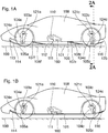
Figs. 1A-B are elevation views of the basic embodiment of the present invention withmovable underbody 101 deployed (1A) and retracted (1B). -
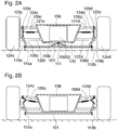
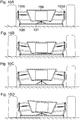
Figs. 2A-B are cross-sectional views of the basic embodiment of the present invention withmovable underbody 101 deployed (2A) and retracted (2B). These views are in accordance withline 2A - 2A ofFig. 1A . -
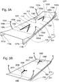
Fig. 3A is a perspective rear three-quarter view of a movable underbody of the basic embodiment of the present invention apart from the rest of the vehicle. -
Fig. 3B is a perspective rear three-quarter view of a movable underbody of an additional embodiment of the present invention apart from the rest of the vehicle. -
Figs. 4A-B are perspective front three-quarter views from below of a vehicle fitted with the basic embodiment of the present invention (4A) and withmovable underbody 101 removed (4B). -
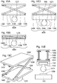
Figs. 5A-D are underside views of thebasic embodiment additional embodiment -
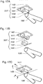
Figs. 6A-C are cross-sectional (6A), exploded (6B), and perspective front three-quarter (6C) views of the basic embodiment of a ball joint 107f that attaches to thefront stabilization linkage 108f. -
Figs. 6D-F are cross-sectional (6D), exploded (6E), and perspective front three-quarter (6F) views of the basic embodiment of a ball joint 107r and slidingmechanism 106 that attach to therear stabilization linkage 108r. -
Figs. 7A-I are views of thebasic embodiment 104c (7A) and additional embodiments (7B-I), including 204c, 304c, 404c, 504c, 604c of support linkages. -
Fig. 8A is a perspective left side view andFig. 8B is an exploded view of the left rearupper control arm 121c with a basicupper support bracket 103c showing means of attachment to a rollerchain support linkage 104c. -
Fig. 8C is a perspective left side view andFig. 8D an exploded view of the left rearupper control arm 121c with a bellcrankupper support bracket 603c and height-adjustment actuator 167c. -
Fig. 8E is a perspective left side view of the left rearupper control arm 121c with an upper support bracket withbellcrank 603c,strain gauge 171c, and height-adjustment actuator 167c. -
Fig. 8F is an exploded perspective left side view of a portion of the left rearupper control arm 121c with a basicupper support bracket 103c and attachment system to acable support linkage 204c. -
Fig. 8G is a perspective left side view of a portion of the left rearupper control arm 121c with a basicupper support bracket 103c attached to a Kevlarwebbing support linkage 304c. -
Figs. 9A-B are perspective right side exploded views of an attachment means for the inlet 114 (9B), movable underbody diffuser 116 (9A), andlower support brackets -
Figs. 9C-H are elevation views of threedifferent diffuser embodiments different inlet embodiments -
Figs. 10A-D are cross-sectional views of a vehicle fitted with the basic embodiment of the present invention at different body positions, in accordance withcross-sectional line 2A - 2A ofFig. 1A . -
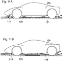
Figs. 11A-B are elevation views of two vehicles fitted either with the basic embodiment of the present invention (11A) or an embodiment with a minimal inlet 214 (11B) showing the path of airflow under thevehicle body 158. -
Figs. 12A-I are elevation views of the front of three vehicles fitted without a movable underbody (12A-C), with a rigidly supported movable underbody 101 (12D-F), and fitted with amovable underbody 101 supported by tensile support linkages, exemplified by 104b (12G-I). -
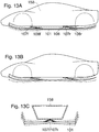
Figs. 13A-C are elevation views (13A-B) and a cross-section view (13C) of a vehicle fitted with the basic embodiment of the present invention showing relative movement of themovable underbody 101. The view ofFig. 13C is in accordance withcross-sectional line 2A - 2A ofFig. 1A . -
Fig. 14A is an elevation view of a fronttelescoping stabilization linkage 308f andmovable underbody 101. -
Figs. 14B-E are transverse cross-sectional (14B) and elevation views (14C-E) of a reartelescoping stabilization linkage 308r, slidingmechanism 106, andmovable underbody 101. -
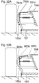
Figs. 15A-C are elevation views (15A-B) and a perspective view (15C) of a frontpantographic stabilization linkage 408f. -
Figs. 15D-E are elevation (15D) and front (15E) views of a rearpantographic stabilization linkage 408r with slidingmechanism 106. -
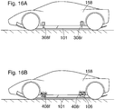
Figs. 16A-B are elevation views of vehicles fitted with either front and reartelescoping stabilization linkages 308f - 308r (16A) or front and rearpantographic stabilization linkages 408f - 408r (16B). -
Figs. 17A-C are perspective front three-quarter views from below (17A and C) and an exploded view (17B) of a front universal joint 207f attached to afront stabilization linkage 108f. -
Figs. 18A-B are perspective front three-quarter views from below of a rear universal joint withintegral slider 207r attached to arear stabilization linkage 108r. -
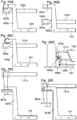
Fig. 19A is a rear view of a basic left rearlower support bracket 105c. -
Figs. 19B-D are a cross-sectional (19B), perspective (19C), and exploded (19D) views of a left rear adjustablelower support bracket 205c. -
Fig. 19E is an elevation view of a left rear adjustable lower support bracket with retractionlinkage attachment point 305c. -
Figs. 20A-B are rear views of a left rearlower control arm 122c with freeupper support bracket 203c and freelower support bracket 405c in engaged, deployed position (20A) and separated, retracted position (20B). -
Fig. 20C is a rear view of a left rearlower control arm 122c with free upper support bracket forroller 303c and free lower support bracket withroller 505c in engaged, deployed position. -
Fig. 20D is a cross-sectional view of the left rear suspension showing an upright-mounted free upper support bracket forroller 503c and a free lower support bracket withroller 505c in engaged, deployed position. -
Figs. 20E-F are rear views of a left rearupper control arm 121c with freeupper support bracket 403c and freelower support bracket 605c in engaged, deployed position (20E) and separated, retracted position (20F). -
Fig. 21A is a perspective left side view of a left rearlower control arm 122c with freeupper support bracket 203c and freelower support bracket 405c in separated, retracted position. -
Fig. 21B is a cross-sectional rear view of the left rear suspension withsupport linkage 104c directly attached to themovable underbody 101. The view inFig. 21B is in accordance withline 2A - 2A inFig. 1A . -
Fig. 21C is a perspective left side view of a left rearlower control arm 122c with free upper support bracket forroller 303c and free lower support bracket withroller 505c in separated, retracted position. -
Fig. 21D is an exploded view of a left rear free lower support bracket withroller 505c (shown inFig. 21C ). -
Fig. 21E is a perspective left side view of a left rearupper control arm 121c with freeupper support bracket 403c and freelower support bracket 605c in separated, retracted position. -
Figs. 22A-B are cross-sectional rear views of the left rear suspension of two vehicles with left rear upper support bracket with sprocket 703c (22A) and left rear upper support bracket withpulley 803c (22B). The direction of sight in these two Figures is in accordance with the direction of sight indicated bycross-sectional line 2A - 2A ofFig. 1A . -
Figs. 23A-C are elevation views of a vehicle with amovable underbody 101 with downforce distributions to the wheels at neutral (23A), forward pitch (23B), and rear pitch (23C) orientations. -
Figs. 24A-B are block diagrams of a movable underbody height-adjustment control means (24A) and a movable underbody retraction control means (24B). -
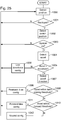
Fig. 25 is a flowchart for a movable underbody height-adjustment electronic control unit ("ECU") 173. -
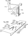
Fig. 26A is a perspective left side view of a left rearupper control arm 121c with an upper support bracket withbasal bellcrank 903c andpushrod 179c. -
Fig. 26B is a perspective rear three-quarter view of a movable underbody device of a third alternative embodiment in accordance with the present invention. -
Figs. 27A-D are cross-sectional views of a vehicle fitted with an upper support bracket withbasal bellcrank 903c andpushrod 179c at different body positions. The direction of sight in these two Figures is in accordance with the direction of sight indicated bycross-sectional line 2A - 2A ofFig. 1A . -
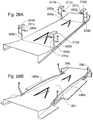
Fig. 28A is a perspective rear three-quarter view of amovable underbody 101 with adjustable lower support brackets with retractionlinkage attachment points 305a - 305d and associatedretraction linkages 211a - 211d andretraction actuators 210a - 210d. -
Fig. 28B is a perspective rear three-quarter view of amovable underbody 501 with side, front, and rear extensions, as well as support braces 188a - 188b, and rigidaerodynamic fences 290. -
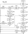
Fig. 29 is a flowchart for a movableunderbody retraction ECU 184. -
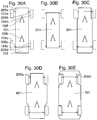
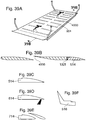
Figs. 30A-E are plan views of several movable underbody embodiments. -
Figs. 31A-B are perspective rear three-quarter views of amovable underbody 801 with adjustable inlet and adjustable diffuser (31A) and a movable underbody with tunnels 601 (31B). -
Figs. 32A-C are perspective rear three-quarter views (32A-B) and exploded view (32C) of an articulating two-elementmovable underbody 701. -
Fig. 33A is a cross-sectional view of a left slidingskirt 119a in deployed position. -
Fig. 33B is a perspective rear three-quarter view of a portion of amovable underbody 101 withleft siding skirt 119a in deployed position. -
Fig. 33C is a cross-sectional view of a left hingedskirt 219a in deployed position and in accordance withline 33C - 33C ofFig. 33F . -
Fig. 33D is a cross-sectional view of a left hingedskirt 219a in deployed position and in accordance withline 33D - 33D ofFig. 33F . -
Fig. 33E is a cross-sectional view of a left hingedskirt 219a in retracted position against the lower surface of avehicle body 158. The view is in accordance withline 33D - 33D inFig. 33F . -
Fig. 33F is a perspective rear three-quarter view of a portion of amovable underbody 101 with left hingedskirt 219a in deployed position. -
Figs. 34A-B are cross-sectional views of the lower surface of avehicle body 158 with foldingaerodynamic fences 190 and amovable underbody 101 in a deployed position (34A) and in a retracted position (34B). The views in these Figures are in accordance withline 34A - 34A ofFig. 23A -
Figs. 34C-L are plan views of amovable underbody 501 with side, front, and rear extensions, and with various arrangements of folding aerodynamic fences 190 (34C, EH) and with the same arrangements of foldingaerodynamic fences 190 showing airflow patterns (34D, I-L). -
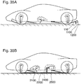
Fig. 35A is an elevation view of a vehicle fitted with the first alternative embodiment in accordance with the present invention. -
Fig. 35B is an elevation view of a vehicle fitted with the second alternative embodiment in accordance with the present invention. -
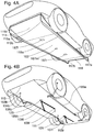
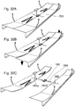
Fig. 36A is a rear three-quarter view of a movable underbody device of the first alternative embodiment in accordance with the present invention. -
Fig. 36B is a rear three-quarter view of a vacuum plate device of the second alternative embodiment in accordance with the present invention. The lower end of thevacuum hose 2400 is partially removed to show thevacuum plate orifice 2300. -
Fig. 37 is a block diagram of a body-mounted movable underbody height-adjustment and retraction control means. -
Fig. 38 is a flowchart for a body-mounted movable underbody height-adjustment ECU 3200. -
Fig. 39A is a perspective rear three-quarter view of a slottedmovable underbody 901. -
Fig. 39B is a longitudinal section of a portion of a slottedmovable underbody 901 showing the shape of aslot 4000 and intervening spaces. -
Fig. 39C-E are elevation views of additional inlet embodiments. -
Fig. 39F is an elevation view of amovable underbody spoiler 516. -
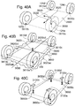
Fig. 40A is a perspective front three-quarter view of a vehicle'swheels 124a - 124d at full suspension compression. -
Fig. 40B is a perspective front three-quarter view of a vehicle'swheels 124a - 124d at example positions as they rest upon aroadway 199. -
Fig. 40C is a perspective front three-quarter view of a vehicle'swheels 124a - 124d at the example positions shown inFig. 40B , along with body-mounted height-adjustment actuators 3100a - 3100d. -
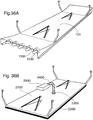
Fig. 41A is a perspective rear three-quarter view of a wingedmovable underbody 10001. -
Fig. 41B is a perspective rear three-quarter view of a frame-likemovable underbody 20001. -
Fig. 41C is a perspective rear three-quarter view of amovable underbody 501 with side, front, and rear extensions, and a pair of complete front wheel fairings, 9000a - 9000b. -
- 101 movable underbody
- 102 movable underbody plate
- 103a - 103d upper support brackets
- 104a - 104d roller chain support linkages
- 105a - 105d lower support brackets
- 106 sliding mechanism
- 107f front ball joint
- 107r rear ball joint
- 108f front stabilization linkage
- 108r rear stabilization linkage
- 109f front stabilization hinge
- 109r rear stabilization hinge
- 110 retraction actuator
- 111 retraction linkage
- 112 retraction linkage fitting
- 113 inlet depression
- 114 inlet
- 115a left inlet fence
- 115b right inlet fence
- 116 movable underbody diffuser
- 117a left movable underbody diffuser fence
- 117b right movable underbody diffuser fence
- 118a left skirt groove
- 118b right skirt groove
- 119a left sliding skirt
- 119b right sliding skirt
- 120 cushioning pad
- 121a - 121d upper control arms
- 122c - 122d lower control arms
- 123c - 123d suspension uprights
- 124a - 124d vehicle wheels
- 125 vehicle body diffuser
- 126f recess of the front stabilization linkage
- 126r recess of the rear stabilization linkage
- 127f ball of front ball joint
- 127r ball of rear ball joint
- 128f socket of front ball joint
- 128r socket of rear ball joint
- 129 mounting plate of front ball joint
- 130 sliding ball base of sliding mechanism
- 131 mounting track of sliding mechanism
- 132f inlet mounting bracket
- 132r diffuser mounting bracket
- 133 bushing of the lower support bracket
- 134f cylinder of front telescoping stabilization linkage
- 134r cylinder of rear telescoping stabilization linkage
- 135f piston of front telescoping stabilization linkage
- 135r piston of rear telescoping stabilization linkage
- 136f base plate of front pantographic stabilization linkage
- 136r base plate of rear pantographic stabilization linkage
- 137f ball plate of front pantographic stabilization linkage
- 137r ball plate of rear pantographic stabilization linkage
- 138f folding support rods of front pantographic stabilization linkage
- 138r folding support rods of rear pantographic stabilization linkage
- 139f support rod hinge of front pantographic stabilization linkage
- 139r support rod hinge of rear pantographic stabilization linkage
- 140f support rod slider of front pantographic stabilization linkage
- 140r support rod slider of rear pantographic stabilization linkage
- 141f base of front universal joint
- 141r base of rear universal joint
- 142f first bracket of front universal joint
- 142r first bracket of rear universal joint
- 143f second bracket of front universal joint
- 143r second bracket of rear universal joint
- 144f support rod of front universal joint
- 144r support rod of rear universal joint
- 145f spider of front universal joint
- 145r spider of rear universal joint
- 146f hinge of front universal joint
- 146r hinge of rear universal joint
- 147c upper arm of left rear articulating support linkage
- 148c lower arm of left rear articulating support linkage
- 149c stop of lower arm of left rear articulating support linkage
- 150c cylinder of left rear telescoping support linkage
- 151c piston of left rear telescoping support linkage
- 152 rod end bearing of support linkage
- 153c inner bracket piece of left rear adjustable lower support bracket
- 154c outer bracket piece of left rear adjustable lower support bracket
- 155c spring of left rear adjustable lower support bracket
- 156c adjustment bolt of left rear adjustable lower support bracket
- 157c washer of left rear adjustable lower support bracket
- 158 vehicle body
- 159c - 159d left rear and right rear support linkage tensioner springs
- 160 retraction linkage tensioner spring
- 161c load bearing surface of the left rear free lower support bracket
- 162c load bearing surface of the left rear free upper support bracket
- 163c wheel fork of left rear lower support bracket with roller
- 164c bearing axle of left rear lower support bracket with roller
- 165c bearing wheel of left rear lower support bracket with roller
- 166c left rear upper support bracket pushrod
- 167c left rear movable underbody height-adjustment actuator
- 168c mounting bracket of left rear upper support bracket with bellcrank
- 169c crank of left rear upper support bracket with bellcrank
- 170c crank mounting pivot bolt of left rear upper support bracket with bellcrank
- 171c left rear downforce-measuring strain gauge
- 172 two-axis accelerometer sensor
- 173 movable underbody height-adjustment ECU
- 174 movable underbody height-adjustment on/off switch
- 175 movable underbody position sensor
- 176a - 176d suspension position sensors
- 177c crank of left rear basal upper support bracket with bellcrank
- 178c mounting bracket of left rear basal upper support bracket with bellcrank
- 179c - 179d pushrods of left rear and right rear basal upper support brackets with bellcrank
- 180c - 180d pushrod mounts of left rear and right rear basal upper support brackets with bellcrank
- 181a left articular cylinder
- 181b right articular cylinder
- 182 peg
- 183 hinged skirt lever
- 184 movable underbody retraction ECU
- 185 electronic stability control system
- 186 retraction switch
- 187f front access panel
- 187m middle access panel
- 187r rear access panel
- 188a left support brace
- 188b right support brace
- 189a left support brace groove
- 189b right support brace groove
- 190 folding aerodynamic fence
- 191f front hinge of movable underbody
- 191r rear hinge of movable underbody
- 192f pushrod of adjustable inlet
- 192r pushrod of adjustable diffuser
- 193f control horn of adjustable inlet
- 193r control horn of adjustable diffuser
- 194 articular rod
- 195 retention band
- 196a left skirt hinge
- 197f adjustable inlet actuator
- 197r adjustable diffuser actuator
- 198f front pylon
- 198r rear pylon
- 199 roadway
- 201 movable underbody with minimal inlet and diffuser
- 203c left rear free upper support bracket for lower control arm
- 204c left rear cable support linkage
- 205a - 205d adjustable lower support brackets
- 207f front universal joint
- 207r rear universal joint with integral slider
- 208f front T-shaped stabilization linkage
- 208r rear T-shaped stabilization linkage
- 210a - 210d corner retraction actuators
- 211a - 211d corner retraction linkages
- 214 upturned minimal inlet
- 216 minimal movable underbody diffuser
- 219a left hinged skirt
- 219b right hinged skirt
- 253c inner bracket piece of left rear lower support bracket with retraction linkage
- 254c outer bracket piece of left rear lower support bracket with retraction linkage
- 260a - 260d corner retraction linkage tensioner springs
- 290 Rigid aerodynamic fence
- 301 movable underbody with front side cutouts
- 303c left rear free upper support bracket for roller
- 304c left rear Kevlar webbing support linkage
- 305a - 305d adjustable lower support brackets with retraction linkage point
- 308f front telescoping stabilization linkage
- 308r rear telescoping stabilization linkage
- 314 symmetrical minimal inlet
- 316 two-element movable underbody diffuser
- 401 movable underbody with side extensions
- 403c left rear free upper support bracket for upper control arm
- 404c left rear articulating support linkage
- 405c left rear free lower support bracket
- 408f front pantographic stabilization linkage
- 408r rear pantographic stabilization linkage
- 414 adjustable inlet
- 416 adjustable diffuser
- 501 movable underbody with side, front, and rear extensions
- 503c left rear upright-mounted free upper support bracket
- 504c left rear telescoping support linkage
- 505c left rear free lower support bracket with roller
- 514 downturned minimal inlet
- 516 movable underbody spoiler
- 601 movable underbody with tunnels
- 603c left rear upper support bracket with bellcrank
- 604c left rear rigid support linkage
- 605c left rear free lower support bracket for upper control arm
- 614 downturned minimal inlet with brush
- 701 two-element movable underbody
- 703c left rear upper support bracket with sprocket
- 704c left rear elongated roller chain support linkage
- 705a - 705d support linkage fittings
- 714 two-element inlet
- 801 adjustable movable underbody
- 803c left rear upper support bracket with pulley
- 804c left rear elongated cable support linkage
- 805c - 805d medially situated lower support brackets
- 901 slotted movable underbody
- 903c - 903d left rear and right rear upper support brackets with basal bellcrank
- 1100 electric fan
- 1200 mounting pylon for electric fan
- 2100 vacuum plate
- 2200 vacuum skirt
- 2300 vacuum plate orifice
- 2400 vacuum hose
- 2500 vacuum generator
- 3100a - 3100d body-mounted height-adjustment actuators
- 3200 body-mounted movable underbody height-adjustment ECU
- 3300a - 3300d laser sensors
- 3400 driver-operated retraction switch
- 3500 reference plane
- 3510a - 3510d wheel support points at full suspension compression
- 3520 reference plane origin
- 3530 X-axis of reference plane
- 3540 Y-axis of reference plane
- 3550 Z-axis orthogonal to reference plane
- 3600 estimated support plane
- 3610a - 3610d wheel support points relative to reference plane
- 3620 Z-intercept of longitudinal and transverse lines of estimated support plane
- 3630 longitudinal line of estimated support plane that intercepts Z-axis
- 3640 transverse line of estimated support plane that intercepts Z-axis
- 3650a - 3650d estimated actuator ride heights
- 4000 movable underbody slot
- 5000 pivot bolt
- 5010 large pivot bolt for Kevlar webbing support linkage
- 6000 master link
- 7000 side plate
- 8000 retaining clip
- 9000a left front complete wheel fairing
- 9000b right front complete wheel fairing
- 10001 winged movable underbody
- 10010f front movable underbody wing
- 10010r rear movable underbody wing
- 10015a left winglet of rear movable underbody wing
- 10015b right winglet of rear movable underbody wing
- 10020a left connecting rod
- 10020b right connecting rod
- 20001 frame-like movable underbody
- 20002 motor
- The basic embodiment of the present invention includes a movable underbody 101 (
Fig. 1A ) below a body 158 (Fig. 1A ) of a vehicle with fourwheels 124a - 124d (Fig. 30A ) and a motor 20002 (Fig. 2A ) adapted to propel the vehicle.Fig. 1A is an elevation view of the left side of the basic embodiment of a vehicle with amovable underbody 101 in its deployed position, in accordance with the present invention.Fig. 1B shows the vehicle with themovable underbody 101 in its retracted position. As shown inFig. 1A , themovable underbody 101 is connected to thevehicle body 158 through a pair of stabilization linkages, front 108f and rear 108r. Themovable underbody 101 is suspended below thevehicle body 158 by foursupport linkages 104a - 104d, each associated with acorresponding vehicle wheel 124a - 124d and attached near or on a corresponding one of the four corner areas of themovable underbody 101. Thesupport linkages 104a - 104d (seeFig. 3A ) are comprised of a leftfront support linkage 104a associated with theleft front wheel 124a, a rightfront support linkage 104b associated with the rightfront wheel 124b (seeFig. 12G ), a leftrear support linkage 104c associated with the leftrear wheel 124c, and a rightrear support linkage 104d associated with the rightrear wheel 124d (seeFig. 2A ). For purposes of this disclosure, the four corner areas of the vehicle and four corner areas of themovable underbody 101, refer to portions of these components located near the fourwheels 124a - 124d of the vehicle. In this disclosure, components that are located in the four corner areas of embodiments of the present invention are designated with the following suffixes: "a" for one in the left front corner area, "b" for one in the right front corner area, "c" for one in the left rear corner area, and the suffix "d" for one in the right rear corner area. Throughout much of this disclosure, only the left rear suspension of the vehicle, left rear corner area of thevehicle body 158, and left rear corner area of themovable underbody 101 and associated structures of the present invention are shown. The other corner areas of the present invention not shown have the same form as the left rear corner area shown, except that the components are reversed on the right side of the vehicle from that shown for the left rear corner area of the vehicle. - Each of the four
support linkages 104a - 104d (seeFig. 3A ) is attached via a correspondingupper support bracket 103a - 103d (seeFig. 3A ), designated left front 103a,right front 103b, left rear 103c, and right rear 103d, to the corresponding end of one of the vehicle's fourupper control arms 121a - 121d (seeFigs. 1A ,2A , and12G ), designated left front 121a,right front 121b, left rear 121c, and right rear 121d. Eachsupport linkage 104a - 104d (seeFig. 3A ) extends downward from the correspondingupper support bracket 103a - 103d (seeFig. 3A ) to alower support bracket 105a - 105d (seeFig. 3A ), designated left front 105a,right front 105b, left rear 105c, and right rear 105d, attached to the corresponding corner area of themovable underbody 101. Although thelower support brackets 105a - 105d (or their variations) are herein described separately from themovable underbody 101, they are each effectively a part of the corresponding corner area of the movable underbody 101 (or its variations). A vehicle with double wishbone suspension is shown throughout this disclosure, but it is in accordance with the present invention to mount the device of the present invention to vehicles fitted with other types of suspension system, including McPherson/Chapman strut suspensions (see below under additional embodiments of the upper support brackets). - Both the
front stabilization linkage 108f andrear stabilization linkage 108r are articulated with thevehicle body 158 through a ball joint, labeled 107f for the front ball joint and 107r for the rear ball joint. The ball joint 107r connected to therear stabilization linkage 108r is attached through a longitudinally oriented sliding mechanism 106 (or "slider") to the undersurface of thevehicle body 158. At the opposite end of both thefront stabilization linkage 108f andrear stabilization linkage 108r is a divided, transversely oriented hinge, labeled 109f (seeFig. 3A ) for the front hinge and 109r (seeFig. 3A ) for the rear hinge. Thefront hinge 109f andrear hinge 109r are each articulated to the upper side of themovable underbody 101. - Near its midpoint the
movable underbody 101 is connected via a fitting 112 to aretraction linkage 111 that extends to aretraction actuator 110 within thevehicle body 158. Aretraction tensioner spring 160 extends from theretraction linkage 111 to thevehicle body 158. Theretraction actuator 110 may be one of several different types, including, for example, an electric, pneumatic, or hydraulic actuator. Theretraction linkage 111,retraction actuator 110, andretraction tensioner spring 160 are components of an exemplary "retraction means." Other embodiments of the retraction means are disclosed herein and may be used instead. - The front portion of the
movable underbody 101 is curved upward to form anunderbody inlet 114 that is accommodated by aninlet depression 113 on thevehicle body 158. The rear portion of themovable underbody 101 is gradually bent upward to form a movable underbody diffuser 116 (seeFig. 1B ) that is accommodated by a correspondingvehicle body diffuser 125 at the rear of thevehicle body 158. Other embodiments of amovable underbody inlet 114 andmovable underbody diffuser 116 are disclosed herein and may be used instead. Between theinlet 114 andunderbody diffuser 116 is the movable underbody plate 102 (seeFig. 3A ). Theinlet 114,movable underbody plate 102, and movable underbody diffuser 116 (Fig. 1B ) comprise themovable underbody 101. While themovable underbody 101 is herein described as comprising three parts (viz.inlet 114,movable underbody plate 102, and movable underbody diffuser 116), themovable underbody 101 may be considered and constructed as one indivisible structure or as a structure with alternative subdivisions. For example, theinlet 114 and/ormovable underbody diffuser 116 may be completely continuous with the rest of themovable underbody 101. Because thelower support brackets 105a - 105d (Fig. 3A ) are rigidly fixed to themovable underbody 101, they may also be constructed as integral, inseparable parts of themovable underbody 101. - For purposes of this disclosure, the
vehicle body 158 includes all of the fully-sprung components of the vehicle that are isolated from the movements of thewheels 124a - 124d and end of the suspension by the shock-damping system of the vehicle's suspension system. For purposes of this disclosure, "suspension system" refers to those components of the vehicle that connect each of thewheels 124a - 124d to the fully-sprungbody 158 and that permit relative vertical displacement of thewheel 124a - 124d and thevehicle body 158. The unsprung components of the vehicle's suspension are those components of the suspension that substantially reciprocate with one or more of thewheels 124a - 124d of the vehicle. -
Fig. 2A is a cross-sectional rear view immediately behind therear wheels 124c - 124d of the basic embodiment of a vehicle in accordance with the present invention and in accordance withline 2A - 2A ofFig. 1A . Therear wheels 124c - 124d and the suspension of the vehicle are shown inFig. 2A , along with themovable underbody 101 in its deployed position.Fig. 2B shows the same, with themovable underbody 101 in its retracted position. In addition to the elements illustrated inFig. 1A and listed in the preceding paragraphs,Figs. 2A and 2B show the rear support linkage tensioner springs 159c and 159d. Also shown are several components of the vehicle's suspension system, includinglower control arms upper control arms suspension uprights vehicle body 158 is not shown and therear wheels 124c - 124d are shown only in outline rather than cross-section. The same convention is maintained in all cross-sectional rear views taken from immediately behind therear wheels 124c - 124d in accordance withline 2A - 2A ofFig. 1A . - The sides of the
movable underbody 101 bear abrasion-resistant aerodynamic skirts, designated 119a for the left sliding skirt and 119b for the right sliding skirt. Theaerodynamic skirts 119a - 119b are slidingly recessed into corresponding skirt grooves, left 118a and right 118b, at the sides of themovable underbody 101.Fig. 33B is a perspective rear three-quarter view from above of the left side portion of amovable underbody 101 with a left slidingskirt 119a in deployed position.Fig. 33A is a cross-sectional view of a left slidingskirt 119a in deployed position in accordance withline 33A - 33A ofFig. 33B . The slidingskirts 119a - 119b may be constructed from a low friction, abrasion-resistant material, such as, for example, glass-reinforced plastic ("GRP") strips. Alternatively, the slidingskirts 119a - 119b may be deleted altogether from the design. - Another embodiment of an aerodynamic skirt is disclosed herein and may be used instead. For purposes of clarity, the aerodynamic skirts are not shown in
Figs. 1A and 1B and in the other side views of the vehicle. Additionally,aerodynamic fences 190, as described under additional embodiments of the movable underbody and appearing, for example, inFigs. 34A through 34L , are not shown in any side views of the vehicle. -
Fig. 3A is a perspective rear three-quarter view of the basic embodiment of amovable underbody 101 in accordance with the present invention, without the body, wheels, and suspension components of the vehicle shown. In addition to the elements illustrated inFig. 1A and listed above,Fig. 3A shows recesses, front 126f and rear 126r, for thestabilization linkages movable underbody 101 and the divided hinges, front 109f and rear 109r, connecting thestabilization linkages movable underbody 101. In this basic embodiment, themovable underbody 101 is of substantially planar form with a raisedinlet 114 and a raiseddiffuser 116, with theinlet 114 bounded on each side by a vertically-oriented lateral inlet fence, left 115a (shown inFig. 4A ) and right 115b, and themovable underbody diffuser 116 bounded on each side by a vertically-oriented lateral diffuser fence, left 117a and right 117b. Other embodiments of themovable underbody inlet 114 andmovable underbody diffuser 116 are disclosed herein and may be used instead. For purposes of clarity, thelateral inlet fences 115a - 115b andlateral diffuser fences 117a - 117b are not shown inFigs. 1A and 1B and in other side views of the vehicle. Thelateral inlet fences 115a - 115b andlateral diffuser fences 117a - 117b may also be omitted from the design of a movable underbody. -
Fig. 30A is a plan view of the basic embodiment of amovable underbody 101 in accordance with the present invention, showing the relative position between themovable underbody 101 and the fourwheels 124a - 124d of the vehicle.Fig. 4A is a perspective front three-quarter view from below of the basic embodiment of amovable underbody 101 in accordance with the present invention.Fig. 4A shows themovable underbody 101 in its deployed position. This figure also shows the relative position between themovable underbody 101 and fourwheels 124a - 124d (seeFig. 30A ) of the vehicle.Fig. 4B is the same view asFig. 4A , but with themovable underbody 101 removed to show the mounting hardware connecting themovable underbody 101 to the vehicle. In this basic embodiment, themovable underbody 101 is rectangular and occupies most of the area between the fourwheels 124a - 124d (seeFig. 30A ) of the vehicle. Themovable underbody 101 may be constructed from a material that is both light and very stiff, such as honeycomb aluminum or a stressed-skin panel of carbon fiber laminate. Other materials may also be suitable. Other embodiments of themovable underbody 101 are disclosed herein and may be used instead. -
Figs. 5A and 5B are underside views of the basic embodiment of the front andrear stabilization linkages stabilization linkages Fig. 5A shows thefront stabilization linkage 108f, which is attached at its front end to a ball joint 107f that articulates directly to the undersurface of the vehicle body 158 (seeFig. 1A ). The base of thefront stabilization linkage 108f is attached to a dividedhinge 109f that articulates through a transverse axis with the movable underbody 101 (seeFig. 1A ).Fig. 5B shows therear stabilization linkage 108r that is attached at its front end to a ball joint 107r that is mounted on a slidingmechanism 106 that attaches to the undersurface of the vehicle body 158 (seeFig. 1A ). The base of therear stabilization linkage 108r is attached to a dividedhinge 109r that articulates through a transverse axis with the movable underbody 101 (seeFig. 1A ). Thestabilization linkages Figs. 5C and 5D , are discussed hereinbelow and may be used instead. -
Fig. 6A is a cross-sectional view in accordance withline 6A - 6A ofFig. 6C of a front ball joint 107f in accordance with the present invention.Fig. 6B is an exploded view of the front ball joint 107f in accordance with the present invention. The front ball joint 107f is connected to thefront stabilization linkage 108f. The front ball joint 107f includes aball 127f andsocket 128f, and is attached to a mountingplate 129 that attaches to the undersurface of the vehicle body 158 (Fig. 1A ).Fig. 6C is a perspective three-quarter front view of the front ball joint 107f and a portion of thefront stabilization linkage 108f.Fig. 6D is a cross-sectional view in accordance withline 6D - 6D ofFig. 6F of the slidingmechanism 106 and rear ball joint 107r in accordance with the present invention.Fig. 6E is an exploded view of the slidingmechanism 106 and rear ball joint 107r. The slidingmechanism 106 is comprised of a slidingball base 130 that moves longitudinally within a mountingtrack 131. The rear ball joint is comprised of aball 127r attached to the slidingball base 130, and asocket 128r attached to the front end of therear stabilization linkage 108r.Fig. 6F is a perspective three-quarter front view of the slidingmechanism 106, ball joint 107r, and a portion of therear stabilization linkage 108r. Other embodiments of front and rear ball joints and sliding mechanisms are disclosed herein and may be used instead. -
Fig. 7A is a rear view of the basic embodiment of a leftrear support linkage 104c in accordance with the present invention with associated left rearupper support bracket 103c and left rearlower support bracket 105c. This basic embodiment of thesupport linkage 104c includes a length of roller chain. The other support linkages of this embodiment, 104a, 104b, and 104d (seeFig. 3A ), are identical. Other embodiments of the support linkages are disclosed herein and may be used instead. -
Fig. 8A is a side perspective view of the basic embodiment of a left rearupper support bracket 103c mounted to the rear side of the free end of the left rearupper control arm 121c along with the leftrear support linkage 104c.Fig. 8B is an exploded view of the same showing how thesupport linkage 104c may simply link to theupper support bracket 103c using normal roller chain link hardware consisting of amaster link 6000,side plate 7000, and retainingclip 8000. - The left and right front
upper support brackets Fig. 3A ), may be positioned on the frontupper control arms Fig. 1A ) opposite to the steering arms of the front suspension uprights. Such a mounting point allows thefront support linkages Fig. 3A ) that hang from the frontupper support brackets Fig. 3A ) to not interfere with the movements of the vehicle's steering arms. Other mounting points and embodiments of theupper support brackets 103a - 103d are in accordance with the invention, including those disclosed elsewhere herein, and may be used instead. Theupper support brackets 103a - 103d may be of a sufficiently strong, durable material, such as chromoly steel. Other materials may be used instead. For secure attachment they may be welded to theupper control arms 121a - 121d (Fig. 1A ,2A , and12G ) or completely integrated into the design of theupper control arms 121a - 121d (Fig. 1A ,2A , and12G ). -
Fig. 9A is a side perspective view of the basic embodiment of a right rearlower support bracket 105d in accordance with the present invention and an example of how the bracket may be secured to the movable underbody 101 (Fig. 1A ).Fig. 9A also shows how themovable underbody diffuser 116 may be secured to the rear edge of themovable underbody plate 102 through adiffuser mounting bracket 132r.Fig. 9B is a side perspective view of the basic embodiment of a right frontlower support bracket 105b in accordance with the present invention. This figure illustrates an example of how thebracket 105b may be secured to themovable underbody plate 102 and how theinlet 114 may be attached to the front edge of themovable underbody plate 102 with aninlet mounting bracket 132f. Therubber bushings 133 that may be included with the lower support bracket mountings provide a slight amount of cushioning to the movable underbody 101 (Fig. 1A ) against vehicle suspension vibrations. There are many other ways that such cushioning may be provided including a small spring and damper unit situated between either a) thelower support brackets 105a - 105d (Fig. 3A ) andcorresponding support linkages 104a - 104d (Fig. 3A ) or b) between theupper support brackets 103a - 103d (Fig. 3A ) andcorresponding support linkages 104a - 104d (Fig. 3A ). Alternatively, no cushioning may be provided between the movable underbody 101 (Fig. 1A ) and suspension system. Other embodiments of thelower support brackets 105a - 105d (Fig. 3A ) are disclosed herein and may be used instead. The lower support brackets may be constructed from various materials, including a carbon fiber layup or chromoly steel. - In its deployed position, as shown in side view in
Fig. 1A and rear cross-sectional view inFig. 2A , themovable underbody 101 is supported below thevehicle body 158 by the foursupport linkages 104a - 104d (Fig. 3A ), each of which is connected to a corresponding end of one of the fourupper control arms 121a - 121d (Fig. 1A ,2A ,12G ) in a vehicle with double wishbone suspension. When deployed, thesupport linkages 104a - 104d (Fig. 3A ) are pulled taut by the weight and generated downforce of the movable underbody 101 (Fig. 1A ). Because the end of eachupper control arm 121a - 121d substantially maintains a constant distance above theroadway 199, themovable underbody 101 in its deployed position correspondingly maintains a substantially constant positional relationship with respect to theroadway 199, regardless of the height and orientation of thevehicle body 158 above the roadway 199 (Fig. 10A ). -
Figs. 10A-D are cross-sectional views immediately behind the rear wheels of the basic embodiment of a vehicle in accordance with the present invention, in accordance withline 2A - 2A ofFig. 1A .Figs. 10A-C show thevehicle body 158 at normal, lowered, and elevated positions, respectively. As can be seen, there is a constant positional relationship between themovable underbody 101 androadway 199 in these figures.Fig. 10D shows thevehicle body 158 during body roll. Again, the same positional relationship between themovable underbody 101 androadway 199 exists here as well. The twostabilization linkages 108f (Fig. 1A ) and 108r (Fig. 1A ) serve to stabilize the position of themovable underbody 101 throughout its range of motion so that themovable underbody 101 may not swing back and forth from its points of support on the suspension of the vehicle. -
Fig. 11A is an elevation view of the basic embodiment of a vehicle in accordance with the present invention with amovable underbody 101 in its deployed position. This figure indicates the path of airflow under the vehicle as the vehicle travels. Themovable underbody 101 forms a venturi duct with theroadway 199 when themovable underbody 101 is deployed. As the vehicle travels, the airstream below themovable underbody 101 is accelerated in the narrow venturi throat that is formed by much of the area of themovable underbody 101. This accelerated air exhibits decreased pressure, creating downforce that is applied directly to the ends of the suspension through thesupport linkages 104a - 104d (Fig. 3A ). The production of downforce in this way may be termed aerodynamic ground effect. Because this airflow is at least partially isolated from the undersurface of thevehicle body 158 and may be partially isolated from the space surrounding the vehicle suspension andvehicle wheels 124a - 124d (Fig. 30A ), it may also generate less aerodynamic drag than is generated by the corresponding airflow in a vehicle not equipped with a movable underbody in accordance with the present invention. - The
movable underbody 101 is retracted by activation of the retraction actuator 110 (Fig. 1A ). When activated, theretraction actuator 110 pulls on the retraction linkage 111 (Fig. 1A ) and, through that linkage, lifts themovable underbody 101 to thevehicle body 158. Themovable underbody 101 is shown in its retracted position in side view inFig. 1B and rear cross-sectional view inFig. 2B . In the retracted position, themovable underbody 101 andstabilization linkages vehicle body 158 with thestabilization linkages Fig. 1A ) recessed within their corresponding stabilization linkage recesses 126f and 126r (Fig. 3A ). When in the retracted position, themovable underbody 101 no longer moves with the suspension, but is instead fixed against the undersurface of the vehicle by theretraction linkage 111 andstabilization linkages Fig. 1A ). Cushioning pads 120 (shown inFig. 2A ) mounted to the undersurface of thevehicle body 158 cushion themovable underbody 101 in its retracted position against thevehicle body 158. - The
support linkages 104a - 104d (Fig. 3A ) serve both to control the orientation of themovable underbody 101 and to support and transfer the vertical load from themovable underbody 101 to the suspension of the vehicle when themovable underbody 101 is deployed. By using roller chain for thesupport linkages 104a - 104d, the linkages may transmit substantial force only through tension. When subjected to a compressive force, aroller chain linkage 104a - 104d simply goes slack and becomes unable to transfer substantial force. Any support linkage that is compliant to compression in this way is herein termed a "tensile" support linkage. A tensile support linkage may be adapted to provide some degree of resistance to compression as long as that force of resistance is low enough to allow themovable underbody 101 to be retracted without substantial resistance and to move independently with respect to thevehicle wheels 124a-124d (Fig. 30A ). InFig. 1B , the support linkages, exemplified by 104a and 104c, are shown bent to the rear for illustrative purposes. Similarly, inFig. 12H the support linkage, exemplified by 104b, is shown bent to the front for illustrative purposes. As shown inFig. 2B , in the basic embodiment the support linkages are actually pulled toward the center of the vehicle by the support linkage tensioner springs, exemplified by 159c and 159d. - By using
tensile support linkages 104a - 104d (Fig. 3A ), retraction of themovable underbody 101 by a separate retraction means functionally disengages themovable underbody 101 from the suspension by unloading and compressing the foursupport linkages 104a - 104d. When retracted, themovable underbody 101 does not pull down on the suspension and does not influence suspension movements. In contrast, if retraction of themovable underbody 101 were to be achieved by elevation through thesupport linkages 104a - 104d, there would be no functional disengagement of themovable underbody 101 from the vehicle's suspension (see additional embodiments of the retraction means). The ability to both retract and functionally disengage the movable underbody from the vehicle's suspension is a very significant advantage of the present invention over the prior art. - The ability to retract the
movable underbody 101 allows ground clearance to be raised when the characteristics of theroadway 199 do not allow for the passage of a low-ground-clearance vehicle. Additionally, themovable underbody 101 may remain retracted when high levels of downforce are not required, as in most everyday driving. For example, deployment of themovable underbody 101 may be reserved for when the vehicle is to be driven at higher speeds on a closed-course racetrack. For regular road travel, themovable underbody 101 may be deployed only when high levels of downforce are needed for purposes of safety, as during emergency braking or for when a loss of vehicle traction is detected, as may occur when theroadway 199 becomes slippery with rain, snow, ice, oil, or other substances that may decrease vehicle traction. - Deployment of the
movable underbody 101 is accomplished by reversing the retraction actuator 110 (Fig. 1A ), thereby undoing the tension in the retraction linkage 111 (Fig. 1A ). When themovable underbody 101 is deployed, slack in the retraction linkage 111 (Fig. 1A ) is taken up by the retraction linkage tensioner spring 160 (Fig. 1A ). Upon deployment, themovable underbody 101 comes to rest upon thesupport linkages 104a - 104d (Fig. 3A ), functionally reengaging themovable underbody 101 with the suspension. The force of gravity and aerodynamic forces may deploy themovable underbody 101 into its deployed position. An actuator system may also be included to push themovable underbody 101 into its deployed position and to potentially transfer load from thevehicle body 158 to themovable underbody 101. - Using
tensile support linkages 104a - 104d, the mass of themovable underbody 101 and associated structures is not fixed to the unsprung mass of the vehicle. This benefits vehicle handling because it allows the suspension to more rapidly adjust to irregularities in theroadway 199. The use oftensile support linkages 104a - 104d also has the benefit in that it makes themovable underbody 101 compliant upon impact with theroadway 199 or objects thereon. -
Figs. 12A-I are elevation views of the right side of the front of three different vehicles as they travel over a depression in the roadway 199 (Fig. 10A ). Typically, such depressions are merely slight negative undulations in the roadway 199 (Fig. 10A ).Figs. 12A-C show a vehicle that is not fitted with a movable underbody.Figs. 12D-F show a vehicle that is fitted with amovable underbody 101 supported by anincompressible support linkage 604b (seeFig. 7I and additional embodiments of the support linkages below).Figs. 12G-I show a vehicle that is fitted with the basic embodiment of the present invention that includes amovable underbody 101 supported by atensile support linkage 104b. - As shown in
Fig. 12H , when awheel 124b (Fig. 12G ) of a vehicle fitted with amovable underbody 101 supported by tensile support linkages, as exemplified by 104b (Fig. 12G ), travels over a depression in theroadway 199, the wheel (frontright wheel 124b shown) may drop to contact the surface of that depression without simultaneously dropping themovable underbody 101. This is because a tensile support linkage, as exemplified by 104b, is only capable of transmitting a downward pull from themovable underbody 101 to the vehicle suspension. That is, such a linkage arrangement cannot apply a compressive force to the vehicle suspension. As a result, the downward movement of thewheel 124b is unhindered by the mass and aerodynamic resistance of themovable underbody 101. This decoupling leads to greater contact between thewheel 124b (Fig. 12G ) and theroadway 199 compared with the movement of awheel 124b (Fig. 12G ) of a vehicle fitted with amovable underbody 101 that is supported by a rigid, incompressible support linkage, exemplified by 604b (Fig. 12D ). As shown inFig. 12E , when such a wheel travels over a depression, the mass and vertical air resistance of themovable underbody 101 resist the downward movement of thewheel 124b (Fig. 12D ), leading to less contact between thewheel 124b and theroadway 199. A physical separation between thewheel 124b androadway 199 is shown inFig. 12E for illustrative purposes. Under normal conditions, thewheel 124b is merely unweighted as the vehicle travels over depressions on theroadway 199. The point is that thewheel 124b of a vehicle equipped with amovable underbody 101 supported byfreelycompressible support linkages 104a - 104d (Fig. 3A ) experiences less unweighting than thewheel 124b of a vehicle equipped with amovable underbody 101 supported by rigid support linkages, exemplified by 604b (Fig. 12D ), traveling over the same depression. - Returning attention to the vehicle fitted with the
tensile support linkage 104b, when the vehicle suspension subsequently compresses after the depression is passed, as shown inFig. 12I , themovable underbody 101, through its connection to the suspension via thetensile support linkage 104b, helps to suppress excessive wheel jounce. This contrasts with a vehicle that is not fitted with amovable underbody 101 supported from the vehicle's suspension, such as shown inFig. 12C . InFig. 12C , thewheel 124b loses contact with the roadway due to excessive wheel jounce. While a physical separation between thewheel 124b and theroadway 199 is shown inFig. 12C , thewheel 124b would normally be merely unweighted as the vehicle travels past a depression in theroadway 199. The point is that thewheel 124b of a vehicle equipped with amovable underbody 101 supported bytensile support linkages 104a - 104d experiences less unweighting than thewheel 124b of a vehicle without a movable underbody. - The resistance to upward movement of the
wheel 124b mentioned above is a consequence of more than simply the downforce generated aerodynamically by themovable underbody 101. It is also a consequence of the inertia of themovable underbody 101 and, importantly, the physical resistance of the system to changes in the separation distance between themovable underbody 101 and the roadway 199 (Fig. 10A ) (i.e. the ride height of the movable underbody). Changes in this separation distance translate to changes in the volume of air between themovable underbody 101 and theroadway 199. When themovable underbody 101 moves away from theroadway 199 there is an increase in that volume of air, which forces air to rush in from the perimeter of themovable underbody 101. In a sense, themovable underbody 101 acts like an expansive diaphragm resisting changes in ride height from theroadway 199. Given the time scale associated with most suspension movements and the low ride height at which themovable underbody 101 may be supported, the airflow from the perimeter of themovable underbody 101 is severely limited, particularly airflow entering from the sides of themovable underbody 101 when sliding 119a - 119b (Fig. 2A ) or hingedaerodynamic skirts 219a - 219b (Figs. 33C and34A ) are employed. In particular, hinged aerodynamic skirts allow air to escape from under themovable underbody 101, but prevent air from entering that space. The result is that the force generated by themovable underbody 101 that resists an upward movement of themovable underbody 101 above its set ride height is greater than the sum of its inertia and the aerodynamic downforce generated by the structure. This means that, while the wheels of the vehicle may move downward without resistance to contact theroadway 199, there is considerable resistance generated against an upward movement away from theroadway 199. The wheels of the vehicle are effectively sandwiched between theroadway 199 below and themovable underbody 101 above. The advantage for a vehicle equipped in accordance with the basic embodiment of the present invention over the other vehicles shown inFigs. 12A-F is increased contact between the tires androadway 199 during vehicle travel. This increase in what is termed "mechanical grip" is in addition to the increased "aerodynamic grip" brought about by the generated downforce of the ground effectmovable underbody 101 and is a further, significant advantage of the present invention over the prior art. Additionally, because upward movement of the wheels above theroadway 199 is counteracted by themovable underbody 101, there is less road bumpiness and vibration transmitted through the vehicle's suspension to thevehicle body 158, resulting in a somewhat smoother ride for the occupants of the vehicle when themovable underbody 101 is deployed. - The front and
rear stabilization linkages Fig. 1A ) serve to limit themovable underbody 101 to a single path of movement. For any given vertical position and orientation about a horizontal axis, the twostabilization linkages movable underbody 101 in terms of its longitudinal and lateral positions, as well as prevent rotation of themovable underbody 101 about a vertical axis (yaw). More specifically, longitudinal movements of themovable underbody 101 are prevented by thefront stabilization linkage 108f because that linkage is connected to thevehicle body 158 at a fixed point, unlike therear stabilization linkage 108r that connects to thevehicle body 158 through a sliding mechanism 106 (Fig. 1A ). Lateral movements of themovable underbody 101 are prevented by the strength of the front andrear stabilization linkages Fig. 3A ). Rotation of themovable underbody 101 about a vertical axis (yaw) is prevented by the physical separation between the twostabilization linkages rear stabilization linkage 108r primarily serves to prevent such rotation of themovable underbody 101 about a vertical axis. -
Figs. 13A and 13B are elevation views of the basic embodiment of a vehicle in accordance with the present invention.Fig. 13C is a cross-sectional view immediately behind the rear wheels of the basic embodiment of a vehicle, in accordance withline 2A - 2A ofFig. 1A . The degrees of freedom of movement of themovable underbody 101 relative to thevehicle body 158 are shown. While thestabilization linkages movable underbody 101, as described above, they allow themovable underbody 101 to move freely in several ways. As shown inFig. 13A , the articulations (ball joints 107f and 107r shown, hinges 109f and 109r (Fig. 3A )) of thestabilization linkages movable underbody 101 to be raised and lowered relative to thevehicle body 158. This allows themovable underbody 101 to conform to changes in vehicle ride height (heave) during travel. This vertical movement is not perfectly linear, but describes a shallow curve with a radius equal to the length of thefront stabilization linkage 108f because that linkage is not attached to a sliding mechanism. The absence of a sliding mechanism in the front is different from the configuration in the rear. Specifically, therear stabilization linkage 108r is attached to slidingmechanism 106. As shown inFig. 13B , the slidingmechanism 106 and articulations (ball joints 107f and 107r shown, hinges 109f and 109r shown inFig. 3A ) of thestabilization linkages movable underbody 101 to rotate about a transverse axis relative to thevehicle body 158. This allows themovable underbody 101 to conform to changes in vehicle pitch during travel. As shown inFig. 13C , the ball joints 107f and 107r connected to thestabilization linkages movable underbody 101 to rotate about a longitudinal axis relative to thevehicle body 158. This allows themovable underbody 101 to conform to changes in vehicle roll during travel. The combination of these separate freedoms of movement (heave, pitch, and roll) allows themovable underbody 101 to follow any change in the positional relationship between thevehicle body 158 androadway 199 during vehicle travel. - Additional embodiments of certain components are described below.
-
Figs. 5C-D are underside views of a first additional embodiment of the front and rear stabilization linkages in accordance with the present invention. These stabilization linkages, front 208f and rear 208r, are T-shaped rather than V-shaped. Both linkages are attached to an apical ball joint, front 107f and rear 107r, and a basal hinge, front 109f and rear 109r, the same as described for the basic embodiment. The ball joint 107r attached to therear stabilization linkage 208r is coupled with a slidingmechanism 106 like that described for the basic embodiment. Both T-shaped 208f and 208r and V-shaped 108f and 108r (Figs. 5A and 5B ) stabilization linkages allow for a comparatively wide hinge articulation with the movable underbody 101 (Fig. 1A ) that helps resist the horizontal loads caused by the acceleration, deceleration, and lateral acceleration of the vehicle. The stabilization linkages may be of other sizes and shapes and of unequal size and shape without departing from the present invention. - The front and
rear stabilization linkages Figs. 5A and 5B ) of the basic embodiment and firstadditional embodiment Fig. 1A ) to attach across the midline of themovable underbody 101. With this arrangement, themovable underbody 101 moves up and away relative to thevehicle body 158 upon forward impact with the roadway 199 (Fig. 10A ) or objects thereon. It is also possible for the stabilization linkages to be mounted such that they extend forward from thevehicle body 158 to themovable underbody 101. - There are other arrangements of stabilization linkages that will achieve a similar result of substantially fixing the horizontal position of the movable underbody 101 (
Fig. 1A ) while allowing themovable underbody 101 to freely move vertically and orient about any horizontal axis. A single linkage may be used, but this arrangement does not well resist rotation of themovable underbody 101 about a vertical axis. More than two linkages may be used if they are aligned or nearly so. The linkages may also be located away from the midline of themovable underbody 101, even upon the base of the suspension, and aligned along other than a longitudinal axis. None of these variants, however, is as simple or effective as those of the embodiments described above. Additionally, the linkages may be reversed in orientation so that the stabilization hinges 109f and 109r are mounted on the vehicle body 158 (Fig. 1A ) and the ball joints 107f and 107r mounted on thevehicle underbody 101.Fig. 3B shows this latter arrangement using T-shapedstabilization linkages - In addition to the various possible shapes and arrangements of simple stabilization linkages just discussed, additional, but somewhat more complex linkage embodiments in accordance with the present invention are illustrated in
Figs. 14 - 16 .Fig. 14A is an elevation view of a fronttelescoping stabilization linkage 308f andmovable underbody 101. The fronttelescoping stabilization linkage 308f is shown in its fully retracted position and attached to themovable underbody 101. The linkage consists of a front cylinder 134f that slidingly accommodates afront piston 135f. Thefront piston 135f is attached to a front ball joint 107f, as described for the preferred stabilization linkage embodiment, comprising afront ball 127f that articulates with afront socket 128f. Thefront socket 128f is attached within themovable underbody 101. -
Fig. 14B shows a transverse cross-sectional view of a vertically oriented reartelescoping stabilization linkage 308r taken alongline 14B - 14B ofFig. 14E . The reartelescoping stabilization linkage 308r is shown in partially extended position. The linkage comprises afront cylinder 134r that slidingly accommodates arear piston 135r. The front andrear pistons 135f (Fig. 14A ) and 135r (Fig. 14B ) include appropriately sized air holes on their upper surfaces (not shown) to allow air to freely move within thetelescoping stabilization linkages 308f (Fig. 14A ) and 308r (Fig. 14B ). Therear piston 135r is attached to a rear ball joint 107r, as described for the preferred stabilization linkage embodiment, comprising arear ball 127r that articulates with arear socket 128r. Therear socket 128r is connected to a slidingmechanism 106 as described for the preferred sliding mechanism embodiment, comprising aball base 130 that slides longitudinally within a mountingtrack 131. The slidingmechanism 106 is attached within themovable underbody 101.Fig. 16A is an elevation view of the left side of a vehicle fitted with amovable underbody 101 andtelescoping stabilization linkages -
Figs. 14C-E are elevation views of the reartelescoping stabilization linkage 308r showing the freedoms of movement of themovable underbody 101.Fig. 14C shows rotation of themovable underbody 101 about a transverse axis.Fig. 14D shows elevation and depression of themovable underbody 101.Fig. 14E shows fore-and-aft motion of themovable underbody 101. Rotation of themovable underbody 101 about a longitudinal axis (not shown) is the same as shown inFig. 14C , but as seen from frontal view. With respect to the fronttelescoping stabilization linkage 308f, the freedoms of movement of themovable underbody 101 are the same, except that there is no fore-and-aft freedom of movement. -
Figs. 15A-E show front and rear stabilization linkages of a pantographic design in accordance with the present invention.Fig. 15A is an elevation view andFig. 15C is a perspective three-quarter view of a frontpantographic stabilization linkage 408f in an extended position. The frontpantographic stabilization linkage 408f comprises afront base plate 136f andfront ball plate 137f connected by two sets of frontfolding support rods 138f. One end of each front folding support rod is articulated through a frontsupport rod hinge 139f to either thefront base plate 136f orfront ball plate 137f while the other end of each front folding support rod is attached to either the base plate or ball plate through a frontsupport rod slider 140f. Thefront ball plate 137f is attached to a front ball joint 107f (Fig. 1A ) as described for the basic embodiment with theball 127f of the front ball joint 107f (Fig. 1A ) shown inFigs. 15A-C and theball 127r of the rear ball joint 107r (Fig. 1A ) shown inFigs. 15D-E. Fig. 15B is an elevation view of a frontpantographic stabilization linkage 408f in its fully elevated position.Fig. 15D is an elevation view andFig. 15E a front view of a rearpantographic stabilization linkage 408r in an extended position. The rearpantographic stabilization linkage 408r includes equivalent components to those described for the frontpantographic stabilization linkage 408f, viz.rear base plate 136r,rear ball plate 137r, rearfolding support rods 138r, rear support rod hinges 139r, and rearsupport rod sliders 140r, interconnected in the same way as described above for the pantographicfront stabilization linkage 408f. Therear ball plate 137r of the rearpantographic stabilization linkage 408r is attached to a slidingmechanism 106 as described with reference to the above-disclosed basic embodiment comprising a mountingtrack 131 and slidingball base 130. The slidingball base 130 is attached to a rear ball joint 107r (Fig. 1A ) as described for the basic embodiment with theball 127r of the rear ball joint 107r (Fig. 1A ) shown inFigs. 15D-E . Alternatively, theball 127r of the rear ball joint 107r (Fig. 1A ) may be directly attached to therear ball plate 137r and the slidingmechanism 106 attached to themovable underbody 101, as described above for the reartelescoping stabilization linkage 308r (Fig. 14B ).Fig. 16B is an elevation view of the left side of a vehicle fitted with amovable underbody 101 and pantographic stabilization linkages, 408f and 408r. - Stabilization linkages of both telescoping and pantographic design allow the
movable underbody 101 to have a linear, vertical path of movement. - The foregoing disclosure of stabilization linkage embodiments and alternative arrangements should be read as illustrative of stabilization linkage means only and should not be construed as limiting. It is possible, though not desirable, to eliminate the stabilization linkage means altogether from a design of a movable underbody device in accordance with the present invention. Without such a stabilization linkage means, however, the
movable underbody 101 will tend to swing from its support linkage attachment points on the vehicle's suspension. It is possible to design an alternative system for stabilizing the horizontal position of themovable underbody 101 that involves components extending between the suspension system and themovable underbody 101. Such an alternative stabilization system would, however, tend to increase the unsprung mass of the vehicle. - In any embodiment of the front or rear stabilization linkages, the ball joint 107f (
Fig. 1A ) or 107r (Fig. 1A ) may be reversed so that theball 127f (Fig. 6A ) or 127r (Fig. 6E ) is on the end of the stabilization linkage, rather than thesocket 128f (Fig. 6A ) or 128r (Fig. 6E ). Likewise, in any embodiment of a front or rear stabilization linkage, the orientation of the stabilization linkages may be reversed so that thehinge 109f (Fig. 3A ) or 109r (Fig. 3A ) and ball joint 107f or 107r on the ends of the stabilization linkages are correspondingly reversed. That is, thehinges Fig. 1A ) and the ball joints 107f and 107r located on themovable underbody 101, as shown inFig. 3B . Switching the orientations of the stabilization linkages, and thus the articulations, results only in a minor difference in the geometry of the movement of themovable underbody 101. Additionally, the slidingmechanism 106 may be positioned at the base of either ball joint 107f or 107r or, much less optimally, at the base of eitherhinge -
Fig. 17A and 17C are perspective front three-quarter views from below of a universal joint 207f in accordance with the present invention. In the context of the presently disclosed subject matter, a universal joint of this type is functionally equivalent to a ball joint. The front universal joint 207f is connected to the end of thefront stabilization linkage 108f.Fig. 17B is an exploded view of the front universal joint 207f, which comprises a front universaljoint base 141f that bears a frontfirst bracket 142f and frontsecond bracket 143f that between them support afront support rod 144f. On thefront support rod 144f articulates afront spider 145f that is free to rotate about a longitudinal axis relative to the base of the front universal joint 141f. On thefront spider 145f is a transversely orientedfront hinge 146f connected to the front end of thefront stabilization linkage 108f. The front hinge allows thefront stabilization linkage 108f to rotate about a transverse axis relative to thefront spider 145f.Fig. 17C shows these freedoms of movement of thefront stabilization linkage 108f relative to the front universaljoint base 141f. These freedoms of movement are rotation through a transverse axis betweenfront spider 145f and the end of thefront stabilization linkage 108f and rotation through a longitudinal axis between thefront spider 145f and the base of the front universal joint 141f. These two axes of rotation allow thefront stabilization linkage 108f to assume any position required so that themovable underbody 101 may conform to any position of the roadway 199 (Fig. 10A ) relative to the vehicle body 158 (Fig. 1A ). -
Figs. 18A-B are perspective front three-quarter views from below of a universal joint 207r in accordance with the present invention. For purposes of the presently disclosed subject matter, a universal joint of this type is functionally equivalent to a ball joint mounted on a sliding mechanism. This rear universal joint withintegral slider 207r is connected to the front end of therear stabilization linkage 108r. As shown inFig. 18A , the rear universal joint withintegral slider 207r comprises a rear universaljoint base 141r, a rearfirst bracket 142r and rearsecond bracket 143r between which is connected arear support rod 144r. On therear support rod 144r articulates arear spider 145r that is free to rotate about a longitudinal axis and to move back-and-forth longitudinally along therear support rod 144r relative to the rear universaljoint base 141r. On therear spider 145r is a transversely orientedrear hinge 146r connected to the front end of therear stabilization linkage 108r. The rear universal joint withintegral slider 207r is identical to the front universal joint 207f (Fig. 17A ) except that the separation between the first andsecond brackets rear support rod 144r is longer. This allows therear spider 145r to move back-and-forth longitudinally relative to the rear universaljoint base 141r, as shown inFig. 18B . -
Fig. 3B is a perspective rear three-quarter view of a movable underbody with minimal inlet and diffuser 201 (see additional embodiments of the movable underbody below) with a front universal joint 207f and rear universal joint withintegral slider 207r mounted onpylons stabilization linkages - There are other arrangements that will perform the same function as the sliding mechanisms herein described. For example, a stabilization linkage, such as 208r, may incorporate a telescoping section at some point along its length or a stabilization linkage may be composed of a pair of arms that may articulate about a transverse axis. Both these alternatives effectively include the function of a sliding mechanism in the structure of a stabilization linkage.
- In accordance with the spirit and scope of the present invention, the foregoing disclosure of ball joint embodiments, universal joint embodiments, and sliding mechanism embodiments should be read as illustrative and should not be construed as limiting the invention to these specific devices.
-
Figs. 7B-H show additional embodiments of tensile support linkages in accordance with the present invention.Fig. 7B shows a cable support linkage, exemplified by 204c (the corresponding cable support linkages of the other three corners are identical), andFig. 7C shows a Kevlar webbing support linkage, exemplified by 304c (the corresponding Kevlar webbing support linkages of the other three corners are identical). Both cable support linkages, such as 204c, and Kevlar webbing support linkages, such as 304c, may be attached along their lengths to a thin flat spring adapted to bend the support linkages toward thevehicle body 158 when not under tensile load so that support linkage tensioner springs, exemplified by 159c - 159d (Fig. 2A ), are not required. Kevlar webbing support linkages, exemplified by 304c, may be light, extremely strong for their weight, and resistant to breakage. Of course, Kevlar rope may also be used for this purpose.Fig. 8F is an exploded view of a left rearupper support bracket 103c (Fig. 3A ) mounted on a left rearupper control arm 121c (Fig. 2A ) and acable support linkage 204c showing how thecable support linkage 204c may be secured to theupper support bracket 103c using apivot bolt 5000. The same system may be used to attach the lower end of thecable support linkage 204c to thelower support bracket 105c (Fig. 3A ).Fig. 8G shows a perspective left side view of the apical end of the left rearupper control arm 121c (Fig. 2A ) andupper support bracket 103c (Fig. 3A ) attached to a Kevlarwebbing support linkage 304c using alarge pivot bolt 5010. -
Fig. 7D is a perspective view andFig. 7E is a frontal view of an additional embodiment of a tensile support linkage, exemplified by 404c, comprising an articulating pair of arms. This articulating support linkage 404c (the corresponding articulating support linkages of the other three corners are identical) comprises an upper arm 147c and lower arm 148c. The lower arm 148c bears astop 149c that prevents full extension of the articulating pair of arms 404c so that the linkage will fold consistently and always in the same direction.Fig. 7E shows the extended and compressed positions of the articulating support linkage 404c.Fig. 7F is an elevation view of a fully-extended telescoping support linkage, exemplified by 504c, with a frontal cross-sectional view of the same shown inFig. 7G taken along theline 7G - 7G inFig. 7F , and a frontal view of the same in fully-compressed conformation shown inFig. 7H . This telescoping support linkage, exemplified by 504c (the corresponding telescoping support linkages of the other three corners are identical), comprises anouter cylinder 150c and aninner piston 151c. The lower end of thepiston 151c bears appropriately-sized air holes to allow air to move within thetelescoping support linkage 504c. - Support linkages that are composed of articulating pairs of arms, such as 404c, or telescoping rods, such as 504c, may be articulated to the
upper support brackets 103a - 103d andlower support brackets 105a - 105d through rod-end bearings 152. This will impart the necessary freedom of movement to allow the support linkages to freely align with axial forces between theupper support brackets 103a - 103d andlower support brackets 105a - 105d. A pivot bolt of appropriate size may be used to attach support linkage embodiments that includerod end bearings 152 to theupper support brackets 103a - 103d (Fig. 3A ). A pivot bolt may also be used to attach the lower end of support linkage embodiments that include a rod end bearing 152 to thelower support brackets 105a - 105d. Rod-end bearings 152 are generally not necessary when using support linkages composed ofroller chain 104a - 104d (Fig. 3A ), cable, exemplified by 204c, and Kevlar webbing, exemplified by 304c, because of the inherent flexibility of such linkages. With any of these embodiments, more than a single support linkage may be used at each corner area of the vehicle to provide a failsafe should a support linkage break. -
Figs. 8F-G show a portion of the left rear support linkage of two embodiments and how these linkage embodiments may be attached to the left rearupper support bracket 103c. The means of attachment are identical for the support linkages at the other corners of the vehicle to the corresponding upper support brackets not shown (103a - 103b and 103d, shown inFig. 3A ). These support linkages may all be fastened to theupper support brackets 103a - 103d (Fig. 3A ) with pivot bolts of various dimensions. - All of the above listed support linkage embodiments may exhibit sufficient tensile strength and the ability to be freely compressed in length. They represent just some examples of tensile support linkage systems. Tensile support linkages that provide a degree of resistance to compression (through the use of integral springs, for example) are also possible. The foregoing disclosure of tensile support linkage systems should be read as illustrative and should not be construed as limiting.
-
Fig. 7I shows a rigid support linkage, exemplified by 604c (the corresponding rigid support linkages of the other three corners are identical). The ends of rigid support linkages, exemplified by 604c, may be attached to theupper support brackets 103a - 103d (Fig. 3A ) andlower support brackets 105a - 105d (Fig. 3A ) through rod-end bearings 152 and appropriately-sized pivot bolts to allow the linkage to align with axial forces between themovable underbody 101 and attachment point on the vehicle's suspension. The rigid support linkages, exemplified by 604c, do not, in themselves, allow the movable underbody 101 (Fig. 1A ) to be retracted and disengaged from the suspension through elevation of themovable underbody 101. If rigid support linkages, exemplified by 604c, are to be used and if themovable underbody 101 is to be made retractable and capable of being disengaged from the suspension, then alternative systems to disengage themovable underbody 101 from the suspension must be provided. Effectively rigid support linkages that allow compression under comparatively high compressive loads are also possible. Indeed, a continuum of support linkage embodiments is possible, from perfectly rigid to freely compressible. It is also possible to use support linkage embodiments capable of a degree of extension under load. - All of the foregoing examples of support linkage embodiments described should be read as illustrative of support linkage systems only and not construed as limiting. As discussed below under additional embodiments of the lower support brackets, it is possible to eliminate the support linkage system from a design of a movable underbody device that is still in accordance with the present invention. Without such a support linkage system, the movable underbody 101 (
Fig. 1A ) is supported from the vehicle's suspension by directly opposing the lower and upper support brackets (see below). - The
upper support brackets 103a - 103d (Fig. 3A ) may be attached as near to the apical ends of the suspension as possible. This may be at or near the ends of either theupper control arms 121a - 121d (Fig. 1A ,2A ,12G ) or lower control arms, exemplified by 122c - 122d (Fig. 2A ), in vehicles fitted with double-wishbone suspension systems. In vehicles fitted with a McPherson/Chapman strut suspension system the bracket may be situated at or near the end of the control arm. It is also possible to mount theupper support brackets 103a - 103d on the suspension uprights, exemplified by 123c - 123d (Fig. 2A ), taking into account that the front suspension uprights rotate with the vehicle's steering movements. Regardless of suspension type, however, any portion of the vehicle's suspension that reciprocates to some degree with thecorresponding wheel 124a - 124d (Fig. 30A ) may potentially serve as a mounting point for the correspondingupper support bracket 103a - 103d. - As previously noted and shown in
Figs. 10A-D , themovable underbody 101 moves substantially with the roadway 199 (Fig. 10A ) relative to thevehicle body 158 when theupper support brackets 103a - 103d (Fig. 3A ) are mounted at or near the apical ends of the suspension control arms. The vertical load generated by themovable underbody 101 is also substantially applied directly to the unsprung portions of the vehicle's suspension and therefore more directly to thevehicle wheels 124a - 124d (Fig. 30A ). If more basal positions on the suspension control arms are chosen for the mounting points of theupper support brackets 103a - 103d (or positions on other portions of the vehicle's suspension that reciprocate less perfectly with the correspondingvehicle wheels 124a - 124d than the ends of the suspension control arms), the movable underbody 101 (Fig. 1A ) will move more substantially relative to theroadway 199 with the vehicle's suspension movements. The vertical load generated by themovable underbody 101 will also be less directly applied to the unsprung components of the vehicle's suspension and thus less directly to thevehicle wheels 124a - 124d. Mounting theupper support brackets 103a - 103d more basally on theupper control arms 121a - 121d (Fig. 1A ,2A , and12G ) or lower control arms, exemplified by 122c - 122d (Fig. 2A ) (or on other portions of the vehicle's suspension that reciprocate less perfectly with the corresponding wheels 124A - 124D than the ends of the suspension control arms), at least has the benefit of making themovable underbody 101 maintain a more constant distance and orientation above the roadway being traversed than maintained by thevehicle body 158. -
Fig. 26 is a perspective side view of the left rearupper control arm 121c with an additional embodiment of the upper support bracket consisting of a basal upper support bracket withbellcrank 903c. The purpose of this additional embodiment of the upper support bracket is to allow themovable underbody 101 to move more substantially in unison with thevehicle wheels 124a - 124d while, at the same time, mounting the upper support brackets, exemplified by 903c, away from the ends of the upper control arms, exemplified by 121c. The same would apply for corresponding mounting positions on the lower control arms, exemplified by 122c, and the control arms of Chapman/McPherson strut suspension systems. - The basal upper support bracket with bellcrank, exemplified by 903c, consists of a
crank 177c, attached and articulated to a mountingbracket 178c, with apivot bolt 170c. The basal upper support bracket with bellcrank, exemplified by 903c, is attached to apushrod 179c, that is itself attached to apushrod mount 180c, attached at an appropriate point on thevehicle body 158 between theupper control arm 121c, andlower control arm 122c. The basal end of the pushrod, exemplified by 179c, is secured to thepushrod mount 180c, by a clevis, while the apical end of thepushrod 179c, is attached by a clevis to the lower end of thecrank 177c. The upper, medial end of the crank, exemplified by 177c, is attached to the upper end of thesupport linkage 104c, the lower end of which attaches to a medially situatedlower support bracket 805c. When the upper control arm, exemplified by 121c, moves upward as part of the vehicle's suspension movements, thepushrod 179c, pulls on thecrank 177c, causing the crank 177c to rotate such that the inner end of the crank is elevated above the point of attachment between thecrank 177c, andupper control arm 121c. This compensates for the reduced movement of the upper attachment point of the support linkage, exemplified by 104c, at this more basal position on theupper control arm 121c. If the linkage were to be attached directly to a simpleupper support bracket 103c at this position, movement of the upper attachment point of the support linkage, and thus movement of themovable underbody 101 relative to thevehicle body 158, would be noticeably less than the movement of thevehicle wheels 124a - 124d relative to thevehicle body 158. Such an arrangement, while still in accordance with the present invention, is typically less ideal than mounting the upper support brackets nearer the end of the suspension, as described for the basic embodiment. -
Figs. 27A-D are rear cross-sectional views immediately behind therear wheels 124c - 124d of a vehicle equipped with basal upper support brackets with bellcrank, exemplified by 903c - 903d, in accordance with the present invention. Also shown inFigs. 27A-D are the corresponding pushrods, exemplified by 179c - 179d, pushrod mounts, exemplified by 180c - 180d, and medially-situated lower support brackets, exemplified by 805c - 805d. The direction of sight in these Figures is in accordance with the direction of sight indicated bycross-sectional line 2A - 2A ofFig. 1A . As shown inFigs. 27A-C , themovable underbody 101 moves correctly when right and left suspension components move together, as when the vehicle heaves or pitches. However, it does not position themovable underbody 101 correctly when the vehicle rolls, as shown inFig. 27D . To maintain a near constant positional relationship between themovable underbody 101 androadway 199 for all orientations of thevehicle body 158 relative to theroadway 199, a simple solution is to mount theupper support brackets 103a - 103d near the apical free ends of the vehicle'supper control arms 121a - 121d (as in the basic embodiment), lower control arms, exemplified by 122c - 122d, or suspension uprights, exemplified by 123c - 123d (Fig. 2A ). - Several additional embodiments of an upper support bracket are now described.
Fig. 8C is a perspective side view andFig. 8D is an exploded view of the left rearupper control arm 121c with an alternative embodiment to a simple upper support bracket in accordance with the present invention. In this embodiment, the upper support bracket incorporates a bellcrank mechanism. The upper support bracket with bellcrank, exemplified by 603c, redirects the tension from the support linkage, exemplified by 104c, via a pushrod, exemplified by 166c, to a movable underbody height-adjustment actuator, exemplified by 167c, mounted at the base of the suspension. The bellcrank mechanism, exemplified by 603c, comprises a mountingbracket 168c, crank 169c, and crank mountingbolt 170c. The purpose of this arrangement is to allow the ride height of the movable underbody 101 (Fig. 1A ) to be adjusted by height-adjustment actuators, exemplified by 167c, (see below) while driving. The height-adjustment actuators, exemplified by 167c, may be mounted toward the base of the vehicle's suspension as shown or, alternatively, within the vehicle body 158 (Fig. 1A ). If the height-adjustment actuators, exemplified by 167c, are to be mounted within thevehicle body 158, the pushrods, one of which is exemplified by 166c, should attach to the corresponding height-adjustment actuators, exemplified by 167c, or a bellcrank arrangement (or similar) attached thereto, at a point along the axis of rotation of theupper control arms 121a - 121d (Fig. 1A ,2A , and12G ) with thevehicle body 158. This ensures that there is no significant movement of the pushrods caused by suspension movements. The same is true if elongate cable, exemplified by 804c (Fig. 22B ) or elongate roller chain support linkages, one of which his exemplified by 704c (Fig. 22A ), are used. That is, the basal portion of each cable or roller chain support linkage should pass through a point along the axis of rotation of theupper control arms 121a - 121d with thevehicle body 158. This may be accomplished through use of an appropriate sprocket for an elongate roller chain support linkage, exemplified by 704c, or an appropriate pulley for an elongate cable support linkage, exemplified by 804c. The height-adjustment actuators, exemplified by 167c, may be of various types, including, for example, electric, pneumatic, or hydraulic actuators and be of sufficient strength to deal with the vertical loads generated by themovable underbody 101. - Between the pushrods (e.g., 166c) and movable underbody height-adjustment actuators, exemplified by 167c, may be placed downforce-measuring strain gauges, one of which is exemplified by 171c in
Fig. 8E . The downforce-measuring strain gauges, exemplified by 171c, are used to measure the load on thesupport linkages 104a - 104d (Fig. 3A ). Because thesupport linkages 104a - 104d are vertically oriented (or nearly so), the amount of load measured by the downforce-measuring strain gauges, exemplified by 171c, gives close to a direct measure of downforce generated by themovable underbody 101. This is because horizontal loads imparted by themovable underbody 101 to the rest of the vehicle are dealt with by thestabilization linkages Fig. 1A ). Further, because thesupport linkages 104a - 104d are situated toward the corner areas of themovable underbody 101, differences in measured load between the four downforce-measuring strain gauges may give a direct measure of the downforce distribution, front-to-rear and side-to-side, that is generated by themovable underbody 101. The ability to directly measure downforce load and the distribution of that load to the fourwheels 124a - 124d (Fig. 30A ) is an advantage of the present invention over the prior art. - Using a computer processor, microcontroller, analog circuitry, or the like ("computer processor") the measured loads at each of the four
wheels 124a - 124d (Fig. 30A ), along with position and motion data from the vehicle's suspension, if desired, may be used to estimate instantaneous tire adhesion levels at eachwheel 124a - 124d while driving. These estimated tire adhesion or grip levels may then be compared by the computer processor with the horizontal loads sensed by a two-axis accelerometer sensor. The difference between instantaneous horizontal loads and instantaneous grip levels may then be output to the driver through appropriate visual or auditory output systems, such as lights, display screens, and/or speakers. When horizontal loads approach or exceed estimated grip levels, for example, a warning signal may be conveyed to the driver. -
Fig. 22A is a rear view of the left rear suspension of a vehicle with an alternative embodiment for redirecting the tension of a roller chain support linkage to the base of the vehicle's suspension, in accordance with the present invention. The direction of sight inFig. 22A is in accordance with the direction of sight indicated bycross-sectional line 2A - 2A ofFig. 1A . This embodiment comprises an upper support bracket with sprocket, exemplified by 703c, that supports and redirects the tension of an elongated roller chain support linkage, exemplified by 704c, to a basally-mounted movable underbody height-adjustment actuator, exemplified by 167c.Fig. 22B shows a comparable mechanism for use with an elongated cable support linkage, exemplified by 804c, comprising an upper support bracket with pulley, exemplified by 803c, that supports and redirects the tension of an elongated cable support linkage, exemplified by 804c, to a basally-mounted movable underbody height-adjustment actuator, exemplified by 167c. The direction of sight inFig. 22B is in accordance with the direction of sight indicated bycross-sectional line 2A - 2A ofFig. 1A . - Mounting the movable underbody height-adjustment actuators, exemplified by 167c (
Fig. 8E ), and/or downforce-measuring strain gauges, exemplified by 171c (Fig. 8E ), basally on the suspension provides more room for these components than if such components were to be mounted more apically on the vehicle's suspension. A basal mounting position on the vehicle's suspension also separates these components from the most severe suspension vibrations at the end of the control arms and from the heat generated by the vehicle's brakes. Additionally, when mounted basally on the vehicle's suspension or on thevehicle body 158, the mass of the movable underbody height-adjustment actuators, exemplified by 167c, and downforce-measuring strain gauges (e.g., 171c) contributes less to the unsprung mass of the vehicle. Less unsprung mass generally benefits vehicle handling. - The ride height and orientation of the movable underbody 101 (
Fig. 1A ) may be changed while driving by using the four movable underbody height-adjustment actuators, exemplified by 167c (Fig. 8C ). Themovable underbody 101 may be raised and lowered by all four movable underbody height-adjustment actuators, exemplified by 167c, working in unison to either lift or lower thecorresponding support linkages 104a - 104d (Fig. 3A ). If the height-adjustment actuators, exemplified by 167c, are adapted to produce sufficient throw, they may substantially lift themovable underbody 101 to the vehicle body 158 (Fig. 1A ) and thus serve to retract themovable underbody 101 without disengaging the structure from the vehicle's suspension (see additional embodiments of the retraction means, below). Change in the fore-and-aft pitch or left-and-right roll of themovable underbody 101 may be accomplished through the differential lowering and raising of theappropriate support linkages 104a - 104d by the movable underbody height-adjustment actuators, exemplified by 167c. For example, themovable underbody 101 may be pitched forward by lowering the twofront support linkages rear support linkages Fig. 8E ), and a body-mounted two-axis accelerometer sensor 172 (Fig. 24A ). The ability to readily change the ride height and orientation of themovable underbody 101 while driving is enabled by the novel suspension-mounted support means of themovable underbody 101 of the basic embodiment of the present invention. Further, it is an advantage of the present invention over the prior art. -
Fig. 24A is a block diagram of an example of a movable underbody height-adjustment control means in accordance with the present invention. In this example, the four movable underbody height-adjustment actuators 167a - 167d are controlled by a movable underbody height-adjustment electronic control unit ("ECU") 173 that is responsive to a driver-operated movable underbody height-adjustment on/offswitch 174, a body-mounted two-axis accelerometer sensor 172, a movableunderbody position sensor 175, andsuspension position sensors 176a - 176d at each corner of the vehicle. - The foregoing movable underbody height-adjustment control means is just one example of possible movable underbody height-adjustment means pursuant to the present invention. The potential uses of such a movable underbody height-adjustment control means are now described.
- In its deployed position, the movable underbody 101 (
Fig. 1A ) may be set below the vehicle body 158 (Fig. 1A ) at its lowest position at maximal vehicle suspension compression or jounce. This ensures that thevehicle body 158 will not impact themovable underbody 101 during the vehicle's suspension movements. With a movable underbody height-adjustment control means like that described above, however, themovable underbody 101 may be set at a higher position and the movable underbody height-adjustment control means programmed to lower themovable underbody 101 when thevehicle body 158 would otherwise contact themovable underbody 101 during suspension compression. The movable underbody height-adjustment control means may then restore the normalmovable underbody 101 position as the vehicle suspension reassumes a less compressed state. Imminent contact between thevehicle body 158 and themovable underbody 101 may be calculated by the movable underbody height-adjustment ECU 173 (Fig. 24A ) using input from thesuspension position sensors 176a - 176d (Fig. 24A ). Alternatively or additionally, portions of themovable underbody 101 may be made from flexible material to accommodate contact with portions of thevehicle body 158 or suspension components such as the lower control arms exemplified by 122c and 122d (Fig. 2A ). - Because the movable underbody 101 (
Fig. 1A ) works in ground effect, its ride height and orientation relative to the roadway 199 (Fig. 1A ) may have a significant effect on overall levels of generated downforce. These parameters may be varied to select a particular downforce level at a given time. On a closed-course racetrack, for example, a high-downforce configuration may be selected during a turn or in a braking zone, and a low-downforce configuration selected while on a straight. A high-downforce configuration might, for example, be characterized by a slightly pitched forward, comparatively lowmovable underbody 101 ride height. On the other hand, a low-downforce configuration might, for example, be characterized by a markedly pitched rearward, comparatively highmovable underbody 101 ride height. The movable underbody height-adjustment control means described above may use input from the two-axis accelerometer sensor 172 (Fig. 24A ) to determine the downforce configuration required at any particular time. Variation in movable underbody ride height and orientation may be combined with changes to the angle of an adjustable underbody diffuser and/or adjustable inlet for enhanced aerodynamic effect (see additional movable underbody embodiments below). - In addition to affecting the overall level of downforce generated by the movable underbody 101 (
Fig. 1A ), a change in movable underbody orientation relative to the roadway 199 (Fig. 1A ) may shift the center of aerodynamic pressure generated by themovable underbody 101, and thus downforce, forward or back.Figs. 23A-C are elevation views of the left side of a vehicle in accordance with the present invention. These figures show the effect of changes in the orientation of themovable underbody 101 to the distribution of downforce to the front and rear wheels (Ff and Fr). A slightly pitched-forward movable underbody orientation tends to apply more downforce to thefront wheels 124a - 124b (Fig. 23B , Ff), while a slightly pitched-rearward movable underbody orientation tends to apply more downforce to therear wheels 124c - 124d (Fig. 23C , Fr) when compared with a more neutral movable underbody orientation (Fig. 23A ). This effect may be used to change the distribution of downforce between thefront wheels 124a - 124b (Fig. 30A ) andrear wheels 124c - 124d (Fig. 30A ) to best match downforce requirements during different vehicle maneuvers, such as vehicle braking, accelerating, or turning. Shifting downforce load to therear wheels 124c - 124d, for example, is desirable during braking because it counteracts the natural forward shift in weight that occurs at that time and leads to a more equal distribution in tire grip. Side-to-side changes in movable underbody orientation may be used to counter differential tire compression during a turn. - With a movable underbody height-adjustment control means, such as described above, the height and orientation of the movable underbody 101 (
Fig. 1A ) may be automatically adjusted to a preset, low-downforce configuration. This might occur, for example, when input from a two-axis accelerometer sensor 172 (Fig. 24A ) is below a certain preset level, indicating that the vehicle is not experiencing high accelerative forces. When input from the two-axis accelerometer sensor 172 exceeds that preset level, the height and orientation of themovable underbody 101 may be adjusted to a preset, high-downforce configuration. Further, when accelerative forces exceed such a preset level, the direction of acceleration may be used to determine whether the movable underbody is to be adjusted to one of: a) a neutral configuration, b) a configuration with downforce biased to thefront wheels 124a - 124b (Fig. 30A ), or c) a configuration with downforce biased to therear wheels 124c - 124d (Fig. 30A ). In this example of a movable underbody height-adjustment control means, the driver may override the movable underbody height-adjustment by turning the system off with the driver-operated on/off switch 174 (Fig. 24A ). Of course, a more complex system may be designed. Such a system might give the driver direct control of overall generated downforce levels and the distribution of that downforce to the front and rear wheels, while driving. This is comparable to how many race cars are fitted with a mechanism that allows the driver to continuously vary the brake bias between the front and rear wheels during driving. -
Fig. 25 is a flowchart of an example of a process that may be performed by a movable underbody height-adjustment ECU 173 (Fig. 24A ) to produce the functions described in the preceding paragraph. The first step in the process,Step 1000, is detecting the movable underbody position through input from the movable underbody position sensor 175 (Fig. 24A ) to the movable underbody height-adjustment ECU 173 (Fig. 24A ). The process then proceeds to Step 1001 where the position of the movable underbody 101 (Fig. 1A ), as detected inStep 1000, is used to determine if a series of steps will be performed. If themovable underbody 101 is deployed then a series of steps beginning withStep 1002 is performed. On the other hand, if the movable underbody is not deployed, then the process proceeds back toStep 1000, which is described above. The purpose ofStep 1000 andStep 1001 is simply to ensure that the movable underbody height-adjustment control means may be activated only when themovable underbody 101 is deployed. - In
Step 1002 the position of the driver-operated height-adjustment control means on/off switch 174 (Fig. 24A ) is detected through input to the movable underbody height-adjustment ECU 173 (Fig. 24A ). The process then proceeds to Step 1003 where the switch position detected inStep 1002 is used to determine which further steps will be performed. If the switch is detected to be in the on position, then the process proceeds to Step 1004. Otherwise, the process proceeds back toStep 1000, which is described above. - In
Step 1004 the absolute acceleration level is detected through input to the movable underbody height-adjustment ECU 173 (Fig. 24A ) from the two-axis accelerometer sensor 172 (Fig. 24A ). The absolute acceleration level may be categorized as a) not exceeding a preset threshold level stored in the movable underbody height-adjustment ECU 173 or b) exceeding that preset threshold level. The process then proceeds to Step 1005. InStep 1005, the result fromStep 1004 is used to determine which further steps will be performed. If the absolute acceleration level does not exceed the preset threshold level, then the process proceeds to Step 1006. On the other hand, if the absolute acceleration level exceeds the preset threshold level, then the process proceeds to Step 1007. - In
Step 1006, the movable underbody 101 (Fig. 1A ) is positioned in a preprogrammed low-downforce configuration using preprogrammed positional data stored in the movable underbody height-adjustment ECU 173 (Fig. 24A ) for each of the four movable underbody height-adjustment actuators 167a - 167d (Fig. 24A ). The process then proceeds back toStep 1000, which is described above. - In
Step 1007, the direction of acceleration is detected through input to the movable underbody height-adjustment ECU 173 (Fig. 24A ) from the two-axis accelerometer sensor 172 (Fig. 24A ). The direction of acceleration may be categorized as a) being within a preset threshold of rearward acceleration, b) being within a preset threshold of forward acceleration, or c) not being within either the rearward or forward acceleration thresholds. The process then proceeds to Step 1008, where the direction of acceleration, as detected inStep 1007, is used to determine which further steps will be performed. If the direction of acceleration is categorized as being within the preset threshold of rearward acceleration (i.e. hard braking), then the process proceeds to Step 1009. Otherwise, the process proceeds to Step 1010. - In
Step 1009, the movable underbody 101 (Fig. 1A ) is positioned in a preprogrammed high-downforce, rearward bias configuration using preprogrammed positional data stored in the movable underbody height-adjustment ECU 173 (Fig. 24A ) for each of the four movable underbody height-adjustment actuators 167a - 167d (Fig. 24A ). The process then proceeds back toStep 1000, which is described above. - In
Step 1010, the direction of acceleration as detected inStep 1007 is used to determine which further steps will be performed. If the direction of acceleration is categorized as being within the preset threshold of forward acceleration, then the process proceeds to Step 1011. Otherwise, the process proceeds to Step 1012. - In
Step 1011, the movable underbody 101 (Fig. 1A ) is positioned in a preprogrammed high-downforce, forward bias configuration using preprogrammed positional data stored in the movable underbody height-adjustment ECU 173 (Fig. 24A ) for each of the four movable underbody height-adjustment actuators 167a - 167d (Fig. 24A ). The process then proceeds back toStep 1000, which is described above. - In
Step 1012, the movable underbody 101 (Fig. 1A ) is positioned in a preprogrammed high-downforce, neutral configuration using preprogrammed positional data stored in the movable underbody height-adjustment ECU 173 (Fig. 24A ) for each of the four movable underbody height-adjustment actuators 167a - 167d (Fig. 24A ). The process then proceeds back toStep 1000, which is described above. -
Figs. 19B-D show a left rear adjustablelower support bracket 205c that is in accordance with the present invention. The adjustable lower support brackets in the three other corner areas of the vehicle are identical to that shown for the left rear corner area.Fig. 19C is a rear perspective view of the left rear adjustablelower support bracket 205c, whileFig. 19B is a cross-sectional view, in accordance withline 19B - 19B ofFig. 19C, and Fig. 19D is an exploded view of the same bracket. The left rear adjustablelower support bracket 205c comprises aninner bracket piece 153c that may slide up and down within anouter bracket piece 154c. The two pieces of the adjustable lower support bracket are held together with anadjustment bolt 156c, along with aspring 155c andwasher 157c. The vertical length of the adjustable lower support bracket, exemplified by 205c, is finely adjustable from below by turning theadjustment bolt 156c, moving theinner bracket piece 153c up and down within theouter bracket piece 154c. This mechanism allows for precise control of the ride height and orientation of the movable underbody 101 (Fig. 1A ) from an easily accessed location. Theadjustment bolt 156c may be unscrewed completely to free theouter bracket piece 154c from theinner bracket piece 153c, thereby separating the left rear corner of themovable underbody 101 from the suspension of the vehicle. This process may be repeated in the three other corners to remove themovable underbody 101 from the vehicle's suspension system. To remove themovable underbody 101 completely from the vehicle, it is necessary to also unbolt the mounting plate of the front ball joint 129 (Fig. 4B ), unbolt the mounting track of the sliding mechanism 131 (Fig. 4B ), and disconnect the fitting 112 (Fig. 1A ) that holds the retraction linkage 111 (Fig. 1A ). These three structures are accessed through three small access panels on the movable underbody 101 (see additional embodiments of the movable underbody). -
Fig. 19E shows an adjustable left rearlower support bracket 305c that is in accordance with the present invention and that is of substantially the same design as the adjustablelower support bracket 205c (Fig. 19C ) described above. The difference, however, is that this lowersupport bracket embodiment 305c bears at the top of the inner bracket piece 253c an attachment point for one of theretraction linkages 211c (see additional retraction means embodiments below). Also shown inFig. 19E is the outer bracket piece 254c and leftrear support linkage 104c. - The lower support brackets may be of other shapes and designs than as described above. As shown in
Fig. 21B , the support linkages exemplified by 104c, may alternatively mount directly to themovable underbody 101 via minimal fittings, exemplified by 705c, in accordance with the present invention. The view inFig. 21B is in accordance withline 2A - 2A ofFig. 1A . -
Figs. 20A-B are rear views of an alternative embodiment of alower support bracket 405c of the left rear corner of the vehicle, in accordance with the present invention. This alternative embodiment does not attach to asupport linkage 104c (Fig. 2A ). When themovable underbody 101 is deployed, this left rear freelower support bracket 405c rests directly upon a left rear freeupper support bracket 203c attached at or near the end of the left rearlower control arm 122c of the vehicle's suspension, with no interveningsupport linkage 104c. This provides an alternative mechanism for supporting themovable underbody 101, based upon a normal force acting between the upper and lower support brackets, not a tensile force.Fig. 20A shows the left rear freelower support bracket 405c in direct contact with the left rear freeupper support bracket 203c on the left rearlower control arm 122c. This is the relative position of the free support brackets when themovable underbody 101 is deployed and engaged with the suspension.Fig. 20B shows the left rear freelower support bracket 405c elevated above the left rear freeupper support bracket 203c. This is the relative position of the free support brackets when themovable underbody 101 is retracted.Fig. 21A shows the same in perspective left side view. Contact between the left rear freelower support bracket 405c and left rear freeupper support bracket 203c is through the opposing load-bearing surface of the left rear freelower support bracket 161c and load-bearing surface of the left rear freeupper support bracket 162c. The free lower support brackets are of the same form in the other three corner areas of the vehicle, as are the corresponding free upper support brackets of the other three corner areas of the vehicle. - The upper and/or lower load bearing surfaces, exemplified by 161c (
Fig. 21A ) and/or 162c (Fig. 21A ), may be alternatively connected to the rest of the upper and/or lower free support brackets, exemplified by 203c (Fig. 21A ) and/or 405c (Fig. 21A ), through very compact shock-damping mechanisms. Such compact shock-damping mechanisms may include a spring and damper to absorb some suspension movements that would otherwise be directly transmitted to the movable underbody 101 (Fig. 1A ). It is also possible to mount the load-bearing surface of the upper support bracket, exemplified by 162c, (less optimally the load-bearing surface of the lower support bracket, exemplified by 161c) on the end of a compact actuator, particularly a hydraulic actuator, to enable changes in the height of the load-bearing surface. This, in turn, would cause corresponding changes to the ride height and/or orientation of themovable underbody 101 during vehicle travel. - Like the use of tensile support linkages, the arrangement described above allows for the elevation and disengagement of the
movable underbody 101 from the suspension. -
Fig. 20C is a rear view,Fig. 21C is a perspective side view, andFig. 21D is an exploded view of an additional embodiment of the left rear lower support bracket, in accordance with the present invention. In this embodiment, the left rearlower support bracket 505c bears a roller bearing that helps accommodate positional changes between the left rear free lower support bracket withroller 505c and corresponding left rear free upper support bracket forroller 303c that occur during the vehicle's suspension movements. This left rear free lower support bracket withroller 505c includes a left rearbearing wheel fork 163c (Fig. 21D ), a leftrear bearing axle 164c (Fig. 21D ), and a leftrear bearing wheel 165c (Fig. 21D ) that may be of metal or other strong, hard material. The free lower support brackets with roller are of the same form in the other three corner areas of the vehicle as are the corresponding free upper support brackets for roller of the other three corner areas of the vehicle. As with the upper and lower free support brackets, exemplified by 203c (Fig. 21A ) and 405c (Fig. 21A ), a compact shock-damping mechanism may be incorporated as part of the design of a free lower support bracket with roller, exemplified by 505c (Fig. 21C ), and/or free upper support bracket for roller, exemplified by 303c (Fig. 21C ). The position of the bearing surface of the free upper support bracket for roller, exemplified by 303c, may also be made adjustable by use of an actuator, particularly a hydraulic actuator, to change the ride height and/or orientation of the movable underbody 101 (Fig. 1A ) during travel. -
Fig. 20E shows a rear view of a left rear free lower support bracket forupper control arm 605c and left rear free upper support bracket forupper control arm 403c that are in accordance with the present invention.Fig. 20E shows the left rear free lower support bracket forupper control arm 605c and left rear free upper support bracket forupper control arm 403c coupled as they are when themovable underbody 101 is deployed. The elongate form of both brackets is required when the distal portion of the upper control arm of the vehicle's suspension is used for a mounting point for a free upper support bracket.Fig. 20F is a rear view of the left rear free lower support bracket forupper control arm 605c decoupled from the left rear free upper support bracket forupper control arm 403c.Fig. 21E is the same in perspective side view. The free lower support brackets for upper control arm are of the same form in the other three corner areas of the vehicle as are the corresponding free upper support brackets for upper control arm of the other three corner areas of the vehicle. - In the rear of the vehicle, the rear free upper support brackets may be placed at some location on the
suspension uprights 123c - 123d (Fig. 2A ) instead of the end of thelower control arms Fig. 2A ).Fig. 20D shows this latter arrangement with a left rear upright-mounted freeupper support bracket 503c supporting a left rear free lower support bracket withroller 505c. The right rear upright-mounted free upper support bracket and right rear free lower support bracket with roller are of the same form. Because the front suspension uprights swivel with the steering movements of the vehicle, they are not as suitable for attachment points for free support brackets. If done, such an upright-mounted free upper support bracket may be mounted as close as practical to the steering axis of the corresponding front suspension upright. - It is possible to support the movable underbody 101 (
Fig. 1A ) from the vehicle's suspension without a discrete support bracket. This can be done by directly resting a part of the lower support bracket, or even just a portion of the movable underbody itself, on part of the vehicle's suspension. - The foregoing disclosure of the suspension-mounted support means embodiments, viz. upper support bracket embodiments, lower support bracket embodiments, and support linkage embodiments, should be read as illustrative of suspension-mounted support means only and should not be construed as limiting. Any functioning combination of support linkage embodiment, upper support bracket embodiment, and lower support bracket embodiment, including those embodiments where the support linkage is absent and/or an upper and/or a lower support bracket is minimized or absent, that may support the movable underbody from the vehicle's suspension, represents a suspension-mounted support means for the movable underbody that is in accordance with the present invention.
- Like the
support linkages 104a - 104d (Fig. 3A ), the retraction linkage 111 (Fig. 1A ) may be formed of chains, cables, Kevlar webbing, or the like, working in tension to lift the movable underbody 101 (Fig. 1A ) to the undersurface of the vehicle body 158 (Fig. 1A ). Such retraction linkage embodiments are in accordance with the present invention. Use of such a tensile retraction linkage allows themovable underbody 101 to move vertically without restriction when themovable underbody 101 is deployed. A manually operated crank may be used instead of a retraction actuator 110 (Fig. 1A ) to retract themovable underbody 101. -
Fig. 28A shows an additional embodiment of the movable underbody retraction means in accordance with the present invention. This embodiment includes fourretraction actuators 210a - 210d that attach to fourcorresponding retraction linkages 211a - 211d that extend to the four corner areas of themovable underbody 101. The fourretraction linkages 211a - 211d attach to the samelower support brackets 305a - 305d to which thesupport linkages 104a - 104d attach (seeFig. 19E and additional embodiments of the lower support brackets above). The fourretraction linkages 211a - 211d are tensioned by fourcorresponding tensioner springs 260a - 260d that extend to attachment points on thevehicle body 158. The purpose of this arrangement over the use of a single retraction linkage 111 (Fig. 1A ) and retraction actuator 110 (Fig. 1A ), as in the basic embodiment, is to allow control over the orientation of themovable underbody 101 during the processes of retraction and deployment of themovable underbody 101. Many other arrangements involving more than a single retraction actuator are possible. A retraction actuator or actuators may alternatively operate to lift themovable underbody 101 to the body of the vehicle 158 (Fig. 1A ) by operating through one or both of thestabilization linkages Fig. 1A ). If thestabilization linkages stabilization linkages vehicle body 158. This arrangement more easily allows for a control horn that extends into thevehicle body 158 to be attached to the base of eitherstabilization linkage - Retraction of the movable underbody 101 (
Fig. 1A ) may be alternatively accomplished through use of a vacuum pump. Such a retraction means would require a sufficiently loose-fitting airtight shroud to span the gap between themovable underbody 101 and vehicle body 158 (Fig. 1A ) and to enclose a portion of the upper surface of themovable underbody 101 and lower surface of thevehicle body 158. Retraction of themovable underbody 101 would be accomplished through operation of the vacuum pump to evacuate the volume of air enclosed by the shroud. Deployment of themovable underbody 101 would be accomplished through reverse operation of the vacuum pump to partially fill the volume of air that may be enclosed by the shroud. - A retraction means may also be additionally designed to partially unweight the movable underbody 101 (
Fig. 1A ) rather than lift themovable underbody 101 to the vehicle body 158 (Fig. 1A ). This allows some of the downforce load generated by themovable underbody 101 to be transferred from the ends of the vehicle suspension to thevehicle body 158. A retraction means may also be designed to transfer load from thevehicle body 158 to themovable underbody 101. - Retraction of the movable underbody 101 (
Fig. 1A ) to the vehicle body 158 (Fig. 1A ) may be alternatively accomplished through the movable underbody height-adjustment actuators, exemplified by 167c (Fig. 8C ), operating to elevate thelower support brackets 105a - 105d (Fig. 3A ) to theupper support brackets 103a - 103d (Fig. 3A ) through elevation of thesupport linkages 104a - 104d (Fig. 3A ). Unlike the previously mentioned movable underbody retraction means, however, there is no disengagement of themovable underbody 101 from the suspension of the vehicle. This means that themovable underbody 101 will continue to move with thewheels 124a - 124d (Fig. 30A ) of the vehicle when in the retracted position. Such a movable underbody retraction means is discussed above as additional embodiments of the upper support brackets. - The preceding descriptions of retraction means are examples only and should not be understood as limiting. Other embodiments of the retraction means in accordance with the spirit and scope of the present invention are possible.
- In alternative embodiments of the invention, the retraction means may be made operable by a retraction control means that may be incorporated as part of the vehicle's electronic stability control system.
Fig. 24B is a block diagram of an example of a retraction control means. In this example, theretraction actuator 110 is a servo motor controlled by a movable underbody retraction ECU (Electronic Control Unit) 184 that is responsive to the vehicle electronicstability control system 185, driver-operatedretraction switch 186, movableunderbody position sensor 175, andsuspension position sensors 176a - 176d at the four corners of the vehicle. The suspension position sensors may be linear potentiometers, for example, that extend from the vehicle body 158 (Fig. 1A ) to distal positions on the lower control arms, exemplified by 122c - 122d (Fig. 2A ), of the suspension. This is just one example of a retraction control means in accordance with the present invention. In other embodiments, a retraction control means could be responsive to just the vehicle electronicstability control system 185, the driver-operatedretraction switch 186, the movableunderbody position sensor 175, or thesuspension position sensors 176a - 176d, or a chosen combination thereof. - With the retraction control means described above, the movable underbody 101 (
Fig. 1A ) may be held in its retracted position until a loss of traction is detected by the vehicle's electronicstability control system 185. At that time, themovable underbody 101 may be deployed by the movableunderbody retraction ECU 184. Themovable underbody 101 may also be deployed when the driver so chooses and the movableunderbody retraction ECU 184 determines that the roadway 199 (Fig. 1A ) is appropriate for deployment of themovable underbody 101. Additionally, the movableunderbody retraction ECU 184 may be designed to retract themovable underbody 101 when theroadway 199 is not appropriate for deployment of themovable underbody 101. The latter may occur, for example, when the vehicle leaves a paved road surface. -
Fig. 29 is a flowchart of an example of a process that may be performed by a movable underbody retraction ECU 184 (Fig. 24B ) to produce the functions described in the preceding paragraph. The first step,Step 2000, is detecting the movable underbody position through input from the movable underbody position sensor 175 (Fig. 24B ) to the movable underbody retraction ECU 184 (Fig. 24B ). The process then proceeds to Step 2001, where the position of themovable underbody 101, as detected inStep 2000, is used to determine which further steps will be performed. If the movable underbody 101 (Fig. 1A ) is deployed, then the process proceeds to Step 2002. If themovable underbody 101 is not deployed, then the process proceeds to Step 2010. - In
Step 2002, the roughness of the roadway 199 (Fig. 1A ) is detected through input to the movable underbody retraction ECU 184 (Fig. 24B ) from the four vehiclesuspension position sensors 176a - 176d (Fig. 24B ).Roadway 199 roughness may be categorized by the movableunderbody retraction ECU 184 as either rough or not rough by comparing the amplitude and speed of suspension movements to preprogrammed threshold levels stored in the movableunderbody retraction ECU 184. The process then proceeds to Step 2003, where the condition of theroadway 199 as either rough or not rough, as detected inStep 2002, is used to determine which further steps will be performed. If theroadway 199 is rough then the process proceeds to Step 2004. If theroadway 199 is not rough, then the process proceeds to Step 2005. - In
Step 2004, the movable underbody 101 (Fig. 1A ) is retracted by the retraction actuator 110 (Fig. 1A ). This occurs when themovable underbody 101 is in its deployed position and the roadway 199 (Fig. 1A ) is determined to be rough. The process then proceeds back toStep 2000, which is described above. - In
Step 2005, the status of the vehicle's electronic stability control system 185 (Fig. 24B ) is detected through input from the vehicle's electronicstability control system 185 to the movable underbody retraction ECU 184 (Fig. 24B ). The process then proceeds to Step 2006 where the status of the vehicle's electronicstability control system 185 as either activated or not activated, as detected inStep 2005, is used to determine which further steps will be performed. For purposes of the example flowchart ofFig. 29 , the vehicle's electronicstability control system 185 may be considered activated only when the vehicle's electronicstability control system 185 provides output for the deployment of the movable underbody 101 (Fig. 1A ). If the vehicle's electronicstability control system 185 is activated, then the process proceeds back toStep 2000. This occurs when themovable underbody 101 is in its deployed position, the roadway 199 (Fig. 1A ) is not rough, and the vehicle's electronicstability control system 185 is activated. If the vehicle's electronicstability control system 185 is not activated, then the process proceeds to Step 2007. - In
Step 2007, the driving mode selected by the driver is detected through input from the driver-operated retraction switch 186 (Fig. 24B ) to the movable underbody retraction ECU 184 (Fig. 24B ). The process then proceeds to Step 2008, where the driving mode selected by the driver as either deployed or not deployed, as detected inStep 2007, is used to determine which further steps will be performed. If the driver selected driving mode is the deployed mode then the process proceeds back toStep 2000. This occurs when the movable underbody 101 (Fig. 1A ) is in its deployed position, the roadway 199 (Fig. 1A ) is determined to be not rough, the vehicle's electronic stability control system 185 (Fig. 24B ) is not activated, and the driver has selected the deployed mode. If the driver selected driving mode is not the deployed mode then the process proceeds to Step 2009. - In
Step 2009, the movable underbody 101 (Fig. 1A ) is retracted by the retraction actuator 110 (Fig. 1A ). This occurs when themovable underbody 101 is in its deployed position, the roadway 199 (Fig. 1A ) is determined to be not rough, the vehicle's electronic stability control system 185 (Fig. 24B ) is not activated, and the driver has selected the not deployed mode. The process then proceeds back toStep 2000. - In
Step 2010, the roughness of the roadway 199 (Fig. 1A ) is detected and categorized as rough or not rough in the same way as described above forStep 2002. The process then proceeds to Step 2011 where the condition of theroadway 199 as either rough or not rough, as detected inStep 2010, is used to determine which further steps will be performed. If theroadway 199 is rough, then the process proceeds back toStep 2000. This occurs when the movable underbody 101 (Fig. 1A ) is not in the deployed position and theroadway 199 is rough. If theroadway 199 is not rough then the process proceeds to Step 2012. - In
Step 2012, the driving mode selected by the driver is detected through input from the driver-operated retraction switch 186 (Fig. 24B ) to the movable underbody retraction ECU 184 (Fig. 24B ). The process then proceeds to Step 2013, where the driving mode selected by the driver as either the deployed mode or not deployed mode, as detected inStep 2012, is used to determine which further steps will be performed. If the driver selected driving mode is the deployed mode, then the process moves to Step 2014. If the driver selected driving mode is not the deployed mode, then the process proceeds to Step 2015. - In
Step 2014 the movable underbody 101 (Fig. 1A ) is deployed by reverse operation of the retraction actuator 110 (Fig. 1A ). This occurs when themovable underbody 101 is not in its deployed position, the roadway 199 (Fig. 1A ) is not rough, and the driver has selected the deployed mode. The process then proceeds back toStep 2000. - In
Step 2015, the status of the vehicle's electronic stability control system 185 (Fig. 24B ) is detected through input from the vehicle's electronicstability control system 185 to the movable underbody retraction ECU 184 (Fig. 24B ). The process then proceeds to Step 2016 where the status of the vehicle's electronicstability control system 185 as either activated or not activated, as detected inStep 2015, is used to determine which further steps will be performed. If the vehicle's electronicstability control system 185 is activated, then the process proceeds to Step 2017. If the vehicle's electronicstability control system 185 is not activated, then the process proceeds back toStep 2000. - In
Step 2017, the movable underbody 101 (Fig. 1A ) is deployed by reverse operation of the retraction actuator 110 (Fig. 1A ). This occurs when themovable underbody 101 is not in its deployed position, the roadway 199 (Fig. 1A ) is not rough, the driver has not selected the deployed mode, and the vehicle's electronic stability control system 185 (Fig. 24B ) is activated. The process then proceeds back toStep 2000. -
Figs. 30B-E are plan views of additional embodiments of the movable underbody in accordance with the present invention.Fig. 30B shows a simple rectangular embodiment of themovable underbody 201 with minimal inlet and minimal diffuser (see below), along with adjustablelower support brackets 205a - 205d (labeled inFig. 30A ) positioned near the corners of themovable underbody 201. This embodiment is also shown in perspective rear three-quarter view inFig. 3B with different lower support brackets and a different stabilization linkage arrangement. In the embodiment shown inFig. 3B , thefront stabilization linkage 208f is mounted on afront pylon 198f and therear stabilization linkage 208r is mounted on arear pylon 198r. Thepylons stabilization linkages vehicle body 158. -
Fig. 30C shows a third embodiment of themovable underbody 301 with side cutouts in the front to accommodate steering movements of thefront wheels 124a - 124b (Fig. 30A). Fig. 30D shows a fourth embodiment of themovable underbody 401 with side extensions well to the sides of the mounting points of the adjustablelower support brackets 205a - 205d (labeled inFig. 30A). Fig. 30E shows a fifth embodiment of themovable underbody 501 with side, front, and rear extensions of the movable underbody significantly beyond the mounting points of the adjustablelower support brackets 205a - 205d (Fig. 30A ). This embodiment is also shown in perspective rear three-quarter view inFig. 28B . - Embodiments of the movable underbody may be built to withstand the comparatively high loads that may be generated with ground effect. This is especially the case because the points of vertical support are located in the four corner areas of the movable underbody. Movable underbody embodiments may be structurally rigid both in longitudinal and transverse directions, but not necessarily torsionally rigid (see below). Because it may be situated so close to the roadway 199 (
Fig. 1A ) in the deployed position, even small amounts of flex in the movable underbody, when subjected to significant vertical load, may significantly change the dimensions of the venturi duct that it defines with theroadway 199. Greater movable underbody thickness may increase movable underbody stiffness. A thicker movable underbody, however, may decrease vehicle ground clearance. This may be addressed with the addition of movable underbody support braces (see below) on the upper surface of the movable underbody. Such support braces may allow for a stiff movable underbody, yet one that is thin where it needs to be in order to maximize ground clearance. In particular, embodiments of the movable underbody may be of minimal thickness in the areas corresponding with the lowest parts of the vehicle body 158 (Fig. 1A ), such as the engine sump. -
Fig. 28B shows a perspective rear three-quarter view of amovable underbody 501 with side, front, and rear extensions, and with two longitudinally oriented support braces on the upper surface. Theleft support brace 188a andright support brace 188b increase the stiffness of the movable underbody so that the movable underbody may be built thin to maximize ground clearance when in the retracted position. These support braces 188a - 188b may be designed to fit into corresponding grooves on the underside of the vehicle body 158 (Fig. 1A ).Fig. 4B is a perspective front three-quarter view from below of a vehicle in accordance with the present invention. The movable underbody 101 (Fig. 1A ) is removed to expose the lower surface of the vehicle body 158 (Fig. 1A ), showing a leftsupport brace groove 189a near the left sill of the vehicle and a rightsupport brace groove 189b near the right sill of the vehicle. Support braces may also serve as aerodynamic fences (see below) to help regulate the flow of air through the space between embodiments of the movable underbody and the vehicle body 158 (see below). It is also possible to have a folding support brace that will fold against embodiments of the movable underbody when the movable underbody is retracted against thevehicle body 158. - Embodiments of the movable underbody may be designed to be capable of a degree of torsional flex to better comply with the changing contours of the roadway 199 (
Fig. 1A ). If a more torsionally flexible movable underbody embodiment is desired, then diagonal support braces may be excluded because such support braces tend to decrease torsional flexibility. On the other hand, longitudinally oriented and transversely oriented support braces may impart longitudinal and transverse rigidity, while allowing for torsional flex. - To maximize torsional flex, embodiments of the movable underbody may be composed of more than a single element.
Fig. 32A is a perspective rear three-quarter view of a medially-divided, two-elementmovable underbody 701 in accordance with the present invention.Fig. 32B is similar, but shows relative movement in the two halves of the two-elementmovable underbody 701.Fig. 32C shows an exploded view of the two-elementmovable underbody 701 showing thearticular rod 194 that is received by a leftarticular cylinder 181a and a rightarticular cylinder 181b and about which the two halves of the two-elementmovable underbody 701 articulate.Fig. 32C also shows theretention bands 195 made from a suitable elastomeric material that serve to hold the two halves of the two-elementmovable underbody 701 together and that are secured byshort pegs 182. Alternatively, it is possible to have a two-element movable underbody articulate about a longitudinal axis, rather than the transverse axis of articulation of the movable underbody embodiment shown. -
Figs. 9F-H are side views of three embodiments of a movable underbody inlet in accordance with the present invention. The basic embodiment is shown inFig. 9F. Fig. 9G andFig. 3B show an upturnedminimal inlet 214 that does not require a corresponding inlet depression 113 (Fig. 1A ) on the vehicle body 158 (Fig. 1A ).Fig. 9H shows a symmetricalminimal inlet 314. As shown inFig. 11B , the upturned minimal inlet 214 (as well as the symmetrical minimal inlet 314) allows a considerable amount of airflow to enter between thevehicle body 158 and embodiments of the movable underbody compared with the basic embodiment shown inFig. 11A . In the basic embodiment shown inFig. 11A , essentially all of the airflow travels below themovable underbody 101. All of these inlet embodiments have varying degrees of an upturned leading edge that, beyond functioning as a venturi inlet, tends to make embodiments of the movable underbody ride over any object or debris that may be encountered on the roadway 199 (Fig. 1A ). -
Figs. 39C-E are side views of three additional embodiments of a movable underbody inlet in accordance with the present invention. Unlike the preceding inlet embodiments that are designed to concentrate the flow of air entering the venturi duct defined by the movable underbody, the embodiments shown inFigs. 39C-E are designed to limit or exclude the flow of air entering the space below the movable underbody. The purpose of this is to allow negative pressure that is formed at the rear of the movable underbody during vehicle travel to extend forward without being equalized by a flow of air from the front of the movable underbody. That negative pressure at the rear of the movable underbody, by the way, may be enhanced by use of a movable underbody spoiler 516 (Fig. 39F ) (see below). For this purpose it is very useful to have some form ofaerodynamic skirt 119a - 119b (Fig. 2A ) or 219a - 219b (Fig. 34A ) included at the sides of the movable underbody.Fig. 39C is a simple downturnedminimal inlet 514.Fig. 39D is a downturned minimal inlet withbrush 614 that may scrape along the roadway 199 (Fig. 1A ).Fig. 39E is a downturned, two-element inlet 714. The front element, or slat, of the downturned two-element inlet 714 is designed to draw off air that would otherwise enter the space below the movable underbody. The front element of the downturned two-element inlet 714 may be attached to the rear element of the downturned two-element inlet 714 through posts or aerodynamic fences that extend between the two elements of the inlet. Inlet shapes other than those described may, of course, be used. -
Figs. 9C-E are elevation views of three embodiments of a movable underbody diffuser in accordance with the present invention. The basic embodiment is shown inFig. 9D. Fig. 9C andFig. 3B show a minimalmovable underbody diffuser 216 that does not need to be accommodated by avehicle body diffuser 125 when the movable underbody is retracted.Fig. 9E shows a two-elementmovable underbody diffuser 316. The upper element of the two-element underbody diffuser 316 may be attached to the lower element of the two-element underbody diffuser 316 through posts or aerodynamic fences that extend between the two elements of the movable underbody diffuser. -
Fig. 39F is an elevation view of an additional embodiment of a movable underbody diffuser in accordance with the present invention. Thismovable underbody spoiler 516 incorporates an abrupt and prominent upturn that is designed to create drag at the back of the movable underbody. The purpose of that is to increase the amount of negative pressure at the rear of the movable underbody that may then extend forward under the movable underbody to enhance downforce. Themovable underbody spoiler 516 may be usefully combined with the several embodiments of downturned minimal inlets described above, as well as other inlet shapes. - The movable underbody inlet and diffuser mounting systems shown in
Figs. 9A-B allow the various movable underbody inlets and diffusers to be easily switched out, facilitating experimentation between different inlet and diffuser embodiments. Such experimentation is particularly enabled by fitting the vehicle with downforce-measuring strain gauges, exemplified by 171c (Fig. 8E ), and a suitable data logging system adapted to record downforce levels and other parameters. A system of downforce-measuring strain gauges, exemplified by 171c, and a suitable data logger may also be used to compare the effect of changes to movable underbody ride height and pitch on downforce levels and distribution to thewheels 124a - 124d (Fig. 30A ). -
Fig. 31A is a perspective rear three-quarter view of another embodiment of a movable underbody that is in accordance with the present invention. This adjustablemovable underbody 801 has anadjustable inlet 414 articulated to the front of themovable underbody plate 102 through a front hinge of themovable underbody 191f and anadjustable diffuser 416 articulated to the rear of themovable underbody plate 102 through a rear hinge of themovable underbody 191r. Theadjustable inlet 414 is moved by anadjustable inlet actuator 197f. Theadjustable inlet actuator 197f moves a pushrod of theadjustable inlet 192f that is connected through a clevis to a control horn of theadjustable inlet 193f that is attached to theadjustable inlet 414. Similarly, theadjustable diffuser 416 is moved by anadjustable diffuser actuator 197r. Theadjustable diffuser actuator 197r moves a pushrod of theadjustable diffuser 192r that is connected through a clevis to a control horn of theadjustable diffuser 193r that is attached to theadjustable diffuser 416. If theadjustable inlet actuator 197f andadjustable diffuser actuator 197r, both of which are "adjustable aerodynamic surface actuators," are made operable by the driver or by an automatic control system, the position of theadjustable inlet 414 andadjustable diffuser 416 may be changed during vehicle travel to affect the performance of the adjustablemovable underbody 801. These surfaces may also be moved downward when the adjustablemovable underbody 801 is retracted to allow the adjustablemovable underbody 801 to fit compactly against the vehicle body 158 (Fig. 1A ). The movable underbody may also incorporate other articulating panels that fold flat against thevehicle body 158 when the movable underbody is retracted. - The adjustable inlet 414 (
Fig. 31A ) and adjustable diffuser 416 (Fig. 31A ) are just two examples of adjustable aerodynamic surface embodiments that may be included in the design of a movable underbody. Movable underbody embodiments involving only one or the other adjustable aerodynamic surface, or more complex arrangements involving additional or alternative adjustable aerodynamic surfaces or bending aerodynamic surfaces, may be readily envisioned. The foregoing disclosure of these two adjustable aerodynamic surface embodiments should be read as illustrative only and should not be construed as limiting. An actuator that is adapted to move any such adjustable aerodynamic surface is also herein referred to as an adjustable aerodynamic surface actuator. -
Fig. 39A is a further embodiment of amovable underbody 901. This embodiment includes transversely orientedslots 4000 that extend from the upper surface of the slottedmovable underbody 901 to the lower surface of the structure. The function of theslots 4000 is to draw air from below the slottedmovable underbody 901. This, in turn, decreases air pressure below the slottedmovable underbody 901. This aerodynamic effect depends upon the flow of air above the slottedmovable underbody 901. Accordingly, this design may incorporate a downturnedminimal inlet 514 or other inlet designs that promote the flow of air above the slottedmovable underbody 901. Aerodynamic fences (see below) may also be used to concentrate and speed the flow of air above the slottedmovable underbody 901.Fig. 39B is a cross section of the leading portion of the slottedmovable underbody 901 in accordance withline 39B - 39B ofFig. 39A. Fig. 39B shows the orientation of theslots 4000 with their openings on the upper surface of the slottedmovable underbody 901 behind the corresponding lower openings. Also apparent inFig. 39B is the airfoil shape of each area betweenadjacent slots 4000. The slottedmovable underbody 901 may be provided with longitudinally oriented strips or regions free ofslots 4000 for longitudinal support. Longitudinally oriented support braces 188a - 188b may also be usefully employed for support with a slottedmovable underbody 901. - Some
movable underbody slots 4000 may be positioned so that they line up with corresponding openings on the undersurface of thevehicle body 158 to provide cooling air to components of the vehicle when the slottedmovable underbody 901 is retracted. An arrangement of such cooling slots or other openings may be added to other embodiments of the movable underbody described herein. Such slots may also be adapted to open when the movable underbody is retracted and close when the movable underbody is deployed. - A single prominent
movable underbody slot 4000 may be positioned toward the front of the movable underbody to form a front movable underbody diffuser in addition to the rearmovable underbody diffuser 116. This is similar to the arrangement seen on the vehicle body undersurface of Le Mans Prototype race cars ("LMP"). - The preceding arrangements of
movable underbody slots 4000 are only examples of the many movable underbody slot arrangements that may be used. For example, movable underbody slots may be alternatively arranged to direct high-speed air from the space above the movable underbody to the space below the movable underbody for the purpose of decreasing air pressure below the movable underbody. -
Fig. 41A is a further embodiment of amovable underbody 10001. This wingedmovable underbody 10001 is reduced to a frontmovable underbody wing 10010f and a rearmovable underbody wing 10010r connected by a left connectingrod 10020a and aright connecting rod 10020b. While the connectingrods 10020a - 10020b do not generate downforce, they serve to maintain the orientation of the front and rear wings, 10010f and 10010r, of the wingedmovable underbody 10001. The wings, 10010f and 10010r, may be placed between the wheels or they may be situated before or behind the wheels. Many other arrangements of such movable underbody wings, including arrangements involving more than two wings or a single wing may be envisioned. Wings with two or more elements and wings with movable aerodynamic surfaces are also possible. The rearmovable underbody wing 10010r is shown inFig. 41A with left and right winglets, 10015a and 10015b, that may improve the aerodynamic efficiency of the wing. When positioned between thevehicle wheels 124a - 124d (Fig. 30A ), the wingedmovable underbody 10001 does not need to be built to withstand significant bending forces along its length. Thus the connectingrods 10020a - 10020b do not need to be constructed to resist significant bending forces. Even a single lightly built connecting rod may be sufficient. However, the front and rear wings, 10010f and 10010r, should be rigid enough to withstand significant bending forces across their spans. -
Fig. 41B is a further embodiment of amovable underbody 20001. This frame-likemovable underbody 20001 is reduced to a mere frame that serves for the attachment of theaerodynamic skirts 119a - 119b and/oraerodynamic fences 190 or fairings that extend between the frame-likemovable underbody 20001 and the undersurface of the vehicle body 158 (Fig. 1A ) (see an additional embodiment of the aerodynamic skirts and embodiments of aerodynamic fences that span the gap between the movable underbody and vehicle body, below). To decrease drag, portions of the frame-likemovable underbody 20001 may be recessed within the lower surface of thevehicle body 158. Additionally or alternatively, portions of the frame-likemovable underbody 20001 may be designed to pass through openings in thevehicle body 158 and be completely concealed. Such a frame-likemovable underbody 20001 may generate downforce through the enhancement or smoothing of the flow of air under thevehicle body 158. This, for example, may be by limiting the cross flow of air from the sides of the vehicle and/or the flow of air from around the wheel wells. This may help maintain a lower aerodynamic pressure below thevehicle body 158 and thus generate downforce. The smoothing of the flow of air under thevehicle body 158 and/or around thewheels 124a - 124d (Fig. 30A ) that may result from the use of a frame-likemovable underbody 20001 may also serve to reduce overall vehicle aerodynamic drag. Unlike most other embodiments of the movable underbody, the frame-likemovable underbody 20001 does not necessarily need to be built to withstand significant longitudinal bending forces or significant transverse bending forces. - Both the frame-like movable underbody 20001 (
Fig. 41B ) and winged movable underbody 10001 (Fig. 41A ) may be retracted usingcorner retraction actuators 210a - 210d (seeFig. 28A ), operating through correspondingcorner retraction linkages 211a - 211d (seeFig. 28A ) and appropriate lower support brackets with retraction linkage attachment points, such as 305a - 305d (Fig. 28A ). Alternatively, other retraction means may be used, as well as other arrangements of a frame-like movable underbody. - Embodiments of the movable underbody may be fitted with access panels that may be used to facilitate removal of the movable underbody from the rest of the vehicle.
Fig. 4A is a perspective front three-quarter view from below of the basic embodiment of themovable underbody 101 in accordance with the present invention.Fig. 4A shows afront access panel 187f that allows access to the mounting plate of the front ball joint 129, amiddle access panel 187m that allows access to the retraction linkage fitting 112 (Fig. 1A ), and arear access panel 187r that allows access to the mounting track of the slidingmechanism 131. Through these three access panels, 187f, 187m, and 187r, the mounting hardware that connects themovable underbody 101 to the vehicle body 158 (Fig. 1A ) may be disconnected. Themovable underbody 101 may then be easily disconnected from the vehicle's suspension by unscrewing the adjustment bolts, exemplified by 156c (Fig. 19D ), of the adjustablelower support brackets 205a - 205d (Fig. 30A ) (see additional embodiments of the lower support brackets, above). - Embodiments of the movable underbody may be designed to serve as one very large access panel that may be removed for access to all parts of the vehicle from below. In this case, the undersurface of the vehicle body 158 (
Fig. 1A ) may be designed to be largely open from below so that there is obtained easy access to many components of the vehicle when the movable underbody is removed. Additional access panels may be built into the movable underbody to facilitate access to different vehicle components, such as the engine and transmission. Small access panels on the movable underbody may be made for jacking points on the vehicle chassis if it is desired to lift thevehicle body 158 with or without lifting the movable underbody. These access panels may be built as hard points to serve as jacking points if thevehicle body 158 and underbody are to be lifted together. - Like the leading portion of the movable underbody, the lateral edges of the movable underbody may be upturned to produce downforce in case the vehicle loses control and travels sideways over the roadway 199 (
Fig. 1A ). Additionally, upturned sides may be better able to glide over theroadway 199. This may be advantageous in situations when the vehicle spins and leaves the road, causing the vehicle to travel sideways over aloose roadway 199. - The undersurface of the movable underbody may be flat. If so, thin skins of differing aerodynamic profiles may be applied to the undersurface to change the aerodynamic characteristics of the movable underbody. For example, the lengthwise profile of the undersurface of the movable underbody may be changed by changing the aerodynamic skin. Alternatively, the undersurface of the movable underbody may be of a more complex profile, such as shown in
Fig. 31B. Fig. 31B shows a movable underbody withtunnels 601. The movable underbody withtunnels 601 may bear appropriately designed openings for the passage of suspension components, such as the lower control arms. The movable underbody withtunnels 601, as well as other movable underbody embodiments, may include flexible regions to allow the movable underbody to conform to the lower surface of the vehicle body and/or components of the vehicle's suspension, particularly when the movable underbody is retracted. Longitudinal strakes may be fitted to the underside of embodiments of the movable underbody for aerodynamic reasons. Other aerodynamic structures may, of course, be added to embodiments of the movable underbody. Skids or small wheels may be fitted to help protect embodiments of the movable underbody from any abrasion that may result from contact with the roadway 199 (Fig. 1A ). - Many combinations of the foregoing embodiments and other variations are possible. The foregoing disclosure of movable underbody embodiments and variations should be read as illustrative and should not be construed as limiting.
-
Fig. 33F is a perspective rear three-quarter view from above of the left side portion of amovable underbody 101 with an alternative skirt embodiment in deployed position. Instead of sliding withinskirt grooves 118a - 118b (Fig. 1A ), this left hingedskirt 219a (right hingedskirt 219b shown inFig. 34A ), is hinged through aleft skirt hinge 196a (right hinged skirt is articulated in the same way), to the side of themovable underbody 101. At intervals along their length, the hingedskirts 219a - 219b are expanded into hinged skirt levers 183.Fig. 33C is a cross-sectional view of the left hingedskirt 219a in accordance withline 33C - 33C ofFig. 33F. Fig. 33D is a cross-sectional view of the left hingedskirt 219a in accordance withline 33D - 33D ofFig. 33F. Fig. 33E is the same view asFig. 33D , except with the left hingedskirt 219a in retracted position against the lower surface of thevehicle body 158. When retracted against the vehicle body 158 (Fig. 1A ), the hinged skirt levers 183 cause the hingedskirts 219a - 219b to rotate up and out of the way. A similar retraction mechanism involving levers may be adapted for use with slidingskirts 119a - 119b (Fig. 2A ). -
Fig. 34A is a cross-section behind thefront stabilization linkage 108f, in accordance withline 34A - 34A ofFig. 23A , showing only the lower portion of the vehicle body 158 (Fig. 1A ). InFig. 34A themovable underbody 101 is deployed with the lower edges of the hingedskirts 219a - 219b resting upon or supported just above theroadway 199.Fig. 34B shows the same view (taken alongline 34A - 34A ofFig 23A ), except with themovable underbody 101 retracted against thevehicle body 158. The hingedskirts 219a - 219b may be made from an appropriate abrasion-resistant material, such as strips of glass reinforced plastic ("GRP"). Further, each hingedskirt 219a - 219b may bear a brush strip along its lower edge to help conform to theroadway 199. Hingedskirts 219a - 219b of this design must be situated at the sides of themovable underbody 101. It is possible, however, to articulate hinged skirts of other designs to the lower surface of themovable underbody 101 and thus away from the sides of themovable underbody 101. Similarly, it is also possible to mount slidingskirts 119a - 119b (Fig. 2A ) away from the side of themovable underbody 101. It is also possible to mount more than one skirt of either design to each side of themovable underbody 101. Alternatively, themovable underbody 101 may be fitted without aerodynamic skirts. - As shown in
Fig. 34A , a foldingaerodynamic fence 190 may extend between themovable underbody 101 andvehicle body 158. The region between themovable underbody 101 andvehicle body 158 is hereinbelow termed the "interspace". The foldingaerodynamic fence 190 may partially or completely seal off the interspace. A foldingaerodynamic fence 190 may be made from any suitably strong yet flexible sheet material, such as, for example, thick Mylar. The foldingaerodynamic fence 190 may be secured to the underside of thevehicle body 158 and upper side of themovable underbody 101 with hook and loop fasteners, such as Velcro. Hook and loop fasteners may allow easier access to the interspace than other fasteners for a foldingaerodynamic fence 190. Alternatively, a rigid aerodynamic fence 290 (Fig. 28B ) may be fitted, similar or identical in form to the support braces 188a - 188b (Fig. 28B ) described above. Such rigidaerodynamic fences 290 are shown inFig. 28B positioned to deflect the air stream from before the vehicle'sfront wheels 124a - 124b (Fig. 30A ). A rigidaerodynamic fence 290 may need to be accommodated by a corresponding depression on the undersurface of thevehicle body 158 to allow themovable underbody 101 to be fully retracted. -
Figs. 34C , E-H are plan views of amovable underbody 501 with side, front, and rear extensions. These figures show various arrangements of foldingaerodynamic fence 190.Figs. 34D and 34I-L show corresponding diagrams of the effects of suchaerodynamic fences 190 on airflow through the interspace. As shown inFig. 34D ,aerodynamic fences 190 may serve to smooth the flow of air in the interspace so that the interspace may function as a very large air duct. This is useful for cooling the engine, as well as other components located in the engine compartment such as an intercooler. This is particularly true for mid-engined and rear-engined vehicles where the engine compartment is exposed to less airflow at the back of the vehicle. Enhanced airflow in the interspace is also useful for improving the effectiveness of the movable underbody diffuser 116 (Fig. 1A ) by increasing the level of airflow above the trailing edge of themovable underbody diffuser 116.Fig. 34J shows another arrangement of aerodynamic fences designed to concentrate airflow in the interspace for the same purposes. - As shown in
Figs. 34I and L , foldingaerodynamic fences 190 may be arranged to deflect the airstream before thewheels 124a - 124d (Fig. 30A ), in order to decrease aerodynamic drag produced by thewheels 124a - 124d.Aerodynamic fences 190 may also be designed to encircle the wheel wells as much as practical to isolate the air volume around thewheels 124a - 124d from that below the vehicle body 158 (Fig. 1A ) for the purpose of decreasing drag. To that end, the movable underbody 101 (Fig. 1A ) may be made to conform as closely as possible to the wheels to better enclose the wheel wells from below. Such wheel enclosure areas may be constructed of a flexible material if needed to accommodate full suspension extension when themovable underbody 101 is in its retracted position. - As shown in
Fig. 34K , a folding aerodynamic fence may also be used to exclude fast flowing air from the interspace. In all of these embodiments, a foldingaerodynamic fence 190 may be replaced with a rigid aerodynamic fence 290 (Fig. 28B ). Rigidaerodynamic fences 290 provide the potential to define more streamlined aerodynamic fence shapes than the necessarily straight foldingaerodynamic fences 190 would allow. Rigidaerodynamic fences 190 may be optimized, for example, as streamlined fairings before the wheels and other structures on the underside of the vehicle. It is possible to expand such a wheel fairing to enclose the wheel from above. Such a complete wheel fairing may, itself, be enclosed by the vehicle body 158 (Fig. 1A ) or be partially or entirely exposed and not covered by thevehicle body 158. A complete wheel fairing must include appropriate openings for the passage of components of the suspension. -
Fig. 41C shows a left frontcomplete wheel fairing 9000a for aleft front wheel 124a (Fig. 30A ) and a right frontcomplete wheel fairing 9000b for a rightfront wheel 124b (Fig. 30B ) installed on amovable underbody 501 with side, front, and rear extensions. The advantage of a complete wheel fairing, as exemplified by 9000a - 9000b, over a conventional wheel fender attached to the vehicle body 158 (Fig. 1A ) is that it may be designed to much more closely conform to the corresponding wheel when the movable underbody is in the deployed position. This is because a complete wheel fairing, as exemplified by 9000a - 9000b, attached to a movable underbody, moves vertically with the corresponding wheel when the movable underbody is deployed. Therefore, such a complete wheel fairing, as exemplified by 9000a - 9000b, need not accommodate vertical movement of the corresponding wheel, unlike a conventional wheel fender. When the movable underbody is deployed, such a complete wheel fairing, as exemplified by 9000a - 9000b, may decrease overall vehicle drag by both decreasing the frontal area of the vehicle and by decreasing the volume of air surrounding the rotating wheel. Like conventional wheel fenders, such wheel fairings may also serve to contain the spray of water, mud, and other material that may occur with vehicle travel. If conventional wheel fenders are not also to be included in a vehicle design, such wheel fairings may be necessary to conform to specific governmental and racing regulations. It is also in accordance with the present invention to enclose other components of the vehicle, including parts of thevehicle body 158, with fairings attached to the movable underbody. Other embodiments of the present invention would include surrounding theentire vehicle body 158 with an expanded fairing attached to the movable underbody. -
Fig. 35A is an elevation view of the left side andFig. 36A a perspective rear three-quarter view of a first alternative embodiment in accordance with the present invention. This first alternative embodiment is identical to the basic embodiment described above except for the addition ofelectric fans 1100 at the rear of themovable underbody 101. Eachelectric fan 1100 is mounted on afan pylon 1200 attached to the lower surface of themovable underbody diffuser 116. Thefans 1100 must be positioned so that they are at least partially elevated above theroadway 199 when themovable underbody 101 is deployed. When operated, theelectric fans 1100 are adapted to draw air from below themovable underbody 101. Theelectric fans 1100 may be operated whenever themovable underbody 101 is deployed. Alternatively, they may be operated by the driver through a driver-operated on/off switch and/or operated as part of a vehicle's stability assist system. Although not illustrated as such, theelectric fans 1100 may be in the form of ducted fans. The ducting around such ductedelectric fans 1100 may be continuous and there may be a skirt that spans the gap between the ducting and theroadway 199 so that airflow is substantially restricted to the fan ducts. - The
electric fans 1100 serve to accelerate the flow of air below themovable underbody 101, thereby decreasing the air pressure below themovable underbody 101 and increasing downforce. This fan-induced "active" aerodynamic ground effect may be contrasted with "passive" aerodynamic ground effect that is generated solely through travel of the vehicle, as with the basic embodiment of the present invention. Such active aerodynamic ground effect allows increased levels of downforce to be achieved at lower vehicle speeds, where the amount of downforce generated through passive aerodynamic ground effect may be comparatively low. By use of suchelectric fans 1100, active aerodynamic ground effect may be used to generate downforce at comparatively lower vehicle speeds (even when the vehicle is stopped, as prior to forward launch) and passive aerodynamic ground effect used to generate downforce at comparatively higher vehicle speeds. - The
electric fans 1100 may be mounted so that they are retractable above the lower surface of themovable underbody 101. For example, theelectric fans 1100 may be mounted on the undersurface of a plank articulated to the rear of themovable underbody 101 that may rotate upward relative to the rest of the movable underbody. Retraction of theelectric fans 1100 may promote the flow of air below themovable underbody 101 when theelectric fans 1100 are not in use. -
Electric fans 1100 may be combined with many combinations of additional component embodiments listed above.Electric fans 1100 may also be mounted at other positions on the movable underbody and similarly adapted to speed the flow of air under the movable underbody. Theelectric fans 1100 may, for example, be located behind the movable underbody and adapted to draw air from both below and above the movable underbody. Theelectric fans 1100 may be located at the front of the movable underbody and adapted to propel air below the movable underbody. Theelectric fans 1100 may be located at the sides of the movable underbody and adapted to either propel air below the movable underbody or draw air from below the movable underbody. Finally, the electric fans may be located within one or more openings in the movable underbody and adapted to speed the flow of air both below and above the movable underbody. Although much less practical, it is also possible to use gasoline or other liquid fuel powered fans or even miniature turbines in place of theelectric fans 1100. It is also possible to use a flow of compressed air below the movable underbody to create downforce. - By use of an appropriate skirt system around the perimeter of the movable underbody, including use of a downturned inlet with brush 614 (
Fig. 39D ) at the front of the movable underbody, for example, theelectric fans 1100 may, alternatively, generate downforce through decrease in the static pressure below the movable underbody by the direct evacuation of air below the movable underbody. -
Fig. 35B is an elevation view of the left side andFig. 36B is a perspective rear three-quarter view of a second alternative embodiment in accordance with the present invention. This second alternative embodiment is similar to the basic embodiment described above with the following exceptions: the movable underbody is in the form of avacuum plate 2100 with a centrally-locatedvacuum plate orifice 2300 to which is attached avacuum hose 2400. Additionally, there is avacuum generator 2500 that may be mounted within thevehicle body 158. The upper end of thevacuum hose 2400 attaches to thevacuum generator 2500. The perimeter of thevacuum plate 2100 is completely surrounded by avacuum skirt 2200 that may be in the form of a brush, flexible abrasion-resistant material, or the like, capable of forming at least a partial seal with theroadway 199. - The
vacuum generator 2500 serves to generate a negative pressure that is transmitted by thevacuum hose 2400 andvacuum plate orifice 2300 to the undersurface of thevacuum plate 2100. This creates downforce when thevacuum plate 2100 is deployed and thevacuum generator 2500 is activated. Unlike the other embodiments herein described in which downforce is generated through a decrease in the dynamic pressure below the plate (except for the last variant of the first alternative embodiment described above), the second alternative embodiment generates downforce through a decrease in the static pressure below the plate. The former means of downforce generation may be termed "aerodynamic ground effect" while the latter means of downforce generation may be termed "aerostatic ground effect". As described for the first alternative embodiment, aerodynamic ground effect may be further divided into passive aerodynamic ground effect and active aerodynamic ground effect. - The
vacuum skirt 2200 serves to enclose the space below thevacuum plate 2100. This facilitates the decrease of pressure below thevacuum plate 2100 and thus increases the level of downforce generated. Thevacuum generator 2500 may be automatically operated whenever thevacuum plate 2100 is deployed or may be independently operated. Thevacuum generator 2500 may be alternatively mounted at some point on thevacuum plate 2100 and thevacuum hose 2400 made correspondingly short or eliminated. If thevacuum plate 2100 is positioned close enough to the roadway 199 (Fig. 1A ), a useful amount of negative pressure may be generated below thevacuum plate 2100 by the operation of a sufficientlypowerful vacuum generator 2500, even without avacuum skirt 2200 installed. - The
vacuum plate orifice 2300 may be situated at other positions besides the center of thevacuum plate 2100 and may be replaced with a plurality of orifices connected to thevacuum generator 2500 with an appropriate vacuum hose system. Thevacuum generator 2500 may also be replaced with a plurality of vacuum generators. - Both the first and second alternative embodiments of the present invention allow for the generation of high levels of downforce regardless of vehicle speed. This means increased tire grip even at low vehicle speeds where conventional methods of generating downforce are relatively ineffectual. This, for example, allows a vehicle equipped in accordance with either the first or second alternative embodiments of the present invention to attain higher speeds through tight, low-speed turns, and improved acceleration from a standstill.
- As a further alternative embodiment, the
vacuum skirt 2200 may be eliminated from the front and rear of thevacuum plate 2100 and negative pressure applied to the undersurface of thevacuum plate 2100 for the purpose of drawing off a portion of the aerodynamic boundary layer to enhance the flow of air below the plate and thus enhance the generation of downforce produced through aerodynamic ground effect. This contrasts with the generation of downforce through aerostatic ground effect, as described in the immediately preceding paragraphs. -
Fig. 26B is a perspective rear three-quarter view of a third alternative embodiment in accordance with the present invention. This third alternative embodiment is similar to the basic embodiment described above except that the foursupport linkages 104a - 104d attach tominimal fittings 705a - 705d on themovable underbody 101 and extend directly to corresponding body-mounted height-adjustment actuators 3100a - 3100d located in thevehicle body 158. There are also fourlaser sensors 3300a - 3300d located on themovable underbody 101. The fourlaser sensors 3300a - 3300d are adapted for sensing the ride height of themovable underbody 101 at their respective points of mounting. Eachlaser sensor 3300a - 3300d is substantially coincident with a corresponding fitting 705a - 705d that is attached to acorresponding support linkage 104a - 104d. The body-mounted height-adjustment actuators 3100a - 3100d andlaser sensors 3300a - 3300d are distributed toward the corner areas of themovable underbody 101. Unlike all other embodiments described herein, including the basic embodiment, there is no connection between the movable underbody support system and the suspension of the vehicle. Further, there is no force transfer through the suspension of the vehicle in this third alternative embodiment of the present invention. -
Fig. 37 is a block diagram of a body-mounted movable underbody height-adjustment and retraction control means that may be used with the third alternative embodiment described above. The four body-mounted height-adjustment actuators 3100a - 3100d are each controlled by output from a body-mounted movable underbody height-adjustment ECU (Electronic Control Unit) 3200. As shown inFig. 37 , the body-mounted movable underbody height-adjustment ECU (hereinafter the "ECU") 3200 may also be made responsive to a driver-operatedretraction switch 3400, movableunderbody position sensor 175, and the vehicle electronicstability control system 185, in addition to thelaser sensors 3300a - 3300d, for determining the movable underbody ride height, as described above. TheECU 3200 may follow the same process as described for the movableunderbody retraction ECU 184 and as shown inFig. 29 , to produce the same functionality as that described for the movableunderbody retraction ECU 184, in terms ofmovable underbody 101 deployment and retraction. - The
laser sensors 3300a - 3300d provide output to theECU 3200. Based upon ride-height data input from thelaser sensors 3300a - 3300d, theECU 3200 provides appropriate output to the four body-mounted height-adjustment actuators 3100a - 3100d to maintain an approximately constant positional relationship between the movable underbody 101 (Fig. 1A ) and the roadway 199 (Fig. 1A ). For example, if the measured ride-height output from one of thelaser sensors 3300a - 3300d is below a preprogrammed movable underbody lower ride-height limit value stored in theECU 3200, theECU 3200 may send output to the corresponding body-mounted height-adjustment actuator 3100a - 3100d to raise themovable underbody 101 at that position by the difference in ride height between the preprogrammed lower limit value stored in theECU 3200 and that measured by thelaser sensor 3300a - 3300d. If the measured ride-height output from thesame laser sensor 3300a - 3300d is, instead, above a preprogrammed movable underbody upper ride-height limit value stored in theECU 3200, theECU 3200 may send output to the corresponding body-mounted height-adjustment actuator 3100a - 3100d to lower themovable underbody 101 at that position by the difference in ride height between the preprogrammed upper limit value stored in theECU 3200 and that measured by thelaser sensor 3300a - 3300d. The same process is performed by theECU 3200 using input from all four laser movable underbody ride-height sensors 3300a - 3300d to produce appropriate output for all four body-mounted height-adjustment actuators 3100a - 3100d. This ensures that the orientation and ride height of themovable underbody 101 above theroadway 199 varies minimally from the upper and lower ride-height limit values stored inECU 3200. - The
ECU 3200 also provides output to the four body-mounted height-adjustment actuators 3100a - 3100d for the alternate retraction and deployment of the movable underbody 101 (Fig. 1A ). This operation is based upon preprogrammed positional data stored in theECU 3200 for the retracted position of themovable underbody 101. Unlike all other embodiments of the present invention, including the basic embodiment, there is no separate retraction system in this embodiment. - More than four body-mounted height-adjustment actuators and a corresponding number of laser sensors may be used to support and move the movable underbody 101 (
Fig. 1A ) directly from the vehicle body 158 (Fig. 1A ). Also, there may be as few as three body-mounted height-adjustment actuators and a corresponding number of laser sensors employed. Unlike the other embodiments of the present invention described herein, use of body-mounted height-adjustment actuators to support a movable underbody allows such a movable underbody to be of a design that does not include four corner areas near the fourwheels 124a - 124d (Fig. 30A ) of the vehicle. - It is possible to obtain the appropriate output from the
ECU 3200 to the body-mounted height-adjustment actuators 3100a - 3100d by measuring ride height of the vehicle body 158 (Fig. 1A ), such as that fromsuspension position sensors 176a - 176d (Fig. 24A ). This is an alternative to directly measuring the ride height of the movable underbody 101 (Fig. 1A ), as described above. In this case, several steps must be performed by theECU 3200 to convert ride-height data input from vehicle body ride-height sensors into appropriate output to the body-mounted height-adjustment actuators 3100a - 3100d in order to maintain themovable underbody 101 near a set ride height above the roadway 199 (Fig. 1A ). This is because the body-mounted height-adjustment actuators 3100a - 3100d cannot be easily made coincident with the point on the vehicle where vehicle body ride height is measured. This is because such measurement must be made to the side, front, or rear of themovable underbody 101, due to the blocking effect of themovable underbody 101. For example, laser sensors for detecting ride height that are mounted to thevehicle body 158, rather than themovable underbody 101, will be blocked by themovable underbody 101, unless appropriately sized holes are made in themovable underbody 101 to allow for the passage of the laser beams. - It is in accordance with the invention to use
suspension position sensors 176a - 176d (Fig. 24A ) for the purpose of measuring body ride height. Whensuspension position sensors 176a - 176d are employed for this purpose, ride height is effectively measured at the fourwheels 124a - 124d (Fig. 30A ) and those points are not coincident with the mounting positions of the body-mounted height-adjustment actuators 3100a - 3100d. -
Fig. 38 shows an example of a process that may be performed by the ECU 3200 (Fig. 37 ) to produce the desired output to the body-mounted height-adjustment actuators 3100a - 3100d (Fig. 37 ) to maintain the movable underbody 101 (Fig. 1 ) at or near a preprogrammed ride height above the roadway 199 (Fig. 1 ) using input fromsuspension position sensors 176a - 176d (Fig. 24A ). - In
Step 3001 output from the foursuspension position sensors 176a - 176d (Fig. 24A ) is detected. The process then proceeds to Step 3002. - In
Step 3002 the ride height at each wheel is calculated from the input from the foursuspension position sensors 176a - 176d (Fig. 24A ). Depending upon how thesuspension position sensors 176a - 176d are connected and oriented relative to the suspension of the vehicle, there may be a simple linear relationship between the positional data input from each of thesuspension position sensors 176a - 176d and the ride height at eachcorresponding wheel 124a - 124d (Fig. 30A ). The ECU 3200 (Fig. 37 ) is preprogrammed with either a table to convert suspension position sensor values to ride height at the wheel values or theECU 3200 is programmed with an appropriate mathematical equation to convert suspension position sensor output values to corresponding ride height at the wheels values. The process then proceeds to Step 3003. - In
Step 3003 the ride height at the wheel values generated inStep 3002 are used to generate an equation that describes the plane of the roadway 199 (Fig. 1A ). To do this it is useful to first define a reference plane 3500 (Fig. 40A ) from which the estimated support plane 3600 (Fig. 40B ) may be measured. Thereference plane 3500 may be defined, for example, as the plane that intercepts the points of support of the fourwheels 124a - 124d (Fig. 30A ) with theroadway 199 when the vehicle's suspension is at full suspension compression or jounce.Fig. 40A is a perspective front three-quarter view of the fourwheels 124a - 124d of a vehicle at full suspension compression.Fig. 40A also shows areference plane 3500 defined as described above with the four wheel support points at full suspension compression labeled 3510a - 3510d. Other reference planes may be defined instead. Theorigin 3520 on thereference plane 3500 may be defined as the point on thereference plane 3500 exactly between these fourpoints 3510a - 3510d. As shown inFig. 40A , a longitudinally oriented X-axis 3530 (increasing values forward) and a transversely oriented Y-axis 3540 (increasing values to the right) may be defined as being on that reference plane. The Z-axis 3550 (increasing values downward) is orthogonal to the reference plane and represents height below thereference plane 3500. All three axes go through the origin. -
Fig. 40B is a perspective front three-quarter view of the fourwheels 124a - 124d, as labeled inFig. 40A , of a vehicle as the wheels rest upon theroadway 199 at representative positions below thereference plane 3500. These wheel positions may be assumed by the fourwheels 124a - 124d, for example, during vehicle travel. The position of each of the four wheel support points relative to thereference plane 3500 is defined in terms of the three coordinates (X, Y, Z). Thus, the frontleft wheel 124a may have the coordinates of its support point relative to the reference plane designated (Xa, Ya, Za) 3610a. Likewise, the support point of the frontright wheel 124b is designated (Xb, Yb, Zb) 3610b. Further, the support point of the leftrear wheel 124c is designated (Xc, Yc, Zc) 3610c. Finally, the support point of the rightrear wheel 124d is designated (Xd, Yd, Zd) 3610d. The estimatedsupport plane 3600 intercepts these fourwheel support points 3610a - 3610d. The estimatedsupport plane 3600 is represented by an equation in the form of a dependent Z variable (height) in terms of an independent X variable (longitudinal position) and independent Y variable (transverse position). With such an equation, the distance between thereference plane 3500 and the estimatedsupport plane 3600 may be determined for any horizontal position on the vehicle, as defined by the X and Y coordinate of the position. - Because the
actual roadway 199 is rarely, if ever, totally flat, a mathematical equation for the estimatedsupport plane 3600 that best fits the ride-height data must be generated by theECU 3200. There are different ways that this may be done. One method is to have theECU 3200 perform an ordinary least squares calculation using the coordinate data for the four measured wheel support points, (Xa, Ya, Za) 3610a, (Xb, Yb, Zb) 3610b, (Xc, Yc, Zc) 3610c, and (Xd, Yd, Zd) 3610d, to derive an equation for the mathematical plane that best fits those four points. This method is particularly appropriate if data from more than four ride-height points is available. Alternatively, the average slope (T) of atransverse line 3640 on the estimatedsupport plane 3600, along with the average slope (L) of alongitudinal line 3630 on the estimatedsupport plane 3600, and average height from the reference plane (D) 3620 may be calculated for the estimatedsupport plane 3600 from the fourwheel support points 3610a - 3610d. These may then be combined, as described below, to derive an equation for the mathematical plane that well fits those fourpoints 3610a - 3610d. - The slope (T) of the transversely oriented
line 3640 on the estimatedsupport plane 3600 is calculated by averaging the slope of a line connecting the support points of the two front wheels (T1 = (Za - Zb)/(Ya - Yb)) with the slope of a line connecting the support points of the two rear wheels (T2 = (Zc - Zd)/(Yc - Yd)). Thus, the transverse slope (T) of the estimatedsupport plane 3600 is (T1 + T2)/2. The slope (L) of the longitudinally orientedline 3630 on the estimatedsupport plane 3600 is calculated by averaging the slope of a line connecting the support points of the two left wheels (L1 = (Za - Zc)/(Xa - Xc)) with the slope of a line connecting the support points of the two right wheels (L2 = (Zb - Zd)/(Xb - Xd)). Thus, the longitudinal slope (L) of the estimatedsupport plane 3600 is (L1 + L2)/2. The Z-intercept (D) of both transverse and longitudinal lines, 3640 and 3630, is the average of the height below the reference plane for the four wheel support points sensed by thesuspension position sensors 176a - 176d (Fig. 24A ). The Z-intercept (D), or estimated ride height at theorigin 3620, is therefore given by (Za + Zb + Zc + Zd)/4. Thus, the height below the reference plane (Z) to any point on the estimatedsupport plane 3600 may be determined by the following equation: Z = TX + LY + D, where X and Y are the transverse and longitudinal coordinates of any point of interest relative to the origin. The points that are of interest in the following step,Step 3004, are the longitudinal (Y) and transverse (X) positions of each of the body-mounted height-adjustment actuators 3100a - 3100d (Fig. 40C ). The process then proceeds to Step 3004. - In
Step 3004, the foregoing equation Z = TX + LY + D is used by theECU 3200 to calculate the estimated ride height at all four of the movable underbody height-adjustment actuators 3100a - 3100d (Fig. 40C). Fig. 40C shows these estimatedactuator ride heights 3650a - 3650d for the example wheel positions ofFig. 40B . For each of the body-mounted height-adjustment actuators 3100a - 3100d this calculation is based upon the transverse (X) and longitudinal (Y) coordinates specific to that body-mounted height-adjustment actuator 3100a - 3100d, along with the transverse slope (T), longitudinal slope (L), and average height above the reference plane (D) values calculated by the ECU 3200 (Fig. 37 ) inStep 3003. The transverse (X) and longitudinal (Y) coordinates of each of the body-mounted height-adjustment actuators 3100a - 3100d are preset constants preprogrammed into theECU 3200 based upon the exact position relative to the origin on the reference plane 3500 (Fig. 40A ) of each of the height-adjustment actuators 3100a - 3100d mounted on the vehicle body 158 (Fig. 1A ). The process then proceeds to Step 3005. - In
Step 3005, the desired movable underbody ride height is subtracted from the ride heights determined inStep 3004 for all four of the body-mounted height-adjustment actuators 3100a - 3100d by the ECU 3200 (Fig. 37 ) to derive correct output values for the four body-mounted height-adjustment actuators 3100a - 3100d. This assumes that the body-mounted height-adjustment actuators 3100a - 3100d include a system that provides theECU 3200 with feedback on current actuator output positions. The movable underbody ride height may be a preset value permanently stored in theECU 3200 or a system may be provided to change that value based upon input from the driver or a computer processor. Additionally, movable underbody pitch values representing differences in the ride height at the front and rear of the movable underbody 101 (Fig. 1A ) may be preprogrammed into theECU 3200 and either added or subtracted to the front body-mounted height-adjustment actuators 3100a - 3100b and either subtracted or added to the rear body-mounted height-adjustment actuators 3100c - 3100d. The process then proceeds to Step 3006. - In
Step 3006, the correct output to the body-mounted height-adjustment actuators 3100a - 3100d, calculated inStep 3005, is output by the ECU 3200 (Fig. 37 ) to the body-mounted height-adjustment actuators 3100a - 3100d. The process then proceeds back toStep 3001. - The foregoing method allows the body-mounted movable underbody height-
adjustment actuators 3100a - 3100d to be positioned at points well away from thevehicle wheels 124a - 124d (Fig. 30A ). This method also allows three or five or more body-mounted movable underbody height-adjustment actuators to be used instead of the arrangement of four body-mounted movable underbody height-adjustment actuators 3100a - 3100d described above. Other suitable means for measuring vehicle body ride height, of course, may be used with the preceding method. - The present invention has a number of important advantages over the prior art. These advantages are identified in the preceding description of the basic and additional embodiments. To summarize, these advantages have the following features:
- (a) The movable underbody device is retractable. As described in the detailed description, the movable underbody of the present invention may be retracted or deployed by the driver and/or a retraction control means. This is a very significant advantage of the present invention because it allows a vehicle so equipped to have both a high-ride-height, low-downforce configuration and a low-ride-height, high-downforce configuration. This greatly increases the practicality of the movable underbody because it may remain in a retracted position for driving on public roads and only be deployed when the vehicle is to be driven on a closed-course racetrack or in emergency situations requiring increased tire grip.
- (b) The movable underbody may be physically or functionally disengaged from the suspension. This is a further very important advantage of the present invention over the prior art. Physical or functional disengagement of the movable underbody from the suspension allows the movable underbody to be securely held against the vehicle body in the retracted position. Among other advantages, this means that there is less chance of physical damage to the movable underbody and cooperating systems when not in use. It is only when the movable underbody is deployed that it is engaged or coupled with the vehicle's suspension, such that it both moves with, and transfers downforce load directly to, the vehicle's suspension.
- (c) The presently disclosed movable underbody may be largely or completely hidden from normal view when retracted.
- (d) The movable underbody of the present invention is compliant upon impact with the roadway or objects thereon. This is because the suspension-mounted support means of the movable underbody may be adapted to transfer significant load only in tension.
- (e) The movable underbody contributes only minimally to the unsprung mass of the vehicle because it is only the comparatively small and light upper support bracket and associated components of the movable underbody support system that are fixed to the unsprung portion of the vehicle's suspension. This may mean improved tire grip and vehicle handling in a vehicle equipped with a device in accordance with the present invention.
- (f) The movable underbody is finely adjustable in both ride height and orientation during vehicle travel when, for example, the upper support bracket is made adjustable, as described in relation to the additional embodiments. This allows precise ground clearance to be controlled. It also may allow overall levels and distribution of downforce to be varied during travel.
- (g) The movable underbody allows downforce to be measured directly using strain gauges attached to the support linkage system. This advantage is a result of the unique support system of the present invention where the horizontal loads generated by the movable underbody may be borne separately by one or more stabilization linkages and only vertical loads borne by the support linkage system.
- (h) The movable underbody of the present invention may decrease the drag generated by the vehicle wheels. This advantage is a result of the aerodynamic fences that may be fitted between the movable underbody and the vehicle body or the wheel fairings that may be fitted to enclose the wheels. These structures may be arranged to both deflect the air stream before the vehicle wheels and isolate the volume of air around the wheels. The result is a decrease in the considerable drag often associated with the rotating wheels of a motor vehicle. The preceding means of drag reduction is in addition to both a) the drag reduction that is a result of low levels of induced drag generated in ground effect, and b) the effectiveness of the movable underbody for generating downforce that allows the body of a vehicle to be better optimized for minimized drag. Taken together, these advantages in drag reduction result in a motor vehicle that may produce markedly less drag than a comparable motor vehicle that is not fitted with a device in accordance with the present invention. Thus, not only may a motor vehicle equipped with a device in accordance with the present invention be driven more rapidly around a road course than a comparable vehicle not so equipped, a motor vehicle equipped with a device in accordance with the present invention may have better gas mileage and a higher maximum straight line speed than a comparable motor vehicle not so equipped.
- (i) The present device may influence the flow of air between the vehicle body and movable underbody for potentially useful purposes. Such purposes include engine cooling, intercooler cooling, and the enhancement of ground effect through interaction with airflow below the movable underbody at the rear of the structure or through slots cut in the surface of the movable underbody.
- (j) The first and second alternative embodiments of the present invention may generate high levels of downforce at low vehicle speeds or when the vehicle is stopped. Thus, a vehicle equipped in accordance with either the first or second alternative embodiments of the present invention may have higher performance at low vehicle speeds than a comparable vehicle not so equipped. The former may also have the potential to accelerate faster from a standstill than a comparable vehicle not so equipped.
- The movable underbody described herein may also be fitted to other road vehicles besides sports cars and passenger cars. Although the detailed description above contains many specifics, these should not be construed as limiting the scope of the embodiments. Instead, the detailed description should be read as merely providing illustrations of some of the presently preferred embodiments. The scope of the disclosed subject matter should, therefore, be determined by the appended claims and their legal equivalents, rather than by the examples given above.
Claims (13)
- A motor vehicle, including:(a) a body (158),(b) a motor (20002) adapted to propel said motor vehicle,(c) a set of wheels (124a-124d) for supporting said motor vehicle on a roadway, said set of wheels comprising:a pair of front wheels (124a, 124b); anda pair of rear wheels (124c, 124d);wherein said set of wheels defines a set of corner areas of said motor vehicle,(d) a suspension system connecting said body with each of said wheels, said suspension system being adapted to permit relative displacement between said wheels and said body,(e) a movable underbody (101) adapted to do at least one of the following:(i) produce downforce, and(ii) reduce aerodynamic drag;said movable underbody (101) including a corresponding set of corner areas, wherein said movable underbody (101) is not fixed to said body (158),(f) a suspension-mounted support means for dynamically supporting said movable underbody (101) such that said movable underbody maintains a more constant distance and orientation above a roadway being traversed than maintained by said body, and(g) a retraction means (111, 110, 160) for elevating and lowering said movable underbody relative to said body,wherein elevation of said movable underbody (101) to said body (158) functionally disengages said movable underbody from said suspension system so that said movable underbody (101) is fixed against the undersurface of said body, andwherein lowering of said movable underbody away from said body functionally engages said movable underbody (101) with said suspension system so that said movable underbody displaces vertically and substantially relative to said body with said set of wheels.
- The motor vehicle of claim 1, further including a retraction control means adapted to be actuated by a driver of said motor vehicle and operatively connected to said retraction means.
- The motor vehicle of claim 1, further including:a retraction control means, includingsensor means (175; 176a-176d) for sensing one or more of the following inputs:(a) current position of said movable underbody (101),(b) current movements of said suspension system,(c) a state of a vehicle electronic stability control system, and(d) a signal from a driver-operated retraction switch (186); anda retraction actuator (110) adapted to activate said retractionmeans responsive to said sensor means
- The motor vehicle of claim 1, wherein said suspension-mounted support means includes a tensile support linkage (204c; 304c; 404c; 504c) extending between said suspension system and said movable underbody at each of said corner areas of said motor vehicle, each said tensile support linkage being adapted to constrain in the downward direction, through tension thereon, and to allow free movement in the upward direction of the movable underbody.
- The motor vehicle of claim 1, wherein said suspension-mounted support means includes a portion of each of said corner areas of said movable underbody (101) , or a structure attached to each of said corner areas of said movable underbody, said portion or structure being adapted to press upon a portion of said suspension system, or a structure attached to said suspension system, such that movement of said movable underbody (101) is constrained in the downward direction and moves freely in the upward direction.
- The motor vehicle of claim 1, further including a stabilization linkage (108f; 108r) means adapted to limit horizontal movements of said movable underbody relative to said body, and to freely allow vertical movements of said movable underbody (101) relative to said body, as said motor vehicle traverses a roadway.
- The motor vehicle of claim 1, further including a movable underbody height-adjustment means (167a to 167d) for varying the pitch of said movable underbody with respect to the roadway during travel of said motor vehicle when said movable underbody (101) is supported by said suspension-mounted support means.
- The motor vehicle of claim 1, further including at least one fan mounted to said movable underbody, said at least one fan being adapted to accelerate or evacuate air below said movable underbody.
- The motor vehicle of claim 1, wherein said movable underbody includes a lower surface having an orifice, said motor vehicle further including:a vacuum generator adapted to generate negative pressure, anda vacuum hose adapted to transmit negative pressure generated by said vacuum generator to said orifice, whereby negative pressure is transmitted to said lower surface of said movable underbody.
- The motor vehicle of claim 9, further including a skirt (119a; 219a) extending about and depending from a periphery of said movable underbody, said skirt (119a; 219a) being adapted to help maintain negative pressure below said movable underbody (101).
- The motor vehicle of claim 1, wherein said movable underbody (101) includes an adjustable aerodynamic surface, said motor vehicle further including an adjustable aerodynamic surface actuator (197f, 197r) adapted to move said adjustable aerodynamic surface during travel of said motor vehicle.
- The motor vehicle of claim 1, further including at least one aerodynamic fence (190; 290) attached to said movable underbody and located between said movable underbody and said body, thereby influencing the airflow between and around said movable underbody and said body to promote the generation of downforce.
- The motor vehicle of claim 1, further including at least one wheel fairing (9000a-9000b) attached to said movable underbody (101).
Applications Claiming Priority (2)
| Application Number | Priority Date | Filing Date | Title |
|---|---|---|---|
| US13/413,064 US8731781B2 (en) | 2012-03-06 | 2012-03-06 | Dynamically-supported movable downforce-generating underbody in a motor vehicle |
| PCT/US2013/029149 WO2013134283A1 (en) | 2012-03-06 | 2013-03-05 | A dynamically-supported movable downforce-generating underbody in a motor vehicle |
Publications (3)
| Publication Number | Publication Date |
|---|---|
| EP2822787A1 EP2822787A1 (en) | 2015-01-14 |
| EP2822787A4 EP2822787A4 (en) | 2015-11-18 |
| EP2822787B1 true EP2822787B1 (en) | 2019-05-08 |
Family
ID=49114824
Family Applications (1)
| Application Number | Title | Priority Date | Filing Date |
|---|---|---|---|
| EP13757751.6A Active EP2822787B1 (en) | 2012-03-06 | 2013-03-05 | A dynamically-supported movable downforce-generating underbody in a motor vehicle |
Country Status (5)
| Country | Link |
|---|---|
| US (1) | US8731781B2 (en) |
| EP (1) | EP2822787B1 (en) |
| JP (1) | JP2015515410A (en) |
| CA (1) | CA2904188A1 (en) |
| WO (1) | WO2013134283A1 (en) |
Cited By (1)
| Publication number | Priority date | Publication date | Assignee | Title |
|---|---|---|---|---|
| EP4103456B1 (en) * | 2020-02-10 | 2024-01-24 | Stellantis Auto SAS | Under-engine screen for a motor vehicle |
Families Citing this family (59)
| Publication number | Priority date | Publication date | Assignee | Title |
|---|---|---|---|---|
| GB201216941D0 (en) * | 2012-09-21 | 2012-11-07 | Mclaren Automotive Ltd | Devices for controlling the down force generated by a vehicle |
| ITTO20130930A1 (en) * | 2013-11-15 | 2015-05-16 | Giampietro Monaco | VEHICLE PROVIDING FOR A LOADING TRANSMISSION SYSTEM |
| US8979102B1 (en) * | 2013-11-27 | 2015-03-17 | Michael Prentice | Retractable wheel fairings for motor vehicles |
| US9752718B1 (en) * | 2014-07-09 | 2017-09-05 | Michael Wittig | Two-axis joint |
| DE102014110199A1 (en) * | 2014-07-21 | 2016-01-21 | Dr. Ing. H.C. F. Porsche Aktiengesellschaft | Method and control device for operating a motor vehicle with a plurality of air guiding devices |
| EP3006249B1 (en) | 2014-10-06 | 2016-10-05 | C.R.F. Società Consortile per Azioni | An under-body aerodynamic device for a motor-vehicle |
| DE102014222000A1 (en) * | 2014-10-29 | 2016-05-04 | Bayerische Motoren Werke Aktiengesellschaft | Method and ground unit for inductive charging of electric and hybrid vehicles |
| US10005472B2 (en) | 2014-11-11 | 2018-06-26 | Siemens Industry Software Nv | Identifying forces in a interface between a body and a suspension of a vehicle |
| DE102014018990A1 (en) * | 2014-12-18 | 2016-06-23 | GM Global Technology Operations LLC (n. d. Ges. d. Staates Delaware) | Motor vehicle with ventilated wheel arch |
| KR101687554B1 (en) * | 2014-12-30 | 2016-12-19 | 한국항공우주산업 주식회사 | Aircraft fuselage automatic mounting and dismounting device |
| US9527534B2 (en) * | 2015-01-22 | 2016-12-27 | John Knobloch | Systems and methods for reducing aerodynamic drag on cargo trucks |
| US9403564B1 (en) * | 2015-02-13 | 2016-08-02 | Mustafa Ali Hussain Al-Huwaider | Dynamically adjustable airfoil system for road vehicles |
| JP6096823B2 (en) * | 2015-03-26 | 2017-03-15 | 富士重工業株式会社 | Rectifier |
| US9469354B1 (en) * | 2015-06-29 | 2016-10-18 | Ford Global Technologies, Llc | Airfoil with adjustable tail flap |
| DE102015113109A1 (en) * | 2015-08-10 | 2017-02-16 | Dr. Ing. H.C. F. Porsche Aktiengesellschaft | A vehicle having a spoiler for controlling aerodynamic characteristics and a method of controlling aerodynamic characteristics of a vehicle |
| US9764615B2 (en) | 2015-08-14 | 2017-09-19 | GM Global Technology Operations LLC | Aerodynamic mechanism configured to selectively generate downforce onto a vehicle |
| DE102016116862B4 (en) | 2015-09-17 | 2022-08-11 | GM Global Technology Operations LLC | Determining the ride height of the vehicle to control the aerodynamics of the vehicle |
| US9713947B2 (en) * | 2015-09-17 | 2017-07-25 | GM Global Technology Operations LLC | Vehicle ride-height determination for control of vehicle aerodynamics |
| US10065688B2 (en) * | 2015-09-25 | 2018-09-04 | GM Global Technology Operations LLC | Vehicle, system, and method for controlling active aerodynamic elements |
| US9688321B2 (en) * | 2015-10-02 | 2017-06-27 | GM Global Technology Operations LLC | Downforce generation system for a vehicle |
| US9902438B2 (en) * | 2015-11-30 | 2018-02-27 | GM Global Technology Operations LLC | Selective control of vehicle aerodynamics |
| US9868479B2 (en) | 2016-04-13 | 2018-01-16 | Fca Us Llc | Configurable rear underbody aerodynamic diffuser |
| JP6870073B2 (en) | 2016-05-20 | 2021-05-12 | マグナ エクステリアーズ インコーポレイテッド | Active underbody panel system |
| US10688874B2 (en) * | 2016-06-14 | 2020-06-23 | Intel Corporation | Vehicular inductive power transfer systems and methods |
| US20180022403A1 (en) * | 2016-07-20 | 2018-01-25 | GM Global Technology Operations LLC | Method for controlling vehicle downforce |
| US10399449B2 (en) * | 2016-08-08 | 2019-09-03 | Hyundai Motor Company | Wireless charging control apparatus and method for optimal charging by adjusting the inclination of the electric vehicle being charged |
| CN106741231A (en) * | 2016-11-15 | 2017-05-31 | 朱晓义 | A kind of automobile |
| US10137945B2 (en) * | 2016-11-30 | 2018-11-27 | Xstream Trucking Inc. | Deployable fairing for use with vehicles |
| US10272957B2 (en) * | 2016-12-06 | 2019-04-30 | Ford Global Technologies, Llc | Active tire spoiler system and method |
| US10081400B2 (en) * | 2016-12-14 | 2018-09-25 | GM Global Technology Operations LLC | Onboard diagnostics of an active air dam assembly |
| US10029746B2 (en) * | 2016-12-15 | 2018-07-24 | GM Global Technology Operations LLC | Downforce generating duct for a vehicle |
| DE102017114863B4 (en) * | 2017-07-04 | 2021-09-02 | Dr. Ing. H.C. F. Porsche Aktiengesellschaft | Rear diffuser unit with flow-guiding sealing element |
| US10315711B2 (en) * | 2017-07-25 | 2019-06-11 | Gm Global Technology Operations Llc. | Vehicle ride-height dependent control of air deflector |
| US10370042B2 (en) * | 2017-08-02 | 2019-08-06 | GM Global Technology Operations LLC | Adjustable aerodynamic assembly and a method |
| US10457340B2 (en) * | 2017-09-20 | 2019-10-29 | GM Global Technology Operations LLC | Adjustable body skirting assembly and a vehicle |
| FR3076807A1 (en) * | 2018-01-12 | 2019-07-19 | Psa Automobiles Sa | AERAULIC SCREEN FOR A MOTOR VEHICLE PLATFORM WITH ACCURACY INTO ITS INTERIOR |
| CN108058562B (en) * | 2018-01-22 | 2022-12-20 | 福州大学 | Active suspension device and control method thereof |
| CN108216395A (en) * | 2018-01-26 | 2018-06-29 | 新日(无锡)发展有限公司 | Radiate stabilising arrangement on a kind of electric vehicle Electrical Control standard chassis |
| CN108556935A (en) * | 2018-01-26 | 2018-09-21 | 新日(无锡)发展有限公司 | A kind of new-energy automobile is run at high speed protective device |
| CN108216394A (en) * | 2018-01-26 | 2018-06-29 | 新日(无锡)发展有限公司 | A kind of electric vehicle electromechanically driver type is run at high speed stabilising arrangement |
| DE102018000922A1 (en) | 2018-02-05 | 2018-08-02 | Daimler Ag | Underbody paneling for a passenger car |
| US11024193B1 (en) * | 2018-03-06 | 2021-06-01 | Eureka Saxton | Interactive driver test administration systems |
| CN108327477A (en) * | 2018-03-30 | 2018-07-27 | 福州大学 | The device and method of a kind of adjusting vehicle unsprung mass |
| US10953928B2 (en) * | 2018-04-03 | 2021-03-23 | Paccar Inc | Articulated wheel fairing for the steer axle |
| US10589804B2 (en) * | 2018-05-02 | 2020-03-17 | GM Global Technology Operations LLC | Rear diffuser system for an automotive vehicle |
| US10768074B2 (en) * | 2018-08-29 | 2020-09-08 | GM Global Technology Operations LLC | Vehicle and method for suspension spring degradation detection and fault tolerant tire force estimation |
| DE102018123487A1 (en) * | 2018-09-24 | 2020-03-26 | Röchling Automotive SE & Co. KG | Actively relocatable wheel spoiler with overload protection thanks to the buckling element |
| EP3632715B1 (en) | 2018-10-05 | 2023-06-07 | McLaren Automotive Limited | Suspension linkage cover |
| US11396334B2 (en) | 2019-03-06 | 2022-07-26 | Trucklabs, Inc. | Deployable fairing system for use with vehicles |
| US11427267B2 (en) | 2019-03-06 | 2022-08-30 | Trucklabs, Inc. | Deployable fairing system for use with vehicles |
| CN110091813A (en) * | 2019-05-29 | 2019-08-06 | 华人运通(江苏)技术有限公司 | Intelligent chassis backplate control system and method |
| US11760148B2 (en) * | 2019-09-27 | 2023-09-19 | Nuro, Inc. | Determining vehicle pose using ride height sensors |
| WO2021226143A1 (en) | 2020-05-04 | 2021-11-11 | Xstream Trucking Inc. | Aerodynamic system for vehicles and methods for operating the same |
| US20230159115A1 (en) * | 2020-06-15 | 2023-05-25 | Volvo Truck Corporation | Retractable under chassis fairing |
| US11820437B2 (en) * | 2020-11-24 | 2023-11-21 | GM Global Technology Operations LLC | System and method for optimal vehicle downforce allocation |
| US11679823B2 (en) | 2021-01-06 | 2023-06-20 | Honda Motor Co., Ltd. | Retractable aerodynamic side skirts for vehicles |
| US20220314965A1 (en) * | 2021-03-31 | 2022-10-06 | Honda Motor Co., Ltd. | Systems and methods for stabilizing a vehicle on two wheels |
| US20220371670A1 (en) * | 2021-05-21 | 2022-11-24 | Ford Global Technologies, Llc | Aerodynamic Deployable Underbody Strakes |
| EP4328121A1 (en) * | 2022-08-25 | 2024-02-28 | FERRARI S.p.A. | Car provided with an internal combustion engine and with a dual-clutch transmission |
Family Cites Families (67)
| Publication number | Priority date | Publication date | Assignee | Title |
|---|---|---|---|---|
| DE710241C (en) | 1938-01-07 | 1941-09-08 | Auto Union A G | Slip-on fairing for motor vehicles |
| BE514339A (en) | 1951-09-29 | |||
| US2719053A (en) | 1952-05-02 | 1955-09-27 | James R Mcinnis | Airfoils for motor vehicles |
| CH339068A (en) | 1955-11-30 | 1959-06-15 | Blaser Hans | Body for motor vehicle |
| US3524672A (en) | 1968-03-07 | 1970-08-18 | James Earl Rawlings | Aerodynamic stabilizer for vehicles |
| FR2062016A5 (en) | 1969-10-08 | 1971-06-25 | Lezy Renee | |
| US3776587A (en) | 1972-02-14 | 1973-12-04 | K Oxlade | Surface vehicles with venturi attachment |
| US3768582A (en) | 1972-02-14 | 1973-10-30 | Vel S Ford Sales Co Inc | Stabilizing device |
| FR2174325A5 (en) * | 1972-02-28 | 1973-10-12 | Citroen Sa | |
| US4049309A (en) | 1976-02-06 | 1977-09-20 | Board Of Trustees Western Washington State College | Automotive vehicle |
| FR2363472A1 (en) | 1976-09-07 | 1978-03-31 | Europ Propulsion | Vehicle bodywork with high speed stability - has grooves of half venturi form in its lower surface to channel air flow |
| US4072336A (en) | 1976-11-01 | 1978-02-07 | Ruzicka Leo J | Vacuum spoiler for pickup |
| US4248455A (en) * | 1979-09-20 | 1981-02-03 | Manning Donald L | Heavy-duty suspension system |
| CA1149841A (en) | 1979-11-28 | 1983-07-12 | Anthony C.B. Chapman | Ground effect vehicle |
| DE3320987A1 (en) | 1983-06-10 | 1984-12-13 | Dr.Ing.H.C. F. Porsche Ag, 7000 Stuttgart | COVERING PART FOR A BOTTOM OF A MOTOR VEHICLE, IN PARTICULAR CARS |
| DE3613303C1 (en) | 1986-04-19 | 1987-07-16 | Daimler Benz Ag | Lowerable underbody paneling for the front end of motor vehicles |
| DE3617538A1 (en) | 1986-05-24 | 1987-11-26 | Porsche Ag | MOTOR VEHICLE, ESPECIALLY CARS |
| US4896749A (en) | 1988-01-26 | 1990-01-30 | Walker Frank H | Emergency vehicle braking system and method for using same |
| US5016912A (en) * | 1989-02-22 | 1991-05-21 | Dbx Corporation | Trailer suspension apparatus |
| US4946218A (en) | 1989-03-21 | 1990-08-07 | Jurik Peter L | Vehicle stabilizing device |
| US5280990A (en) | 1991-10-08 | 1994-01-25 | Rinard Gordon L | Vehicle drag reduction system |
| JP3164245B2 (en) * | 1992-05-29 | 2001-05-08 | 日産自動車株式会社 | Car underfloor structure |
| GB9215965D0 (en) | 1992-07-28 | 1992-09-09 | Mclaren Cars Nv | Improvements in or relating to ground effect road vehicles |
| JPH06171554A (en) | 1992-12-07 | 1994-06-21 | Ace Denken:Kk | Automobile |
| US5333969A (en) * | 1993-03-19 | 1994-08-02 | Blaha James R | Automated pavement repair vehicle |
| US5530648A (en) * | 1993-05-03 | 1996-06-25 | Ford Motor Company | Apparatus and method for adjusting suspension height to reduce vehicles steering effort |
| US6007102A (en) | 1997-08-22 | 1999-12-28 | Helmus; Herbert John | Adjustable vehicular wheelwell skirts |
| JPH11198626A (en) * | 1998-01-13 | 1999-07-27 | Toyota Motor Corp | Height-control device |
| DE19805895C1 (en) * | 1998-02-13 | 1999-07-08 | Abb Daimler Benz Transp | Railway vehicle with connectors between superstructure and bogie |
| GB2344854A (en) | 1998-12-18 | 2000-06-21 | Ford Global Tech Inc | Motor vehicle exhaust system |
| US6241227B1 (en) * | 1999-02-11 | 2001-06-05 | Spx Corporation | Cutting edge handler for plows and graders |
| US6336515B1 (en) | 2000-03-22 | 2002-01-08 | Francesco Secondari | Unsprung vacuum-operated traction enhancement system for land vehicles |
| US6742616B2 (en) | 2000-06-20 | 2004-06-01 | Michael F. Leban | Hybrid air boost vehicle and method for making same |
| ITBO20000731A1 (en) * | 2000-12-19 | 2002-06-19 | Ferrari Spa | CAR WITH AERODYNAMIC DEPORTANT MOBILE SURFACES |
| FR2822430B1 (en) | 2001-03-26 | 2008-02-15 | Alain Deveze | TERRESTRIAL VEHICLE HAVING 4 WHEELS PLACED IN LOSANGE, INCLUDING 3 WHEELS |
| US6968918B2 (en) * | 2001-08-23 | 2005-11-29 | General Motors Corporation | Vehicle chassis having programmable operating characteristics and method for using same |
| US6644720B2 (en) * | 2001-08-24 | 2003-11-11 | Windyne Inc. | Adjustable trailer underbody fairing |
| US6768936B2 (en) * | 2002-09-09 | 2004-07-27 | Preston Product Design & Development | Automated control system for vehicle leveling and elimination of torsion in a vehicle chassis |
| US7377522B2 (en) | 2002-09-18 | 2008-05-27 | Macisaac William L | Vehicle with movable and inwardly tilting safety body |
| FR2846290B1 (en) | 2002-10-23 | 2004-12-17 | Renault Sa | EMERGENCY BRAKING DEVICE AND METHOD FOR A MOTOR VEHICLE |
| JP2005053321A (en) | 2003-08-04 | 2005-03-03 | Mitsubishi Motors Corp | Suspension cover structure of vehicle |
| US20050040637A1 (en) * | 2003-08-21 | 2005-02-24 | Wood Richard M. | Undercarriage flow control device and method for reducing the aerodynamic drag of ground vehicles |
| US7093889B2 (en) | 2004-10-04 | 2006-08-22 | Freight Wing Inc. | Device for reducing vehicle aerodynamic resistance |
| US7753755B2 (en) | 2004-12-30 | 2010-07-13 | Clark Jr Leonard R | Wall racer toy vehicles |
| JP3952063B2 (en) | 2005-04-13 | 2007-08-01 | トヨタ自動車株式会社 | Car body bottom surface air flow control device |
| US7654544B2 (en) | 2005-11-02 | 2010-02-02 | Chrysler Group Llc | Air deflector arrangement for a vehicle |
| JP4487935B2 (en) * | 2006-01-16 | 2010-06-23 | トヨタ自動車株式会社 | Aerodynamic equipment for vehicles |
| US7740303B2 (en) | 2006-06-19 | 2010-06-22 | Richard Wood | Mini skirt aerodynamic fairing device for reducing the aerodynamic drag of ground vehicles |
| US7497502B2 (en) | 2006-06-19 | 2009-03-03 | Solus Solutions And Technologies, Llc | Mini skirt aerodynamic fairing device for reducing the aerodynamic drag of ground vehicles |
| US7695050B2 (en) * | 2006-11-01 | 2010-04-13 | Colin Neale | Vehicle having aerodynamic fan elements |
| MX2010003268A (en) * | 2007-10-02 | 2010-09-07 | Arboc Technologies Llc | A mass transit vehicle. |
| US8371589B2 (en) * | 2007-10-02 | 2013-02-12 | Arboc Technologies Llc | Mass transit vehicle |
| US7828368B2 (en) * | 2007-10-23 | 2010-11-09 | Lawrence Livermore National Security, Llc | Vehicle underbody fairing |
| DE102007051226A1 (en) * | 2007-10-26 | 2009-04-30 | Volkswagen Ag | Method or system for controlling the movement of a vehicle with electronically controllable shock absorbers with special consideration of state variables |
| US7661753B2 (en) * | 2007-11-05 | 2010-02-16 | Chrysler Group Llc | Adjustable aerodynamic splitter |
| US7887120B2 (en) | 2008-01-29 | 2011-02-15 | Transtex Composite Inc. | Aerodynamic trailer skirts |
| JP2009220689A (en) * | 2008-03-14 | 2009-10-01 | Honda Motor Co Ltd | Under cover structure |
| DE102008037084A1 (en) * | 2008-08-08 | 2010-02-11 | Dr.Ing.H.C.F.Porsche Aktiengesellschaft | Aerodynamic attachment for lower base of motor vehicle, is formed as flat, plate shaped component, which is extended parallel to vehicle longitudinal axis continuously over bigger part of vehicle length |
| US8175770B2 (en) * | 2008-11-17 | 2012-05-08 | GM Global Technology Operations LLC | Height sensing system for a vehicular suspension assembly |
| KR100973332B1 (en) * | 2009-08-25 | 2010-07-30 | 김석환 | Car body height control device of air type suspension system |
| JP5233927B2 (en) | 2009-09-11 | 2013-07-10 | トヨタ自動車株式会社 | Vehicle lower structure |
| US8191904B2 (en) * | 2009-10-02 | 2012-06-05 | Barksdale, Inc. | Hybrid leveling system |
| US20110095563A1 (en) * | 2009-10-27 | 2011-04-28 | Stanley Andersen | Vehicle underbody airflow modulator |
| DE102009047240A1 (en) * | 2009-11-27 | 2011-06-01 | Hubert Buhs | Motor vehicle i.e. sports vehicle, has chassis comprising wheel suspensions and drive elements, and single-part or multipart undercarriage arranged at point of each wheel suspension for increasing road adherence of motor vehicle |
| US20120013113A1 (en) * | 2010-07-16 | 2012-01-19 | Coda Automotive, Inc. | Aerodynamic performance in passenger vehicles |
| US8437911B2 (en) * | 2010-08-17 | 2013-05-07 | Fourth Floor Associates, Inc. | Ride height control system and method for controlling load distribution at target ride height in a vehicle suspension system |
| US20130154553A1 (en) * | 2011-02-22 | 2013-06-20 | Daniel W. Steele | Wireless Automated Vehicle Energizing System |
-
2012
- 2012-03-06 US US13/413,064 patent/US8731781B2/en active Active
-
2013
- 2013-03-05 JP JP2014561045A patent/JP2015515410A/en active Pending
- 2013-03-05 WO PCT/US2013/029149 patent/WO2013134283A1/en active Application Filing
- 2013-03-05 EP EP13757751.6A patent/EP2822787B1/en active Active
- 2013-03-05 CA CA2904188A patent/CA2904188A1/en not_active Abandoned
Non-Patent Citations (1)
| Title |
|---|
| None * |
Cited By (1)
| Publication number | Priority date | Publication date | Assignee | Title |
|---|---|---|---|---|
| EP4103456B1 (en) * | 2020-02-10 | 2024-01-24 | Stellantis Auto SAS | Under-engine screen for a motor vehicle |
Also Published As
| Publication number | Publication date |
|---|---|
| US20130238198A1 (en) | 2013-09-12 |
| WO2013134283A1 (en) | 2013-09-12 |
| JP2015515410A (en) | 2015-05-28 |
| US8731781B2 (en) | 2014-05-20 |
| CA2904188A1 (en) | 2013-09-12 |
| EP2822787A4 (en) | 2015-11-18 |
| EP2822787A1 (en) | 2015-01-14 |
Similar Documents
| Publication | Publication Date | Title |
|---|---|---|
| EP2822787B1 (en) | A dynamically-supported movable downforce-generating underbody in a motor vehicle | |
| US8979102B1 (en) | Retractable wheel fairings for motor vehicles | |
| US7661753B2 (en) | Adjustable aerodynamic splitter | |
| US9403564B1 (en) | Dynamically adjustable airfoil system for road vehicles | |
| US10730570B2 (en) | Enhanced vehicle efficiency using airfoil to raise rear wheels above road surface | |
| CA2651688C (en) | Aerodynamic trailer skirts | |
| US7147270B1 (en) | Automatic rear airfoil for vehicle | |
| US7517004B2 (en) | Air deflecting system for automobiles | |
| US4214787A (en) | Drag reducing apparatus | |
| CA1149841A (en) | Ground effect vehicle | |
| US7913636B2 (en) | High speed watercraft suitable for rough water conditions | |
| US3776587A (en) | Surface vehicles with venturi attachment | |
| US20110233960A1 (en) | Aerodynamic skirts for truck trailers | |
| US3866967A (en) | Truck air foils | |
| US5061007A (en) | Torsionally adjustable vehicle wing for uneven application of negative lift to the wheels | |
| CA1096905A (en) | Vehicle air spoiler | |
| CN101947981A (en) | Energy-saving fender for motor vehicle | |
| JP2019518661A (en) | Active underbody panel system | |
| CN109398508A (en) | Variable-width aerodynamics spoiler component and control logic for motor vehicles | |
| WO1999047372A1 (en) | Suspension and control system for leaning vehicle | |
| CN201849546U (en) | Energy-saving wing plate for motor vehicle | |
| US4946218A (en) | Vehicle stabilizing device | |
| RU2140370C1 (en) | Ground-effect machine "ruswind" (versions) | |
| CA1040234A (en) | Air deflecting van assembly for a vehicle | |
| CN1796216A (en) | Two wheels automobile balanced by using aerodynamic force |
Legal Events
| Date | Code | Title | Description |
|---|---|---|---|
| PUAI | Public reference made under article 153(3) epc to a published international application that has entered the european phase |
Free format text: ORIGINAL CODE: 0009012 |
|
| 17P | Request for examination filed |
Effective date: 20141003 |
|
| AK | Designated contracting states |
Kind code of ref document: A1 Designated state(s): AL AT BE BG CH CY CZ DE DK EE ES FI FR GB GR HR HU IE IS IT LI LT LU LV MC MK MT NL NO PL PT RO RS SE SI SK SM TR |
|
| AX | Request for extension of the european patent |
Extension state: BA ME |
|
| DAX | Request for extension of the european patent (deleted) | ||
| RA4 | Supplementary search report drawn up and despatched (corrected) |
Effective date: 20151016 |
|
| RIC1 | Information provided on ipc code assigned before grant |
Ipc: B60G 11/12 20060101ALI20151012BHEP Ipc: B62D 35/02 20060101ALI20151012BHEP Ipc: B60G 3/20 20060101AFI20151012BHEP Ipc: B60G 7/02 20060101ALI20151012BHEP |
|
| GRAP | Despatch of communication of intention to grant a patent |
Free format text: ORIGINAL CODE: EPIDOSNIGR1 |
|
| STAA | Information on the status of an ep patent application or granted ep patent |
Free format text: STATUS: GRANT OF PATENT IS INTENDED |
|
| INTG | Intention to grant announced |
Effective date: 20181023 |
|
| GRAS | Grant fee paid |
Free format text: ORIGINAL CODE: EPIDOSNIGR3 |
|
| GRAA | (expected) grant |
Free format text: ORIGINAL CODE: 0009210 |
|
| STAA | Information on the status of an ep patent application or granted ep patent |
Free format text: STATUS: THE PATENT HAS BEEN GRANTED |
|
| AK | Designated contracting states |
Kind code of ref document: B1 Designated state(s): AL AT BE BG CH CY CZ DE DK EE ES FI FR GB GR HR HU IE IS IT LI LT LU LV MC MK MT NL NO PL PT RO RS SE SI SK SM TR |
|
| REG | Reference to a national code |
Ref country code: GB Ref legal event code: FG4D |
|
| REG | Reference to a national code |
Ref country code: CH Ref legal event code: EP Ref country code: AT Ref legal event code: REF Ref document number: 1129581 Country of ref document: AT Kind code of ref document: T Effective date: 20190515 |
|
| REG | Reference to a national code |
Ref country code: DE Ref legal event code: R096 Ref document number: 602013055040 Country of ref document: DE |
|
| REG | Reference to a national code |
Ref country code: IE Ref legal event code: FG4D |
|
| REG | Reference to a national code |
Ref country code: NL Ref legal event code: MP Effective date: 20190508 |
|
| REG | Reference to a national code |
Ref country code: LT Ref legal event code: MG4D |
|
| PG25 | Lapsed in a contracting state [announced via postgrant information from national office to epo] |
Ref country code: PT Free format text: LAPSE BECAUSE OF FAILURE TO SUBMIT A TRANSLATION OF THE DESCRIPTION OR TO PAY THE FEE WITHIN THE PRESCRIBED TIME-LIMIT Effective date: 20190908 Ref country code: ES Free format text: LAPSE BECAUSE OF FAILURE TO SUBMIT A TRANSLATION OF THE DESCRIPTION OR TO PAY THE FEE WITHIN THE PRESCRIBED TIME-LIMIT Effective date: 20190508 Ref country code: SE Free format text: LAPSE BECAUSE OF FAILURE TO SUBMIT A TRANSLATION OF THE DESCRIPTION OR TO PAY THE FEE WITHIN THE PRESCRIBED TIME-LIMIT Effective date: 20190508 Ref country code: NL Free format text: LAPSE BECAUSE OF FAILURE TO SUBMIT A TRANSLATION OF THE DESCRIPTION OR TO PAY THE FEE WITHIN THE PRESCRIBED TIME-LIMIT Effective date: 20190508 Ref country code: AL Free format text: LAPSE BECAUSE OF FAILURE TO SUBMIT A TRANSLATION OF THE DESCRIPTION OR TO PAY THE FEE WITHIN THE PRESCRIBED TIME-LIMIT Effective date: 20190508 Ref country code: FI Free format text: LAPSE BECAUSE OF FAILURE TO SUBMIT A TRANSLATION OF THE DESCRIPTION OR TO PAY THE FEE WITHIN THE PRESCRIBED TIME-LIMIT Effective date: 20190508 Ref country code: NO Free format text: LAPSE BECAUSE OF FAILURE TO SUBMIT A TRANSLATION OF THE DESCRIPTION OR TO PAY THE FEE WITHIN THE PRESCRIBED TIME-LIMIT Effective date: 20190808 Ref country code: HR Free format text: LAPSE BECAUSE OF FAILURE TO SUBMIT A TRANSLATION OF THE DESCRIPTION OR TO PAY THE FEE WITHIN THE PRESCRIBED TIME-LIMIT Effective date: 20190508 Ref country code: LT Free format text: LAPSE BECAUSE OF FAILURE TO SUBMIT A TRANSLATION OF THE DESCRIPTION OR TO PAY THE FEE WITHIN THE PRESCRIBED TIME-LIMIT Effective date: 20190508 |
|
| PG25 | Lapsed in a contracting state [announced via postgrant information from national office to epo] |
Ref country code: RS Free format text: LAPSE BECAUSE OF FAILURE TO SUBMIT A TRANSLATION OF THE DESCRIPTION OR TO PAY THE FEE WITHIN THE PRESCRIBED TIME-LIMIT Effective date: 20190508 Ref country code: GR Free format text: LAPSE BECAUSE OF FAILURE TO SUBMIT A TRANSLATION OF THE DESCRIPTION OR TO PAY THE FEE WITHIN THE PRESCRIBED TIME-LIMIT Effective date: 20190809 Ref country code: BG Free format text: LAPSE BECAUSE OF FAILURE TO SUBMIT A TRANSLATION OF THE DESCRIPTION OR TO PAY THE FEE WITHIN THE PRESCRIBED TIME-LIMIT Effective date: 20190808 Ref country code: LV Free format text: LAPSE BECAUSE OF FAILURE TO SUBMIT A TRANSLATION OF THE DESCRIPTION OR TO PAY THE FEE WITHIN THE PRESCRIBED TIME-LIMIT Effective date: 20190508 |
|
| REG | Reference to a national code |
Ref country code: AT Ref legal event code: MK05 Ref document number: 1129581 Country of ref document: AT Kind code of ref document: T Effective date: 20190508 |
|
| PG25 | Lapsed in a contracting state [announced via postgrant information from national office to epo] |
Ref country code: AT Free format text: LAPSE BECAUSE OF FAILURE TO SUBMIT A TRANSLATION OF THE DESCRIPTION OR TO PAY THE FEE WITHIN THE PRESCRIBED TIME-LIMIT Effective date: 20190508 Ref country code: DK Free format text: LAPSE BECAUSE OF FAILURE TO SUBMIT A TRANSLATION OF THE DESCRIPTION OR TO PAY THE FEE WITHIN THE PRESCRIBED TIME-LIMIT Effective date: 20190508 Ref country code: EE Free format text: LAPSE BECAUSE OF FAILURE TO SUBMIT A TRANSLATION OF THE DESCRIPTION OR TO PAY THE FEE WITHIN THE PRESCRIBED TIME-LIMIT Effective date: 20190508 Ref country code: CZ Free format text: LAPSE BECAUSE OF FAILURE TO SUBMIT A TRANSLATION OF THE DESCRIPTION OR TO PAY THE FEE WITHIN THE PRESCRIBED TIME-LIMIT Effective date: 20190508 Ref country code: RO Free format text: LAPSE BECAUSE OF FAILURE TO SUBMIT A TRANSLATION OF THE DESCRIPTION OR TO PAY THE FEE WITHIN THE PRESCRIBED TIME-LIMIT Effective date: 20190508 Ref country code: SK Free format text: LAPSE BECAUSE OF FAILURE TO SUBMIT A TRANSLATION OF THE DESCRIPTION OR TO PAY THE FEE WITHIN THE PRESCRIBED TIME-LIMIT Effective date: 20190508 |
|
| REG | Reference to a national code |
Ref country code: DE Ref legal event code: R097 Ref document number: 602013055040 Country of ref document: DE |
|
| PG25 | Lapsed in a contracting state [announced via postgrant information from national office to epo] |
Ref country code: SM Free format text: LAPSE BECAUSE OF FAILURE TO SUBMIT A TRANSLATION OF THE DESCRIPTION OR TO PAY THE FEE WITHIN THE PRESCRIBED TIME-LIMIT Effective date: 20190508 Ref country code: IT Free format text: LAPSE BECAUSE OF FAILURE TO SUBMIT A TRANSLATION OF THE DESCRIPTION OR TO PAY THE FEE WITHIN THE PRESCRIBED TIME-LIMIT Effective date: 20190508 |
|
| PLBE | No opposition filed within time limit |
Free format text: ORIGINAL CODE: 0009261 |
|
| STAA | Information on the status of an ep patent application or granted ep patent |
Free format text: STATUS: NO OPPOSITION FILED WITHIN TIME LIMIT |
|
| PG25 | Lapsed in a contracting state [announced via postgrant information from national office to epo] |
Ref country code: TR Free format text: LAPSE BECAUSE OF FAILURE TO SUBMIT A TRANSLATION OF THE DESCRIPTION OR TO PAY THE FEE WITHIN THE PRESCRIBED TIME-LIMIT Effective date: 20190508 |
|
| 26N | No opposition filed |
Effective date: 20200211 |
|
| PG25 | Lapsed in a contracting state [announced via postgrant information from national office to epo] |
Ref country code: PL Free format text: LAPSE BECAUSE OF FAILURE TO SUBMIT A TRANSLATION OF THE DESCRIPTION OR TO PAY THE FEE WITHIN THE PRESCRIBED TIME-LIMIT Effective date: 20190508 |
|
| PG25 | Lapsed in a contracting state [announced via postgrant information from national office to epo] |
Ref country code: SI Free format text: LAPSE BECAUSE OF FAILURE TO SUBMIT A TRANSLATION OF THE DESCRIPTION OR TO PAY THE FEE WITHIN THE PRESCRIBED TIME-LIMIT Effective date: 20190508 |
|
| REG | Reference to a national code |
Ref country code: DE Ref legal event code: R119 Ref document number: 602013055040 Country of ref document: DE |
|
| PG25 | Lapsed in a contracting state [announced via postgrant information from national office to epo] |
Ref country code: MC Free format text: LAPSE BECAUSE OF FAILURE TO SUBMIT A TRANSLATION OF THE DESCRIPTION OR TO PAY THE FEE WITHIN THE PRESCRIBED TIME-LIMIT Effective date: 20190508 |
|
| REG | Reference to a national code |
Ref country code: CH Ref legal event code: PL |
|
| REG | Reference to a national code |
Ref country code: BE Ref legal event code: MM Effective date: 20200331 |
|
| PG25 | Lapsed in a contracting state [announced via postgrant information from national office to epo] |
Ref country code: LU Free format text: LAPSE BECAUSE OF NON-PAYMENT OF DUE FEES Effective date: 20200305 |
|
| PG25 | Lapsed in a contracting state [announced via postgrant information from national office to epo] |
Ref country code: IE Free format text: LAPSE BECAUSE OF NON-PAYMENT OF DUE FEES Effective date: 20200305 Ref country code: FR Free format text: LAPSE BECAUSE OF NON-PAYMENT OF DUE FEES Effective date: 20200331 Ref country code: CH Free format text: LAPSE BECAUSE OF NON-PAYMENT OF DUE FEES Effective date: 20200331 Ref country code: DE Free format text: LAPSE BECAUSE OF NON-PAYMENT OF DUE FEES Effective date: 20201001 Ref country code: LI Free format text: LAPSE BECAUSE OF NON-PAYMENT OF DUE FEES Effective date: 20200331 |
|
| PG25 | Lapsed in a contracting state [announced via postgrant information from national office to epo] |
Ref country code: BE Free format text: LAPSE BECAUSE OF NON-PAYMENT OF DUE FEES Effective date: 20200331 |
|
| PG25 | Lapsed in a contracting state [announced via postgrant information from national office to epo] |
Ref country code: MT Free format text: LAPSE BECAUSE OF FAILURE TO SUBMIT A TRANSLATION OF THE DESCRIPTION OR TO PAY THE FEE WITHIN THE PRESCRIBED TIME-LIMIT Effective date: 20190508 Ref country code: CY Free format text: LAPSE BECAUSE OF FAILURE TO SUBMIT A TRANSLATION OF THE DESCRIPTION OR TO PAY THE FEE WITHIN THE PRESCRIBED TIME-LIMIT Effective date: 20190508 |
|
| PG25 | Lapsed in a contracting state [announced via postgrant information from national office to epo] |
Ref country code: MK Free format text: LAPSE BECAUSE OF FAILURE TO SUBMIT A TRANSLATION OF THE DESCRIPTION OR TO PAY THE FEE WITHIN THE PRESCRIBED TIME-LIMIT Effective date: 20190508 Ref country code: IS Free format text: LAPSE BECAUSE OF FAILURE TO SUBMIT A TRANSLATION OF THE DESCRIPTION OR TO PAY THE FEE WITHIN THE PRESCRIBED TIME-LIMIT Effective date: 20190908 |
|
| PGFP | Annual fee paid to national office [announced via postgrant information from national office to epo] |
Ref country code: GB Payment date: 20230330 Year of fee payment: 11 |