EP2821182A2 - Spannvorrichtung zum Dehnen eines Gewindebolzens - Google Patents
Spannvorrichtung zum Dehnen eines Gewindebolzens Download PDFInfo
- Publication number
- EP2821182A2 EP2821182A2 EP14169565.0A EP14169565A EP2821182A2 EP 2821182 A2 EP2821182 A2 EP 2821182A2 EP 14169565 A EP14169565 A EP 14169565A EP 2821182 A2 EP2821182 A2 EP 2821182A2
- Authority
- EP
- European Patent Office
- Prior art keywords
- clamping device
- piston
- nut
- drive shaft
- toothed element
- Prior art date
- Legal status (The legal status is an assumption and is not a legal conclusion. Google has not performed a legal analysis and makes no representation as to the accuracy of the status listed.)
- Granted
Links
Images

Classifications
-
- B—PERFORMING OPERATIONS; TRANSPORTING
- B23—MACHINE TOOLS; METAL-WORKING NOT OTHERWISE PROVIDED FOR
- B23P—METAL-WORKING NOT OTHERWISE PROVIDED FOR; COMBINED OPERATIONS; UNIVERSAL MACHINE TOOLS
- B23P19/00—Machines for simply fitting together or separating metal parts or objects, or metal and non-metal parts, whether or not involving some deformation; Tools or devices therefor so far as not provided for in other classes
- B23P19/04—Machines for simply fitting together or separating metal parts or objects, or metal and non-metal parts, whether or not involving some deformation; Tools or devices therefor so far as not provided for in other classes for assembling or disassembling parts
- B23P19/06—Screw or nut setting or loosening machines
- B23P19/067—Bolt tensioners
-
- B—PERFORMING OPERATIONS; TRANSPORTING
- B25—HAND TOOLS; PORTABLE POWER-DRIVEN TOOLS; MANIPULATORS
- B25B—TOOLS OR BENCH DEVICES NOT OTHERWISE PROVIDED FOR, FOR FASTENING, CONNECTING, DISENGAGING OR HOLDING
- B25B21/00—Portable power-driven screw or nut setting or loosening tools; Attachments for drilling apparatus serving the same purpose
- B25B21/002—Portable power-driven screw or nut setting or loosening tools; Attachments for drilling apparatus serving the same purpose for special purposes
-
- B—PERFORMING OPERATIONS; TRANSPORTING
- B25—HAND TOOLS; PORTABLE POWER-DRIVEN TOOLS; MANIPULATORS
- B25B—TOOLS OR BENCH DEVICES NOT OTHERWISE PROVIDED FOR, FOR FASTENING, CONNECTING, DISENGAGING OR HOLDING
- B25B29/00—Accessories
- B25B29/02—Bolt tensioners
Definitions
- the invention relates to a tensioning device for stretching a threaded bolt by pulling on the threaded end portion thereof, with a support tube surrounding the threaded end portion and a nut screwed onto the threaded end portion, a cylinder arranged in extension of the support tube with at least one piston movable longitudinally therein and connectable to a hydraulic supply, a screwed with the threaded end, axially mitEnglishbar formed by the piston removable bushing, and a gear assembly for adjusting the nut, wherein components of the gear assembly is an externally engaging on the nut driver element and provided with an engagement structure for a drive tool drive shaft.
- Such bolt tensioning devices as z. B. from the EP 1 784 283 B1 and the WO 99/46089 are known to serve the tightening and possibly also the release of highly loaded screw from a threaded bolt and a nut.
- the clamping device has the task by means of a hydraulically actuated piston in the bolt longitudinal direction for a certain time to apply a predetermined biasing force on the threaded bolt, so as to create the possibility of tightening the nut screwed onto it torque-free or retighten, or even to solve.
- a gear having an engagement structure for an external drive tool is arranged laterally on the housing of the tensioning device.
- the object of the invention is therefore to provide a clamping device that allows working even in those confined spaces in which conventional clamping devices can not be used.
- the axis of rotation of the drive shaft is arranged at an angle of more than 0 ° and less than 180 °, preferably at an angle of 90 ° to the longitudinal central axis of the piston.
- the nut of the screw via the obliquely or transversely arranged drive shaft z. B. be set from a more distant position.
- the external drive tool eg. B. a hex wrench
- the mother can be in certain assembly situations of a cheaper, namely less crowded, better accessible or simply comfortable position from tightening or tightening.
- the axis of rotation runs tangentially and at a distance to the longitudinal central axis of the piston.
- Such an arrangement has the advantage of being able to use the clamping device in assembly situations in which an arrangement in which the axis of rotation of the drive shaft intersects the longitudinal central axis of the piston, is not possible, or only connected with disadvantages is possible.
- the drive shaft is at its end remote from the engagement structure as a first toothed element, and the driver element is provided at its periphery with a second toothed element, wherein the first and the second toothed element are in operative connection with each other.
- active connection means that the toothed elements are either in direct engagement with one another, or the active connection is realized via further intermediate elements.
- the first gear element is formed as a drive bevel gear.
- a bevel gear makes it possible in a simple and reliable way that the axes of rotation of two directly meshing gear elements arranged at an angle to each other, d. H. are not parallel.
- gear arrangement is a third toothed element which is arranged between the first toothed element and the second toothed element and which is in operative connection with these two, and thus for
- Transmission of the rotation of the drive shaft provided with the drive shaft is arranged on the driver element.
- the third toothed element is designed as a further bevel gear engaged with the drive bevel gear.
- a fourth toothing element which is in operative connection therewith and is designed as a further cylindrical wheel, is arranged between the further bevel gear and the second toothed element.
- This additional toothed element can be configured to be so small that it engages with the second toothed element through a lateral opening in the support tube provided for this purpose.
- the driver element is provided with an internal polygon for slipping on the nut.
- the gear arrangement is designed such that it can pivot about the axis of rotation of the driver element and / or that the gear arrangement is designed to be pivotable about the axis of rotation of the fourth toothed element. Both measures allow individually or together an individual adaptation of the clamping device to special mounting situations.
- a further component of the gear arrangement is a gear housing, which is arranged around the drive shaft and has a single-part or multi-part design, wherein the gear housing is simply fastened to the support tube from the outside.
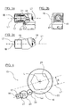
- Fig. 1 In the longitudinal direction, the housing 1 finds its rigid continuation down in a support tube 2, which is open at its bottom and is supported on that base 5, usually a machine part, on which also supports the nut 4 a screw.
- the support tube 2 of the tensioning device derives the tension reaction forces acting in the housing 1 on the solid base 5.
- the support tube 2 encloses and leaves room for the nut 4, without hindering a rotation of the arranged inside the support tube 2 nut 4.
- the nut 4 is screwed onto a threaded bolt 3 of the screw and secures it.
- a temporary train on the bolt 3 exerting element is provided with an internal thread 11 exchange socket 10 of the bolt tensioning device screwed onto the end portion A of the nut 4 beyond protruding threaded portion of the threaded bolt 3.
- against the exchange socket 10 is from below a in Fig. 1 supported only dashed reproduced piston 7.
- the piston 7 is longitudinally guided in the cylindrical interior of the hydraulic cylinder and sealed against this, and thus limits the hydraulic working space of the device. If the hydraulic working space is put under tensile force by means of a hydraulic supply 6, hydraulic pressure is exerted on the underside of the piston 7. This carries the interchangeable bush 10 supported on the piston 7, as a result of which the threaded bolt 3 is stretched slightly in the longitudinal direction.
- the housing 1 may form one, but also a plurality of hydraulic cylinders 1 connected in series one behind the other.
- Each hydraulic cylinder 1 encloses in each case a piston chamber and thus a hydraulic working space (not shown in the figures).
- a piston in the longitudinal direction L is arranged to be movable.
- the piston 7 or, in the case of a multi-part piston whose uppermost piston is coupled in such a manner with the interchangeable sleeve 10 in the longitudinal direction L that when lifting the piston, it comes to an identical movement and entrainment of the interchangeable sleeve 10, and thus to a torsion-free stretching of Threaded bolt 3.
- the screwed with the end portion A of the external thread of the threaded bolt 3 exchange socket 10 is designed to be interchangeable, so it can be exchanged if necessary for a replacement bushing 10 different size or geometry, whereas the one or more parts piston 7 does not have to be replaced with another piston ,
- the interchangeable sleeve 10 is screwed with its internal thread 11 on the threaded end A of the threaded bolt. Subsequent feeding of hydraulic pressure lifts the piston 1 guided in the cylinder 1 and supported from below against the interchangeable bushing 10, taking along the interchangeable bushing 10, resulting in longitudinal expansion of the threaded bolt 3. This is associated with a loss of friction on the underside of the nut 4, so that they now rotate by means of the gear assembly 15 on the thread of the bolt 3, z. B. can be tightened.
- the Fig. 2 indicates that the gear assembly 15 is laterally attached to the serving as a hydraulic cylinder housing 1 and / or on the support tube 2, that the axis of rotation L1 of a drive shaft 17, which is part of the gear assembly 15 is not parallel to the longitudinal center axis L of the piston , As Fig. 2 and Fig. 4 detect let the axis of rotation L1 does not intersect the longitudinal central axis L. Instead, the axis of rotation L1 extends tangentially and at a distance B to the longitudinal central axis L, ie between the axes L1 and L exists a minimum distance B. B is greater than zero, because the axes L1 and L do not intersect.
- FIGS. 3a to 3c show three different views of the gear assembly 15.
- the gear assembly 15 has a total of four partially intermeshing, operatively connected to each other Vernierungs institute 21, 22, 23, 24, of which Fig. 3a the first 21 and the third 23 as well as in Fig. 3c the fourth toothed element 24 can be seen.
- the toothed elements 21, 23 are arranged completely within a transmission housing 19 of the gear arrangement, one 24 only partially and one 22 completely outside.
- the first toothed element 21 is arranged on the end of the drive shaft 17 pointing into the interior of the gear housing 19 and designed as a drive bevel gear 21.
- the other end of the drive shaft 17 points out of the gearbox housing 19, where the drive shaft 17 is provided with an engagement structure 18 designed as an internal polygon.
- To the engagement structure 18 can be a corresponding external tool, for.
- the drive shaft 17 is mounted in the transmission housing 19.
- the formed as a drive bevel gear first toothing element 21 is in direct meshing with a trained as a further bevel gear third toothing element 23 whose axis of rotation is tilted by 90 ° to the axis of rotation L1, that it is arranged parallel to the longitudinal center axis L of the piston. Due to the pairing of the two bevel gearwheels 21 and 23, an angle ⁇ of 90 ° in this case is achieved.
- the further bevel gear 23 is toothed such that it is also suitable for engagement with a parallel rotating cylindrical gear.
- Such a cylindrical gear can be seen as the fourth toothed element 24.
- the fourth toothed element 24 protrudes on the side facing away from the engagement structure 18 of the transmission housing 19 partially out of this.
- This outstanding part of the fourth toothed element 24 designed as a cylindrical gear is dimensioned such that it passes through the opening 2A in the support tube 2 with the second toothed element 22 (FIG. Fig. 4 ) is in direct meshing.
- the second toothed element 22 is on the circumference of a driver element 16 (FIG. Fig. 1 . Figure 4 ) formed as a cylindrical toothing.
- the driver element 16 is located completely within the support tube 2 and is arranged in a form-fitting manner around the nut 4, so that a rotation of the driver element 16 leads to an identical rotation of the nut 4.
- the driver element 16 is annular and internally provided with a hexagon socket 27, which corresponds to the hexagon of the nut 3.
- Fig. 4 schematically shows the entire operative connection of the drive train formed by the gear assembly 15 for adjusting the nut 4.
- the drive shaft 17 is set in a clockwise rotation.
- the further bevel gear 23 which is therefore rotated about a tilted to the rotation axis L1 by 90 ° rotation axis in rotation, said axis of rotation is already aligned parallel to the axis of rotation of the nut 4 and the longitudinal center axis L of the piston.
- the further bevel gear 23 offset via the fourth gear member 24, the second toothed element 22 of the driver 16 in a clockwise rotation, and thus on the hexagon socket 27 and the nut 4th
Landscapes
- Engineering & Computer Science (AREA)
- Mechanical Engineering (AREA)
- Hand Tools For Fitting Together And Separating, Or Other Hand Tools (AREA)
- Gear Transmission (AREA)
- Devices For Conveying Motion By Means Of Endless Flexible Members (AREA)
Abstract
Description
- Die Erfindung betrifft eine Spannvorrichtung zum Dehnen eines Gewindebolzens durch Zug an dessen Gewindeendabschnitt, mit einem den Gewindeendabschnitt und eine auf den Gewindeendabschnitt aufgeschraubte Mutter umgebenden Stützrohr, einem in Verlängerung des Stützrohrs angeordneten Zylinder mit mindestens einem darin in Längsrichtung bewegbaren, mit einer Hydraulikversorgung verbindbaren Kolben, einer mit dem Gewindeendabschnitt verschraubbaren, durch den Kolben axial mitnehmbar ausgebildeten Wechselbuchse, und einer Getriebeanordnung zum Nachstellen der Mutter, wobei Bestandteile der Getriebeanordnung ein außen an der Mutter angreifendes Mitnehmerelement und eine mit einer Eingriffsstruktur für ein Antriebswerkzeug versehene Antriebswelle sind.
- Derartige Bolzenspannvorrichtungen, wie sie z. B. aus der
EP 1 784 283 B1 und derWO 99/46089 - Die Aufgabe der Erfindung ist es daher, eine Spannvorrichtung zu schaffen, die ein Arbeiten auch in solchen räumlich beengten Situationen erlaubt, in denen herkömmliche Spannvorrichtungen nicht einsetzbar sind.
- Zur Lösung dieser Aufgabe wird eine Spannvorrichtung zum Dehnen eines Gewindebolzens mit den Merkmalen des Patentanspruchs 1 vorgeschlagen.
- Bei dieser Spannvorrichtung ist die Drehachse der Antriebswelle in einem Winkel von mehr als 0° und weniger als 180°, vorzugsweise in einem Winkel von 90°, zur Längsmittelachse des Kolbens angeordnet.
- Da die Drehachse der Antriebswelle der Getriebeanordnung nicht parallel, sondern in einem Winkel zur Längsmittelachse des Kolbens angeordnet ist, kann die Mutter der Schraubverbindung über die schräg bzw. quer angeordnete Antriebswelle z. B. von einer weiter entfernten Position aus eingestellt werden. Unter Verwendung des externen Antriebswerkzeuges, z. B. eines Sechskantschlüssels, lässt sich daher die Mutter in bestimmten Montagesituationen von einer günstigeren, nämlich weniger beengten, besser zugänglichen oder schlicht bequemeren Position aus anziehen bzw. nachziehen.
- Mit einer Ausgestaltung wird vorgeschlagen, dass die Drehachse tangential und in einem Abstand zur Längsmittelachse des Kolbens verläuft. Eine derartige Anordnung bietet den Vorteil, die Spannvorrichtung auch in Montagesituationen verwenden zu können, in denen eine Anordnung, bei der die Drehachse der Antriebswelle die Längsmittelachse des Kolbens schneidet, nicht möglich ist, oder nur mit Nachteilen verbunden möglich ist.
- Vorzugsweise ist die Antriebswelle an ihrem der Eingriffsstruktur abgewandten Ende als ein erstes Verzahnungselement, und das Mitnehmerelement an seinem Umfang mit einem zweiten Verzahnungselement versehen, wobei das erste und das zweite Verzahnungselement in Wirkverbindung zueinander stehen. Dabei bedeutet "Wirkverbindung", dass die Verzahnungselemente entweder in unmittelbarem Eingriff miteinander stehen, oder die Wirkverbindung über weitere, zwischengeschaltete Elemente realisiert ist.
- Vorzugsweise ist das erste Verzahnungselement als Antriebskegelrad ausgebildet. Ein Kegelrad ermöglicht es auf eine einfache und zuverlässige Weise, dass die Drehachsen zweier unmittelbar miteinander in Eingriff stehender Verzahnungselemente zueinander im Winkel angeordnet, d. h. nicht parallel sind.
- Von Vorteil kann ferner sein, wenn weiterer Bestandteil der Getriebeanordnung ein zwischen dem ersten Verzahnungselement und dem zweiten Verzahnungselement angeordnetes drittes Verzahnungselement ist, das mit diesen beiden in Wirkverbindung steht und so zur
- Übertragung der Drehung der mit der Antriebsstruktur versehenen Antriebswelle auf das Mitnehmerelement angeordnet ist.
- Dabei wird vorgeschlagen, dass das dritte Verzahnungselement als ein mit dem Antriebskegelrad in Eingriff stehendes weiteres Kegelrad ausgebildet ist. Durch die sich somit ergebende Kegelradpaarung aus dem ersten und dem dritten Verzahnungselement wird eine konstruktiv einfache Drehachsenumlenkung erzielt.
- Zur Übertragung der Drehung der Antriebswelle auf das Mitnehmerelement ist gemäß einer weiteren Ausgestaltung zwischen dem weiteren Kegelrad und dem zweiten Verzahnungselement ein viertes mit diesen in Wirkverbindung stehendes und als weiteres Zylinderrad ausgebildetes Verzahnungselement angeordnet. Dieses zusätzliche Verzahnungselement kann so klein ausgebildet sein, dass es durch eine dafür vorgesehene seitliche Durchtrittsöffnung in dem Stützrohr hindurch mit dem zweiten Verzahnungselement in Eingriff steht.
- Ferner wird vorgeschlagen, dass das Mitnehmerelement mit einem Innenmehrkant zum Aufstülpen auf die Mutter versehen ist.
- Ferner wird vorgeschlagen, dass die Getriebeanordnung um die Drehachse des Mitnehmerelements herum verschwenkbar ausgestaltet ist und/oder dass die Getriebeanordnung um die Drehachse des vierten Verzahnungselements herum verschwenkbar ausgestaltet ist. Beide Maßnahmen ermöglichen einzeln oder zusammen eine individuelle Anpassung der Spannvorrichtung an spezielle Montagesituationen.
- Gemäß einer weiteren Ausgestaltung ist weiterer Bestandteil der Getriebeanordnung ein um die Antriebswelle angeordnetes ein- oder mehrteilig ausgebildetes Getriebegehäuse, wobei einfacherweise das Getriebegehäuse von außen an dem Stützrohr befestigt ist.
- Weitere Einzelheiten und Vorteile ergeben sich aus der nachfolgenden Beschreibung der auf der Zeichnung dargestellten Ausführungsbeispiele. Es zeigen:
- Fig. 1
- in einer Seitenansicht, bei der Bereiche der Getriebeanordnung und längs der Längsmittelachse geschnitten wiedergegeben sind, eine hydraulisch arbeitende Gewindebolzen-Spannvorrichtung mit einer seitlich daran befestigten Getriebeanordnung zum Einstellen einer Mutter, wobei die Gewindebolzen-Spannvorrichtung auf einen durch die Mutter gesicherten Gewindebolzen aufgesetzt ist;
- Fig. 2
- eine Draufsicht auf die Gewindebolzen-Spannvorrichtung der
Fig. 1 ; - Fig. 3a
- einen Teilschnitt durch die Getriebeanordnung;
- Fig. 3b
- eine Stirnansicht auf die Getriebeanordnung;
- Fig. 3c
- eine Draufsicht auf die Getriebeanordnung und
- Fig. 4
- eine schematische, getriebetechnische Darstellung des Getriebemechanismus zum Antreiben der Mutter.
-
Fig. 1 zeigt eine hydraulisch angetriebene Spannvorrichtung mit einem einen Hydraulikzylinder umschließenden starren Gehäuse 1. In Längsrichtung findet das Gehäuse 1 seine starre Fortsetzung nach unten in einem Stützrohr 2, welches an seiner Unterseite offen ist und sich auf jener Unterlage 5, zumeist einem Maschinenteil, abstützt, auf der sich auch die Mutter 4 einer Schraubverbindung abstützt. Das Stützrohr 2 der Spannvorrichtung leitet die im Gehäuse 1 wirkenden Spannreaktionskräfte auf die feste Unterlage 5 ab. Das Stützrohr 2 umschließt und lässt Platz für die Mutter 4, ohne ein Drehen der im Inneren des Stützrohrs 2 angeordneten Mutter 4 zu behindern. - Die Mutter 4 ist auf einen Gewindebolzen 3 der Schraubverbindung aufgeschraubt und sichert diesen. Als vorübergehend Zug auf den Bolzen 3 ausübendes Element wird eine mit einem Innengewinde 11 versehene Wechselbuchse 10 der Bolzenspannvorrichtung auf den Endabschnitt A des über die Mutter 4 hinaus überstehenden Gewindeabschnitts des Gewindebolzens 3 aufgeschraubt. Gegen die Wechselbuchse 10 ist von unten her ein in
Fig. 1 nur gestrichelt wiedergegebener Kolben 7 abgestützt. Der Kolben 7 ist in dem zylindrischen Innenraum des Hydraulikzylinders längsgeführt und diesem gegenüber abgedichtet, und begrenzt so den hydraulischen Arbeitsraum der Vorrichtung. Wird der hydraulische Arbeitsraum über eine Hydraulikversorgung 6 unter Zugkraft gesetzt, kommt es zu einem hydraulischen Druck auf die Unterseite des Kolbens 7. Dieser nimmt die am Kolben 7 abgestützte Wechselbuchse 10 mit, wodurch der Gewindebolzen 3 etwas in Längsrichtung gedehnt wird. - Über die sich seitlich an dem Gehäuse 1 befindende Hydraulikversorgung 6 sind ein oder auch mehrere in der Spannvorrichtung angeordnete Kolbenräume bzw. Arbeitsräume mit schaltbarem Hochdruck verbindbar.
- Außerdem ist eine durch eine Öffnung in dem Stützrohr 2 hindurch arbeitende Getriebeanordnung 15 vorgesehen, mit deren Hilfe sich die auf dem Gewindebolzen 3 sitzende Mutter 4 drehen lässt. Dieses Drehen ist nur möglich, wenn die Spannvorrichtung arbeitet, und daher die Mutter 4 nicht durch erhebliche Reibung, insbesondere gegenüber der Unterlage 5 und dem Gewinde des Bolzens 3, belastet ist.
- Das Gehäuse 1 kann einen, aber auch mehrere in Reihe hintereinander geschaltete Hydraulikzylinder 1 bilden. Jeder Hydraulikzylinder 1 umschließt dabei jeweils einen Kolbenraum und damit einen hydraulischen Arbeitsraum (in den Figuren nicht dargestellt). In jedem Kolbenraum ist, zu der Innenwandung des jeweiligen Gehäuseteils hin abgedichtet, ein Kolben in Längsrichtung L beweglich angeordnet. Beim Einschalten der Hydraulikversorgung 6 werden durch das Einspeisen von hydraulischem Druck in den bzw. die Kolbenräume der bzw. die darin angeordneten Kolben 7 angehoben. Der Kolben 7 bzw., im Falle eines mehrteiligen Kolbens, dessen oberster Kolben ist derart mit der Wechselbuchse 10 in Längsrichtung L bewegungsgekoppelt, dass beim Anheben des Kolbens es zu einer identischen Bewegung und Mitnahme der Wechselbuchse 10 kommt, und damit zu einem torsionsfreien Strecken des Gewindebolzens 3.
- Die mit dem Endabschnitt A des Außengewindes des Gewindebolzens 3 verschraubbare Wechselbuchse 10 ist austauschbar gestaltet, sie lässt sich also bei Bedarf gegen eine Wechselbuchse 10 anderer Größe bzw. Geometrie austauschen, wohingegen der ein- oder mehrteilige Kolben 7 nicht gegen einen anderen Kolben ausgetauscht werden muss.
- Zum Spannen des Gewindebolzens 3 wird zunächst die Wechselbuchse 10 mit ihrem Innengewinde 11 auf den Gewindeendabschnitt A des Gewindebolzens aufgeschraubt. Durch anschließendes Einspeisen von hydraulischem Druck hebt der im Zylinder 1 geführte und von unten gegen die Wechselbuchse 10 abgestützte Kolben 7 unter Mitnahme der Wechselbuchse 10 an, wodurch es zur Längsdehnung des Gewindebolzens 3 kommt. Damit verbunden ist ein Reibungsverlust an der Unterseite der Mutter 4, so dass diese sich jetzt mittels der Getriebeanordnung 15 auf dem Gewinde des Bolzens 3 drehen, z. B. nachziehen lässt.
- Die
Fig. 2 lässt erkennen, dass die Getriebeanordnung 15 seitlich derart an dem als Hydraulikzylinder dienenden Gehäuse 1 und/oder an dem Stützrohr 2 befestigt ist, dass die Drehachse L1 einer Antriebswelle 17, die Bestandteil der Getriebeanordnung 15 ist, nicht parallel zu der Längsmittelachse L des Kolbens verläuft. WieFig. 2 undFig. 4 erkennen lassen, schneidet die Drehachse L1 die Längsmittelachse L nicht. Stattdessen verläuft die Drehachse L1 tangential und in einem Abstand B zur Längsmittelachse L, d. h. zwischen den Achsen L1 und L existiert ein Mindestabstand B. B ist größer als Null, denn die Achsen L1 und L schneiden sich nicht. - Die
Fign. 3a bis 3c zeigen drei verschiedene Ansichten der Getriebeanordnung 15. Zum Einstellen der Mutter 4 durch die Öffnung 2A in dem Stützrohr 2 weist die Getriebeanordnung 15 insgesamt vier teilweise ineinandergreifende, miteinander in Wirkverbindung stehende Verzahnungselemente 21, 22, 23, 24 auf, von denen inFig. 3a das erste 21 und das dritte 23 sowie inFig. 3c das vierte Verzahnungselement 24 erkennbar ist. Die Verzahnungselemente 21, 23 sind vollständig innerhalb eines Getriebegehäuses 19 der Getriebeanordnung angeordnet, eines 24 nur zum Teil und eines 22 komplett außerhalb. - Das erste Verzahnungselement 21 ist an dem in das Innere des Getriebegehäuses 19 weisenden Ende der Antriebswelle 17 angeordnet und als Antriebskegelrad 21 ausgebildet. Das andere Ende der Antriebswelle 17 weist aus dem Getriebegehäuse 19 heraus, dort ist die Antriebswelle 17 mit einer als Innenmehrkant ausgebildeten Eingriffsstruktur 18 versehen. An die Eingriffsstruktur 18 lässt sich ein entsprechendes externes Werkzeug, z. B. ein Handwerkzeug, ansetzen, um so die Antriebswelle 17 um ihre Drehachse L1 zu drehen. Die Antriebswelle 17 ist in dem Getriebegehäuse 19 gelagert.
- Das als Antriebskegelrad ausgebildete erste Verzahnungselement 21 steht in unmittelbaren Zahneingriff mit einem als weiteres Kegelrad ausgebildeten dritten Verzahnungselement 23, dessen Drehachse derart um 90° zu der Drehachse L1 gekippt ist, dass sie parallel zu der Längsmittelachse L des Kolbens angeordnet ist. Durch die Paarung der beiden Kegelradzahnräder 21 und 23 wird ein Winkel Ω von in diesem Fall 90° erzielt. Das weitere Kegelrad 23 ist derart verzahnt, dass es sich gleichzeitig auch zum Eingriff mit einem parallel rotierenden Zylinderzahnrad eignet.
- In
Fig. 3c und schematisch inFig. 4 ist ein derartiges Zylinderzahnrad als viertes Verzahnungselement 24 erkennbar. Das vierte Verzahnungselement 24 ragt auf der der Eingriffsstruktur 18 abgewandten Seite des Getriebegehäuses 19 teilweise aus diesem heraus. Dieser herausragende Teil des als Zylinderzahnrad ausgebildeten, vierten Verzahnungselements 24 ist so dimensioniert, dass er durch die Öffnung 2A in dem Stützrohr 2 hindurch mit dem zweiten Verzahnungselement 22 (Fig. 4 ) in direktem Zahneingriff steht. Das zweite Verzahnungselement 22 ist am Umfang eines Mitnehmerelements 16 (Fig. 1 ,Fig.4 ) als zylindrische Verzahnung ausgebildet. Das Mitnehmerelement 16 befindet sich vollständig innerhalb des Stützrohrs 2 und ist formschlüssig um die Mutter 4 herum angeordnet, so dass eine Drehung des Mitnehmerelements 16 zu einer identischen Drehung der Mutter 4 führt. Dazu ist das Mitnehmerelement 16 ringförmig und innen mit einem Innensechskant 27 versehen, der zu dem Außensechskant der Mutter 3 korrespondiert. -
Fig. 4 zeigt schematisch die gesamte Wirkverbindung des durch die Getriebeanordnung 15 gebildeten Antriebsstranges zur Einstellung der Mutter 4. Um die Mutter 4 anzuziehen, wird über das mit der Eingriffsstruktur 18 korrespondierende und in die Eingriffsstruktur 18 eingeführte Werkzeug, z. B. eine Ratsche mit einem Außenvierkant, die Antriebswelle 17 in eine Rechtsdrehung versetzt. Mit der Antriebswelle 17 dreht sich das an dieser angeordneten Antriebskegelrad 21 identisch mit. In direktem Zahneingriff mit dem Antriebskegelrad 21 steht das weitere Kegelrad 23, welches daher um eine zu der Drehachse L1 um 90° gekippte Drehachse in Rotation versetzt wird, wobei diese Drehachse bereits parallel zur Drehachse der Mutter 4 und Längsmittelachse L des Kolbens ausgerichtet ist. Das weitere Kegelrad 23 versetzt über das vierte Verzahnungselement 24 die zweite Verzahnungselement 22 des Mitnehmerelements 16 in eine Rechtsdrehung, und somit über den Innensechskant 27 auch die Mutter 4. -
- 1
- Gehäuse/ Hydraulikzylinder
- 2
- Stützrohr
- 3
- Gewindebolzen
- 4
- Mutter
- 5
- Unterlage
- 6
- Hydraulikversorgung
- 7
- Kolben
- 10
- Wechselbuchse
- 11
- Innengewinde
- 15
- Getriebeanordnung
- 16
- Mitnehmerelement/ Innenmehrkant
- 17
- Antriebswelle
- 18
- Eingriffsstruktur
- 19
- Getriebegehäuse
- 21
- erstes Verzahnungselement
- 22
- zweites Verzahnungselement
- 23
- drittes Verzahnungselement
- 24
- viertes Verzahnungselement
- 27
- Innensechskant
- A
- Gewindeendabschnitt/ Endabschnitt
- B
- Abstand
- L
- Längsmittelachse
- L1
- Drehachse
- L2
- Drehachse
- Ω
- Winkel
Claims (11)
- Spannvorrichtung zum Dehnen eines Gewindebolzens durch Zug an dessen Gewindeendabschnitt (A), mit einem den Gewindeendabschnitt (A) und eine auf den Gewindeendabschnitt (A) aufgeschraubte Mutter (4) umgebenden Stützrohr (2), einem in Verlängerung des Stützrohrs (2) angeordneten Zylinder mit mindestens einem darin in Längsrichtung bewegbaren, mit einer Hydraulikversorgung verbindbaren Kolben (7), einer mit dem Gewindeendabschnitt (A) verschraubbaren, durch den Kolben (7) axial mitnehmbar ausgebildeten Wechselbuchse (10), und einer Getriebeanordnung (15) zum Nachstellen der Mutter (4), wobei Bestandteile der Getriebeanordnung (15) ein außen an der Mutter (4) angreifendes Mitnehmerelement (16) und eine mit einer Eingriffsstruktur (18) für ein Antriebswerkzeug versehene Antriebswelle (17) sind, dadurch gekennzeichnet, dass die Drehachse (L1) der Antriebswelle (17) in einem Winkel von mehr als 0° und weniger als 180°, vorzugsweise in einem Winkel von 90°, zur Längsmittelachse (L) des Kolbens (7) angeordnet ist.
- Spannvorrichtung nach Anspruch 1, dadurch gekennzeichnet, dass die Drehachse (L1) tangential und in einem Abstand (B) zur Längsmittelachse (L1) des Kolbens (7) verläuft.
- Spannvorrichtung nach Anspruch 1 oder 2, dadurch gekennzeichnet, dass die Antriebswelle (17) an ihrem der Eingriffsstruktur (18) abgewandten Ende als ein erstes Verzahnungselement (21) ausgebildet ist, und dass das Mitnehmerelement (16) an seinem Umfang als ein zweites Verzahnungselement (22) ausgebildet ist, wobei das erste und das zweite Verzahnungselement (21, 22) in Wirkverbindung zueinander stehen.
- Spannvorrichtung nach Anspruch 3, dadurch gekennzeichnet, dass das erste Verzahnungselement (21) als Antriebskegelrad ausgebildet ist.
- Spannvorrichtung nach Anspruch 3 oder 4, dadurch gekennzeichnet, dass weiterer Bestandteil der Getriebeanordnung (15) ein zwischen dem ersten Verzahnungselement (21) und dem zweiten Verzahnungselement (22) angeordnetes drittes, mit diesen beiden in Wirkverbindung stehendes Verzahnungselement (23) zur Übertragung einer Drehung der Antriebswelle (17) auf das Mitnehmerelement (16) ist.
- Spannvorrichtung nach Anspruch 5 i. V. m. Anspruch 4, dadurch gekennzeichnet, dass das dritte Verzahnungselement (23) als ein mit dem Antriebskegelrad (21) in Eingriff stehendes weiteres Kegelrad ausgebildet ist.
- Spannvorrichtung nach Anspruch 6, dadurch gekennzeichnet, dass zwischen dem weiteren Kegelrad (23) und dem zweiten Verzahnungselement (22) ein viertes mit diesen beiden in Eingriff stehendes und als weiteres Zylinderrad ausgebildetes Verzahnungselement (24) zur Übertragung der Drehung der Antriebswelle (17) auf das Mitnehmerelement (16) angeordnet ist.
- Spannvorrichtung nach einem der vorherigen Ansprüche, dadurch gekennzeichnet, dass das Mitnehmerelement (16) mit einem Innenmehrkant (27) zum Aufstülpen auf die Mutter (4) versehen ist.
- Spannvorrichtung nach einem der vorherigen Ansprüche, dadurch gekennzeichnet, dass die Getriebeanordnung (15) um die Längsmittelachse (L) des Kolbens (7) herum verschwenkbar ausgebildet ist.
- Spannvorrichtung nach einem der Ansprüche 7 bis 8, dadurch gekennzeichnet, dass die Getriebeanordnung (15) um die Drehachse (L2) des vierten Verzahnungselements (24) herum verschwenkbar ausgebildet ist.
- Spannvorrichtung nach einem der vorherigen Ansprüche, dadurch gekennzeichnet, dass weiterer Bestandteil der Getriebeanordnung (15) ein die Antriebswelle (17) aufnehmendes, ein- oder mehrteilig ausgebildetes Getriebegehäuse (19) ist, und dass das Getriebegehäuse (19) von außen gegen das Stützrohr (2) abgestützt ist.
Applications Claiming Priority (1)
| Application Number | Priority Date | Filing Date | Title |
|---|---|---|---|
| DE102013107096.5A DE102013107096A1 (de) | 2013-07-05 | 2013-07-05 | Spannvorrichtung zum Dehnen eines Gewindebolzens |
Publications (3)
| Publication Number | Publication Date |
|---|---|
| EP2821182A2 true EP2821182A2 (de) | 2015-01-07 |
| EP2821182A3 EP2821182A3 (de) | 2015-07-22 |
| EP2821182B1 EP2821182B1 (de) | 2017-09-06 |
Family
ID=50842064
Family Applications (1)
| Application Number | Title | Priority Date | Filing Date |
|---|---|---|---|
| EP14169565.0A Active EP2821182B1 (de) | 2013-07-05 | 2014-05-23 | Spannvorrichtung zum Dehnen eines Gewindebolzens |
Country Status (6)
| Country | Link |
|---|---|
| US (1) | US9623524B2 (de) |
| EP (1) | EP2821182B1 (de) |
| JP (1) | JP6376864B2 (de) |
| DE (1) | DE102013107096A1 (de) |
| DK (1) | DK2821182T3 (de) |
| ES (1) | ES2644708T3 (de) |
Cited By (4)
| Publication number | Priority date | Publication date | Assignee | Title |
|---|---|---|---|---|
| CN105881446A (zh) * | 2016-06-14 | 2016-08-24 | 广西玉柴机器股份有限公司 | 活塞装配工具 |
| CN108705486A (zh) * | 2018-07-15 | 2018-10-26 | 德州德劲液压动力有限公司 | 一种智能拉伸器 |
| CN110238642A (zh) * | 2019-07-15 | 2019-09-17 | 海盐东盛紧固件制造有限公司 | 一种螺栓螺母自动组装机 |
| CN113020938A (zh) * | 2021-04-01 | 2021-06-25 | 夏建明 | 一种汽车驱动轴总成制造成型加工工艺 |
Families Citing this family (2)
| Publication number | Priority date | Publication date | Assignee | Title |
|---|---|---|---|---|
| DE102019111185A1 (de) * | 2019-04-30 | 2020-11-05 | Frank Hohmann | Spannvorrichtung für eine Schraubverbindung |
| DE102021130441A1 (de) | 2021-11-22 | 2023-05-25 | Rolls-Royce Solutions GmbH | Messeinrichtung, System aus einem Schraubgerät und der Messeinrichtung und Verfahren zum Betreiben einer Messeinrichtung sowie Befestigungselement |
Citations (2)
| Publication number | Priority date | Publication date | Assignee | Title |
|---|---|---|---|---|
| WO1999046089A2 (de) | 1998-03-09 | 1999-09-16 | Carl Walter Schraubwerkzeug-Fabrik Gmbh & Co. Kg | Montageverfahren für zusammenzuspannende platten eines wärmetauschers |
| EP1784283B1 (de) | 2004-09-03 | 2009-09-30 | Jörg Hohmann | Hydraulische schraubenspannvorrichtung |
Family Cites Families (20)
| Publication number | Priority date | Publication date | Assignee | Title |
|---|---|---|---|---|
| US2885919A (en) * | 1954-07-08 | 1959-05-12 | Gen Motors Corp | Tool |
| US3015975A (en) * | 1959-11-17 | 1962-01-09 | Biach Ind | Bolt-tensioning apparatus |
| DE2258859A1 (de) * | 1972-12-01 | 1974-06-12 | Masch Und Bohrgeraete Fabrik | Hydraulische spannvorrichtung |
| JPS5182499A (ja) * | 1975-01-16 | 1976-07-20 | Osaka Jatsuki Seisakusho Kk | Kochoryokuborutotenshona |
| CS210710B1 (en) * | 1978-10-31 | 1982-01-29 | Jan Mlynarik | Hydraulic equipment for inducement of tractive forces |
| DE2852105A1 (de) * | 1978-11-30 | 1980-06-04 | Kraftwerk Union Ag | Vorrichtung zum drehen der muttern mehrerer, auf einem lochkreis angeordneter schraubenbolzen zum verschluss eines druckgefaesses, insbesondere eines reaktordruckgefaesses |
| DE4313778A1 (de) * | 1993-04-27 | 1994-11-03 | Westfalia Becorit Ind Tech | Schraubenspannvorrichtung |
| DE19638901C2 (de) * | 1996-09-23 | 2000-05-25 | Joerg Hohmann | Hydraulische Gewindebolzenspannvorrichtung |
| DE10145847C2 (de) * | 2001-09-17 | 2003-09-18 | Joerg Hohmann | Hydraulische Gewindebolzenspannvorrichtung und Verfahren zum Anziehen von grossen Schrauben mittels der hydraulischen Gewindebolzenspannvorrichtung |
| DE10339201B4 (de) * | 2003-08-22 | 2005-07-21 | Hohmann, Jörg | Doppelmutter zum kontrollierten Spannen eines Bauteils mittels Schraubenverbindung |
| FR2871231B1 (fr) * | 2004-06-02 | 2006-09-15 | Skf Ab | Procede de controle de la mise sous tension d'une tige, du type vis ou goujon d'assemblage, et dispositif de mise en oeuvre d'un tel procede |
| US8266781B2 (en) * | 2004-06-17 | 2012-09-18 | John Wentworth Bucknell | Hydraulic tensioning jacks |
| DE102004043145B3 (de) * | 2004-09-03 | 2006-05-18 | Hohmann, Jörg | Hydraulische Schraubenspannvorrichtung |
| DE102005015922B4 (de) * | 2005-04-06 | 2007-08-02 | Hohmann, Jörg | Hydraulische Gewindebolzenspannvorrichtung und Verfahren zum Anziehen von großen Schrauben mittels der hydraulischen Gewindebolzenspannvorrichtung |
| DE102007005284A1 (de) * | 2007-02-02 | 2008-08-07 | Wagner, Paul-Heinz | Verfahren zum Zusammenfügen von Bauteilen durch Spannbolzen |
| EP2346643B2 (de) * | 2008-11-14 | 2022-09-28 | Wagner Vermögensverwaltungs-GmbH & Co. KG | Schraubenspannvorrichtung |
| DE102009043907A1 (de) * | 2009-08-31 | 2011-03-03 | Frank Hohmann | Hydraulische Gewindebolzenspannvorrichtung und Verfahren zum großen Schrauben mittels der hydraulischen Gewindebolzenspannvorrichtung |
| DE102010006562B4 (de) * | 2010-02-02 | 2011-11-10 | Jörg Hohmann | Verfahren zum Spannen von Schraubenbolzen, sowie Schraubenbolzen und Schraubenbolzen-Spannvorrichtung zur Durchführung des Verfahrens |
| US20130008015A1 (en) * | 2010-02-08 | 2013-01-10 | Junkers John K | Apparatus and methods for tightening threaded fasteners |
| DE202012103565U1 (de) * | 2012-09-18 | 2012-10-08 | Jörg Hohmann | Spannvorrichtung zum Dehnen eines Gewindebolzens sowie hierfür geeignetes Werkzeug, vorzugsweise Antriebsadapter |
-
2013
- 2013-07-05 DE DE102013107096.5A patent/DE102013107096A1/de not_active Withdrawn
-
2014
- 2014-05-23 ES ES14169565.0T patent/ES2644708T3/es active Active
- 2014-05-23 DK DK14169565.0T patent/DK2821182T3/da active
- 2014-05-23 EP EP14169565.0A patent/EP2821182B1/de active Active
- 2014-07-04 US US14/324,106 patent/US9623524B2/en active Active
- 2014-07-04 JP JP2014138497A patent/JP6376864B2/ja active Active
Patent Citations (2)
| Publication number | Priority date | Publication date | Assignee | Title |
|---|---|---|---|---|
| WO1999046089A2 (de) | 1998-03-09 | 1999-09-16 | Carl Walter Schraubwerkzeug-Fabrik Gmbh & Co. Kg | Montageverfahren für zusammenzuspannende platten eines wärmetauschers |
| EP1784283B1 (de) | 2004-09-03 | 2009-09-30 | Jörg Hohmann | Hydraulische schraubenspannvorrichtung |
Cited By (5)
| Publication number | Priority date | Publication date | Assignee | Title |
|---|---|---|---|---|
| CN105881446A (zh) * | 2016-06-14 | 2016-08-24 | 广西玉柴机器股份有限公司 | 活塞装配工具 |
| CN108705486A (zh) * | 2018-07-15 | 2018-10-26 | 德州德劲液压动力有限公司 | 一种智能拉伸器 |
| CN108705486B (zh) * | 2018-07-15 | 2023-12-29 | 德州德劲液压动力有限公司 | 一种智能拉伸器 |
| CN110238642A (zh) * | 2019-07-15 | 2019-09-17 | 海盐东盛紧固件制造有限公司 | 一种螺栓螺母自动组装机 |
| CN113020938A (zh) * | 2021-04-01 | 2021-06-25 | 夏建明 | 一种汽车驱动轴总成制造成型加工工艺 |
Also Published As
| Publication number | Publication date |
|---|---|
| JP6376864B2 (ja) | 2018-08-22 |
| EP2821182A3 (de) | 2015-07-22 |
| DK2821182T3 (da) | 2017-12-04 |
| ES2644708T3 (es) | 2017-11-30 |
| US9623524B2 (en) | 2017-04-18 |
| DE102013107096A1 (de) | 2015-01-08 |
| JP2015013368A (ja) | 2015-01-22 |
| US20150013502A1 (en) | 2015-01-15 |
| EP2821182B1 (de) | 2017-09-06 |
Similar Documents
| Publication | Publication Date | Title |
|---|---|---|
| EP2821182B1 (de) | Spannvorrichtung zum Dehnen eines Gewindebolzens | |
| EP1784283B1 (de) | Hydraulische schraubenspannvorrichtung | |
| DE2033207C3 (de) | Druckluftschrauber | |
| EP0092127A2 (de) | Drehwerkzeug | |
| DE2102412C3 (de) | Verstellvorrichtung an Kurbelwellenschleifmaschinen zum Ausrichten der zu schleifenden Kurbelzapfen | |
| EP3546116A1 (de) | Vorrichtung zum anziehen von schraubverbindungen | |
| EP2708327B1 (de) | Spannvorrichtung zum Dehnen eines Gewindebolzens sowie hierfür geeignetes Werkzeug, vorzugsweise Antriebsadapter | |
| EP0320747B2 (de) | Pelletpresse | |
| EP0012101B1 (de) | Vorrichtung zum Drehen der zylindrischen Muttern mehrerer, auf einem Lochkreis angeordneter Schraubenbolzen zum Verschluss eines Druckgefässes, insbesondere eines Reaktordruckgefässes | |
| WO2017097735A1 (de) | Mutter, löseeinrichtung, spindelstütze und verfahren zur abstützung eines gegenstandes | |
| DE2805881C2 (de) | Spanndorn für die koaxiale Außenbearbeitung von Werkstücken mit Innenverzahnung | |
| EP2412478B1 (de) | Spannvorrichtung mit Kraftverstärkung | |
| DE10317342B4 (de) | Schnellspannsystem mit Handbetätigung | |
| EP2719504A1 (de) | Spannvorrichtung zum Dehnen eines Gewindebolzens | |
| DE2229073C2 (de) | Vorrichtung zum gleichzeitigen Spannen mehrerer Schraubenbolzen, Dehnschrauben, Zuganker oder dergleichen | |
| DE3318941A1 (de) | Vorrichtung zum drehen und axialbewegen von bolzen | |
| AT10324U1 (de) | Vorrichtung zum befestigen eines rotationswerkzeuges | |
| DE10207398B4 (de) | Getriebe | |
| DE102014107139A1 (de) | Hydraulische Spannvorrichtung | |
| DE102014014857B3 (de) | Kniehebelspannvorrichtung, insbesondere zur Verwendung im Karosseriebau der Kfz-Industrie | |
| DE3306809C1 (de) | Bohrgeraete | |
| EP3211286B1 (de) | Maschinenschuh und maschine | |
| DE2854182A1 (de) | Vorrichtung zum einstellen des stoesselhubes einer mechanischen presse | |
| EP3665001A1 (de) | Presse mit sensor zum messen der presskraft | |
| CH701403A1 (de) | Ratschenschlüssel mit Drehmomentverstärkung. |
Legal Events
| Date | Code | Title | Description |
|---|---|---|---|
| PUAI | Public reference made under article 153(3) epc to a published international application that has entered the european phase |
Free format text: ORIGINAL CODE: 0009012 |
|
| 17P | Request for examination filed |
Effective date: 20140523 |
|
| AK | Designated contracting states |
Kind code of ref document: A2 Designated state(s): AL AT BE BG CH CY CZ DE DK EE ES FI FR GB GR HR HU IE IS IT LI LT LU LV MC MK MT NL NO PL PT RO RS SE SI SK SM TR |
|
| AX | Request for extension of the european patent |
Extension state: BA ME |
|
| PUAL | Search report despatched |
Free format text: ORIGINAL CODE: 0009013 |
|
| AK | Designated contracting states |
Kind code of ref document: A3 Designated state(s): AL AT BE BG CH CY CZ DE DK EE ES FI FR GB GR HR HU IE IS IT LI LT LU LV MC MK MT NL NO PL PT RO RS SE SI SK SM TR |
|
| AX | Request for extension of the european patent |
Extension state: BA ME |
|
| RIC1 | Information provided on ipc code assigned before grant |
Ipc: B25B 29/02 20060101AFI20150617BHEP |
|
| R17P | Request for examination filed (corrected) |
Effective date: 20151012 |
|
| RBV | Designated contracting states (corrected) |
Designated state(s): AL AT BE BG CH CY CZ DE DK EE ES FI FR GB GR HR HU IE IS IT LI LT LU LV MC MK MT NL NO PL PT RO RS SE SI SK SM TR |
|
| GRAP | Despatch of communication of intention to grant a patent |
Free format text: ORIGINAL CODE: EPIDOSNIGR1 |
|
| STAA | Information on the status of an ep patent application or granted ep patent |
Free format text: STATUS: GRANT OF PATENT IS INTENDED |
|
| INTG | Intention to grant announced |
Effective date: 20170413 |
|
| GRAS | Grant fee paid |
Free format text: ORIGINAL CODE: EPIDOSNIGR3 |
|
| GRAA | (expected) grant |
Free format text: ORIGINAL CODE: 0009210 |
|
| STAA | Information on the status of an ep patent application or granted ep patent |
Free format text: STATUS: THE PATENT HAS BEEN GRANTED |
|
| AK | Designated contracting states |
Kind code of ref document: B1 Designated state(s): AL AT BE BG CH CY CZ DE DK EE ES FI FR GB GR HR HU IE IS IT LI LT LU LV MC MK MT NL NO PL PT RO RS SE SI SK SM TR |
|
| REG | Reference to a national code |
Ref country code: GB Ref legal event code: FG4D Free format text: NOT ENGLISH |
|
| REG | Reference to a national code |
Ref country code: CH Ref legal event code: EP Ref country code: AT Ref legal event code: REF Ref document number: 925356 Country of ref document: AT Kind code of ref document: T Effective date: 20170915 |
|
| REG | Reference to a national code |
Ref country code: IE Ref legal event code: FG4D Free format text: LANGUAGE OF EP DOCUMENT: GERMAN |
|
| REG | Reference to a national code |
Ref country code: DE Ref legal event code: R096 Ref document number: 502014005304 Country of ref document: DE |
|
| REG | Reference to a national code |
Ref country code: ES Ref legal event code: FG2A Ref document number: 2644708 Country of ref document: ES Kind code of ref document: T3 Effective date: 20171130 |
|
| REG | Reference to a national code |
Ref country code: DK Ref legal event code: T3 Effective date: 20171128 |
|
| REG | Reference to a national code |
Ref country code: NL Ref legal event code: MP Effective date: 20170906 |
|
| REG | Reference to a national code |
Ref country code: LT Ref legal event code: MG4D |
|
| PG25 | Lapsed in a contracting state [announced via postgrant information from national office to epo] |
Ref country code: LT Free format text: LAPSE BECAUSE OF FAILURE TO SUBMIT A TRANSLATION OF THE DESCRIPTION OR TO PAY THE FEE WITHIN THE PRESCRIBED TIME-LIMIT Effective date: 20170906 Ref country code: HR Free format text: LAPSE BECAUSE OF FAILURE TO SUBMIT A TRANSLATION OF THE DESCRIPTION OR TO PAY THE FEE WITHIN THE PRESCRIBED TIME-LIMIT Effective date: 20170906 Ref country code: FI Free format text: LAPSE BECAUSE OF FAILURE TO SUBMIT A TRANSLATION OF THE DESCRIPTION OR TO PAY THE FEE WITHIN THE PRESCRIBED TIME-LIMIT Effective date: 20170906 Ref country code: NO Free format text: LAPSE BECAUSE OF FAILURE TO SUBMIT A TRANSLATION OF THE DESCRIPTION OR TO PAY THE FEE WITHIN THE PRESCRIBED TIME-LIMIT Effective date: 20171206 Ref country code: SE Free format text: LAPSE BECAUSE OF FAILURE TO SUBMIT A TRANSLATION OF THE DESCRIPTION OR TO PAY THE FEE WITHIN THE PRESCRIBED TIME-LIMIT Effective date: 20170906 |
|
| PG25 | Lapsed in a contracting state [announced via postgrant information from national office to epo] |
Ref country code: RS Free format text: LAPSE BECAUSE OF FAILURE TO SUBMIT A TRANSLATION OF THE DESCRIPTION OR TO PAY THE FEE WITHIN THE PRESCRIBED TIME-LIMIT Effective date: 20170906 Ref country code: LV Free format text: LAPSE BECAUSE OF FAILURE TO SUBMIT A TRANSLATION OF THE DESCRIPTION OR TO PAY THE FEE WITHIN THE PRESCRIBED TIME-LIMIT Effective date: 20170906 Ref country code: BG Free format text: LAPSE BECAUSE OF FAILURE TO SUBMIT A TRANSLATION OF THE DESCRIPTION OR TO PAY THE FEE WITHIN THE PRESCRIBED TIME-LIMIT Effective date: 20171206 |
|
| PG25 | Lapsed in a contracting state [announced via postgrant information from national office to epo] |
Ref country code: NL Free format text: LAPSE BECAUSE OF FAILURE TO SUBMIT A TRANSLATION OF THE DESCRIPTION OR TO PAY THE FEE WITHIN THE PRESCRIBED TIME-LIMIT Effective date: 20170906 |
|
| PG25 | Lapsed in a contracting state [announced via postgrant information from national office to epo] |
Ref country code: RO Free format text: LAPSE BECAUSE OF FAILURE TO SUBMIT A TRANSLATION OF THE DESCRIPTION OR TO PAY THE FEE WITHIN THE PRESCRIBED TIME-LIMIT Effective date: 20170906 Ref country code: PL Free format text: LAPSE BECAUSE OF FAILURE TO SUBMIT A TRANSLATION OF THE DESCRIPTION OR TO PAY THE FEE WITHIN THE PRESCRIBED TIME-LIMIT Effective date: 20170906 Ref country code: CZ Free format text: LAPSE BECAUSE OF FAILURE TO SUBMIT A TRANSLATION OF THE DESCRIPTION OR TO PAY THE FEE WITHIN THE PRESCRIBED TIME-LIMIT Effective date: 20170906 |
|
| PG25 | Lapsed in a contracting state [announced via postgrant information from national office to epo] |
Ref country code: SK Free format text: LAPSE BECAUSE OF FAILURE TO SUBMIT A TRANSLATION OF THE DESCRIPTION OR TO PAY THE FEE WITHIN THE PRESCRIBED TIME-LIMIT Effective date: 20170906 Ref country code: SM Free format text: LAPSE BECAUSE OF FAILURE TO SUBMIT A TRANSLATION OF THE DESCRIPTION OR TO PAY THE FEE WITHIN THE PRESCRIBED TIME-LIMIT Effective date: 20170906 Ref country code: IT Free format text: LAPSE BECAUSE OF FAILURE TO SUBMIT A TRANSLATION OF THE DESCRIPTION OR TO PAY THE FEE WITHIN THE PRESCRIBED TIME-LIMIT Effective date: 20170906 Ref country code: EE Free format text: LAPSE BECAUSE OF FAILURE TO SUBMIT A TRANSLATION OF THE DESCRIPTION OR TO PAY THE FEE WITHIN THE PRESCRIBED TIME-LIMIT Effective date: 20170906 Ref country code: IS Free format text: LAPSE BECAUSE OF FAILURE TO SUBMIT A TRANSLATION OF THE DESCRIPTION OR TO PAY THE FEE WITHIN THE PRESCRIBED TIME-LIMIT Effective date: 20180106 |
|
| REG | Reference to a national code |
Ref country code: DE Ref legal event code: R097 Ref document number: 502014005304 Country of ref document: DE |
|
| PLBE | No opposition filed within time limit |
Free format text: ORIGINAL CODE: 0009261 |
|
| STAA | Information on the status of an ep patent application or granted ep patent |
Free format text: STATUS: NO OPPOSITION FILED WITHIN TIME LIMIT |
|
| 26N | No opposition filed |
Effective date: 20180607 |
|
| PG25 | Lapsed in a contracting state [announced via postgrant information from national office to epo] |
Ref country code: SI Free format text: LAPSE BECAUSE OF FAILURE TO SUBMIT A TRANSLATION OF THE DESCRIPTION OR TO PAY THE FEE WITHIN THE PRESCRIBED TIME-LIMIT Effective date: 20170906 |
|
| PG25 | Lapsed in a contracting state [announced via postgrant information from national office to epo] |
Ref country code: MT Free format text: LAPSE BECAUSE OF FAILURE TO SUBMIT A TRANSLATION OF THE DESCRIPTION OR TO PAY THE FEE WITHIN THE PRESCRIBED TIME-LIMIT Effective date: 20170906 |
|
| REG | Reference to a national code |
Ref country code: CH Ref legal event code: PL |
|
| REG | Reference to a national code |
Ref country code: BE Ref legal event code: MM Effective date: 20180531 |
|
| PG25 | Lapsed in a contracting state [announced via postgrant information from national office to epo] |
Ref country code: MC Free format text: LAPSE BECAUSE OF FAILURE TO SUBMIT A TRANSLATION OF THE DESCRIPTION OR TO PAY THE FEE WITHIN THE PRESCRIBED TIME-LIMIT Effective date: 20170906 |
|
| REG | Reference to a national code |
Ref country code: IE Ref legal event code: MM4A |
|
| PG25 | Lapsed in a contracting state [announced via postgrant information from national office to epo] |
Ref country code: CH Free format text: LAPSE BECAUSE OF NON-PAYMENT OF DUE FEES Effective date: 20180531 Ref country code: LI Free format text: LAPSE BECAUSE OF NON-PAYMENT OF DUE FEES Effective date: 20180531 |
|
| PG25 | Lapsed in a contracting state [announced via postgrant information from national office to epo] |
Ref country code: LU Free format text: LAPSE BECAUSE OF NON-PAYMENT OF DUE FEES Effective date: 20180523 |
|
| PG25 | Lapsed in a contracting state [announced via postgrant information from national office to epo] |
Ref country code: FR Free format text: LAPSE BECAUSE OF NON-PAYMENT OF DUE FEES Effective date: 20180531 Ref country code: IE Free format text: LAPSE BECAUSE OF NON-PAYMENT OF DUE FEES Effective date: 20180523 |
|
| PG25 | Lapsed in a contracting state [announced via postgrant information from national office to epo] |
Ref country code: BE Free format text: LAPSE BECAUSE OF NON-PAYMENT OF DUE FEES Effective date: 20180531 |
|
| PG25 | Lapsed in a contracting state [announced via postgrant information from national office to epo] |
Ref country code: TR Free format text: LAPSE BECAUSE OF FAILURE TO SUBMIT A TRANSLATION OF THE DESCRIPTION OR TO PAY THE FEE WITHIN THE PRESCRIBED TIME-LIMIT Effective date: 20170906 |
|
| PG25 | Lapsed in a contracting state [announced via postgrant information from national office to epo] |
Ref country code: PT Free format text: LAPSE BECAUSE OF FAILURE TO SUBMIT A TRANSLATION OF THE DESCRIPTION OR TO PAY THE FEE WITHIN THE PRESCRIBED TIME-LIMIT Effective date: 20170906 Ref country code: HU Free format text: LAPSE BECAUSE OF FAILURE TO SUBMIT A TRANSLATION OF THE DESCRIPTION OR TO PAY THE FEE WITHIN THE PRESCRIBED TIME-LIMIT; INVALID AB INITIO Effective date: 20140523 |
|
| PG25 | Lapsed in a contracting state [announced via postgrant information from national office to epo] |
Ref country code: CY Free format text: LAPSE BECAUSE OF FAILURE TO SUBMIT A TRANSLATION OF THE DESCRIPTION OR TO PAY THE FEE WITHIN THE PRESCRIBED TIME-LIMIT Effective date: 20170906 Ref country code: MK Free format text: LAPSE BECAUSE OF NON-PAYMENT OF DUE FEES Effective date: 20170906 Ref country code: GR Free format text: LAPSE BECAUSE OF FAILURE TO SUBMIT A TRANSLATION OF THE DESCRIPTION OR TO PAY THE FEE WITHIN THE PRESCRIBED TIME-LIMIT Effective date: 20170906 |
|
| PG25 | Lapsed in a contracting state [announced via postgrant information from national office to epo] |
Ref country code: AL Free format text: LAPSE BECAUSE OF FAILURE TO SUBMIT A TRANSLATION OF THE DESCRIPTION OR TO PAY THE FEE WITHIN THE PRESCRIBED TIME-LIMIT Effective date: 20170906 |
|
| REG | Reference to a national code |
Ref country code: AT Ref legal event code: MM01 Ref document number: 925356 Country of ref document: AT Kind code of ref document: T Effective date: 20190523 |
|
| PG25 | Lapsed in a contracting state [announced via postgrant information from national office to epo] |
Ref country code: AT Free format text: LAPSE BECAUSE OF NON-PAYMENT OF DUE FEES Effective date: 20190523 |
|
| REG | Reference to a national code |
Ref country code: DE Ref legal event code: R082 Ref document number: 502014005304 Country of ref document: DE Representative=s name: JANKE SCHOLL PATENTANWAELTE PARTG MBB, DE |
|
| P01 | Opt-out of the competence of the unified patent court (upc) registered |
Effective date: 20230530 |
|
| PGFP | Annual fee paid to national office [announced via postgrant information from national office to epo] |
Ref country code: DK Payment date: 20230524 Year of fee payment: 10 Ref country code: DE Payment date: 20220706 Year of fee payment: 10 |
|
| PGFP | Annual fee paid to national office [announced via postgrant information from national office to epo] |
Ref country code: GB Payment date: 20230524 Year of fee payment: 10 Ref country code: ES Payment date: 20230725 Year of fee payment: 10 |