EP2820931A1 - Soil working machine with an improved device for adjusting the working depth - Google Patents
Soil working machine with an improved device for adjusting the working depth Download PDFInfo
- Publication number
- EP2820931A1 EP2820931A1 EP14175439.0A EP14175439A EP2820931A1 EP 2820931 A1 EP2820931 A1 EP 2820931A1 EP 14175439 A EP14175439 A EP 14175439A EP 2820931 A1 EP2820931 A1 EP 2820931A1
- Authority
- EP
- European Patent Office
- Prior art keywords
- working
- machine according
- adjusting device
- transverse beam
- tools
- Prior art date
- Legal status (The legal status is an assumption and is not a legal conclusion. Google has not performed a legal analysis and makes no representation as to the accuracy of the status listed.)
- Granted
Links
- 239000002689 soil Substances 0.000 title claims description 18
- 208000032370 Secondary transmission Diseases 0.000 claims abstract description 21
- 238000003971 tillage Methods 0.000 claims abstract description 20
- 208000032369 Primary transmission Diseases 0.000 description 5
- 230000008901 benefit Effects 0.000 description 2
- 238000002513 implantation Methods 0.000 description 2
- 210000000056 organ Anatomy 0.000 description 2
- 238000009331 sowing Methods 0.000 description 2
- 241000272478 Aquila Species 0.000 description 1
- 238000005452 bending Methods 0.000 description 1
- 230000005540 biological transmission Effects 0.000 description 1
- 230000008878 coupling Effects 0.000 description 1
- 238000010168 coupling process Methods 0.000 description 1
- 238000005859 coupling reaction Methods 0.000 description 1
- 238000006073 displacement reaction Methods 0.000 description 1
- 238000005553 drilling Methods 0.000 description 1
- 230000000694 effects Effects 0.000 description 1
- 230000002349 favourable effect Effects 0.000 description 1
- 239000002184 metal Substances 0.000 description 1
- 230000004048 modification Effects 0.000 description 1
- 238000012986 modification Methods 0.000 description 1
- 238000011084 recovery Methods 0.000 description 1
- 238000006467 substitution reaction Methods 0.000 description 1
Images
Classifications
-
- A—HUMAN NECESSITIES
- A01—AGRICULTURE; FORESTRY; ANIMAL HUSBANDRY; HUNTING; TRAPPING; FISHING
- A01B—SOIL WORKING IN AGRICULTURE OR FORESTRY; PARTS, DETAILS, OR ACCESSORIES OF AGRICULTURAL MACHINES OR IMPLEMENTS, IN GENERAL
- A01B33/00—Tilling implements with rotary driven tools, e.g. in combination with fertiliser distributors or seeders, with grubbing chains, with sloping axles, with driven discs
- A01B33/08—Tools; Details, e.g. adaptations of transmissions or gearings
- A01B33/082—Transmissions; Gearings; Power distribution
- A01B33/085—Transmissions; Gearings; Power distribution specially adapted for tools on a vertical shaft
-
- A—HUMAN NECESSITIES
- A01—AGRICULTURE; FORESTRY; ANIMAL HUSBANDRY; HUNTING; TRAPPING; FISHING
- A01B—SOIL WORKING IN AGRICULTURE OR FORESTRY; PARTS, DETAILS, OR ACCESSORIES OF AGRICULTURAL MACHINES OR IMPLEMENTS, IN GENERAL
- A01B33/00—Tilling implements with rotary driven tools, e.g. in combination with fertiliser distributors or seeders, with grubbing chains, with sloping axles, with driven discs
- A01B33/06—Tilling implements with rotary driven tools, e.g. in combination with fertiliser distributors or seeders, with grubbing chains, with sloping axles, with driven discs with tools on vertical or steeply-inclined shaft
- A01B33/065—Tilling implements with rotary driven tools, e.g. in combination with fertiliser distributors or seeders, with grubbing chains, with sloping axles, with driven discs with tools on vertical or steeply-inclined shaft comprising a plurality of rotors carried by an elongate, substantially closed transmission casing, transversely connectable to a tractor
-
- A—HUMAN NECESSITIES
- A01—AGRICULTURE; FORESTRY; ANIMAL HUSBANDRY; HUNTING; TRAPPING; FISHING
- A01B—SOIL WORKING IN AGRICULTURE OR FORESTRY; PARTS, DETAILS, OR ACCESSORIES OF AGRICULTURAL MACHINES OR IMPLEMENTS, IN GENERAL
- A01B63/00—Lifting or adjusting devices or arrangements for agricultural machines or implements
- A01B63/02—Lifting or adjusting devices or arrangements for agricultural machines or implements for implements mounted on tractors
- A01B63/10—Lifting or adjusting devices or arrangements for agricultural machines or implements for implements mounted on tractors operated by hydraulic or pneumatic means
- A01B63/111—Lifting or adjusting devices or arrangements for agricultural machines or implements for implements mounted on tractors operated by hydraulic or pneumatic means regulating working depth of implements
Definitions
- the present invention relates to the general technical field of agricultural machinery and especially agricultural machinery for working the soil.
- the invention relates to a tillage machine comprising a frame with working tools and a reference member disposed at the rear of the working tools in view of the direction of advance, the chassis carrying at least one transverse beam on which is connected the reference member via two arms remote from each other, the working tools are distributed under the transverse beam and are rotated via a gearbox, a lateral housing and a shaft secondary transmission extending substantially horizontally and transversely to the direction of advance during work, a device for adjusting the working depth of the tools is provided between each arm and the transverse beam.
- the rotary harrow comprises a transverse beam with working tools and a reference member of the reboiling roller type disposed behind the working tools.
- the roller is attached to the transverse beam via two arms extending to the right and to the left of the lateral ends of the transverse beam.
- the rotary harrow is equipped with an adjustment device to position the working tools in height relative to the reference member. Such an adjustment device is associated with each arm.
- the position of the working tools relative to the roll is determined by the drilling of the hole sector in which the spindle is manually placed. The adjustment is done in steps, it is not continuous.
- the user wishes to change the setting of the working depth of the tools during work, it will be essential to get off the tractor to place the pin in another hole.
- the working depth adjustment device is hydraulic.
- the rotary harrow has a frame that supports two transverse beams under which are mounted the work tools. Behind the work tools is a roll of reconsolidation. Each roll is attached to the corresponding transverse beam by means of two arms spaced apart from each other.
- the adjustment of the working depth is effected by means of an adjusting device positioned centrally on each transverse beam.
- the adjusting device comprises a hydraulic cylinder. In this central zone, straddling the two transverse beams, is the gearbox which transmits the rotational movement to the working tools.
- This rotational movement is initiated by the PTO shaft of the tractor which drives a gearbox, which is connected by a secondary drive shaft to the side housing.
- the hydraulic cylinder is mounted on a support that spans the secondary drive shaft.
- the hydraulic cylinder is placed at the rear and above the cross beam.
- the implementation of the hydraulic cylinder is virtually vertical, the size of the adjustment device is relatively important. With such cumbersome adjustment devices on the tillage machine, it is not possible to mount a hopper or distribution heads equipping a drill on top of the transverse beams.
- the present invention aims to overcome the aforementioned drawbacks. In particular, it must offer an agricultural tillage machine with a less bulky working depth adjustment device.
- an important feature of the invention is that at least one adjusting device extends, in side view, substantially in front of a vertical plane passing through the center of the secondary transmission shaft, considering the direction in advance. Thanks to this characteristic, the adjustment device extends substantially above and in the front part of the transverse beam in a free space and especially without interference with the secondary transmission shaft.
- the adjustment device according to the invention therefore does not jig the secondary transmission shaft. As a result, the implantation of the adjustment device is compact.
- the size of the adjustment device is part of the size of the soil working machine.
- the adjustment device extends in the first third of the distance separating two vertical planes passing respectively through the axis of the front articulation of the arm and by the horizontal axis of the reference organ.
- the adjustment device is thus housed above the transverse beam.
- the adjustment device in its hydraulic version or in its manually adjustable version, can be completely housed in the volume, above the transverse beam, within the height limit of the lateral casing. There is no interference from the adjuster with the secondary drive shaft. The adjustment device does not interfere with the drive by the secondary drive shaft.
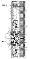
- FIG 1 there is a tillage machine (1) connected to the rear hitch (2) of a tractor.
- This tillage machine is intended for the preparation of seed beds. It comprises a chassis (3) with a frame (4) provided with a coupling system (5). In the example shown, it is a three point hitch system. It has two lower hitch points and an upper hitch point.
- the tractor is caused to move and animate the tillage machine (1) in a direction of advance indicated by the arrow (A).
- the tillage machine (1) also comprises working tools (6) and a reference member (7) implanted behind the working tools (6).
- the function of the reference member (7) is to control the working depth of the working tools (6).
- the tillage machine (1) of the figure 1 is a folding machine in two parts.
- the frame (3) thus carries two transverse beams (8) which extend transversely to the direction of advance (A) at work.
- the transverse beam (8) on the left is only partially shown and some working tools (6) have been shown in broken lines at the right transverse beam (8).
- Each transverse beam (8) is connected, via joints (9) of axes directed in the direction of advance (A), to the frame (3).
- These two transverse beams (8) are foldable upward for road transport.
- the folded position is obtained by means of actuators (10) articulated each between the frame (3) and the corresponding transverse beam (8).
- the actuator (10) is, for example, a double-acting hydraulic cylinder.
- Each transverse beam (8) is foldable substantially vertically for transport.
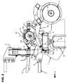
- the tillage machine (1) shown on the figure 2 , is a rotary harrow used for the superficial recovery of plowing and the preparation of seed beds.
- the working tools (6) extend under the transverse beams (8) and are mounted on rotors so as to be rotatable about respective vertically directed axes (12). Each rotor is equipped with two working tools (6) also called teeth.
- the power required for operation is provided by the tractor PTO shaft via a gearbox (14) and side housings (15).
- a side casing (15) is mounted directly on the corresponding transverse beam (8) and is positioned in the middle thereof. The lateral casing (15) thus extends above the working tools (6), in the space occupied by the soil working machine (1).
- the transverse beam (8) which is advantageously hollow.
- the transverse beam (8) has a lid assembled using fastening means such as bolts.
- a gear train rotates rotors on each side of the side casing (15).
- the lateral casing (15) is, for example, a bevel gearbox.
- a primary transmission shaft (13) provides the drive connection between the PTO shaft of the tractor and the gearbox (14).
- a secondary transmission shaft (16) connects each lateral housing (15) to the gearbox (14).
- the secondary transmission shafts (16) extend transversely and substantially horizontally with respect to the direction of advance (A) during the work.
- the gearbox (14) extends, in top view, in the middle of the frame (3) foldable and the secondary transmission shafts (16) are advantageously aligned.
- the primary transmission shaft (13) and the secondary transmission shaft (16) are universal joint drive shafts. It will be noted that elements of the rotary harrow have been removed to facilitate understanding.
- the reference organ (7) is a roller that has the function of pressing the ground, to complete the crumbling of the earth and to control the depth of work. It comprises a substantially cylindrical core with a horizontal axis (17) extending horizontally and preferably perpendicular to the direction of advance (A) during work. The roller is usually driven by the ground. A roll is implanted behind the working tools (6). As the frame (3) is collapsible, a roller is associated with each transverse beam (8). Each roll is attached to the corresponding transverse beam (8) via two arms (18) spaced apart from each other. The arms (18) extend to the right and to the left of the lateral ends of the transverse beam (8).
- Each arm (18) is pivotable and extends parallel to the direction of advance (A) during work.
- the front end of the arm (18) is connected to the transverse beam (8) by means of a front articulation (19).
- the axis of the front articulation (19) extends at least parallel to the horizontal axis (17) of the roller.
- the roll is guided in rotation and is pivotable about the horizontal axis (17).
- a device (20) for adjusting the working depth of the working tools (6) is provided between each of the arms (18) and the transverse beam (8).
- the function of the adjusting device (20) is to adjust the height position of the roller with respect to the transverse beam (8).
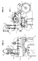
- the figure 3 represents, in a front view in perspective, the adjusting device (20) located in the vicinity of the central portion of the frame (3), at the level of the secondary transmission shaft (16).
- the actuator (10) is not represented on this figure 3 .
- the left support of the adjustment device (20) is partially represented.
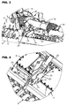
- the figure 4 represents, in a perspective view from above, an adjustment device located at the free end of the transverse beam (8).
- At least one adjusting device (20) of the working depth extends, in side view, substantially in front of a vertical plane (21) passing through the center of the secondary transmission shaft (16), taking into account the direction of advance (A).
- the arrangement of the parts constituting the adjustment device (20) is more compact and therefore more compact.
- the overall height, in working position, of the adjustment device (20) is reduced since it is not necessary to bypass the secondary transmission shaft (16).
- the size of the adjustment device is part of the size of the soil working machine (1).
- the adjustment device (20) is close to the front articulation (19) of the arm (18) which allows to have a large adjustment range with a limited stroke.
- the adjusting device (20) acts directly on the arm (18) of the reference member (7).
- the front articulation (19) extends forward of the vertical plane (21) and the reference member (7) extends behind the vertical plane (21).
- the tillage machine (1) has a working width of more than 3, 50 meters, it is therefore collapsible.
- This rotary harrow is powered by a powerful tractor.
- the position of the PTO shaft relative to the ground is relatively high since it is also equipped with large diameter wheels.
- the angle ( ⁇ ) of operation of the primary transmission shaft (13) must be low.
- This angle ( ⁇ ), represented on the figure 2 is the angle between the primary transmission shaft (13) and a horizontal plane.
- the gearbox (14) is offset backwards in view of the direction of advance (A) relative to the vertical axis (12) of rotation of the work tools (6). ).
- the length of the primary transmission shaft (13) is thus also increased.
- the vertical plane (21) passing through the center of the secondary transmission shaft (16) extends behind the vertical plane passing through the vertical axis (12) of rotation of the working tools (6) and that the axis of the front articulation (19) extends forward of the vertical axis (12) of rotation of the tools working (6).
- the vertical plane passing through the vertical axis (12) also corresponds to the plane of symmetry of the transverse beam (8).
- the roller rolls by leaning on the ground and thus determines the working depth of the work tools (6).
- the adjusting devices (20) of the working depth limit the displacement of the transverse beam (8) relative to the reference member (7) only downwards. In this way, the transverse beam (8) can move temporarily upwards, when the working tools (6) encounter an obstacle buried in the ground while the reference member (7) continues to roll on the ground.
- the roller shown in the figures also has the function of making grooves in the ground. It presents metal radial crowns made from segments that are assembled to each other. On other rollers, the crowns are made of rubber.
- the roller is provided with equidistant rings disposed on the cylindrical core.
- each adjusting device (20) of the working depth extends, in side view, substantially in front of a vertical plane (21) passing through the center of the secondary transmission shaft (16).
- the adjusting devices (20) mounted on the soil working machine (1) are identical.
- the small footprint of this tillage machine, in the direction of advance (A) allows to associate easily with a drill.
- the combination of a tillage machine (1) and a seed drill makes it possible to perform different tasks during a single passage on a parcel. The preparation of the seedbed and the sowing are done in a single pass, the duration of the work is reduced.
- the adjusting device (20) of the working depth extends in the first third of the distance separating two vertical planes passing respectively through the axis of the front articulation (19) of the arm (18) and the horizontal axis (17) of the reference member (7).
- the adjusting device (20) of the working depth is disposed close to the axis of the front joint (19).
- the adjustment device (20) of the working depth extends substantially between the front edge and the rear edge of the transverse beam (8) and in the limit in height of the lateral casing (15).
- the size of the adjustment device (20) is therefore part of the size of the soil working machine (1).
- the adjusting device (20) is positioned substantially in the lower quarter.
- At least one of the arms (18) consists of a central portion (22) and two wings (23) perpendicular to the ends of the central portion (22).
- An opening (24) is provided in the central portion (22) of the arm (18).
- the cross section of the arm (18) is advantageously H-shaped. With such a cross-section, the flexural strength of the arm (18) is increased when the transverse beams (8) are folded substantially vertically for transport. The flexural inertia is optimal with respect to the bending stresses generated by the vertical forces.
- the opening (24) in the central portion (22) allows on the one hand to reduce the weight of the arm (18) and on the other hand to access and use the hollow profile of the arm (18).
- the cross-section of the H-shaped arm (18) may be replaced by a U-shape or a closed profile composed of two central parts (22) and two wings (23).
- At least one adjusting device (20) for the working depth is hydraulic.
- the adjusting device (20) comprises inter alia an actuator preferably a hydraulic cylinder (25) single effect.
- the hydraulic cylinder is a double-acting cylinder.
- the hydraulic cylinder (25) controls the working depth. Thanks to the hydraulic cylinder (25), the adjustment of the working depth can be realized from the tractor cab and is done continuously. The adjustment can especially be refined during the work and thus be adapted according to the working conditions and in particular according to the type of soil.
- the adjusting device (20) is also designed to allow upward movement of the transverse beam (8) when the working tools (6) encounter an obstacle buried in the ground while the reference member (7) remains in contact with the ground.
- each adjustment device (20) of the working depth is hydraulic and has a hydraulic cylinder (25). The same adjustment will then be done simultaneously for all the arms (18) so as to obtain a homogeneous working depth
- the arm (18) has an opening (24).
- This opening (24) is such that it allows the passage of the hydraulic cylinder (25), including its rod through the arm (18). This reduces the overall height of the hydraulic adjustment device (20).
- the adjustment device (20) is therefore more compact.
- the point of articulation of the hydraulic cylinder (25) at its stem is fixed and is guided in a groove (26).
- the groove (26) is oblong.
- the groove (26) has a circular arc shape whose center is the axis of the front articulation (19).
- the adjusting device (20) is close to the front articulation (19), so a change in length of a few centimeters of the hydraulic cylinder (25) will result in a rotation of several degrees of the reference member (7) around of the front articulation (19).
- the other point of articulation of the hydraulic cylinder (25) extends on the cylinder body near the rod. With such implantation of the hydraulic cylinder (25), the overall height of the adjustment device (20) is further reduced.
- the adjusting device (20) extends substantially in the lower front quarter of the secondary transmission shaft (16).
- the lower front quarter is defined by the vertical plane (21) and the horizontal plane passing through the center of the secondary transmission shaft (16).
- the groove (26) is positioned in the front and bottom quarter of the secondary drive shaft (16).
- the adjustment device (20) of the working depth is manual.
- the hydraulic cylinder (25) is replaced by a sector with holes and a pin to be placed in one of the holes.
- this manual adjustment device can be placed instead of the hydraulic adjustment device. Its overall height is even reduced.
- the manual adjustment device does not interfere with the drive with the secondary drive shaft (16).
- the various bores extend in the front quarter and lower of the secondary transmission shaft (16).
- the frame (3) carries three transverse beams (8), namely a central beam and two lateral beams.
- the lateral beams are hinged on either side of the central beam according to articulation axes directed substantially in the direction of advance (A).
- the side beams can be folded upward for transport by means of actuators (10).
- the soil working machine is made in the form of a rotary cutter.
- the rotary cutter has a frame consisting of at least one transverse beam made in the form of a box. It comprises working tools mounted on a rotor driven in rotation about a substantially horizontal axis.
- the rotor consists of a tube on which flanges are fixed at regular intervals. Each flange supports four work tools that loosen the ground.
- a roller extends to the rear of the rotor that crushes the clods, cups and evenes a strip of land for sowing. This roller makes it possible to determine the working depth of the rotor and therefore of the working tools.
- An adjusting device according to the invention extends between the roller and the transverse beam carrying the rotor. The roller is connected to the frame and in particular to the transverse beam by means of two arms. The rear ends of the arms rotate the roller about its substantially horizontal axis and transverse to the direction of advance (A).
Landscapes
- Life Sciences & Earth Sciences (AREA)
- Engineering & Computer Science (AREA)
- Mechanical Engineering (AREA)
- Soil Sciences (AREA)
- Environmental Sciences (AREA)
- Power Engineering (AREA)
- Soil Working Implements (AREA)
- Agricultural Machines (AREA)
Abstract
La présente invention concerne une machine de travail du sol (1) comportant un châssis (3) avec des outils de travail (6) et un organe de référence (7) disposé à l'arrière des outils de travail (6) compte tenu du sens d'avance (A), le châssis (3) portant au moins une poutre transversale (8) sur laquelle est relié l'organe de référence (7) par l'intermédiaire de deux bras (18) distants l'un de l'autre, les outils de travail (6) sont répartis sous la poutre transversale (8) et sont entraînés en rotation via un carter de renvoi (14), un carter latéral (15) et un arbre de transmission secondaire (16) s'étendant sensiblement horizontalement et transversalement par rapport au sens d'avance (A) pendant le travail, un dispositif de réglage (20) de la profondeur de travail des outils de travail (6) est prévu entre chaque bras (18) et la poutre transversale (8). La machine de travail du sol est remarquable en ce qu'au moins un dispositif de réglage (20) de la profondeur de travail s'étend, en vue de côté, sensiblement en avant d'un plan vertical (21) passant par le centre de l'arbre de transmission secondaire (16), compte tenu du sens d'avance (A).The present invention relates to a tillage machine (1) comprising a frame (3) with working tools (6) and a reference member (7) disposed at the rear of the working tools (6) taking into account the direction of advance (A), the frame (3) carrying at least one transverse beam (8) to which is connected the reference member (7) via two arms (18) distant one of the further, the working tools (6) are distributed under the transverse beam (8) and are rotated through a gearbox (14), a lateral housing (15) and a secondary drive shaft (16). extending substantially horizontally and transversely to the direction of feed (A) during work, an adjusting device (20) for the working depth of the working tools (6) is provided between each arm (18) and the transverse beam (8). The tillage machine is remarkable in that at least one adjusting device (20) for the working depth extends, in side view, substantially in front of a vertical plane (21) passing through the center of the secondary transmission shaft (16), taking into account the direction of advance (A).
Description
La présente invention se rapporte au domaine technique général du machinisme agricole et notamment aux machines agricoles destinées à travailler le sol. L'invention concerne une machine de travail du sol comportant un châssis avec des outils de travail et un organe de référence disposé à l'arrière des outils de travail compte tenu du sens d'avance, le châssis portant au moins une poutre transversale sur laquelle est relié l'organe de référence par l'intermédiaire de deux bras distants l'un de l'autre, les outils de travail sont répartis sous la poutre transversale et sont entraînés en rotation via un carter de renvoi, un carter latéral et un arbre de transmission secondaire s'étendant sensiblement horizontalement et transversalement par rapport au sens d'avance pendant le travail, un dispositif de réglage de la profondeur de travail des outils est prévu entre chaque bras et la poutre transversale.The present invention relates to the general technical field of agricultural machinery and especially agricultural machinery for working the soil. The invention relates to a tillage machine comprising a frame with working tools and a reference member disposed at the rear of the working tools in view of the direction of advance, the chassis carrying at least one transverse beam on which is connected the reference member via two arms remote from each other, the working tools are distributed under the transverse beam and are rotated via a gearbox, a lateral housing and a shaft secondary transmission extending substantially horizontally and transversely to the direction of advance during work, a device for adjusting the working depth of the tools is provided between each arm and the transverse beam.
Une machine de ce type est connue par le document
Sur la herse rotative repliable AQUILA RAPIDO présentée dans le prospectus "Herse rotative pliable" de Maschio Gaspardo S.p.A. du 11-2010, le dispositif de réglage de la profondeur de travail est hydraulique. La herse rotative comporte un châssis qui supporte deux poutres transversales sous lesquelles sont montés les outils de travail. Derrière les outils de travail est disposé un rouleau de rappuyage. Chaque rouleau est fixé sur la poutre transversale correspondante au moyen de deux bras distants l'un de l'autre. Le réglage de la profondeur de travail est effectué au moyen d'un dispositif de réglage positionné de manière centrale sur chaque poutre transversale. Le dispositif de réglage comporte un vérin hydraulique. Dans cette zone centrale, à cheval au-dessus des deux poutres transversales, se trouve le carter de renvoi qui transmet le mouvement de rotation aux outils de travail. Ce mouvement de rotation est initié par l'arbre de prise de force du tracteur qui entraîne un carter de renvoi, lequel est relié par un arbre de transmission secondaire au carter latéral. Le vérin hydraulique est monté sur un support qui enjambe l'arbre de transmission secondaire. Le vérin hydraulique est placé à l'arrière et au-dessus de la poutre transversale. L'implantation du vérin hydraulique est pratiquement verticale, l'encombrement du dispositif de réglage est donc relativement important. Avec de tels dispositifs de réglage encombrant sur la machine de travail du sol, il n'est pas possible de monter une trémie ou des têtes de distribution équipant un semoir au-dessus des poutres transversales.On the folding power harrow AQUILA RAPIDO presented in the brochure "Folding rotary harrow" of Maschio Gaspardo SpA from 11-2010, the working depth adjustment device is hydraulic. The rotary harrow has a frame that supports two transverse beams under which are mounted the work tools. Behind the work tools is a roll of reconsolidation. Each roll is attached to the corresponding transverse beam by means of two arms spaced apart from each other. The adjustment of the working depth is effected by means of an adjusting device positioned centrally on each transverse beam. The adjusting device comprises a hydraulic cylinder. In this central zone, straddling the two transverse beams, is the gearbox which transmits the rotational movement to the working tools. This rotational movement is initiated by the PTO shaft of the tractor which drives a gearbox, which is connected by a secondary drive shaft to the side housing. The hydraulic cylinder is mounted on a support that spans the secondary drive shaft. The hydraulic cylinder is placed at the rear and above the cross beam. The implementation of the hydraulic cylinder is virtually vertical, the size of the adjustment device is relatively important. With such cumbersome adjustment devices on the tillage machine, it is not possible to mount a hopper or distribution heads equipping a drill on top of the transverse beams.
La présente invention a pour but de remédier aux inconvénients précités. Elle doit notamment proposer une machine agricole de travail du sol avec un dispositif de réglage de profondeur de travail moins encombrant.The present invention aims to overcome the aforementioned drawbacks. In particular, it must offer an agricultural tillage machine with a less bulky working depth adjustment device.
A cet effet, une importante caractéristique de l'invention consiste en ce que au moins un dispositif de réglage s'étend, en vue de côté, sensiblement en avant d'un plan vertical passant par le centre de l'arbre de transmission secondaire, compte tenu de la direction d'avance. Grâce à cette caractéristique, le dispositif de réglage s'étend sensiblement au-dessus et dans la partie frontale de la poutre transversale dans un espace libre et surtout sans interférence avec l'arbre de transmission secondaire. Le dispositif de réglage selon l'invention n'enjambe donc pas l'arbre de transmission secondaire. De ce fait, l'implantation du dispositif de réglage est compacte. L'encombrement du dispositif de réglage s'inscrit dans l'encombrement de la machine de travail du sol.For this purpose, an important feature of the invention is that at least one adjusting device extends, in side view, substantially in front of a vertical plane passing through the center of the secondary transmission shaft, considering the direction in advance. Thanks to this characteristic, the adjustment device extends substantially above and in the front part of the transverse beam in a free space and especially without interference with the secondary transmission shaft. The adjustment device according to the invention therefore does not jig the secondary transmission shaft. As a result, the implantation of the adjustment device is compact. The size of the adjustment device is part of the size of the soil working machine.
Selon une autre caractéristique de l'invention, le dispositif de réglage s'étend dans le premier tiers de la distance séparant deux plans verticaux passant respectivement par l'axe de l'articulation avant du bras et par l'axe horizontal de l'organe de référence. Le dispositif de réglage est donc logé au-dessus de la poutre transversale.According to another characteristic of the invention, the adjustment device extends in the first third of the distance separating two vertical planes passing respectively through the axis of the front articulation of the arm and by the horizontal axis of the reference organ. The adjustment device is thus housed above the transverse beam.
Le dispositif de réglage, dans sa version hydraulique ou dans sa version à réglage manuel, peut être totalement logé dans le volume, au-dessus de la poutre transversale, dans la limite de hauteur du carter latéral. Il n'y a pas d'interférence du dispositif de réglage avec l'arbre de transmission secondaire. Le dispositif de réglage ne gêne pas l'entraînement par l'arbre de transmission secondaire.The adjustment device, in its hydraulic version or in its manually adjustable version, can be completely housed in the volume, above the transverse beam, within the height limit of the lateral casing. There is no interference from the adjuster with the secondary drive shaft. The adjustment device does not interfere with the drive by the secondary drive shaft.
D'autres caractéristiques et avantages de l'invention se dégageront de la description qui va suivre en regard des dessins annexés qui ne sont donnés qu'à titre d'exemples non limitatifs de l'invention. Sur ces dessins :
- la
figure 1 représente une vue de dessus d'une machine de travail du sol en deux parties conforme à l'invention, - la
figure 2 représente une vue de côté de la machine de travail du sol de lafigure 1 , - la
figure 3 représente une vue avant en perspective d'un dispositif de réglage selon l'invention au niveau d'un arbre de transmission secondaire, - la
figure 4 représente une vue de dessus en perspective d'un dispositif de réglage selon l'invention, - la
figure 5 représente une vue partielle en coupe selon l'axe V-V de lafigure 1 , - la
figure 6 représente une vue de côté d'une machine de travail du sol selon un autre exemple de réalisation.
- the
figure 1 represents a top view of a two-part tillage machine according to the invention, - the
figure 2 represents a side view of the tillage machine of thefigure 1 , - the
figure 3 represents a front perspective view of an adjusting device according to the invention at a secondary transmission shaft, - the
figure 4 represents a perspective top view of an adjusting device according to the invention, - the
figure 5 represents a partial view in section along the axis VV of thefigure 1 , - the
figure 6 represents a side view of a tillage machine according to another embodiment.
Sur la
La machine de travail du sol (1) de la
La machine de travail du sol (1), représentée sur la
L'organe de référence (7), représenté sur les
Selon une importante caractéristique de l'invention, au moins un dispositif de réglage (20) de la profondeur de travail s'étend, en vue de côté, sensiblement en avant d'un plan vertical (21) passant par le centre de l'arbre de transmission secondaire (16), compte tenu du sens d'avance (A). Avec une telle implantation, la disposition des pièces, constituant le dispositif de réglage (20), est plus ramassé et donc plus compact. L'encombrement en hauteur, en position travail, du dispositif de réglage (20) est réduit puisqu'il n'est pas nécessaire de contourner l'arbre de transmission secondaire (16). L'encombrement du dispositif de réglage s'inscrit dans l'encombrement de la machine de travail du sol (1). Grâce à cette caractéristique, le dispositif de réglage (20) se trouve proche de l'articulation avant (19) du bras (18) ce qui permet d'avoir une plage de réglage importante avec une course limitée. Le dispositif de réglage (20) agit directement sur le bras (18) de l'organe de référence (7). L'articulation avant (19) s'étend à l'avant du plan vertical (21) et l'organe de référence (7) s'étend à l'arrière du plan vertical (21).According to an important feature of the invention, at least one adjusting device (20) of the working depth extends, in side view, substantially in front of a vertical plane (21) passing through the center of the secondary transmission shaft (16), taking into account the direction of advance (A). With such an implementation, the arrangement of the parts constituting the adjustment device (20) is more compact and therefore more compact. The overall height, in working position, of the adjustment device (20) is reduced since it is not necessary to bypass the secondary transmission shaft (16). The size of the adjustment device is part of the size of the soil working machine (1). With this feature, the adjustment device (20) is close to the front articulation (19) of the arm (18) which allows to have a large adjustment range with a limited stroke. The adjusting device (20) acts directly on the arm (18) of the reference member (7). The front articulation (19) extends forward of the vertical plane (21) and the reference member (7) extends behind the vertical plane (21).
Dans l'exemple de réalisation représenté aux
Au travail, le rouleau roule en s'appuyant sur le sol et détermine ainsi la profondeur de travail des outils de travail (6). Durant le travail, les dispositifs de réglage (20) de la profondeur de travail limitent le déplacement de la poutre transversale (8) par rapport à l'organe de référence (7) uniquement vers le bas. De cette manière, la poutre transversale (8) peut se déplacer provisoirement vers le haut, lorsque les outils de travail (6) rencontrent un obstacle enfoui dans le sol pendant que l'organe de référence (7) continue à rouler sur le sol. Le rouleau représenté sur les figures a également pour fonction de réaliser des sillons dans la terre. Il présente des couronnes radiales métalliques réalisées à partir de segments qui sont assemblés les uns aux autres. Sur d'autres rouleaux, les couronnes sont en caoutchouc. Dans un autre exemple de réalisation, le rouleau est muni de couronnes équidistantes disposées sur l'âme cylindrique.At work, the roller rolls by leaning on the ground and thus determines the working depth of the work tools (6). During work, the adjusting devices (20) of the working depth limit the displacement of the transverse beam (8) relative to the reference member (7) only downwards. In this way, the transverse beam (8) can move temporarily upwards, when the working tools (6) encounter an obstacle buried in the ground while the reference member (7) continues to roll on the ground. The roller shown in the figures also has the function of making grooves in the ground. It presents metal radial crowns made from segments that are assembled to each other. On other rollers, the crowns are made of rubber. In another embodiment, the roller is provided with equidistant rings disposed on the cylindrical core.
De manière préférentielle, chaque dispositif de réglage (20) de la profondeur de travail s'étend, en vue de côté, sensiblement en avant d'un plan vertical (21) passant par le centre de l'arbre de transmission secondaire (16), compte tenu du sens d'avance (A). De façon avantageuse, les dispositifs de réglage (20) montés sur la machine de travail du sol (1) sont identiques. De plus, le faible encombrement de cette machine de travail du sol, dans le sens d'avance (A), permet de l'associer facilement à un semoir. La combinaison d'une machine de travail du sol (1) et d'un semoir permet d'accomplir différentes tâches lors d'un unique passage sur une parcelle. La préparation du lit de semence et le semis sont réalisés en un seul passage, la durée du chantier est donc réduit.Preferably, each adjusting device (20) of the working depth extends, in side view, substantially in front of a vertical plane (21) passing through the center of the secondary transmission shaft (16). , considering the direction of advance (A). Advantageously, the adjusting devices (20) mounted on the soil working machine (1) are identical. In addition, the small footprint of this tillage machine, in the direction of advance (A), allows to associate easily with a drill. The combination of a tillage machine (1) and a seed drill makes it possible to perform different tasks during a single passage on a parcel. The preparation of the seedbed and the sowing are done in a single pass, the duration of the work is reduced.
Selon une autre caractéristique de l'invention, le dispositif de réglage (20) de la profondeur de travail s'étend dans le premier tiers de la distance séparant deux plans verticaux passant respectivement par l'axe de l'articulation avant (19) du bras (18) et par l'axe horizontal (17) de l'organe de référence (7). Grâce à cette caractéristique, le dispositif de réglage (20) de la profondeur de travail est disposé proche de l'axe de l'articulation avant (19). A la lumière de la
A la lumière des
D'une manière avantageuse, et tel que représenté sur les
D'une manière particulièrement avantageuse, chaque dispositif de réglage (20) de la profondeur de travail est hydraulique et présente un vérin hydraulique (25). Le même réglage se fera alors de manière simultanée pour tous les bras (18) de manière à obtenir une profondeur de travail homogèneIn a particularly advantageous manner, each adjustment device (20) of the working depth is hydraulic and has a hydraulic cylinder (25). The same adjustment will then be done simultaneously for all the arms (18) so as to obtain a homogeneous working depth
D'après la
Selon une alternative représentée à la
Selon un exemple de réalisation non représenté, le châssis (3) porte trois poutres transversales (8), à savoir une poutre centrale et deux poutres latérales. Les poutres latérales sont articulées de part et d'autre de la poutre centrale selon des axes d'articulation dirigés sensiblement suivant le sens d'avance (A). Les poutres latérales peuvent être repliées vers le haut au transport au moyen d'actionneurs (10).According to an embodiment not shown, the frame (3) carries three transverse beams (8), namely a central beam and two lateral beams. The lateral beams are hinged on either side of the central beam according to articulation axes directed substantially in the direction of advance (A). The side beams can be folded upward for transport by means of actuators (10).
Selon un autre exemple de réalisation non représenté, la machine de travail du sol est réalisée sous la forme d'une fraise rotative. La fraise rotative présente un châssis constitué d'au moins une poutre transversale réalisée sous la forme d'un caisson. Elle comporte des outils de travail montés sur un rotor entraîné en rotation autour d'un axe sensiblement horizontal. Le rotor est constitué d'un tube sur lequel des flasques sont fixés à intervalles réguliers. Chaque flasque supporte quatre outils de travail qui ameublissent la terre. Un rouleau s'étend à l'arrière du rotor qui écrase les mottes, tasse et égalise une bande de terre en vue de travaux de semis. Ce rouleau permet de déterminer la profondeur de travail du rotor et donc des outils de travail. Un dispositif de réglage, selon l'invention, s'étend entre le rouleau et la poutre transversale portant le rotor. Le rouleau est lié au châssis et notamment à la poutre transversale au moyen de deux bras. Les extrémités arrière des bras guident en rotation le rouleau autour de son axe sensiblement horizontal et transversal au sens d'avance (A).According to another embodiment not shown, the soil working machine is made in the form of a rotary cutter. The rotary cutter has a frame consisting of at least one transverse beam made in the form of a box. It comprises working tools mounted on a rotor driven in rotation about a substantially horizontal axis. The rotor consists of a tube on which flanges are fixed at regular intervals. Each flange supports four work tools that loosen the ground. A roller extends to the rear of the rotor that crushes the clods, cups and evenes a strip of land for sowing. This roller makes it possible to determine the working depth of the rotor and therefore of the working tools. An adjusting device according to the invention extends between the roller and the transverse beam carrying the rotor. The roller is connected to the frame and in particular to the transverse beam by means of two arms. The rear ends of the arms rotate the roller about its substantially horizontal axis and transverse to the direction of advance (A).
Il est bien évident que l'invention n'est pas limitée au mode de réalisation décrit ci-dessus et représenté sur les dessins annexés. Des modifications restent possibles, notamment en ce qui concerne la constitution ou le nombre des divers éléments ou par substitution d'équivalents techniques, sans pour autant sortir du domaine de protection tel qu'il est défini par les revendications suivantes.It is obvious that the invention is not limited to the embodiment described above and shown in the accompanying drawings. Modifications remain possible, in particular as regards the constitution or the number of the various elements or by substitution of technical equivalents, without departing from the scope of protection as defined by the following claims.
Claims (11)
Priority Applications (1)
| Application Number | Priority Date | Filing Date | Title |
|---|---|---|---|
| PL14175439T PL2820931T3 (en) | 2013-07-04 | 2014-07-02 | Soil working machine with an improved device for adjusting the working depth |
Applications Claiming Priority (1)
| Application Number | Priority Date | Filing Date | Title |
|---|---|---|---|
| FR1356561A FR3007934B1 (en) | 2013-07-04 | 2013-07-04 | FLOOR WORKING MACHINE WITH PERFECTION WORK DEPTH ADJUSTING DEVICE |
Publications (2)
| Publication Number | Publication Date |
|---|---|
| EP2820931A1 true EP2820931A1 (en) | 2015-01-07 |
| EP2820931B1 EP2820931B1 (en) | 2021-08-04 |
Family
ID=49212911
Family Applications (1)
| Application Number | Title | Priority Date | Filing Date |
|---|---|---|---|
| EP14175439.0A Active EP2820931B1 (en) | 2013-07-04 | 2014-07-02 | Soil working machine with an improved device for adjusting the working depth |
Country Status (5)
| Country | Link |
|---|---|
| EP (1) | EP2820931B1 (en) |
| CN (1) | CN104322170B (en) |
| ES (1) | ES2895989T3 (en) |
| FR (1) | FR3007934B1 (en) |
| PL (1) | PL2820931T3 (en) |
Cited By (1)
| Publication number | Priority date | Publication date | Assignee | Title |
|---|---|---|---|---|
| IT201800006960A1 (en) * | 2018-07-05 | 2020-01-05 | CONTROL AND COMMAND SYSTEM AND METHOD FOR AGRICULTURAL MACHINES |
Families Citing this family (2)
| Publication number | Priority date | Publication date | Assignee | Title |
|---|---|---|---|---|
| CA3091455A1 (en) * | 2018-06-11 | 2019-09-06 | Precision Planting Llc | Agricultural trench depth systems, methods, and apparatus |
| CN111066383A (en) * | 2019-12-20 | 2020-04-28 | 江艳芬 | Deep scarification cultivator based on independent driving system and working method |
Citations (5)
| Publication number | Priority date | Publication date | Assignee | Title |
|---|---|---|---|---|
| GB2137061A (en) * | 1983-03-28 | 1984-10-03 | Lely Nv C Van Der | Soil Cultivating Implements |
| DE3431796A1 (en) * | 1983-09-01 | 1985-03-21 | C. Van Der Lely N.V., Maasland | TILLAGE MACHINE |
| DE3448546C2 (en) * | 1983-10-14 | 1996-09-26 | Lely Nv C Van Der | Cultivator attachment for tractor |
| WO2006041293A1 (en) * | 2004-10-14 | 2006-04-20 | Gebr. Kraaijeveld B.V. | Apparatus and method for soil cultivation |
| DE102008020809A1 (en) | 2008-04-25 | 2009-10-29 | Amazonen-Werke H. Dreyer Gmbh & Co. Kg | Agricultural soil tilling machine i.e. power harrow, has trailer roller and soil tilling device whose height adjusting devices are respectively arranged at common holding element that is fastened to frame |
Family Cites Families (2)
| Publication number | Priority date | Publication date | Assignee | Title |
|---|---|---|---|---|
| US2410918A (en) * | 1946-11-12 | Control means fob tractor | ||
| JP4475908B2 (en) * | 2003-10-01 | 2010-06-09 | 小橋工業株式会社 | Offset work machine |
-
2013
- 2013-07-04 FR FR1356561A patent/FR3007934B1/en not_active Expired - Fee Related
-
2014
- 2014-07-02 EP EP14175439.0A patent/EP2820931B1/en active Active
- 2014-07-02 PL PL14175439T patent/PL2820931T3/en unknown
- 2014-07-02 ES ES14175439T patent/ES2895989T3/en active Active
- 2014-07-04 CN CN201410427806.9A patent/CN104322170B/en active Active
Patent Citations (5)
| Publication number | Priority date | Publication date | Assignee | Title |
|---|---|---|---|---|
| GB2137061A (en) * | 1983-03-28 | 1984-10-03 | Lely Nv C Van Der | Soil Cultivating Implements |
| DE3431796A1 (en) * | 1983-09-01 | 1985-03-21 | C. Van Der Lely N.V., Maasland | TILLAGE MACHINE |
| DE3448546C2 (en) * | 1983-10-14 | 1996-09-26 | Lely Nv C Van Der | Cultivator attachment for tractor |
| WO2006041293A1 (en) * | 2004-10-14 | 2006-04-20 | Gebr. Kraaijeveld B.V. | Apparatus and method for soil cultivation |
| DE102008020809A1 (en) | 2008-04-25 | 2009-10-29 | Amazonen-Werke H. Dreyer Gmbh & Co. Kg | Agricultural soil tilling machine i.e. power harrow, has trailer roller and soil tilling device whose height adjusting devices are respectively arranged at common holding element that is fastened to frame |
Non-Patent Citations (1)
| Title |
|---|
| DE MASCHIO GASPARDO S.P.A., HERSE ROTATIVE PLIABLE, November 2010 (2010-11-01) |
Cited By (2)
| Publication number | Priority date | Publication date | Assignee | Title |
|---|---|---|---|---|
| IT201800006960A1 (en) * | 2018-07-05 | 2020-01-05 | CONTROL AND COMMAND SYSTEM AND METHOD FOR AGRICULTURAL MACHINES | |
| EP3593612A1 (en) * | 2018-07-05 | 2020-01-15 | Torrico S.r.l. | Control and command system and method for agricultural machines |
Also Published As
| Publication number | Publication date |
|---|---|
| ES2895989T3 (en) | 2022-02-23 |
| CN104322170B (en) | 2019-10-01 |
| FR3007934A1 (en) | 2015-01-09 |
| FR3007934B1 (en) | 2015-07-17 |
| EP2820931B1 (en) | 2021-08-04 |
| CN104322170A (en) | 2015-02-04 |
| PL2820931T3 (en) | 2022-01-10 |
Similar Documents
| Publication | Publication Date | Title |
|---|---|---|
| EP2820931B1 (en) | Soil working machine with an improved device for adjusting the working depth | |
| EP0529684B1 (en) | Agricultural soil working machine with improved stabilization element | |
| FR2533188A1 (en) | MULTI-WHEEL AGRICULTURAL TRACTOR | |
| BE520596A (en) | ||
| EP2923539A1 (en) | Seed drill with built-in roller for destroying plant cover | |
| EP2361491A1 (en) | Seed drill with adjusting devices with reduced space requirement | |
| FR2558679A1 (en) | ROLLER CONSTRUCTION FOR A SOIL WORKING MACHINE | |
| EP0483033B1 (en) | Agricultural soil-working machine with a rotor extending obliquely with regard to the direction at work | |
| FR2551308A1 (en) | MACHINE FOR WORKING THE SOIL PROVIDED WITH IMPROVED LIFTING MEANS | |
| FR2552617A1 (en) | SOIL WORKING MACHINE HAVING A ROLLER AND COUPLING POINTS | |
| FR2543787A1 (en) | CARRIER CHASSIS COMBINED WITH AN AGRICULTURAL MACHINE SUCH AS A WORKING MACHINE | |
| EP0266292B1 (en) | Soil-working machine | |
| FR2533177A1 (en) | AGRICULTURAL TRACTOR WITH MULTIPLE PTO | |
| EP0474574A1 (en) | Combined machine | |
| FR2951608A1 (en) | AGRICULTURAL MACHINE FOR SOWING WITH A MEANS OF SUPPLEMENTARY RECALL | |
| FR2914139A1 (en) | Plough for planting e.g. vine, has supporting unit provided with tool-holder beam including driving unit, where driving unit includes arm to lift soil tilling tool from working position to retracted position | |
| FR2546122A1 (en) | TRACTOR OR SIMILAR VEHICLE OF WHICH THE STEERING WHEELS ARE ALSO DRIVEN | |
| EP0615681B1 (en) | Agricultural soil working machine with a large width, which easily adapts to the unevenness of the soil | |
| EP0501899B1 (en) | Rotary harrow with several support beams rigidly linked to an improved stucture | |
| FR2597698A1 (en) | COMBINATION INSTRUMENT FOR GRINDING, DEFRICHING AND WORKING OF THE SOIL. | |
| FR2533106A1 (en) | Agricultural tractor implement | |
| FR2533190A1 (en) | Tractor with rear lifting mechanism | |
| FR2534443A1 (en) | COMBINATION OF A MACHINE FOR WORKING THE SOIL WITH A SECOND MACHINE, FOR EXAMPLE A SEEDER | |
| FR2526626A1 (en) | COMBINATION OF AGRICULTURAL INSTRUMENTS INCLUDING IN PARTICULAR A WORKING INSTRUMENT OF THE SOIL AND A MECHANICAL SEEDER | |
| FR2471729A1 (en) | ROLLER BOARD PLOW |
Legal Events
| Date | Code | Title | Description |
|---|---|---|---|
| PUAI | Public reference made under article 153(3) epc to a published international application that has entered the european phase |
Free format text: ORIGINAL CODE: 0009012 |
|
| 17P | Request for examination filed |
Effective date: 20140702 |
|
| AK | Designated contracting states |
Kind code of ref document: A1 Designated state(s): AL AT BE BG CH CY CZ DE DK EE ES FI FR GB GR HR HU IE IS IT LI LT LU LV MC MK MT NL NO PL PT RO RS SE SI SK SM TR |
|
| AX | Request for extension of the european patent |
Extension state: BA ME |
|
| R17P | Request for examination filed (corrected) |
Effective date: 20150707 |
|
| RBV | Designated contracting states (corrected) |
Designated state(s): AL AT BE BG CH CY CZ DE DK EE ES FI FR GB GR HR HU IE IS IT LI LT LU LV MC MK MT NL NO PL PT RO RS SE SI SK SM TR |
|
| STAA | Information on the status of an ep patent application or granted ep patent |
Free format text: STATUS: EXAMINATION IS IN PROGRESS |
|
| 17Q | First examination report despatched |
Effective date: 20191114 |
|
| RAP1 | Party data changed (applicant data changed or rights of an application transferred) |
Owner name: KUHN SAS |
|
| STAA | Information on the status of an ep patent application or granted ep patent |
Free format text: STATUS: EXAMINATION IS IN PROGRESS |
|
| GRAP | Despatch of communication of intention to grant a patent |
Free format text: ORIGINAL CODE: EPIDOSNIGR1 |
|
| STAA | Information on the status of an ep patent application or granted ep patent |
Free format text: STATUS: GRANT OF PATENT IS INTENDED |
|
| INTG | Intention to grant announced |
Effective date: 20210325 |
|
| GRAS | Grant fee paid |
Free format text: ORIGINAL CODE: EPIDOSNIGR3 |
|
| GRAA | (expected) grant |
Free format text: ORIGINAL CODE: 0009210 |
|
| STAA | Information on the status of an ep patent application or granted ep patent |
Free format text: STATUS: THE PATENT HAS BEEN GRANTED |
|
| AK | Designated contracting states |
Kind code of ref document: B1 Designated state(s): AL AT BE BG CH CY CZ DE DK EE ES FI FR GB GR HR HU IE IS IT LI LT LU LV MC MK MT NL NO PL PT RO RS SE SI SK SM TR |
|
| REG | Reference to a national code |
Ref country code: GB Ref legal event code: FG4D Free format text: NOT ENGLISH |
|
| REG | Reference to a national code |
Ref country code: AT Ref legal event code: REF Ref document number: 1415999 Country of ref document: AT Kind code of ref document: T Effective date: 20210815 |
|
| REG | Reference to a national code |
Ref country code: CH Ref legal event code: EP |
|
| REG | Reference to a national code |
Ref country code: DE Ref legal event code: R096 Ref document number: 602014079172 Country of ref document: DE |
|
| REG | Reference to a national code |
Ref country code: IE Ref legal event code: FG4D Free format text: LANGUAGE OF EP DOCUMENT: FRENCH |
|
| REG | Reference to a national code |
Ref country code: LT Ref legal event code: MG9D |
|
| REG | Reference to a national code |
Ref country code: NL Ref legal event code: MP Effective date: 20210804 |
|
| PG25 | Lapsed in a contracting state [announced via postgrant information from national office to epo] |
Ref country code: BG Free format text: LAPSE BECAUSE OF FAILURE TO SUBMIT A TRANSLATION OF THE DESCRIPTION OR TO PAY THE FEE WITHIN THE PRESCRIBED TIME-LIMIT Effective date: 20211104 Ref country code: LT Free format text: LAPSE BECAUSE OF FAILURE TO SUBMIT A TRANSLATION OF THE DESCRIPTION OR TO PAY THE FEE WITHIN THE PRESCRIBED TIME-LIMIT Effective date: 20210804 Ref country code: FI Free format text: LAPSE BECAUSE OF FAILURE TO SUBMIT A TRANSLATION OF THE DESCRIPTION OR TO PAY THE FEE WITHIN THE PRESCRIBED TIME-LIMIT Effective date: 20210804 Ref country code: NO Free format text: LAPSE BECAUSE OF FAILURE TO SUBMIT A TRANSLATION OF THE DESCRIPTION OR TO PAY THE FEE WITHIN THE PRESCRIBED TIME-LIMIT Effective date: 20211104 Ref country code: PT Free format text: LAPSE BECAUSE OF FAILURE TO SUBMIT A TRANSLATION OF THE DESCRIPTION OR TO PAY THE FEE WITHIN THE PRESCRIBED TIME-LIMIT Effective date: 20211206 Ref country code: HR Free format text: LAPSE BECAUSE OF FAILURE TO SUBMIT A TRANSLATION OF THE DESCRIPTION OR TO PAY THE FEE WITHIN THE PRESCRIBED TIME-LIMIT Effective date: 20210804 Ref country code: RS Free format text: LAPSE BECAUSE OF FAILURE TO SUBMIT A TRANSLATION OF THE DESCRIPTION OR TO PAY THE FEE WITHIN THE PRESCRIBED TIME-LIMIT Effective date: 20210804 Ref country code: SE Free format text: LAPSE BECAUSE OF FAILURE TO SUBMIT A TRANSLATION OF THE DESCRIPTION OR TO PAY THE FEE WITHIN THE PRESCRIBED TIME-LIMIT Effective date: 20210804 |
|
| REG | Reference to a national code |
Ref country code: ES Ref legal event code: FG2A Ref document number: 2895989 Country of ref document: ES Kind code of ref document: T3 Effective date: 20220223 |
|
| PG25 | Lapsed in a contracting state [announced via postgrant information from national office to epo] |
Ref country code: LV Free format text: LAPSE BECAUSE OF FAILURE TO SUBMIT A TRANSLATION OF THE DESCRIPTION OR TO PAY THE FEE WITHIN THE PRESCRIBED TIME-LIMIT Effective date: 20210804 Ref country code: GR Free format text: LAPSE BECAUSE OF FAILURE TO SUBMIT A TRANSLATION OF THE DESCRIPTION OR TO PAY THE FEE WITHIN THE PRESCRIBED TIME-LIMIT Effective date: 20211105 |
|
| PG25 | Lapsed in a contracting state [announced via postgrant information from national office to epo] |
Ref country code: NL Free format text: LAPSE BECAUSE OF FAILURE TO SUBMIT A TRANSLATION OF THE DESCRIPTION OR TO PAY THE FEE WITHIN THE PRESCRIBED TIME-LIMIT Effective date: 20210804 |
|
| PG25 | Lapsed in a contracting state [announced via postgrant information from national office to epo] |
Ref country code: DK Free format text: LAPSE BECAUSE OF FAILURE TO SUBMIT A TRANSLATION OF THE DESCRIPTION OR TO PAY THE FEE WITHIN THE PRESCRIBED TIME-LIMIT Effective date: 20210804 |
|
| REG | Reference to a national code |
Ref country code: DE Ref legal event code: R097 Ref document number: 602014079172 Country of ref document: DE |
|
| PG25 | Lapsed in a contracting state [announced via postgrant information from national office to epo] |
Ref country code: SM Free format text: LAPSE BECAUSE OF FAILURE TO SUBMIT A TRANSLATION OF THE DESCRIPTION OR TO PAY THE FEE WITHIN THE PRESCRIBED TIME-LIMIT Effective date: 20210804 Ref country code: SK Free format text: LAPSE BECAUSE OF FAILURE TO SUBMIT A TRANSLATION OF THE DESCRIPTION OR TO PAY THE FEE WITHIN THE PRESCRIBED TIME-LIMIT Effective date: 20210804 Ref country code: RO Free format text: LAPSE BECAUSE OF FAILURE TO SUBMIT A TRANSLATION OF THE DESCRIPTION OR TO PAY THE FEE WITHIN THE PRESCRIBED TIME-LIMIT Effective date: 20210804 Ref country code: EE Free format text: LAPSE BECAUSE OF FAILURE TO SUBMIT A TRANSLATION OF THE DESCRIPTION OR TO PAY THE FEE WITHIN THE PRESCRIBED TIME-LIMIT Effective date: 20210804 Ref country code: CZ Free format text: LAPSE BECAUSE OF FAILURE TO SUBMIT A TRANSLATION OF THE DESCRIPTION OR TO PAY THE FEE WITHIN THE PRESCRIBED TIME-LIMIT Effective date: 20210804 Ref country code: AL Free format text: LAPSE BECAUSE OF FAILURE TO SUBMIT A TRANSLATION OF THE DESCRIPTION OR TO PAY THE FEE WITHIN THE PRESCRIBED TIME-LIMIT Effective date: 20210804 |
|
| PLBE | No opposition filed within time limit |
Free format text: ORIGINAL CODE: 0009261 |
|
| STAA | Information on the status of an ep patent application or granted ep patent |
Free format text: STATUS: NO OPPOSITION FILED WITHIN TIME LIMIT |
|
| 26N | No opposition filed |
Effective date: 20220506 |
|
| PG25 | Lapsed in a contracting state [announced via postgrant information from national office to epo] |
Ref country code: SI Free format text: LAPSE BECAUSE OF FAILURE TO SUBMIT A TRANSLATION OF THE DESCRIPTION OR TO PAY THE FEE WITHIN THE PRESCRIBED TIME-LIMIT Effective date: 20210804 |
|
| PG25 | Lapsed in a contracting state [announced via postgrant information from national office to epo] |
Ref country code: MC Free format text: LAPSE BECAUSE OF FAILURE TO SUBMIT A TRANSLATION OF THE DESCRIPTION OR TO PAY THE FEE WITHIN THE PRESCRIBED TIME-LIMIT Effective date: 20210804 |
|
| REG | Reference to a national code |
Ref country code: CH Ref legal event code: PL |
|
| GBPC | Gb: european patent ceased through non-payment of renewal fee |
Effective date: 20220702 |
|
| REG | Reference to a national code |
Ref country code: BE Ref legal event code: MM Effective date: 20220731 |
|
| PG25 | Lapsed in a contracting state [announced via postgrant information from national office to epo] |
Ref country code: LU Free format text: LAPSE BECAUSE OF NON-PAYMENT OF DUE FEES Effective date: 20220702 Ref country code: LI Free format text: LAPSE BECAUSE OF NON-PAYMENT OF DUE FEES Effective date: 20220731 Ref country code: CH Free format text: LAPSE BECAUSE OF NON-PAYMENT OF DUE FEES Effective date: 20220731 |
|
| PG25 | Lapsed in a contracting state [announced via postgrant information from national office to epo] |
Ref country code: GB Free format text: LAPSE BECAUSE OF NON-PAYMENT OF DUE FEES Effective date: 20220702 Ref country code: BE Free format text: LAPSE BECAUSE OF NON-PAYMENT OF DUE FEES Effective date: 20220731 |
|
| PG25 | Lapsed in a contracting state [announced via postgrant information from national office to epo] |
Ref country code: IE Free format text: LAPSE BECAUSE OF NON-PAYMENT OF DUE FEES Effective date: 20220702 |
|
| P01 | Opt-out of the competence of the unified patent court (upc) registered |
Effective date: 20230622 |
|
| PGFP | Annual fee paid to national office [announced via postgrant information from national office to epo] |
Ref country code: IT Payment date: 20230720 Year of fee payment: 10 Ref country code: ES Payment date: 20230804 Year of fee payment: 10 Ref country code: AT Payment date: 20230621 Year of fee payment: 10 |
|
| PGFP | Annual fee paid to national office [announced via postgrant information from national office to epo] |
Ref country code: FR Payment date: 20230725 Year of fee payment: 10 Ref country code: DE Payment date: 20230727 Year of fee payment: 10 |
|
| PG25 | Lapsed in a contracting state [announced via postgrant information from national office to epo] |
Ref country code: HU Free format text: LAPSE BECAUSE OF FAILURE TO SUBMIT A TRANSLATION OF THE DESCRIPTION OR TO PAY THE FEE WITHIN THE PRESCRIBED TIME-LIMIT; INVALID AB INITIO Effective date: 20140702 |
|
| PG25 | Lapsed in a contracting state [announced via postgrant information from national office to epo] |
Ref country code: MK Free format text: LAPSE BECAUSE OF FAILURE TO SUBMIT A TRANSLATION OF THE DESCRIPTION OR TO PAY THE FEE WITHIN THE PRESCRIBED TIME-LIMIT Effective date: 20210804 Ref country code: CY Free format text: LAPSE BECAUSE OF FAILURE TO SUBMIT A TRANSLATION OF THE DESCRIPTION OR TO PAY THE FEE WITHIN THE PRESCRIBED TIME-LIMIT Effective date: 20210804 |
|
| PG25 | Lapsed in a contracting state [announced via postgrant information from national office to epo] |
Ref country code: TR Free format text: LAPSE BECAUSE OF FAILURE TO SUBMIT A TRANSLATION OF THE DESCRIPTION OR TO PAY THE FEE WITHIN THE PRESCRIBED TIME-LIMIT Effective date: 20210804 |
|
| PGFP | Annual fee paid to national office [announced via postgrant information from national office to epo] |
Ref country code: PL Payment date: 20240618 Year of fee payment: 11 |