EP2820398B1 - Apparatus for time-resolved fluorescence imaging and pulse shaping - Google Patents
Apparatus for time-resolved fluorescence imaging and pulse shaping Download PDFInfo
- Publication number
- EP2820398B1 EP2820398B1 EP13755562.9A EP13755562A EP2820398B1 EP 2820398 B1 EP2820398 B1 EP 2820398B1 EP 13755562 A EP13755562 A EP 13755562A EP 2820398 B1 EP2820398 B1 EP 2820398B1
- Authority
- EP
- European Patent Office
- Prior art keywords
- image
- recited
- pulse
- fluorophore
- sample medium
- Prior art date
- Legal status (The legal status is an assumption and is not a legal conclusion. Google has not performed a legal analysis and makes no representation as to the accuracy of the status listed.)
- Active
Links
- 238000000799 fluorescence microscopy Methods 0.000 title claims description 7
- 238000007493 shaping process Methods 0.000 title description 6
- 230000005284 excitation Effects 0.000 claims description 26
- 238000005286 illumination Methods 0.000 claims description 21
- 230000006870 function Effects 0.000 claims description 14
- 230000005540 biological transmission Effects 0.000 claims description 6
- 239000004065 semiconductor Substances 0.000 claims description 6
- 238000000034 method Methods 0.000 description 49
- 238000003384 imaging method Methods 0.000 description 10
- 238000004422 calculation algorithm Methods 0.000 description 9
- 238000012545 processing Methods 0.000 description 9
- 238000010586 diagram Methods 0.000 description 8
- 238000002073 fluorescence micrograph Methods 0.000 description 8
- 238000004590 computer program Methods 0.000 description 7
- 238000002292 fluorescence lifetime imaging microscopy Methods 0.000 description 6
- 230000003287 optical effect Effects 0.000 description 6
- 238000004364 calculation method Methods 0.000 description 4
- 238000000605 extraction Methods 0.000 description 4
- GNBHRKFJIUUOQI-UHFFFAOYSA-N fluorescein Chemical compound O1C(=O)C2=CC=CC=C2C21C1=CC=C(O)C=C1OC1=CC(O)=CC=C21 GNBHRKFJIUUOQI-UHFFFAOYSA-N 0.000 description 4
- PYWVYCXTNDRMGF-UHFFFAOYSA-N rhodamine B Chemical compound [Cl-].C=12C=CC(=[N+](CC)CC)C=C2OC2=CC(N(CC)CC)=CC=C2C=1C1=CC=CC=C1C(O)=O PYWVYCXTNDRMGF-UHFFFAOYSA-N 0.000 description 4
- 229940043267 rhodamine b Drugs 0.000 description 4
- 238000004458 analytical method Methods 0.000 description 3
- 238000005259 measurement Methods 0.000 description 3
- 238000010606 normalization Methods 0.000 description 3
- 238000001514 detection method Methods 0.000 description 2
- 238000001506 fluorescence spectroscopy Methods 0.000 description 2
- 239000000463 material Substances 0.000 description 2
- 230000006798 recombination Effects 0.000 description 2
- 238000005215 recombination Methods 0.000 description 2
- 239000002904 solvent Substances 0.000 description 2
- 239000000126 substance Substances 0.000 description 2
- 102000008186 Collagen Human genes 0.000 description 1
- 108010035532 Collagen Proteins 0.000 description 1
- 102000016942 Elastin Human genes 0.000 description 1
- 108010014258 Elastin Proteins 0.000 description 1
- 206010028980 Neoplasm Diseases 0.000 description 1
- 230000009286 beneficial effect Effects 0.000 description 1
- 201000011510 cancer Diseases 0.000 description 1
- 229920001436 collagen Polymers 0.000 description 1
- 238000002485 combustion reaction Methods 0.000 description 1
- 239000000470 constituent Substances 0.000 description 1
- 239000002537 cosmetic Substances 0.000 description 1
- 230000000779 depleting effect Effects 0.000 description 1
- 230000000694 effects Effects 0.000 description 1
- 229920002549 elastin Polymers 0.000 description 1
- 238000002474 experimental method Methods 0.000 description 1
- 238000004519 manufacturing process Methods 0.000 description 1
- 239000008363 phosphate buffer Substances 0.000 description 1
- 230000011514 reflex Effects 0.000 description 1
- 238000004611 spectroscopical analysis Methods 0.000 description 1
- 238000011410 subtraction method Methods 0.000 description 1
- 238000012360 testing method Methods 0.000 description 1
- XLYOFNOQVPJJNP-UHFFFAOYSA-N water Substances O XLYOFNOQVPJJNP-UHFFFAOYSA-N 0.000 description 1
Images


Classifications
-
- G—PHYSICS
- G01—MEASURING; TESTING
- G01N—INVESTIGATING OR ANALYSING MATERIALS BY DETERMINING THEIR CHEMICAL OR PHYSICAL PROPERTIES
- G01N21/00—Investigating or analysing materials by the use of optical means, i.e. using sub-millimetre waves, infrared, visible or ultraviolet light
- G01N21/62—Systems in which the material investigated is excited whereby it emits light or causes a change in wavelength of the incident light
- G01N21/63—Systems in which the material investigated is excited whereby it emits light or causes a change in wavelength of the incident light optically excited
- G01N21/64—Fluorescence; Phosphorescence
- G01N21/6408—Fluorescence; Phosphorescence with measurement of decay time, time resolved fluorescence
-
- G—PHYSICS
- G01—MEASURING; TESTING
- G01N—INVESTIGATING OR ANALYSING MATERIALS BY DETERMINING THEIR CHEMICAL OR PHYSICAL PROPERTIES
- G01N21/00—Investigating or analysing materials by the use of optical means, i.e. using sub-millimetre waves, infrared, visible or ultraviolet light
- G01N21/62—Systems in which the material investigated is excited whereby it emits light or causes a change in wavelength of the incident light
- G01N21/63—Systems in which the material investigated is excited whereby it emits light or causes a change in wavelength of the incident light optically excited
- G01N21/64—Fluorescence; Phosphorescence
- G01N21/6428—Measuring fluorescence of fluorescent products of reactions or of fluorochrome labelled reactive substances, e.g. measuring quenching effects, using measuring "optrodes"
-
- G—PHYSICS
- G01—MEASURING; TESTING
- G01N—INVESTIGATING OR ANALYSING MATERIALS BY DETERMINING THEIR CHEMICAL OR PHYSICAL PROPERTIES
- G01N21/00—Investigating or analysing materials by the use of optical means, i.e. using sub-millimetre waves, infrared, visible or ultraviolet light
- G01N21/62—Systems in which the material investigated is excited whereby it emits light or causes a change in wavelength of the incident light
- G01N21/63—Systems in which the material investigated is excited whereby it emits light or causes a change in wavelength of the incident light optically excited
- G01N21/64—Fluorescence; Phosphorescence
- G01N21/6447—Fluorescence; Phosphorescence by visual observation
-
- G—PHYSICS
- G01—MEASURING; TESTING
- G01N—INVESTIGATING OR ANALYSING MATERIALS BY DETERMINING THEIR CHEMICAL OR PHYSICAL PROPERTIES
- G01N21/00—Investigating or analysing materials by the use of optical means, i.e. using sub-millimetre waves, infrared, visible or ultraviolet light
- G01N21/62—Systems in which the material investigated is excited whereby it emits light or causes a change in wavelength of the incident light
- G01N21/63—Systems in which the material investigated is excited whereby it emits light or causes a change in wavelength of the incident light optically excited
- G01N21/64—Fluorescence; Phosphorescence
- G01N21/645—Specially adapted constructive features of fluorimeters
- G01N21/6456—Spatial resolved fluorescence measurements; Imaging
- G01N21/6458—Fluorescence microscopy
-
- G—PHYSICS
- G01—MEASURING; TESTING
- G01N—INVESTIGATING OR ANALYSING MATERIALS BY DETERMINING THEIR CHEMICAL OR PHYSICAL PROPERTIES
- G01N21/00—Investigating or analysing materials by the use of optical means, i.e. using sub-millimetre waves, infrared, visible or ultraviolet light
- G01N21/62—Systems in which the material investigated is excited whereby it emits light or causes a change in wavelength of the incident light
- G01N21/63—Systems in which the material investigated is excited whereby it emits light or causes a change in wavelength of the incident light optically excited
- G01N21/64—Fluorescence; Phosphorescence
- G01N21/6486—Measuring fluorescence of biological material, e.g. DNA, RNA, cells
-
- G—PHYSICS
- G02—OPTICS
- G02B—OPTICAL ELEMENTS, SYSTEMS OR APPARATUS
- G02B21/00—Microscopes
- G02B21/16—Microscopes adapted for ultraviolet illumination ; Fluorescence microscopes
-
- G—PHYSICS
- G01—MEASURING; TESTING
- G01N—INVESTIGATING OR ANALYSING MATERIALS BY DETERMINING THEIR CHEMICAL OR PHYSICAL PROPERTIES
- G01N21/00—Investigating or analysing materials by the use of optical means, i.e. using sub-millimetre waves, infrared, visible or ultraviolet light
- G01N21/62—Systems in which the material investigated is excited whereby it emits light or causes a change in wavelength of the incident light
- G01N21/63—Systems in which the material investigated is excited whereby it emits light or causes a change in wavelength of the incident light optically excited
- G01N21/64—Fluorescence; Phosphorescence
- G01N21/6408—Fluorescence; Phosphorescence with measurement of decay time, time resolved fluorescence
- G01N2021/6413—Distinction short and delayed fluorescence or phosphorescence
-
- G—PHYSICS
- G01—MEASURING; TESTING
- G01N—INVESTIGATING OR ANALYSING MATERIALS BY DETERMINING THEIR CHEMICAL OR PHYSICAL PROPERTIES
- G01N21/00—Investigating or analysing materials by the use of optical means, i.e. using sub-millimetre waves, infrared, visible or ultraviolet light
- G01N21/62—Systems in which the material investigated is excited whereby it emits light or causes a change in wavelength of the incident light
- G01N21/63—Systems in which the material investigated is excited whereby it emits light or causes a change in wavelength of the incident light optically excited
- G01N21/64—Fluorescence; Phosphorescence
- G01N21/6428—Measuring fluorescence of fluorescent products of reactions or of fluorochrome labelled reactive substances, e.g. measuring quenching effects, using measuring "optrodes"
- G01N2021/6439—Measuring fluorescence of fluorescent products of reactions or of fluorochrome labelled reactive substances, e.g. measuring quenching effects, using measuring "optrodes" with indicators, stains, dyes, tags, labels, marks
- G01N2021/6441—Measuring fluorescence of fluorescent products of reactions or of fluorochrome labelled reactive substances, e.g. measuring quenching effects, using measuring "optrodes" with indicators, stains, dyes, tags, labels, marks with two or more labels
-
- G—PHYSICS
- G01—MEASURING; TESTING
- G01N—INVESTIGATING OR ANALYSING MATERIALS BY DETERMINING THEIR CHEMICAL OR PHYSICAL PROPERTIES
- G01N2201/00—Features of devices classified in G01N21/00
- G01N2201/06—Illumination; Optics
- G01N2201/062—LED's
-
- G—PHYSICS
- G01—MEASURING; TESTING
- G01N—INVESTIGATING OR ANALYSING MATERIALS BY DETERMINING THEIR CHEMICAL OR PHYSICAL PROPERTIES
- G01N2201/00—Features of devices classified in G01N21/00
- G01N2201/06—Illumination; Optics
- G01N2201/062—LED's
- G01N2201/0621—Supply
Definitions
- This presentation pertains generally to time-resolved fluorescence imaging, and more particularly to time-resolved fluorescence imaging without lifetime fitting.
- time-resolved fluorescence images are obtained by getting the lifetime pattern of the sample.
- TRFI time-resolved fluorescence imaging
- NLLS nonlinear least squares
- the time-resolved fluorescence signal of a fluorophore is usually a mono-exponential curve.
- FIG. 1A and FIG. 1B show multi-exponential decay curves (in linear scale and logarithmic scale, respectively) composed of two fluorescence lifetimes (dashed and solid lines).
- the two lines almost perfectly overlap, although they are composed of two different sets of lifetimes.
- complicated algorithms are developed, requiring long calculation times. The situation can be even worse when there is noise in the fluorescence signal (which is the general case), making lifetime-extraction more unreliable.
- an object of this presentation is to overcome the restrictions of lifetime-extraction- based TRFI by obtaining time-resolved fluorescence images via low-computation calculations without lifetime calculation.
- TRFI time-resolved fluorescence imaging
- the illumination source comprises an LED and stub line configured for generating a linear decay profile.
- FIG. 2 through FIG. 4 illustrate a first method 10 of this presentation for performing TRFI without lifetime fitting.
- first method 10 of this presentation for performing TRFI without lifetime fitting.
- two fluorophores in the specimen one with longer fluorescence lifetime (shown via curve 34 in FIG. 3 ) and the other with a shorter one (shown via curve 36 in FIG. 3 ). Accordingly, the fluorescence intensity of the longer-lifetime fluorophore will decay slower.
- two fluorescence images 30 and 32 are gated and sampled during the decay of the fluorescence signals after the specimen is excited by a light source at step 12.
- the curve for the excitation pulse 38 is shown in FIG. 8 , and as will be described in further detail below, may be shaped to have a linear profile.
- the first image 30 is recorded at step 14 when both the fluorescence signals 34 and 36 are still decaying.
- the second image 32 is recorded at step 16 while the shorter-lifetime fluorophore 36 stops fluorescing, thus only the image of the fluorophore with longer lifetime 34 is recorded (see FIG. 3 ).
- the intensity of the second image 32 is first normalized to the intensity of the first image 30 at step 18 to generate a normalized image 40 of the fluorophore with longer lifetime 34.
- the first image 30 is then subtracted from the normalized second image 40.
- the resulting image 42 contains only the distribution of the shorter-lifetime fluorophore 36, and the pattern of the longer-lifetime fluorophore 34 is gone.
- the method 10 of this presentation obtains individual information about the target medium via contrast in the medium constituents, rather than determining the decay lifetime of excited fluorophores.
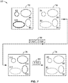
- FIG. 5 through FIG. 7 show a second method 50 of this presentation for performing TRFI without lifetime fitting.
- the decaying intensity is gated and sampled twice while both the fluorophores 64 and 66 are still fluorescing (see FIG. 6 ).
- FIG. 5 and FIG. 6 after the excitation pulse at step 52, two images are obtained.
- the first image 72 is obtained after pulse 68 at step 54, thus having a high fluorescence intensity.
- the second image 74 is then obtained at step 56 a set interval after the first image 72, and thus has a lower intensity than the first image 72.
- the second image 74 is divided by the first image 72, and a new image 76 is generated at step 60 showing the ratio of the two images.
- the ratio value will be the same, no matter what the initial intensity value is.
- the differences are enhanced to generate image 78 by multiplying all pixels with a constant (e.g., 100x in FIG. 7 ) via the image processing software.
- the two regions at the left in image 72 represent the area of the shorter-lifetime fluorophore, while those at the right are the distribution of the longer-lifetime fluorophore.
- the methods 10 and 50 shown in FIG. 2 through FIG. 7 are shown with respect to imaging two fluorophores. However, it is appreciated that the methods 10 and 50 may also be used for samples composed of more than two fluorophores by using multiple subtractions. For simplicity, the two-fluorophore sample is merely used as an example.
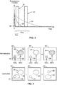
- FIG. 8 shows an exemplary system 100 for implementation of TRFI methods 10, 50 without lifetime fitting in accordance with this presentation.
- System 100 comprises a light source 102 configured for generating an excitation pulse (e.g. pulse 38 in FIG. 3 and pulse 68 in FIG. 6 ) that is structured to generate a specific illumination profile to excite the fluorophores of the desired target medium (e.g. tissue).
- the light source 102 comprises an LED.
- the light source 102 is coupled to a delay generator 108 and computer 104.
- Computer 104 is coupled to CCD array 112 for receiving signals from the excited medium or sample 120, and a processor configured to execute application software 106.
- Application software 106 comprises algorithms/programming configured to shape the pulse from light source 102, as well as perform the operations of methods 10 and/or 50 for evaluating the images obtained from the excited medium to perform TRFI.
- the light source 102 generates excitation pulses into target sample 120 via a series of filters/lenses 118 and mirrors 116 (e.g. dichromatic mirror, etc.).
- the fluorescence signal from the excited sample 120 is detected from CCD array 112.
- the fluorescence signal is gated, intensified, and recorded by an iCCD camera, which functions as a combination of a gated optical image intensifier 110 and a CCD camera 112. Data from the CCD is then transferred to the computer 104 for image processing and monitor 114 for display.
- FIG. 9A through FIG. 11C the methods 10, 50 of this presentation were tested using Fluorescein and Rhodamine-B as sample components of a target medium.
- the lifetime of Fluorescein is around 4.0 ns in the solvent of phosphate buffer pH 7.5, while the lifetime of Rhodamine-B is around 1.68 ns in water.
- the lifetime value may change with various factors, such as solvent and concentration.
- the two materials were placed side by side and were first imaged using subtraction method 10 in accordance with this presentation.
- the data shows successful detection of one fluorophore from the other by normalizing and subtracting the two sampled images.
- FIG. 9A and FIG. 9B show two sampled images, with FIG.
- FIG. 9A being the image taken when both fluorophores were still fluorescing
- FIG. 9B being the image taken when Rhodamine-B decays to zero and only Fluorescein was still fluorescing
- FIG. 9C is the image after normalization, subtraction and intensification of FIGS. 9A and 9B .
- Method 50 was also tested with the same set of samples. Two fluorescence images were recorded while both fluorophores were still fluorescing. The images sampled at 26ns and 40ns after the excitation are shown in FIG. 10A and FIG. 10B , respectively. Dividing image of FIG. 10B by the image of FIG. 10A , and multiplying by a constant, we obtained the image of FIG. 10C . The data point of FIG. 10C represents the multiplication of the ratio of FIG. 10A and FIG. 10B .
- FIG. 11A through 11C An optical density was used to partially cover the sample. Therefore, the intensity of fluorescence signal will be non-uniform at each side on the sampled images, shown in FIG. 11A and FIG. 11B . However, by using method 50 of this presentation, we obtained an image in FIG. 11C that clearly distinguishes Fluorescein and Rhodamine-B, without the effect of the nonuniformity of the fluorescence intensity.
- FIG. 12 illustrates a circuit diagram of an exemplary pulse-shaping light source 102 in accordance with this presentation.
- the illumination source or circuit 102 comprises a light emitting element 130 that is coupled to a pulse generator 134 via transmission line 140, 142, and is configured to produce a specific illumination intensity profile (i.e. pulse shaping) that is optimal for the methods 10, 50 of this presentation, as well as existing TRFI systems.
- the circuit 102 optimally comprises a stub line 136, LED (light-emitting diode)-based light emitting element 130, and a resistive element 132.
- the stub line 136 functions as a delay-line, negative loop-back and is connected to the terminals 140, 142 of the illumination circuit 102.
- the final optical impulse is formed by combining the pulse reflected from the short-circuited stub 136 and that transmitted across the junction between the short-circuited stub 136 and the transmission line 140,142.
- a linearly decaying illumination profile of the illumination source, and in particular an illumination source 102 comprising an LED 130, can be achieved by using the above pulse-shaping configuration.
- a linear decay pulse is advantageous, since the pulse's decay slope is well defined and is finite. This makes de-convolving of optical pulses an easier task compared to non-linear decay profiles.
- pulses are structured with a cycle time longer than the pulse width.
- the circuit is optimally configured with a stub line 136 as shown in FIG. 12 .
- any element that is capable of shaping the pulse can be used using the following concept.
- the LED 130 illumination characteristic is governed by the recombination of electron hole pairs in the depletion region of the LED's p-n junction. With a given square pulse, the decay in intensity of the LED is described by the recombination time coefficient; an exponential decay function.
- a controlled linear illumination decay profile (or other shapes) can be achieved by the stub line 136, for example, acting as a passive delay line, depleting charge in the circuit and the p-n junction. Controlling the characteristics of the stub line 136 (e.g. shape, length, and material) and/or the pulse, a linear decay illumination profile can be achieved.
- Illumination circuit 102 may be used to drive LEDs as the light-emitting element 130, as well as other illuminating devices such as semiconductor lasers and other semiconductor light sources that exhibit a nonlinear luminosity decay profile.
- LEDs as the light-emitting element 130
- other illuminating devices such as semiconductor lasers and other semiconductor light sources that exhibit a nonlinear luminosity decay profile.
- a finite optical pulse with a well-defined linearly decaying slope is difficult to achieve in such systems.
- the auxiliary pulse generator 134 is capable of driving the illumination circuit 102 with adjustable pulse parameters, e.g. pulse length, amplitude and repetition rate are adjustable.
- the pulse widths generated from the circuit 102 are generally in the range of 0.5 nanoseconds (ns) or greater, and preferably in the range of 1 ns to 20 ns, and more preferably approximately 10 ns.
- This pulse width range is significantly longer than the typical laser-pulsed system for fluorescence lifetime measurements (which are generally in the picosecond range), and allows for much less expensive light sources such as LED's. It is appreciated that this range may vary according to the evaluated medium (e.g.
- tissue type and other factors/parameters such as duty cycle, power, etc.
- the shorter the pulse the longer it takes to image. Accordingly, existing pulsed laser systems often take a minute or longer, while the methods 10, 50 of this presentation contrast the medium in less than a second, even while using less "sophisticated" illumination sources such as LED's.
- FLIM fluorescence lifetime imaging microscopy
- measurements of fluorescence lifetime using the pulsed LED circuit 102 of this presentation provide an economical alternative to existing pulsed-laser systems.
- Using the pulsed LED circuit 102 of this presentation in FLIM achieves superior analysis by simplifying the pulse analysis to give better measurements, and overcomes the deconvolution errors when fluorescent lifetimes are calculated.
- the linear luminosity decay profile generated from the pulsed LED circuit 102 of this presentation achieves better contrast in raw images, simplifies analysis, and reduces the computational power needed for image processing.
- FIG. 13 is a plot showing two excitation pulses: a first exponential pulse (10ns decay coefficient), and a second linear pulse (slope - 10ns), along with 2 samples having a 2ns and 2.5ns exponential decay coefficient, respectively. All signals were normalized to eliminate amplitude variation and emphasize changes only due to lifetime's differences.
- FIG. 14 shows the convolution product of each excitation pulse with the two samples, thus creating four decay curves, which simulates the actual measured signals of the FLIM system.
- FIG. 15 shows a plot of two samples after normalization according to method 50 of this presentation for excitation pulses having both linear and exponential decay.
- FIG. 15 illustrates the result of dividing the points of the decay by the initial (highest) intensity, to get ratios of fluorescence for each point in time to the initial intensity. Four ratios are shown in the plot, wherein each point in the plot is a division product, with the highest intensity being 1, creating a normalized picture, due only to lifetime differences. This aids in eliminating differences in amplitude, and shows only the lifetime characteristics of each signal.
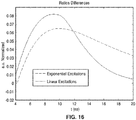
- FIG. 16 shows a plot of subtraction of two signals from the same excitation source according to method 10 of this presentation for excitation pulses having both linear and exponential decay.
- FIG. 16 shows the ratios of the differences between each of the excitation sources, resulting in two graphs. Each graph is the result of subtraction of the two ratios with the same excitation function (e.g. linear vs. exponential). A larger discrepancy is preferred, since it will produce a sharper contrast image.
- the differences of the linearly excited pulses (solid line) generated from the light source 102 are clearly larger than the exponentially excited pulses (dashed line) within the high signal-to-noise regime (4ns-12ns).
- the exponential decay pulse cannot overcome the linear decay pulse generated from the system of this presentation at any time. This shows the advantage in using linearly-modulated excitation pulse of this presentation over exponential pulse in the FLIM system.
- the methods of this presentation are capable of obtaining time-resolved fluorescence images without the need of extracting the fluorescence lifetime. No extra adjustment on the TRFI system 100 is required.
- the pulse-shaping light source of this presentation may be particularly beneficial in practicing the methods of this presentation. Comparing to the conventional TRFI, the systems and methods of this presentation are reliable, simple, straight-forward and time-saving.
- the systems and methods of this presentation are particularly adapted for imaging in biomedical applications.
- Such applications may include, but are not limited to: (1) cancer detection for a broad range of imaging procedures, both endoscopic and microscopic, (2) cosmetic application for determination of collagen and elastin ratio, and (3) identification of unknown substances in medical forensics.
- the systems and methods of this presentation may be used in any application where time-resolved fluorescence is contemplated, particularly in applications where obtaining contrast within the medium is an objective.
- Such uses may comprise non-biomedical applications, such as spectroscopy for combustion, vapors, etc.
- the CCD 112 may be coupled to a variety of objectives such as for a telescope, microscope, single lens reflex (SLR) camera, or the like for a number of difference applications.
- the systems and methods of this presentation provide a faster, simpler, and more reliable way to obtain time-resolved fluorescence images. Fitting the decay curve to extract the fluorescence lifetime is difficult, time-consuming, and not reliable.
- the methods of this presentation provide rapid determination of the relative lifetime within an image, instead of extracting the value of the fluorescence lifetime. This is similar to X-ray imaging in which all points in the images are viewed relatively to their ability to absorb or transmit X-ray.
- Embodiments of this presentation may be described with reference to flowchart illustrations of methods and systems according to embodiments of this presentation, and/or algorithms, formulae, or other computational depictions, which may also be implemented as computer program products.
- each block or step of a flowchart, and combinations of blocks (and/or steps) in a flowchart, algorithm, formula, or computational depiction can be implemented by various means, such as hardware, firmware, and/or software including one or more computer program instructions embodied in computer-readable program code logic.
- any such computer program instructions may be loaded onto a computer, including without limitation a general purpose computer or special purpose computer, or other programmable processing apparatus to produce a machine, such that the computer program instructions which execute on the computer or other programmable processing apparatus create means for implementing the functions specified in the block(s) of the flowchart(s).
- blocks of the flowcharts, algorithms, formulae, or computational depictions support combinations of means for performing the specified functions, combinations of steps for performing the specified functions, and computer program instructions, such as embodied in computer-readable program code logic means, for performing the specified functions. It will also be understood that each block of the flowchart illustrations, algorithms, formulae, or computational depictions and combinations thereof described herein, can be implemented by special purpose hardware-based computer systems which perform the specified functions or steps, or combinations of special purpose hardware and computer-readable program code logic means.
- these computer program instructions may also be stored in a computer-readable memory that can direct a computer or other programmable processing apparatus to function in a particular manner, such that the instructions stored in the computer-readable memory produce an article of manufacture including instruction means which implement the function specified in the block(s) of the flowchart(s).
- the computer program instructions may also be loaded onto a computer or other programmable processing apparatus to cause a series of operational steps to be performed on the computer or other programmable processing apparatus to produce a computer-implemented process such that the instructions which execute on the computer or other programmable processing apparatus provide steps for implementing the functions specified in the block(s) of the flowchart(s), algorithm(s), formula(e), or computational depiction(s).
Landscapes
- Health & Medical Sciences (AREA)
- Physics & Mathematics (AREA)
- Chemical & Material Sciences (AREA)
- Analytical Chemistry (AREA)
- General Physics & Mathematics (AREA)
- Immunology (AREA)
- Life Sciences & Earth Sciences (AREA)
- Biochemistry (AREA)
- Pathology (AREA)
- General Health & Medical Sciences (AREA)
- Nuclear Medicine, Radiotherapy & Molecular Imaging (AREA)
- Optics & Photonics (AREA)
- Chemical Kinetics & Catalysis (AREA)
- Molecular Biology (AREA)
- Biomedical Technology (AREA)
- Engineering & Computer Science (AREA)
- Investigating, Analyzing Materials By Fluorescence Or Luminescence (AREA)
Applications Claiming Priority (2)
| Application Number | Priority Date | Filing Date | Title |
|---|---|---|---|
| US201261605844P | 2012-03-02 | 2012-03-02 | |
| PCT/US2013/028758 WO2013131062A1 (en) | 2012-03-02 | 2013-03-01 | System and method for time-resolved fluorescence imaging and pulse shaping |
Publications (3)
| Publication Number | Publication Date |
|---|---|
| EP2820398A1 EP2820398A1 (en) | 2015-01-07 |
| EP2820398A4 EP2820398A4 (en) | 2016-01-20 |
| EP2820398B1 true EP2820398B1 (en) | 2018-10-24 |
Family
ID=49083367
Family Applications (1)
| Application Number | Title | Priority Date | Filing Date |
|---|---|---|---|
| EP13755562.9A Active EP2820398B1 (en) | 2012-03-02 | 2013-03-01 | Apparatus for time-resolved fluorescence imaging and pulse shaping |
Country Status (6)
| Country | Link |
|---|---|
| US (1) | US10041883B2 (es) |
| EP (1) | EP2820398B1 (es) |
| JP (1) | JP6389763B2 (es) |
| AU (1) | AU2013225655A1 (es) |
| CA (1) | CA2865948A1 (es) |
| WO (1) | WO2013131062A1 (es) |
Families Citing this family (15)
| Publication number | Priority date | Publication date | Assignee | Title |
|---|---|---|---|---|
| CA2865948A1 (en) | 2012-03-02 | 2013-09-06 | Warren S. Grundfest | System and method for time-resolved fluorescence imaging and pulse shaping |
| WO2014168734A1 (en) | 2013-03-15 | 2014-10-16 | Cedars-Sinai Medical Center | Time-resolved laser-induced fluorescence spectroscopy systems and uses thereof |
| FR3013452B1 (fr) * | 2013-11-21 | 2016-02-05 | Centre Nat Rech Scient | Procede de detection d'une espece fluorescente reversiblement photoconvertible |
| JP6542044B2 (ja) | 2015-06-30 | 2019-07-10 | オリンパス株式会社 | 顕微鏡システム |
| JP7266519B2 (ja) | 2016-04-01 | 2023-04-28 | ブラック ライト サージカル, インコーポレイテッド | 時間分解蛍光分光法のためのシステム、デバイス、および方法 |
| US20210334513A1 (en) * | 2016-08-03 | 2021-10-28 | Royal Melbourne Institute Of Technology | A method for distinguishing between more than one fluorescent species present in a sample |
| EP3523054A4 (en) | 2016-10-04 | 2020-06-03 | The Regents of The University of California | MULTI-FREQUENCY HARMONIC ACOUSTOGRAPHY FOR TARGET IDENTIFICATION AND BOUNDARY DETECTION |
| KR101859172B1 (ko) * | 2016-12-22 | 2018-05-16 | (주) 인텍플러스 | 아날로그 평균지연 방법에서 수집한 신호로부터 가상의 형광분포 모델을 통해 최소자승오차를 계산하여 2개 이상의 형광수명 성분을 구하는 형광수명 측정장치 및 그 측정방법 |
| JP7221285B2 (ja) * | 2017-11-01 | 2023-02-13 | ザ リージェンツ オブ ザ ユニバーシティ オブ カリフォルニア | 切除縁を術中に評価するための画像化方法およびシステム |
| KR102126694B1 (ko) | 2018-06-01 | 2020-06-25 | 주식회사 수젠텍 | 시간분해 형광신호 분석장치 |
| JP2020071152A (ja) * | 2018-10-31 | 2020-05-07 | ソニー株式会社 | 免疫染色方法、免疫染色システム、および免疫染色キット |
| US11933959B2 (en) | 2019-02-01 | 2024-03-19 | Thorlabs, Inc. | High dynamic range imaging |
| WO2021076972A1 (en) | 2019-10-17 | 2021-04-22 | C2Sense, Inc. | Luminescence imaging for sensing |
| CN114729890A (zh) * | 2019-10-17 | 2022-07-08 | C2感官有限公司 | 用于感测和/或认证的发光成像 |
| US20220120683A1 (en) * | 2020-10-15 | 2022-04-21 | Visera Technologies Company Limited | Bio-chip, bio-detection system and bio-detection method |
Citations (2)
| Publication number | Priority date | Publication date | Assignee | Title |
|---|---|---|---|---|
| US20010011930A1 (en) * | 1999-02-05 | 2001-08-09 | Mark Kintis | Nonlinear transmission line waveform generator |
| EP1686685A2 (en) * | 2005-01-19 | 2006-08-02 | Northrop Grumman Corporation | Tunable, maximum power output, frequency harmonic comb generator |
Family Cites Families (20)
| Publication number | Priority date | Publication date | Assignee | Title |
|---|---|---|---|---|
| US4791310A (en) * | 1986-10-02 | 1988-12-13 | Syracuse University | Fluorescence microscopy |
| US4785495A (en) | 1987-08-17 | 1988-11-22 | Dellis Edward A | Moldable hand grips |
| JP2977746B2 (ja) * | 1995-08-23 | 1999-11-15 | 旭テクノグラス株式会社 | 蛍光ガラス線量計測定方法及びその測定装置 |
| US6272376B1 (en) * | 1999-01-22 | 2001-08-07 | Cedars-Sinai Medical Center | Time-resolved, laser-induced fluorescence for the characterization of organic material |
| EP1659944A4 (en) | 2003-08-19 | 2008-10-29 | Cedars Sinai Medical Center | METHODS FOR FLUORESCENCE LIFETIME PRESENTATION MICROSCOPY AND SPECTROSCOPY |
| JP2005269051A (ja) * | 2004-03-17 | 2005-09-29 | Sysmex Corp | 発光ダイオードの駆動回路 |
| JP2008517280A (ja) * | 2004-10-18 | 2008-05-22 | マクオーリー ユニヴァーシティ | 蛍光検出 |
| JP2006226848A (ja) * | 2005-02-17 | 2006-08-31 | Olympus Corp | 蛍光撮像装置 |
| WO2006127967A2 (en) * | 2005-05-25 | 2006-11-30 | Massachusetts Institute Of Technology | Multifocal scanning microscopy systems and methods |
| US7648239B2 (en) | 2007-05-01 | 2010-01-19 | Richard Spaide | Autofluorescence photography using a fundus camera |
| JP4538033B2 (ja) * | 2007-09-10 | 2010-09-08 | 株式会社沖データ | 駆動回路、ledヘッドおよび画像形成装置 |
| JP2010071982A (ja) * | 2008-08-20 | 2010-04-02 | Japan Atomic Energy Agency | レーザー誘起蛍光強度の減衰率比較によるアスベスト識別法 |
| GB0905690D0 (en) | 2009-04-01 | 2009-05-20 | Univ Cardiff | Fluorescence detection schemes |
| JP5437864B2 (ja) * | 2010-03-10 | 2014-03-12 | 富士フイルム株式会社 | pH測定装置の作動方法、検出装置の作動方法、及び生体物質分析装置の作動方法、並びに各装置 |
| JP2011185842A (ja) * | 2010-03-10 | 2011-09-22 | Fujifilm Corp | 光誘起自家蛍光の時間分解測定による生物試料の低酸素領域分析方法とその装置 |
| JP5626760B2 (ja) * | 2010-03-31 | 2014-11-19 | ソニー株式会社 | 蛍光像取得方法、蛍光像取得プログラム及び蛍光像取得装置 |
| GB201007055D0 (en) * | 2010-04-28 | 2010-06-09 | Vib Vzw | Method and apparatus for the imaging of a labelled sample |
| KR20140116353A (ko) | 2010-10-25 | 2014-10-02 | 스티븐 버두너 | 알츠하이머 병, 외상성 뇌손상, 시력감퇴, 신경병 및 안질환의 진단과 예측을 위해 망막내 아밀로이드를 감지하는 장치와 방법 |
| US10222335B2 (en) | 2010-10-27 | 2019-03-05 | The Regents Of The University Of California | Phasor method to fluorescence lifetime microscopy to discriminate metabolic state of cells in living tissue |
| CA2865948A1 (en) | 2012-03-02 | 2013-09-06 | Warren S. Grundfest | System and method for time-resolved fluorescence imaging and pulse shaping |
-
2013
- 2013-03-01 CA CA2865948A patent/CA2865948A1/en not_active Abandoned
- 2013-03-01 JP JP2014560114A patent/JP6389763B2/ja active Active
- 2013-03-01 AU AU2013225655A patent/AU2013225655A1/en not_active Abandoned
- 2013-03-01 EP EP13755562.9A patent/EP2820398B1/en active Active
- 2013-03-01 WO PCT/US2013/028758 patent/WO2013131062A1/en active Application Filing
-
2014
- 2014-08-29 US US14/472,735 patent/US10041883B2/en active Active
Patent Citations (2)
| Publication number | Priority date | Publication date | Assignee | Title |
|---|---|---|---|---|
| US20010011930A1 (en) * | 1999-02-05 | 2001-08-09 | Mark Kintis | Nonlinear transmission line waveform generator |
| EP1686685A2 (en) * | 2005-01-19 | 2006-08-02 | Northrop Grumman Corporation | Tunable, maximum power output, frequency harmonic comb generator |
Non-Patent Citations (1)
| Title |
|---|
| ASAEL PAPOUR: "Analysis and Optimization of a Lifetime Fluorescence System to Detect Structural Protein Signatures in Varying Host Mediums for Rapid Biomedical Imaging", 1 January 2012 (2012-01-01), pages 1 - 66, XP055424816, Retrieved from the Internet <URL:https://escholarship.org/content/qt4hj006tj/qt4hj006tj.pdf> [retrieved on 20171114] * |
Also Published As
| Publication number | Publication date |
|---|---|
| AU2013225655A1 (en) | 2014-09-18 |
| EP2820398A1 (en) | 2015-01-07 |
| JP6389763B2 (ja) | 2018-09-12 |
| US10041883B2 (en) | 2018-08-07 |
| JP2015508905A (ja) | 2015-03-23 |
| US20150053871A1 (en) | 2015-02-26 |
| EP2820398A4 (en) | 2016-01-20 |
| WO2013131062A1 (en) | 2013-09-06 |
| CA2865948A1 (en) | 2013-09-06 |
Similar Documents
| Publication | Publication Date | Title |
|---|---|---|
| EP2820398B1 (en) | Apparatus for time-resolved fluorescence imaging and pulse shaping | |
| US9784678B2 (en) | Method for improving fluorescence image contrast | |
| Chen et al. | Monte Carlo based method for fluorescence tomographic imaging with lifetime multiplexing using time gates | |
| US8357915B2 (en) | Method and device for measuring optical characteristics of an object | |
| US20090164130A1 (en) | Fluorescence-lifetime-based tomography | |
| JP6637605B2 (ja) | 電子励起状態の平均寿命時間を測定するための発光寿命時間測定方法及び装置 | |
| Clegg et al. | Fluorescence lifetime-resolved imaging microscopy: a general description of lifetime-resolved imaging measurements | |
| Chang et al. | Enhancing precision in time-domain fluorescence lifetime imaging | |
| Jiang et al. | Quasi-real-time fluorescence imaging with lifetime dependent contrast | |
| US20150377783A1 (en) | System and method for fluorescence detection | |
| Chang et al. | Total variation versus wavelet‐based methods for image denoising in fluorescence lifetime imaging microscopy | |
| US8649010B2 (en) | Integral transformed optical measurement method and apparatus | |
| US11307140B2 (en) | Signal acquisition device | |
| JP6290865B2 (ja) | 励起状態の寿命に関してサンプルを検査する方法及び装置 | |
| JP2012522980A (ja) | 蛍光寿命イメージング | |
| Liu et al. | Lifetime computing algorithms based on exponential pattern retrieve and polynomial fitting in fluorescence lifetime imaging microscopy | |
| JP3579628B2 (ja) | 葉のクロロフィル含量推定方法およびこれを利用した推定装置 | |
| Bednarkiewicz et al. | Global analysis of microscopic fluorescence lifetime images using spectral segmentation and a digital micromirror spatial illuminator | |
| US20220299434A1 (en) | Biological tissue identification method, biological tissue identification device, and biological tissue identification program | |
| JP5171816B2 (ja) | 集積回路を分析する方法、観察方法、及びこれらの関連装置 | |
| US20240265666A1 (en) | Apparatus and method for image acquisition based on enhancement of maximum contrast ratio and storage medium storing instructions to perform method for image acquisition | |
| Zhao et al. | mb-FLIM: model-based fluorescence lifetime imaging | |
| Chen et al. | General concerns of FLIM data representation and analysis | |
| Yuliang | A High Precision Method for Analysis of Fluorescence Lifetime Imaging Microscopy Data Based on Levenberg-Marquardt Technique | |
| JP2008180637A (ja) | 光信号解析方法および光信号解析装置 |
Legal Events
| Date | Code | Title | Description |
|---|---|---|---|
| PUAI | Public reference made under article 153(3) epc to a published international application that has entered the european phase |
Free format text: ORIGINAL CODE: 0009012 |
|
| 17P | Request for examination filed |
Effective date: 20140926 |
|
| AK | Designated contracting states |
Kind code of ref document: A1 Designated state(s): AL AT BE BG CH CY CZ DE DK EE ES FI FR GB GR HR HU IE IS IT LI LT LU LV MC MK MT NL NO PL PT RO RS SE SI SK SM TR |
|
| AX | Request for extension of the european patent |
Extension state: BA ME |
|
| DAX | Request for extension of the european patent (deleted) | ||
| RIC1 | Information provided on ipc code assigned before grant |
Ipc: G02B 21/16 20060101ALI20150917BHEP Ipc: G01N 21/64 20060101AFI20150917BHEP |
|
| RA4 | Supplementary search report drawn up and despatched (corrected) |
Effective date: 20151218 |
|
| RIC1 | Information provided on ipc code assigned before grant |
Ipc: G01N 21/64 20060101AFI20151214BHEP Ipc: G02B 21/16 20060101ALI20151214BHEP |
|
| STAA | Information on the status of an ep patent application or granted ep patent |
Free format text: STATUS: EXAMINATION IS IN PROGRESS |
|
| 17Q | First examination report despatched |
Effective date: 20171120 |
|
| GRAP | Despatch of communication of intention to grant a patent |
Free format text: ORIGINAL CODE: EPIDOSNIGR1 |
|
| STAA | Information on the status of an ep patent application or granted ep patent |
Free format text: STATUS: GRANT OF PATENT IS INTENDED |
|
| INTG | Intention to grant announced |
Effective date: 20180528 |
|
| RIN1 | Information on inventor provided before grant (corrected) |
Inventor name: GRUNDFEST, WARREN S. Inventor name: PAPOUR, ASAEL Inventor name: STAFSUDD, OSCAR M. Inventor name: JIANG, PEI-CHI Inventor name: ST. JOHN, MAIE Inventor name: TAYLOR, ZACHARY DEIS |
|
| GRAS | Grant fee paid |
Free format text: ORIGINAL CODE: EPIDOSNIGR3 |
|
| GRAA | (expected) grant |
Free format text: ORIGINAL CODE: 0009210 |
|
| STAA | Information on the status of an ep patent application or granted ep patent |
Free format text: STATUS: THE PATENT HAS BEEN GRANTED |
|
| REG | Reference to a national code |
Ref country code: FR Ref legal event code: PLFP Year of fee payment: 7 |
|
| AK | Designated contracting states |
Kind code of ref document: B1 Designated state(s): AL AT BE BG CH CY CZ DE DK EE ES FI FR GB GR HR HU IE IS IT LI LT LU LV MC MK MT NL NO PL PT RO RS SE SI SK SM TR |
|
| REG | Reference to a national code |
Ref country code: CH Ref legal event code: EP |
|
| REG | Reference to a national code |
Ref country code: IE Ref legal event code: FG4D |
|
| REG | Reference to a national code |
Ref country code: AT Ref legal event code: REF Ref document number: 1057283 Country of ref document: AT Kind code of ref document: T Effective date: 20181115 |
|
| REG | Reference to a national code |
Ref country code: DE Ref legal event code: R096 Ref document number: 602013045578 Country of ref document: DE |
|
| REG | Reference to a national code |
Ref country code: NL Ref legal event code: MP Effective date: 20181024 |
|
| REG | Reference to a national code |
Ref country code: LT Ref legal event code: MG4D |
|
| REG | Reference to a national code |
Ref country code: AT Ref legal event code: MK05 Ref document number: 1057283 Country of ref document: AT Kind code of ref document: T Effective date: 20181024 |
|
| PG25 | Lapsed in a contracting state [announced via postgrant information from national office to epo] |
Ref country code: NL Free format text: LAPSE BECAUSE OF FAILURE TO SUBMIT A TRANSLATION OF THE DESCRIPTION OR TO PAY THE FEE WITHIN THE PRESCRIBED TIME-LIMIT Effective date: 20181024 |
|
| PG25 | Lapsed in a contracting state [announced via postgrant information from national office to epo] |
Ref country code: IS Free format text: LAPSE BECAUSE OF FAILURE TO SUBMIT A TRANSLATION OF THE DESCRIPTION OR TO PAY THE FEE WITHIN THE PRESCRIBED TIME-LIMIT Effective date: 20190224 Ref country code: NO Free format text: LAPSE BECAUSE OF FAILURE TO SUBMIT A TRANSLATION OF THE DESCRIPTION OR TO PAY THE FEE WITHIN THE PRESCRIBED TIME-LIMIT Effective date: 20190124 Ref country code: LT Free format text: LAPSE BECAUSE OF FAILURE TO SUBMIT A TRANSLATION OF THE DESCRIPTION OR TO PAY THE FEE WITHIN THE PRESCRIBED TIME-LIMIT Effective date: 20181024 Ref country code: BG Free format text: LAPSE BECAUSE OF FAILURE TO SUBMIT A TRANSLATION OF THE DESCRIPTION OR TO PAY THE FEE WITHIN THE PRESCRIBED TIME-LIMIT Effective date: 20190124 Ref country code: ES Free format text: LAPSE BECAUSE OF FAILURE TO SUBMIT A TRANSLATION OF THE DESCRIPTION OR TO PAY THE FEE WITHIN THE PRESCRIBED TIME-LIMIT Effective date: 20181024 Ref country code: LV Free format text: LAPSE BECAUSE OF FAILURE TO SUBMIT A TRANSLATION OF THE DESCRIPTION OR TO PAY THE FEE WITHIN THE PRESCRIBED TIME-LIMIT Effective date: 20181024 Ref country code: PL Free format text: LAPSE BECAUSE OF FAILURE TO SUBMIT A TRANSLATION OF THE DESCRIPTION OR TO PAY THE FEE WITHIN THE PRESCRIBED TIME-LIMIT Effective date: 20181024 Ref country code: AT Free format text: LAPSE BECAUSE OF FAILURE TO SUBMIT A TRANSLATION OF THE DESCRIPTION OR TO PAY THE FEE WITHIN THE PRESCRIBED TIME-LIMIT Effective date: 20181024 Ref country code: HR Free format text: LAPSE BECAUSE OF FAILURE TO SUBMIT A TRANSLATION OF THE DESCRIPTION OR TO PAY THE FEE WITHIN THE PRESCRIBED TIME-LIMIT Effective date: 20181024 Ref country code: FI Free format text: LAPSE BECAUSE OF FAILURE TO SUBMIT A TRANSLATION OF THE DESCRIPTION OR TO PAY THE FEE WITHIN THE PRESCRIBED TIME-LIMIT Effective date: 20181024 |
|
| PG25 | Lapsed in a contracting state [announced via postgrant information from national office to epo] |
Ref country code: PT Free format text: LAPSE BECAUSE OF FAILURE TO SUBMIT A TRANSLATION OF THE DESCRIPTION OR TO PAY THE FEE WITHIN THE PRESCRIBED TIME-LIMIT Effective date: 20190224 Ref country code: SE Free format text: LAPSE BECAUSE OF FAILURE TO SUBMIT A TRANSLATION OF THE DESCRIPTION OR TO PAY THE FEE WITHIN THE PRESCRIBED TIME-LIMIT Effective date: 20181024 Ref country code: AL Free format text: LAPSE BECAUSE OF FAILURE TO SUBMIT A TRANSLATION OF THE DESCRIPTION OR TO PAY THE FEE WITHIN THE PRESCRIBED TIME-LIMIT Effective date: 20181024 Ref country code: GR Free format text: LAPSE BECAUSE OF FAILURE TO SUBMIT A TRANSLATION OF THE DESCRIPTION OR TO PAY THE FEE WITHIN THE PRESCRIBED TIME-LIMIT Effective date: 20190125 Ref country code: RS Free format text: LAPSE BECAUSE OF FAILURE TO SUBMIT A TRANSLATION OF THE DESCRIPTION OR TO PAY THE FEE WITHIN THE PRESCRIBED TIME-LIMIT Effective date: 20181024 |
|
| REG | Reference to a national code |
Ref country code: DE Ref legal event code: R097 Ref document number: 602013045578 Country of ref document: DE |
|
| PG25 | Lapsed in a contracting state [announced via postgrant information from national office to epo] |
Ref country code: IT Free format text: LAPSE BECAUSE OF FAILURE TO SUBMIT A TRANSLATION OF THE DESCRIPTION OR TO PAY THE FEE WITHIN THE PRESCRIBED TIME-LIMIT Effective date: 20181024 Ref country code: DK Free format text: LAPSE BECAUSE OF FAILURE TO SUBMIT A TRANSLATION OF THE DESCRIPTION OR TO PAY THE FEE WITHIN THE PRESCRIBED TIME-LIMIT Effective date: 20181024 Ref country code: CZ Free format text: LAPSE BECAUSE OF FAILURE TO SUBMIT A TRANSLATION OF THE DESCRIPTION OR TO PAY THE FEE WITHIN THE PRESCRIBED TIME-LIMIT Effective date: 20181024 |
|
| PG25 | Lapsed in a contracting state [announced via postgrant information from national office to epo] |
Ref country code: EE Free format text: LAPSE BECAUSE OF FAILURE TO SUBMIT A TRANSLATION OF THE DESCRIPTION OR TO PAY THE FEE WITHIN THE PRESCRIBED TIME-LIMIT Effective date: 20181024 Ref country code: SM Free format text: LAPSE BECAUSE OF FAILURE TO SUBMIT A TRANSLATION OF THE DESCRIPTION OR TO PAY THE FEE WITHIN THE PRESCRIBED TIME-LIMIT Effective date: 20181024 Ref country code: RO Free format text: LAPSE BECAUSE OF FAILURE TO SUBMIT A TRANSLATION OF THE DESCRIPTION OR TO PAY THE FEE WITHIN THE PRESCRIBED TIME-LIMIT Effective date: 20181024 Ref country code: SK Free format text: LAPSE BECAUSE OF FAILURE TO SUBMIT A TRANSLATION OF THE DESCRIPTION OR TO PAY THE FEE WITHIN THE PRESCRIBED TIME-LIMIT Effective date: 20181024 |
|
| PLBE | No opposition filed within time limit |
Free format text: ORIGINAL CODE: 0009261 |
|
| STAA | Information on the status of an ep patent application or granted ep patent |
Free format text: STATUS: NO OPPOSITION FILED WITHIN TIME LIMIT |
|
| 26N | No opposition filed |
Effective date: 20190725 |
|
| PG25 | Lapsed in a contracting state [announced via postgrant information from national office to epo] |
Ref country code: SI Free format text: LAPSE BECAUSE OF FAILURE TO SUBMIT A TRANSLATION OF THE DESCRIPTION OR TO PAY THE FEE WITHIN THE PRESCRIBED TIME-LIMIT Effective date: 20181024 Ref country code: MC Free format text: LAPSE BECAUSE OF FAILURE TO SUBMIT A TRANSLATION OF THE DESCRIPTION OR TO PAY THE FEE WITHIN THE PRESCRIBED TIME-LIMIT Effective date: 20181024 |
|
| REG | Reference to a national code |
Ref country code: CH Ref legal event code: PL |
|
| PG25 | Lapsed in a contracting state [announced via postgrant information from national office to epo] |
Ref country code: LU Free format text: LAPSE BECAUSE OF NON-PAYMENT OF DUE FEES Effective date: 20190301 |
|
| REG | Reference to a national code |
Ref country code: BE Ref legal event code: MM Effective date: 20190331 |
|
| PG25 | Lapsed in a contracting state [announced via postgrant information from national office to epo] |
Ref country code: LI Free format text: LAPSE BECAUSE OF NON-PAYMENT OF DUE FEES Effective date: 20190331 Ref country code: IE Free format text: LAPSE BECAUSE OF NON-PAYMENT OF DUE FEES Effective date: 20190301 Ref country code: CH Free format text: LAPSE BECAUSE OF NON-PAYMENT OF DUE FEES Effective date: 20190331 |
|
| PG25 | Lapsed in a contracting state [announced via postgrant information from national office to epo] |
Ref country code: BE Free format text: LAPSE BECAUSE OF NON-PAYMENT OF DUE FEES Effective date: 20190331 |
|
| PG25 | Lapsed in a contracting state [announced via postgrant information from national office to epo] |
Ref country code: TR Free format text: LAPSE BECAUSE OF FAILURE TO SUBMIT A TRANSLATION OF THE DESCRIPTION OR TO PAY THE FEE WITHIN THE PRESCRIBED TIME-LIMIT Effective date: 20181024 |
|
| PG25 | Lapsed in a contracting state [announced via postgrant information from national office to epo] |
Ref country code: MT Free format text: LAPSE BECAUSE OF NON-PAYMENT OF DUE FEES Effective date: 20190301 |
|
| PG25 | Lapsed in a contracting state [announced via postgrant information from national office to epo] |
Ref country code: CY Free format text: LAPSE BECAUSE OF FAILURE TO SUBMIT A TRANSLATION OF THE DESCRIPTION OR TO PAY THE FEE WITHIN THE PRESCRIBED TIME-LIMIT Effective date: 20181024 |
|
| PG25 | Lapsed in a contracting state [announced via postgrant information from national office to epo] |
Ref country code: HU Free format text: LAPSE BECAUSE OF FAILURE TO SUBMIT A TRANSLATION OF THE DESCRIPTION OR TO PAY THE FEE WITHIN THE PRESCRIBED TIME-LIMIT; INVALID AB INITIO Effective date: 20130301 |
|
| PG25 | Lapsed in a contracting state [announced via postgrant information from national office to epo] |
Ref country code: MK Free format text: LAPSE BECAUSE OF FAILURE TO SUBMIT A TRANSLATION OF THE DESCRIPTION OR TO PAY THE FEE WITHIN THE PRESCRIBED TIME-LIMIT Effective date: 20181024 |
|
| PGFP | Annual fee paid to national office [announced via postgrant information from national office to epo] |
Ref country code: DE Payment date: 20240327 Year of fee payment: 12 Ref country code: GB Payment date: 20240327 Year of fee payment: 12 |
|
| PGFP | Annual fee paid to national office [announced via postgrant information from national office to epo] |
Ref country code: FR Payment date: 20240325 Year of fee payment: 12 |