EP2820172B1 - Elektrolytische wassertrennung unter verwendung eines kohleunterstützten mnox-verbundstoffes - Google Patents
Elektrolytische wassertrennung unter verwendung eines kohleunterstützten mnox-verbundstoffes Download PDFInfo
- Publication number
- EP2820172B1 EP2820172B1 EP13706277.4A EP13706277A EP2820172B1 EP 2820172 B1 EP2820172 B1 EP 2820172B1 EP 13706277 A EP13706277 A EP 13706277A EP 2820172 B1 EP2820172 B1 EP 2820172B1
- Authority
- EP
- European Patent Office
- Prior art keywords
- mno
- mwcnt
- carbon
- composite
- manganese oxide
- Prior art date
- Legal status (The legal status is an assumption and is not a legal conclusion. Google has not performed a legal analysis and makes no representation as to the accuracy of the status listed.)
- Not-in-force
Links
Images








Classifications
-
- B—PERFORMING OPERATIONS; TRANSPORTING
- B82—NANOTECHNOLOGY
- B82Y—SPECIFIC USES OR APPLICATIONS OF NANOSTRUCTURES; MEASUREMENT OR ANALYSIS OF NANOSTRUCTURES; MANUFACTURE OR TREATMENT OF NANOSTRUCTURES
- B82Y30/00—Nanotechnology for materials or surface science, e.g. nanocomposites
-
- C—CHEMISTRY; METALLURGY
- C25—ELECTROLYTIC OR ELECTROPHORETIC PROCESSES; APPARATUS THEREFOR
- C25B—ELECTROLYTIC OR ELECTROPHORETIC PROCESSES FOR THE PRODUCTION OF COMPOUNDS OR NON-METALS; APPARATUS THEREFOR
- C25B1/00—Electrolytic production of inorganic compounds or non-metals
- C25B1/01—Products
- C25B1/02—Hydrogen or oxygen
- C25B1/04—Hydrogen or oxygen by electrolysis of water
-
- C—CHEMISTRY; METALLURGY
- C25—ELECTROLYTIC OR ELECTROPHORETIC PROCESSES; APPARATUS THEREFOR
- C25B—ELECTROLYTIC OR ELECTROPHORETIC PROCESSES FOR THE PRODUCTION OF COMPOUNDS OR NON-METALS; APPARATUS THEREFOR
- C25B11/00—Electrodes; Manufacture thereof not otherwise provided for
- C25B11/04—Electrodes; Manufacture thereof not otherwise provided for characterised by the material
- C25B11/042—Electrodes formed of a single material
- C25B11/043—Carbon, e.g. diamond or graphene
- C25B11/044—Impregnation of carbon
-
- C—CHEMISTRY; METALLURGY
- C25—ELECTROLYTIC OR ELECTROPHORETIC PROCESSES; APPARATUS THEREFOR
- C25B—ELECTROLYTIC OR ELECTROPHORETIC PROCESSES FOR THE PRODUCTION OF COMPOUNDS OR NON-METALS; APPARATUS THEREFOR
- C25B11/00—Electrodes; Manufacture thereof not otherwise provided for
- C25B11/04—Electrodes; Manufacture thereof not otherwise provided for characterised by the material
- C25B11/051—Electrodes formed of electrocatalysts on a substrate or carrier
-
- C—CHEMISTRY; METALLURGY
- C25—ELECTROLYTIC OR ELECTROPHORETIC PROCESSES; APPARATUS THEREFOR
- C25B—ELECTROLYTIC OR ELECTROPHORETIC PROCESSES FOR THE PRODUCTION OF COMPOUNDS OR NON-METALS; APPARATUS THEREFOR
- C25B11/00—Electrodes; Manufacture thereof not otherwise provided for
- C25B11/04—Electrodes; Manufacture thereof not otherwise provided for characterised by the material
- C25B11/051—Electrodes formed of electrocatalysts on a substrate or carrier
- C25B11/054—Electrodes comprising electrocatalysts supported on a carrier
-
- C—CHEMISTRY; METALLURGY
- C25—ELECTROLYTIC OR ELECTROPHORETIC PROCESSES; APPARATUS THEREFOR
- C25B—ELECTROLYTIC OR ELECTROPHORETIC PROCESSES FOR THE PRODUCTION OF COMPOUNDS OR NON-METALS; APPARATUS THEREFOR
- C25B11/00—Electrodes; Manufacture thereof not otherwise provided for
- C25B11/04—Electrodes; Manufacture thereof not otherwise provided for characterised by the material
- C25B11/051—Electrodes formed of electrocatalysts on a substrate or carrier
- C25B11/055—Electrodes formed of electrocatalysts on a substrate or carrier characterised by the substrate or carrier material
-
- C—CHEMISTRY; METALLURGY
- C25—ELECTROLYTIC OR ELECTROPHORETIC PROCESSES; APPARATUS THEREFOR
- C25B—ELECTROLYTIC OR ELECTROPHORETIC PROCESSES FOR THE PRODUCTION OF COMPOUNDS OR NON-METALS; APPARATUS THEREFOR
- C25B11/00—Electrodes; Manufacture thereof not otherwise provided for
- C25B11/04—Electrodes; Manufacture thereof not otherwise provided for characterised by the material
- C25B11/051—Electrodes formed of electrocatalysts on a substrate or carrier
- C25B11/055—Electrodes formed of electrocatalysts on a substrate or carrier characterised by the substrate or carrier material
- C25B11/057—Electrodes formed of electrocatalysts on a substrate or carrier characterised by the substrate or carrier material consisting of a single element or compound
-
- C—CHEMISTRY; METALLURGY
- C25—ELECTROLYTIC OR ELECTROPHORETIC PROCESSES; APPARATUS THEREFOR
- C25B—ELECTROLYTIC OR ELECTROPHORETIC PROCESSES FOR THE PRODUCTION OF COMPOUNDS OR NON-METALS; APPARATUS THEREFOR
- C25B11/00—Electrodes; Manufacture thereof not otherwise provided for
- C25B11/04—Electrodes; Manufacture thereof not otherwise provided for characterised by the material
- C25B11/051—Electrodes formed of electrocatalysts on a substrate or carrier
- C25B11/055—Electrodes formed of electrocatalysts on a substrate or carrier characterised by the substrate or carrier material
- C25B11/057—Electrodes formed of electrocatalysts on a substrate or carrier characterised by the substrate or carrier material consisting of a single element or compound
- C25B11/065—Carbon
-
- C—CHEMISTRY; METALLURGY
- C25—ELECTROLYTIC OR ELECTROPHORETIC PROCESSES; APPARATUS THEREFOR
- C25B—ELECTROLYTIC OR ELECTROPHORETIC PROCESSES FOR THE PRODUCTION OF COMPOUNDS OR NON-METALS; APPARATUS THEREFOR
- C25B11/00—Electrodes; Manufacture thereof not otherwise provided for
- C25B11/04—Electrodes; Manufacture thereof not otherwise provided for characterised by the material
- C25B11/051—Electrodes formed of electrocatalysts on a substrate or carrier
- C25B11/073—Electrodes formed of electrocatalysts on a substrate or carrier characterised by the electrocatalyst material
- C25B11/075—Electrodes formed of electrocatalysts on a substrate or carrier characterised by the electrocatalyst material consisting of a single catalytic element or catalytic compound
-
- C—CHEMISTRY; METALLURGY
- C25—ELECTROLYTIC OR ELECTROPHORETIC PROCESSES; APPARATUS THEREFOR
- C25B—ELECTROLYTIC OR ELECTROPHORETIC PROCESSES FOR THE PRODUCTION OF COMPOUNDS OR NON-METALS; APPARATUS THEREFOR
- C25B11/00—Electrodes; Manufacture thereof not otherwise provided for
- C25B11/04—Electrodes; Manufacture thereof not otherwise provided for characterised by the material
- C25B11/051—Electrodes formed of electrocatalysts on a substrate or carrier
- C25B11/073—Electrodes formed of electrocatalysts on a substrate or carrier characterised by the electrocatalyst material
- C25B11/075—Electrodes formed of electrocatalysts on a substrate or carrier characterised by the electrocatalyst material consisting of a single catalytic element or catalytic compound
- C25B11/077—Electrodes formed of electrocatalysts on a substrate or carrier characterised by the electrocatalyst material consisting of a single catalytic element or catalytic compound the compound being a non-noble metal oxide
-
- H—ELECTRICITY
- H01—ELECTRIC ELEMENTS
- H01M—PROCESSES OR MEANS, e.g. BATTERIES, FOR THE DIRECT CONVERSION OF CHEMICAL ENERGY INTO ELECTRICAL ENERGY
- H01M4/00—Electrodes
- H01M4/86—Inert electrodes with catalytic activity, e.g. for fuel cells
- H01M4/88—Processes of manufacture
- H01M4/8825—Methods for deposition of the catalytic active composition
- H01M4/8842—Coating using a catalyst salt precursor in solution followed by evaporation and reduction of the precursor
-
- H—ELECTRICITY
- H01—ELECTRIC ELEMENTS
- H01M—PROCESSES OR MEANS, e.g. BATTERIES, FOR THE DIRECT CONVERSION OF CHEMICAL ENERGY INTO ELECTRICAL ENERGY
- H01M4/00—Electrodes
- H01M4/86—Inert electrodes with catalytic activity, e.g. for fuel cells
- H01M4/88—Processes of manufacture
- H01M4/8825—Methods for deposition of the catalytic active composition
- H01M4/8846—Impregnation
-
- H—ELECTRICITY
- H01—ELECTRIC ELEMENTS
- H01M—PROCESSES OR MEANS, e.g. BATTERIES, FOR THE DIRECT CONVERSION OF CHEMICAL ENERGY INTO ELECTRICAL ENERGY
- H01M4/00—Electrodes
- H01M4/86—Inert electrodes with catalytic activity, e.g. for fuel cells
- H01M4/90—Selection of catalytic material
- H01M4/9016—Oxides, hydroxides or oxygenated metallic salts
-
- H—ELECTRICITY
- H01—ELECTRIC ELEMENTS
- H01M—PROCESSES OR MEANS, e.g. BATTERIES, FOR THE DIRECT CONVERSION OF CHEMICAL ENERGY INTO ELECTRICAL ENERGY
- H01M4/00—Electrodes
- H01M4/86—Inert electrodes with catalytic activity, e.g. for fuel cells
- H01M4/90—Selection of catalytic material
- H01M4/92—Metals of platinum group
- H01M4/925—Metals of platinum group supported on carriers, e.g. powder carriers
- H01M4/926—Metals of platinum group supported on carriers, e.g. powder carriers on carbon or graphite
-
- Y—GENERAL TAGGING OF NEW TECHNOLOGICAL DEVELOPMENTS; GENERAL TAGGING OF CROSS-SECTIONAL TECHNOLOGIES SPANNING OVER SEVERAL SECTIONS OF THE IPC; TECHNICAL SUBJECTS COVERED BY FORMER USPC CROSS-REFERENCE ART COLLECTIONS [XRACs] AND DIGESTS
- Y02—TECHNOLOGIES OR APPLICATIONS FOR MITIGATION OR ADAPTATION AGAINST CLIMATE CHANGE
- Y02E—REDUCTION OF GREENHOUSE GAS [GHG] EMISSIONS, RELATED TO ENERGY GENERATION, TRANSMISSION OR DISTRIBUTION
- Y02E60/00—Enabling technologies; Technologies with a potential or indirect contribution to GHG emissions mitigation
- Y02E60/30—Hydrogen technology
- Y02E60/36—Hydrogen production from non-carbon containing sources, e.g. by water electrolysis
-
- Y—GENERAL TAGGING OF NEW TECHNOLOGICAL DEVELOPMENTS; GENERAL TAGGING OF CROSS-SECTIONAL TECHNOLOGIES SPANNING OVER SEVERAL SECTIONS OF THE IPC; TECHNICAL SUBJECTS COVERED BY FORMER USPC CROSS-REFERENCE ART COLLECTIONS [XRACs] AND DIGESTS
- Y02—TECHNOLOGIES OR APPLICATIONS FOR MITIGATION OR ADAPTATION AGAINST CLIMATE CHANGE
- Y02E—REDUCTION OF GREENHOUSE GAS [GHG] EMISSIONS, RELATED TO ENERGY GENERATION, TRANSMISSION OR DISTRIBUTION
- Y02E60/00—Enabling technologies; Technologies with a potential or indirect contribution to GHG emissions mitigation
- Y02E60/30—Hydrogen technology
- Y02E60/50—Fuel cells
-
- Y—GENERAL TAGGING OF NEW TECHNOLOGICAL DEVELOPMENTS; GENERAL TAGGING OF CROSS-SECTIONAL TECHNOLOGIES SPANNING OVER SEVERAL SECTIONS OF THE IPC; TECHNICAL SUBJECTS COVERED BY FORMER USPC CROSS-REFERENCE ART COLLECTIONS [XRACs] AND DIGESTS
- Y02—TECHNOLOGIES OR APPLICATIONS FOR MITIGATION OR ADAPTATION AGAINST CLIMATE CHANGE
- Y02P—CLIMATE CHANGE MITIGATION TECHNOLOGIES IN THE PRODUCTION OR PROCESSING OF GOODS
- Y02P20/00—Technologies relating to chemical industry
- Y02P20/10—Process efficiency
- Y02P20/133—Renewable energy sources, e.g. sunlight
Definitions
- the present invention relates to the electrolytic splitting of water using a carbon-supported manganese oxide (MnO X ) composite. Specifically, the present electrolytic splitting of water is carried under neutral electrolyte conditions with a high electrolytic activity, while using an oxygen evolution reaction (OER)-electrode comprising the present carbon-supported manganese oxide (MnO X ) composite.
- OER oxygen evolution reaction
- Electrolytic water splitting into hydrogen and oxygen is a key future technology for regenerative energy storage. While wind, solar photovoltaic or hydro sources produce renewable electricity, it is generally intermittent in nature.
- hydrogen is a key energy carrier which can be stored either directly in molecular form or by further reversible conversion into hydrogen carrier molecules. The stored molecular energy of hydrogen can later be used for combustion or, more efficiently, in hydrogen fuel cells.
- a key challenge in the electrolytic splitting of water is the development of a suitable anode electrode, i.e. an oxygen evolution reaction (OER)-electrode, having a low overpotential, a good stability and a high activity.
- OER oxygen evolution reaction
- the provision of an OER-electrode having at the same time a suitable activity and stability, i.e. being inert, represents a major technical challenge due to the highly oxidizing conditions at the oxygen evolution electrode.
- WO 2010/146475 A1 discloses supported catalysts for solid polymer electrolyte electrolysers, said supported catalyst including highly dispersed and homogenously distributed nanoparticles on the carbon nanotubes (CNT) support.
- the nanoparticles may be IrO 2 nanoparticles.
- GB 167041 describes impregnation of graphite with a solution of a salt of iron, or of manganese, or of both, in admixture, the chlorides or sulfates, of iron and manganese being preferred, and if desired, converting these mentals into an insoluble form.
- WO 2010/027336 A1 describes MnO 2 decorated single wall nanotubes being prepared by a symproportionation precipitation method comprising a simple drying step at 100 °C.
- the MnO 2 decorated single wall nanotubes are used as an electrode in a supercapacitor comprising an acid polymer electrolyte.
- Ch. N. Chervin et al. describes preparation of an air cathode for metal-air batteries by electrodeposition of conformal nanoscopic coatings of birnessite-like manganese oxide (10-20 nm thick MnO X ) at the carbon walls of ultra-porous nanofoam paper via redox reaction with aqueous permanganate (MnO 4 - ).
- EP 2 140 934 A1 describes a catalyst material comprising aggregates of nanoneedles of manganese dioxide and having a mesoporous structure.
- the catalyst material is used to oxidatively decompose water under acidic conditions to produce oxygen gas.
- EP 1 831 440 B1 describes a method for preparing a supported catalyst by functionalizing carbon nanotubes with an oxidizing agent to form functionalized carbon nanotubes prior to loading a metal catalyst onto said functionalized carbon nanotubes.
- the present invention surprisingly solves the above outlined problems and provides a process for the splitting water under neutral electrolyte conditions, while achieving a high electrolytic activity by using a carbon-supported MnO X -composite.
- the present carbon-supported MnO x -composite is used as oxygen evolution reaction (OER)-electrode in an electrolytic cell.
- OER oxygen evolution reaction
- the present process for the splitting water can be employed under environmentally acceptable conditions, e.g. for the splitting of waste water and/or seawater.
- the present disclosure provides a process for producing such a carbon-supported MnO X -composite which can be used as OER-electrode for the splitting of water under neutral conditions.
- the process employs inexpensive and scalable techniques including the steps of an impregnation and/or a symproportionation precipitation method, while obtaining a carbon-supported MnO X -composite being stabile, i.e. being inert against the oxidizing conditions of an oxygen evolution reaction, providing a low overpotential in an oxygen evolution reaction and having a high electrolytic activity under neutral electrolyte conditions.
- the present disclosure provides an OER-electrode which comprises the carbon-supported MnO X -composite as obtained by the process of preparing a carbon-supported MnO X -composite of the present disclosure
- the present disclosure relates to
- Electrolytic splitting of water is the decomposition of water (H 2 O) into hydrogen (H 2 ) and oxygen (O 2 ).
- an electrical power source is connected to two electrodes which are placed in water.
- a reduction reaction takes place according to the following half-reaction:
- the cathode is referred to hydrogen evolution reaction (HER)-electrode and the anode is referred to as oxygen evolution reaction (OER)-electrode.
- HER hydrogen evolution reaction
- OER oxygen evolution reaction
- Overpotential is an electrochemical term which refers to the potential difference between a half-reaction's thermodynamically determined reduction potential and the potential at which the reaction is experimentally observed, and thus describes the cell voltage efficiency.
- the overpotential overcomes various kinetic activation barriers of the electrolytic cell and varies between cells and operational conditions.
- An electrocatalyst is a catalyst that participates in an electrochemical reaction and serves to reduce activation barriers of a half-reaction, and thus, reduces the overpotential of said reaction.
- the present invention provides a process for splitting of water using a composite comprising a carbon-based support and a manganese oxide (MnO X ) which composite is used as oxygen evolution electrode.
- a composite comprising a carbon-based support and a manganese oxide (MnO X ) which composite is used as oxygen evolution electrode.
- the carbon-based support preferably includes a carbon-nanostructured material, e.g. a carbon-nanofiber and/or a carbon-nanotube (CNT).
- a nanostructured material refers to a material with dimensions in the nanometer range. Accordingly, at least one dimension of the nanostructured material is less than 100 nm.
- CNTs have unique structural properties, e.g. they possess electronic conductivity, a high surface area and tuneable functional groups for a defined interaction with a precursor of an active component to be supported by the CNT.
- CNTs can be single-walled (SWCNT), double-walled CNTs (DWCNT) or multi-walled CNTs (MWCNT).
- a single-walled CNT can be defined by a cylindrical sheet with a diameter of 0.5-20 nm, whereas the CNTs may have a length of several micrometer.
- the pore volume of the CNTs as determined by N 2 physisorption can be assigned to inner channels which are characterized by a diameter of 3 nm or less and to larger pores formed between the entangled nanotubes which are characterized by a diamater of > 10 nm.
- a composite comprising a carbon-based support and one or more non-noble transition metal oxides of elements such as cobalt (Co), iron (Fe), nickel (Ni), iridium (Ir), and/or ruthenium (Ru) can be used for the electrocatalytic splitting of water
- the present invention focuses on carbon-based supported manganese oxides.
- MnO X manganese oxides with oxidation states +II (MnO, NaCl structure type), +II/+III (Mn 3 O 4 , tetragonally distorted or cubic spinel type), +III (Mn 2 O 3 , three polymorphs), and +IV (MnO 2 , several polymorphs).
- Mn(OH) 2 and MnOOH hydroxides
- the manganese oxide is nanoparticular and homogeneously dispersed and deposited on the carbon-based support.
- nanoparticular refers to particles having a diameter of their largest projection area in the nanometer range.
- the nanoparticular manganese oxide has preferably a particle size of 1-50 nm, more preferably 5-10 nm and more preferably 5 nm, as determined by transition electron microscope (TEM) micrographs.
- TEM transition electron microscope
- the expression “homogenously dispersed” refers to a distribution of the nanoparticular manganese oxide particles deposited on the carbon-based support without large variations in the local concentration across the accessible carbon-based support surface. Specifically, such local concentration of deposited manganese oxide may vary by 40% or less, preferably 35% or less, more preferably 20% or less and most preferably by 10% as determined by SEM-EDX studies.
- the present composite is preferably characterized by a reduced load of manganese oxide particles onto the carbon-based support.
- the weight ratio of manganese oxide to carbon-based support in the composite is preferably 1-10 wt.-%, more preferably 4.5-7 wt.-%, even more preferably 5-6.5 wt.-% and most preferably 5 wt.-%.
- the present composite is characterized by a high surface area.
- the composite has a BET surface area of 200-400 m 2 /g, and preferably 300-350 m 2 /g as determined by N 2 physisorption.
- neutral electrolyte conditions or “neutral conditions” refers to an electrolyte having a pH in the range of 4.5-8.5, preferably 5.5-8.5 and more preferably 6-8.5, and most preferably 7.0 or 7.5 to 8.5.
- the pH is preferably in a range of 7.0-8.5.
- the pH is preferably in a range of 6.5-7.5 and most preferably 7.
- the present composite is prepared by a method including either an incipient wetness impregnation step or a symproportionation precipitation step as will be outlined in the following.
- the incipient wetness impregnation step as well as the symproportionation precipitation step are both easy to handle, inexpensive, scalable and industrially applicable, and thus, particularly suited for preparing the composite for use in the water splitting process of the present invention.
- a method of functionalizing the carbon-based support, in particular the CNTs, in order to create linker and/or anchoring groups for the metal oxide precursor, in particular the MnO X precursor to be added in a subsequent step is a method of functionalizing the carbon-based support, in particular the CNTs, in order to create linker and/or anchoring groups for the metal oxide precursor, in particular the MnO X precursor to be added in a subsequent step.
- the CNTs which are pretreated by a step of functionalization provide a better distribution and dispersion of the metal oxide precursor within the carbon nanotube networdk structure, and thus, can yield a better catalytic activity.
- Functionalization of CNTs can be accomplished by contacting the CNTs with an appropriate reagent as described in WO 97/32571 or preferably by contacting them with an oxidizing agent.
- oxidizing agents when oxidizing agents are used for functionalizing the CNTs, the terms "functionalized” and “oxidized” may be used interchangeably.
- MWCNT OX functionalized multi-walled CNTs
- SWCNT OX functionalized single-walled CNTs
- the oxidation agent for functionalizing the carbon-based support, in particular the CNTs, such MWCNTs or SWCNTs is preferably selected from nitric acid (HNO 3 ), sulphuric acid (H 2 SO 4 ), potassium chlorate (KClO 3 ), persulfate or hydrogen peroxide, and is preferably nitric acid.
- CO 2 , O 2 , steam, N 2 O, NO, NO 2 , O 3 or ClO 2 can be used.
- the CNTs are treated with the oxidizing agent, such as a 65% HNO 3 solution, under stirring at temperatures of 60-120 °C, preferably at 100 °C for 8-16 hours. Subsequently, the reaction mixture is cooled down to room temperature, filtrated, rinsed with distilled water until a neutral pH of the filtrate is reached.
- the oxidized CNT product is optionally dried over night at temperature ranges from 100-120 °C, preferably at 110 °C.
- Oxidized CNTs e.g. MWCNT OX typically exhibit a negative surface charge when suspended in aqueous solutions (negative Zeta potential for pH > 4) due to the deprotonation of carboxylic acid groups formed during the oxidizing treatment.
- positively charged metal oxide precursors such as MnO X precursor electrostatically interact and adsorb on oxidized CNTs, and thus, their dispersion and distribution as well as their anchoring on the CNTs is improved which may contribute to a homogenous deposition of nanoparticular MnO X on the CNT surface.
- the oxidizing pre-treatment of CNTs serves to remove residual growth catalysts of the CNT preparation as well as amorphous impurities.
- a step of impregnation may be employed for preparing the composite for use in the water splitting process of the present invention which is preferably a incipient wetness impregnation.
- the manganese oxide precursor is dissolved in an aqueous or organic solvent, preferably distilled water, while the carbon-based support, e.g. the MWCNT OX , is separately dispersed in an aqueous solvent, preferably distilled water, in order to prefill the inner channels of the carbon-based support.
- the solution of the manganese oxide precursor is an aqueous solution of a Mn(+II) salt, which is preferably a aqueous solution of MnCO 3 , and more preferably an aqueous solution of Mn(NO 3 ) 2 .
- the suspension of the carbon-based support is added to the manganese oxide precursor solution under stirring.
- Capillary actions and diffusion processes serve to impregnate the outer and inner surface of the carbon-based support, preferably the MWCNT OX .
- the volume of the manganese oxide precursor solution is adjusted to the pore volume of the carbon-based support, so that it is sufficient to completely fill the pores of the carbon-based support.
- the impregnation method, and particularly the incipient wetness impregnation method lead typically to a homogenous metal deposition of extremely small particles.
- the as-prepared composite material consists exclusively of Mn +2 which is expected by an impregnation with a Mn(+II) salt solution.
- the impregnated carbon-based support is preferably washed, dried and calcinated as described herein below.
- the resulting product is referred to as i-MnO X /MWCNT OX .
- the product obtained by the impregnation method such as i-MnO X /MWCNT OX may be post-treated by a step of heating at a temperature in the range of 350-450 °C, preferably at 400 °C in order to gradually increase the oxidation state of the initial Mn(+II), i.e. as prepared, to a mixture of Mn(+II)/Mn(+III) oxides at 400 °C.
- a symproportionation precipitation step may be employed for preparing the composite for use in the water splitting process of the present invention.
- the impregnation step or the symproportionation precipitation step is employed.
- the manganese oxide precursor is dissolved in an aqueous solvent, preferably distilled water, while the carbon-based support, e.g. the MWCNT OX , is separately dispersed in an aqueous solvent, preferably in distilled water.
- the solution of the manganese oxide precursor is an aqueous solution of a Mn(+II) salt, which is preferably a aqueous solution of MnCO 3 , and more preferably an aqueous solution of Mn(NO 3 ) 2 .
- a symproportionation agent is added in stoichiometric amounts to the mixture, while keeping the pH of the mixture constant.
- the symproportionation agent is preferably a Mn(+VII) salt, e.g. KMnO 4 .
- the mixture is stirred at room temperature for 1-3 hours, preferably for 2 hours to allow the Mn(+II) salt precursor to react with the Mn(+VII) salt as follows 3 Mn 2+ + 2 MnO 4- + 2 H 2 O ⁇ 5 MnO 2 + 4 H +
- the as-prepared composite material consists exclusively of Mn +4 which is expected by a symproportionation reaction of a Mn(+II) salt with a Mn(+VII) salt.
- the composite is preferably washed, dried and calcinated as described herein below.
- the resulting product is referred to as s-MnO X /MWCNT OX .
- the obtained product of either the impregnation method or the symproportionation precipitation method may be washed, preferably with distilled water until the conductivity of the filtrate is below 1.0 mS/cm, preferably below 0.5 mS/cm.
- the obtained composite is preferably dried, such as by drying in air, which drying may contribute to an improved dispersion of the nanoparticular manganese oxide precursor, and may optionally contribute to an improved dispersion of the symproportionation product, deposited onto the carbon-based support surface.
- the precursor structure, and optionally the structure of the symproportionation agent is preserved and wets and spreads over the surface of the carbon-based support.
- CNTs were shown to have a critical surface tension of ⁇ 180 mN m -1 , which allows most compounds to wet their surface.
- dehydration of the manganese precursor, and optionally of the symproportionation agent occurs during the drying, e.g.
- the efficiency and homogeneity of the impregnation and optionally the precipitation depends on the specific chemistry of the transition metal and on the mobility of the complexes which are formed during the decomposition of these precursors. It was shown that the precursor interacts and eventually reacts with the OH groups of the support, thus leading to chemically anchored metal oxide species.
- the preferred low-temperature drying of the obtained composite may improve the dispersion and homogeneity of the nanoparticular manganese oxide deposited on the carbon-based support and may be particularly suited for the impregnation method.
- the low-temperature drying is preferably carried out at a temperature of below 100 °C, preferably 20-80 °C, more preferably 40-60 °C and most preferably at 60 °C.
- the low-temperature drying time period ranges preferably from 1 to 48 hours, more preferably from 4 to 24 hours, even more preferably from 6 to 16 hours, and still more preferably from 6 to 12 hours.
- preferred low-temperature drying conditions are as follows: (i) at 20-80 °C over a time period of 6-16 hours or 6-12 hours, more preferably (ii) at 40-60 °C over a time period of 6-16 hours or 6-12 hours, and most preferably (iii) at 60 °C over a time period of 6-16 hours or 6-12 hours.
- the present low-temperature drying step may be combined with a second high-temperature drying step which is characterized by dehydrating conditions of the precursors, preferably without altering their oxidation state. Specifically, at a temperature above 100 °C, e.g. at 100-120 °C, preferably at 110 °C to constitute a two-step drying process.
- the second high-temperature drying step serves to favor the dehydration of the manganese oxide precursor(s) as well as its reaction with the OH groups present on the surface of carbon-based supported, e.g. present on the surface of the oxidized CNTs.
- the second high-temperature drying step ensures a complete removal of moisture present in the composite prior to its calcination.
- the high-temperature drying time period ranges preferably from 1 to 48 hours, more preferably from 4 to 24 hours, even more preferably from 6 to 16 hours, and still more preferably from 6 to 12 hours.
- a step of calcinating the dried composite or the optionally washed composite without performing an additional drying step before calcinating is preferably employed.
- the calcination is preferably carried out in an oxygen atmosphere and serves to adjust the oxidation state of the deposited nanoparticular manganese oxide.
- the applied calcination conditions determined the electrochemical properties, and in particular the oxidation state, of the nanoparticular manganese oxide deposited on the carbon-based support.
- the oxidation state of Mn by calcination is a function of oxygen partial pressure and temperature.
- the calcination temperature ranges from 100-500 °C, preferably from 150-450 °C, more preferably 250-450 °C, and even more preferable from 300-400 °C and most preferably at 300 °C.
- Typical calcination time periods range from 0.5 hours to 6 hours.
- the present composite for use in the water splitting process of the present invention is characterized by comprising a carbon-based support and a manganese oxide deposited thereon.
- MnO X manganese oxides with oxidation states +II (MnO, NaCl structure type), +II/+III (Mn 3 O 4 , tetragonally distorted or cubic spinel type), +III (Mn 2 O 3 , three polymorphs), and +IV (MnO 2 , several polymorphs). Moreover, the hydroxides Mn(OH) 2 and MnOOH are included.
- the manganese oxide is nanoparticular, wherein the term "nanoparticlular” refers to particles having a diameter of their largest projection area in the nanometer range, i.e. being from 1-100 nm.
- the nanoparticular manganese oxide has preferably a particle size of 1-50 nm, more preferably 5-10 nm and more preferably 5 nm, as determined by transition electron microscope (TEM) micrographs.
- the manganese oxide is preferably homogenously dispersed on the carbon support surface. Accordingly, the distribution of the manganese oxide particles deposited on the accessible carbon-based support surface does not show large variations in the local concentrations. Specifically, such local concentration of deposited manganese oxide may vary by 40% or less, preferably 35% or less, and most preferably 20% or less and most preferably by 10% as determined by SEM-EDX studies.
- the carbon-based support preferably includes a carbon-nanostructured material, e.g, a carbon-nanofiber and/or a carbon-nanotube (CNT).
- a carbon-nanostructured material refers to a material with dimensions in the nanometer range, i.e. being from 1-100 nm. Accordingly, at least one dimension of the nanostructured material is less than 100 nm.
- the CNTs can be single-walled (MWCNT), double-walled CNTs (DWCNT) or multiwalled CNTs (MWCNT).
- a single-walled CNT can be defined by a cylindrical sheet with a diameter of 0.5-20 nm, whereas the CNTs may have a length of several micrometer.
- the present composite is preferably characterized by a reduced load of manganese oxide particles onto the carbon-based support.
- the weight ratio of manganese oxide to carbon-based support in the composite is preferably 1-10 wt.-%, more preferably 4.5-7 wt.-%, even more preferably 5-6.5 wt.-% and most preferably 5 wt.-%.
- the present composite is preferably characterized by a high surface area.
- the composite has a BET surface area of 200-400 m 2 /g, and preferably 300-350 m 2 /g as determined by N 2 physisorption.
- the composite prepared by the method including the impregnation step results initially in a Mn(+II) oxide composite.
- the oxidation sate gradually increase up to a value of 2.65 which corresponds to a mixture of a Mn(+II)/(+III) oxide, e.g. Mn 3 O 4 (Hausmannite) composite.
- the oxidation state is reduced to a value of 3.5 which corresponds to a mixture of a Mn(+III)/(+IV) oxide, e.g. Mn 3 O 4 .
- the electrocatalytic properties of the i-MnO X /CNT and the s-MnO X /CNT are different from each other.
- the present composite is characterized by a high electrocatalytic activity under neutral electrolyte conditions as defined above, when comprised in an OER-electrode in the electrolytic splitting of water.
- the activity of the present composite significantly exceeds the catalytic activity of Pt.
- the present composite is characterized by a 190 mV lower overpotentials measured at 2 mA cm -2 when comprised in an OER-electrode for the electrolytic splitting of water under neural electrolyte conditions. Specific overpotentials achieved by the present composite are illustrated in the Examples of the application.
- the present invention provides a process for the electrolytic splitting of water under neutral electrolyte conditions as specified in claim 1 by employing an OER-electrode comprising the present composite obtainable by the present method which electrolytic splitting of water achieves an electrocatalytic efficiency (overpotentials) which is comparable to the electrodeposited Mno X films under highly alkaline electrolyte condition. Consequently, the process of the present invention for the electrolytic splitting of water can be used for the electrolytic splitting of waste water, seawater and/or freshwater under neutral pH conditions with an improved efficiency.
- An unsupported manganese oxide reference sample was prepared by a symproportionation reaction in alkaline media.
- the pH of a 100 ml solution of 0.015 M manganese(II) nitrate tetrahydrate (Mn(NO 3 ) 2 ⁇ 4H 2 O, NJ) and 0.09 to NH 4 Cl was adjusted to 8.0 with ammonia.
- 100 ml of a 0.01 M potassium permanganate (KMnO 4 , Carl Roth) solution were added dropwise.
- the pH of the solution was kept constant at 8.0 with NH 3 . After filling up the volume to 500 ml with distilled water the solution was stirred for 2 hours.
- the precipitate was filtered and washed with distilled water until the conductivity of the filtrate was ⁇ 0.5 mS/cm
- the product was dried for 16 h at 110 °C in air followed by calcination in air at various temperatures to form the manganese oxide (s-MnO X ).
- CNTs carbon nano-tubes
- Multiwalled carbon nanotubes were supplied by Bayer MaterialScience AG Germany (Baytubes, > 95 % C, outer diameter 15 nm). Their initial specific surface area, measured by N 2 adsorption (BET) is 291 m 2 /g.
- the pristine Baytubes were treated with concentrated nitric acid (65 % HNO 3 , 500 ml for 10 g CNTs) under vigorous magnetic stirring at 100 °C for 16 h, in order to remove the residual growth catalyst and amorphous carbon impurities and to functionalize the nanotube inner and outer surfaces by oxidation. After cooling down to room temperature, the suspension was filtered and extensively rinsed with distilled water until reaching a neutral pH of the filtrate.
- the product (MWCNT OX ) was dried at 110 °C over night.
- the specific surface area increased from 291 to 316 m 2 /g after a 16 h treatment at 100 °C, most probably because part of the inner walls, which blocked the inner channel, were oxidized.
- the pH of a 100 ml solution of 0.015 M manganese(II) nitrate tetrahydrate (Mn(NO 3 ) 2 x 4H 2 O Merck) and 0.09 M NH 4 Cl was adjusted with ammonia to 8.0.
- Mn(NO 3 ) 2 x 4H 2 O Merck manganese(II) nitrate tetrahydrate
- 0.09 M NH 4 Cl 0.09 M NH 4 Cl
- 0.5 g of the oxidized CNTs (MWCNT OX ) as prepared above were first impregnated with 3 ml of distilled water in order to fill the inner channel of the CNTs and have the Mn deposition occur preferentially on the outer surface, similarly to the sample prepared by symproportionation.
- Two samples with a nominal loading of 5 and 10 wt.-% have been prepared by incipient wetness.
- the X-ray powder diffraction (XRD) measurements were performed with a STOE STADI-P transmission diffractometer equipped with a focusing primary Ge(111) monochromator and a 3° linear position sensitive detector (PSD) using Cu K ⁇ radiation.
- the powder samples were fixed with small amounts of X-ray amorphous grease between two thin films of polyacetate foil.
- the concentration of manganese and the presence of metal impurities from the remaining catalyst were examined by wavelength dispersive X-ray fluorescence (WDXRF) using a Bruker AXS S4 PIONEER spectrometer.
- WDXRF wavelength dispersive X-ray fluorescence
- 0.5 g of sample was placed in a polystyrene holder ( ⁇ 34 mm) and covered with a 4 ⁇ m thick polypropylene film.
- thermogravimetric analysis (TGA) and evolved gas analysis (EGA) of the decomposition reaction were achieved with a NETZSCH STA449 9 thermobalance under controlled gas flow (21 % O 2 in Ar, 100 ml/min) connected to a quadrupole mass spectrometer (QMS200 OMNISTAR, Balzers). The measurements were performed with approximately 15 mg sample in a temperature range of 30-700 °C (2 Kpm).
- Temperature-programmed reduction (TPR) of the samples was performed in a fixed bed reactor (TPDRO-1100, CE Instruments) in 5 % H 2 /Ar (80 ml/min), with a heating rate of 6 Kpm, in a quartz tube.
- the H 2 consumption was monitored with a thermal conductivity detector (TCD).
- TCD thermal conductivity detector
- SEM images were acquired with a Hitachi S-4800 scanning electron microscope equipped with a field emission gun.
- the samples were loosely dispersed on conductive carbon tape (Plano).
- the SEM was operated at low accelerating voltage (1.5 kV) for a better resolution of the surface features of the samples.
- Elemental analysis by X-ray energy dispersive spectroscopy (EDX) was carried out at 15 kV using an EDAX detector connected to the SEM.
- the microstructure of the samples was examined using a Philips CM200 transmission electron microscope (TEM) equipped with a field emission gun (FEG).
- TEM transmission electron microscope
- FEG field emission gun
- the samples were dispersed in chloroform and deposited on a holey carbon film supported on a copper grid.
- High-resolution images were taken with a CCD camera, and selected areas were processed to obtain the power spectra (square of the Fourier transform of the images), which were used for measuring inter planar distances and angles for phase identification.
- the near-edge X-ray absorption fine structure spectra were measured at the ISISS beamline at the BESSY II synchrotron facility of the Helmholtz-Zentrum Berlin (Germany) in the end station of the FHI-MPG.
- the beamline was operated with 60 ⁇ m exit slit.
- the Total Electron Yield (TEY) spectra were obtained in continuous driving mode of the monochromator (CMM) (0.178 eV/s).
- CCMM monochromator
- the measurements were performed in vacuum and in O 2 with a partial pressure of 0.5 mbar (s-MnO x ) and 0.25 mbar (s-MnO X /MWCNT OX , i-MnO X /MWCNT OX ), while heated with a constant rate (6 Kpm) from 25 up to 550 K.
- the NEXAFS data were collected at room temperature, after each incremental increase in temperature of 50-100 °C and at the final temperature.
- the spectra were intensity normalized to unity at 548 eV and analyzed by fitting them with a linear combination of spectra representing Mn 2+ , Man 3+ and Mn 4+ single valence sites.
- the WinXAS software package was used for data evaluation.
- the Mn K-edge X-ray absorption near edge structure was measured at HASYLAB (Hamburg, Germany) at the X1 beamline in the transmission mode.
- the energy scale was calibrated using a Mn metal foil with an edge position at 6539 eV.
- the edge region was evaluated using WinXAS by comparing the positions of the edge features on the energy scale to literature data. The edge position was determined by fitting a modified atan step-function to the near-edge region.
- the acronym NEXAFS is used for spectra recorded with surface-sensitive soft X-ray measurements at the Mn L-edge, while the bulk-sensitive hard X-ray measurements at the Mn K-edge are termed XANES.
- Electrocatalytic measurements were conducted using a 3-electrode/electrolyte compartment. Pt gauze and a commercial reversible hydrogen electrode (RHE) was used as counter and reference electrode, respectively. 0.1 M potassium phosphate buffer (pH 7) was employed as an electrolyte. Catalyst inks were prepared by fixing 5 mg catalyst with 1.99 ml distilled water, 500 ⁇ l isopropanol and 10 ⁇ l of Nofion solution (5 wt %, Aldrich,) followed by homogenization with a hornsonicator (5 W, 15 main) in a water bath.
- Nofion solution 5 wt %, Aldrich,
- the catalyst ink (10 ⁇ l) was dispersed onto glassy carbon electrodes ( ⁇ 5 mm, 0.196 m 2 ) and dried at 60 °C in air.
- the glassy carbon electrodes and Pt cylinder ( ⁇ 5 mm, 0.196 m 2 ) were polished and cleaned stepwise in ultrasonic bath using water and acetone before usage.
- the electrolyte was de-aerated with N 2 for at least 15 min before switching to a N 2 blanketing flow during measurement.
- OER activities were measured using anodic linear sweep voltammetry between 1.0 and 2.0 V vs. RHE with a sweep rate of 6 mV/s. All potentials were IR-corrected after measurements using electrochemical impedance spectroscopy. Electrochemical stability was tested by cycling the electrode potential 20 times in the mentioned potential range with a sweep rate of 100 mV s -1 . All potentials are referred to the reversible hydrogen electrode.
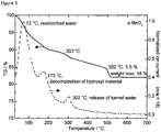
- thermogravimetric measurements in synthetic air coupled with mass spectrometry is shown in Figure 3 .
- the mass loss observed at 502 °C is assigned to the oxygen loss due to the conversion of MnO 2 to Mn 2 O 3 , in agreement with the XRD results.
- the total weight loss up to 700 °C is 18 wt %.
- the calculated mass difference to the state after dehydration at 303 °C should be twice as high, than the experimentally determined difference of just 5.5 %. This indicates that part of the manganese has been in a lower oxidation state than IV from the beginning.
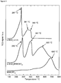
- the TPR profile of the sample calcinated for 2 h at 170 °C, in which the majority of the OH-groups should be decomposed, is shown in Figure 4 .
- the TPR profile shows two structured peaks occurring below and above approximately 380 °C.
- the low temperature peak has an early onset near 150 °C, a shoulder to the low temperature side and a narrow peak at 267 °C.
- the presence of nanoparticles of manganese oxide in the sample may cause the low onset and the shoulder as dispersed manganese oxide is more easily reduced than bigger particles.
- the first peak can be assigned to the reduction of Mn 4+ to Mn 3+ (MnO 2 to Mn 2 O 3 ).
- the reduction peak in the temperature range 300-400 °C is a superposition of two reduction steps. The first is assigned to the reduction of Mn 2 O 3 to Mn 3 O 4 and the second to that of Mn 3 O 4 to MnO.
- the presence of pure MnO x after reduction at 700 °C is confirmed by XRD (not shown). Integration of the TPR curve and comparison with the reduction profile of a pure CuO standard reveals that the average oxidation state of manganese in the starting material is Mn 3.42+ (MnO 1.71 ), in agreement with the Man:O ratio calculated from the EDX spectra.
- the s-MnO X sample consists of an amorphous material.
- the TEM micrographs. in Figure 5 show, that under the reducing conditions of prolonged electron beam irradiation the material slowly crystallizes. After 13 minutes ( Figure 5-C ) first lattice planes can be observed, which are well pronounced after 26 minutes ( Figure 5-D ).
- the Fourier transform (FFT) of the TEM image after 26 minutes, is shown in Figure 5-E .
- this result gives hardly any information about the initial oxidation state of the amorphous starting material as not only crystallization but also reduction may have been triggered by the electron beam in the microscope.
- In-situ NEXAFS measurements in the total electron yield mode which are sensitive to near-surface oxidation states, have been performed to characterize the change of the Mn valence in oxidizing conditions, i.e. with heat treatment in oxygen atmosphere.
- the Mn L-edges (L3-edge around 640-645 eV, L2 at 650-655 eV) show a rich fine structure due to a strong multiplet splitting that is very sensitive to the local chemical environment.
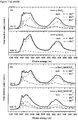
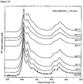
- FIG. 6(a) The evolution of the Mn valence with temperature is shown in Figure 6(a) .
- Figure 7(a) presents the experimental and fitted NEXAFS spectra at the Mn L absorption edges of the dried manganese oxide at room temperature and 400 °C in oxygen atmosphere (0.5 mbar).
- the major component in the as-prepared sample is Man 4+ , but lower oxidation states are also abundant.
- From the NEXAFS fit an average Mn oxidation state of a hypothetically homogeneous material of +3.40 can be calculated, which is in good agreement with the TPR data.
- the Mn 4+ component decreases with increasing temperature, while the Mn 3+ component increases.
- the Mn 2+ component is relatively stable, which may indicate that Man 2+ is not associated to the Mn 3+ component in a mixed valence compound like Mn 3 O 4 , but that it may rather be attributed to a surface termination in a reduced state.
- the average reduction of the material stops after an average valence of +2.90 has been reached at 300 °C.
- Heating in oxygen at 400 °C results again in oxidation with an increase in the Mn 4+ site fraction reaching an average oxidation state of +3.92.
- a reduction to lower oxidation states takes place.
- a mixture of Mn 2+ and Mn 3+ is existent with an average oxidation state of +2.80.
- the formation of crystalline Mn 3 O 4 (Hausmannite, average valence +2.67) at 550 °C is confirmed by XRD (not shown).
- the reactivity of the material depends on the oxygen partial pressure.
- TEM has shown that the material is sensitive towards electron beam irradiation, which makes the material somewhat hard to comprehensively characterize.
- the results obtained in this section will be used as reference for the supported material prepared under analogous conditions in presence of MWCNTs.
- a s-MnO X /MWCNT OX sample was prepared with a nominal content of 10.0 wet.-% Mn/C (considering that Mn from both Mn(NO 3 ) 2 and KMnO 4 will be deposited on the CNT).
- Mn from both Mn(NO 3 ) 2 and KMnO 4 will be deposited on the CNT.
- XRF analysis has shown, that the effective concentration of Mn in the sample amounts to only 6.5 ⁇ 0.5 wt.-% Mn/C.
- KMnO 4 is a strong oxidizing reagent, we surmise that a fraction did not react with the pre-adsorbed Mn 2+ ions, but was spent to oxidize defects of carbon, which have not been completely oxidized previously by the HNO 3 treatment.
- the X-ray diffraction pattern of the dried manganese oxide (110 °C), supported on MWCNTs (s-MnO X /MWCNT OX ) with 6.5 wt.-% Mn/C does not show any sharp peaks ( Figure 8 ).
- reflections of crystalline manganese oxide cannot be observed.
- the total weight loss up to 480 °C is 86 wt %. From the remaining weight of the ashes, an upper limit of the Mn loading of 8.8 8 wt % Mn/C can be calculated assuming MnO 2 as the decomposition product. This is in reasonable agreement with the concentration determined by XRF analysis.
- TPR temperature programmed reduction
- the reduction signal assigned to Mn 3+ ⁇ Mn 2+ at 397°C does not split and the intermediate formation of Mn 2 O 3 cannot be resolved.
- the third broad peak at 555 °C is attributed to the reduction of surface groups of the oxidized MWCNTs.
- the increased reactivity compared to the transition metal-free system is tentatively attributed to a catalytic function of the highly dispersed Mn oxide during thermal treatment.
- the relative increase of this high temperature TPR signal may be explained with the creation of additional defects on the CNTs due to the presence of the strong oxidant KMnO 4 during synthesis (see above).
- the Mn oxide phase in the supported sample is assumed to be identical or very similar to the s-MnO x material in the unsupported case. Assuming that reduction to MnO x is completed after the second peak, a similar average oxidation state of Mn in the starting material of Mn 3.56+ (MnO 1.78 ) can be calculated by Integration of the first two TRP signals. The presence of pure MnO after reduction at 700 °C is confirmed by XRD (not shown).
- the BET surface area decreased from 316 m 2 /g for the pure MWCNT OX to 240 m 2 /g after deposition of Mn oxide.
- the s-MnO X /MWCNT OX sample presents a typical type IV isotherm, with a clear hysteresis at high P/P 0 .
- the pore size distribution calculated from the desorption branch of the isotherm using the BJH method shows a bimodal distribution ( Figure 10 ). Pores below a diameter of 3 nm are assigned to the inner channel of the nanotubes, whereas larger pored > 10 nm are formed between the entangled nanotubes.
- Figure 10 reveals that the volume of the small pores decreased after deposition of the Mn oxide. The most likely explanation is that MnO X particles also formed at the tubes tips as well as inside the CNTs, thus blocking the inner channel of some of the CNTs.
- the THEM image of the s-MnO X /MWCNTs in Figure 11 shows a single particle of Mn 3 O 4 (Hausmannite) with a size of approximately 5 nm.
- Mn 3 O 4 Hamannite
- the particle size would not change significantly during such beam-induced reduction, and the successful nanostructuring of the Mn oxide phase by dispersion on MWCNTs is evidenced by this result.
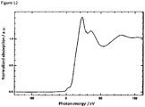
- Mn K-edge XANES Further insight into the initial oxidation state of the sample s-MnO X /MWCNT OX was provided by Mn K-edge XANES ( Figure 12 ).
- K-edge XANES is bulk sensitive. The edge position was determined to be shifted by 12.2 eV compared to that of metallic Mn reference at 6539 eV. With respect to Mn oxide references such a shift is characteristic for an average valence of ⁇ 3.4.
- the estimated depth of information in the NEXAFS experiment is here at 5-8 nm, which is in the range of particle sizes observed in TERM.
- NEXAFS is a surface sensitive method, it can be assumed, that the spectra are representative for the bulk of the present nanostructured Mn-phase.
- Figures 6b and 7b present the Mn L-edge during the calcination of the MWCNT OX supported manganese oxide in 0.25 mbar O 2 .
- the NEXAFS spectrum can be simulated with Mn 2+ and Mn 4+ species. The former may be an effect of reduction in the near-surface region of the nanoparticles.
- the average oxidation state of the sample is estimated to +3.55.
- the results obtained on the s-MnO X /MWCNT OX sample show that by symproportionation it was possible to produce a nanostructured, MWCNT OX supported manganese oxide, with similar redox properties as the unsupported manganese oxide sample s-MnO X .
- the TPR, K-edge XANES and L-edge NEXAFS analyses show that a large part of the sample is present in the oxidation state +IV.
- In-situ NEXAFS measurements confirm the variability of the oxidation state of Mn in the electrode material with variation of the pre-treatment temperature and the oxygen partial pressure.
- An i-MnO X /MWCNT OX sample was prepared with a nominal content of 5.0 wt.-% Mn/C.
- the sample was prepared by incipient wetness impregnation. Accordingly, the oxidized MWCNTs were first impregnated with water to fill their inner channel, followed by the addition of an aqueous solution of manganese(II)nitrate.
- the sample was dried following a 2-step process: first at 60 °C to allow the Mn nitrate to further spread over the surface of the sample, then at 110 °C to favor its slow dehydration and reaction with the OH groups present on the surface of the oxidized CNTs. Finally, the material was calcined at 300 °C to fully decompose the Mn precursor.
- the specific surface, measured by N 2 physisorption, is 332 m 2 /g for the calcined sample (300 °C).
- the MWCNT OX surface modified with manganese oxide particles is slightly larger than the surface of pure oxidized MWCNTs (316 m 2 /g), which may be explained with the starting decomposition of the carbon material.
- the pore size analysis reveals a slightly increasing contribution corresponding to small pores in comparison to MWCNT OX , which is in line with the small damages observed in the SEM images and which arise from the catalyzed oxidation of the CNT around the MnO X particles. Both observations point towards a different redox behavior of i-MnO X /MWCNT OX compared to s-MnO X /MWCNT OX .
- Figure 13 presents the NEXAFS study of i-MnO X /MWCNT OX and shows the Mn L-edge evolution during the simulated calcination in 0.25 mbar O 2 .
- the as-prepared material consists exclusively of Mn 2+ as is expected by impregnation with manganese(II)nitrate solution.
- this sample is first oxidized upon heating and the Mn 3+ component increases with increasing temperature. Heating to 400 °C results in a mixture of Man 2+ and Mn 3+ . The average oxidation state gradually increases from +2.0 to +2.63 at 400 °C.
- the Mn oxide particles obtained by incipient impregnation are of a size comparable to those prepared by symproportionation.
- NEXAFS NEXAFS results
- Mn 4+ a large fraction of Mn 4+ was present
- a divalent manganese species were exclusively found in i-MnO X /MWCNT OX .
- Mn centers in s-MnO X /MWCNT OX were reduced upon heating, those in i-MnO X /MWCNT OX were found to be oxidized but without the formation of Mn 4+ .
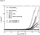
- Figure 15 compares the electrocatalytic OER activity of sand i-MnO X /MWCNT OX during linear electrode potential sweeps at neutral pH with that of the carbon support and a Pt reference electrocatalyst.
- Both MnO X /MWCNT OX composites showed high catalytic activity during the anodic voltammetric scans.
- the activity of the Mn oxide materials significantly exceeded the catalytic activity of pure Pt.
- the overpotentials of both MnO X /MWCNT OX at 2 mA cm -2 was 190 mV lower than for Pt.
- the MWCNT OX support showed only little catalytic activity and was comparable to pure Pt.
- Figure 15 also clearly highlights distinct differences in the electrochemical behavior between the two MnO X /MWCNT OX .
- a current density of 1 mA cm -2 a 20 mV lower overpotential was obtained for the s-MnO X /MWCNT OX than i-MnO X /MWCNT OX .
- i-MnO X /MWCNT OX showed a 120 mV lower overpotential than s-MnO X /MWCNT OX .
- s-MnO X /MWCNT OX reveals a lower, and hence more favorable onset potential for the OER, whereas i-MnO X /MWCNT OX is catalytically more active at higher electrode potentials and current densities.
- Atomic-scale geometric and electronic structural factors accounting for the difference in catalytic water splitting activity may include the difference in surface area between the two supported materials (332 m 2 /g for i-MnO X , while 240 m 2 /g for the s-MnO X material); also, the presence of a lower average initial oxidation state of Mn between +II and +III in the i-MnOx material compared to the s-MnOx catalyst, which could be associated with structural motifs involving more hydroxyl OH ligands rather than Mn-bridging O ligand may contribute to the observed catalytic activity trends. Based on this, we would predict that at prolonged OER relevant electrode potentials, where Mn is preferably present in the +IV state and would transform from the initial oxidation states, the two MnO x materials could gradually narrow their activity difference.
- Comparative 4 wt.-% and 10 wet.-% i-MnO X /SBA-15 samples have been prepared by the same procedure as outlined above for the i-MnO X /MWCNT OX except for using an SBA-15 mesoporous silica support.
- both SBA-15-supported MnO X samples do not show an electrocatalytic OER activity under neutral pH conditions using the electrocatalytic measurement conditions as described above. It is observed that the lacking OER activity of these SBA-15 supported samples is independent from the loading of MnO X , i.e. 4 wt.-% or 10 wt.-% MnO X , hence it is concluded that the silica support impairs the electrocatalytic OER activity, which might be due to an insufficient conductivity of the SBA-15 support.
- both the incipient wetness composite (i-MnO X /MWCNT OX ) and the symproportionation precipitation composite (s-MnO X /MWCNT OX ) are a viable water splitting electrocatalysts at neutral pH.
- the incipient wetness preparation of supported MnO X led to more active and more stable electrocatalyst than the symproportionation preparation.
- i-MnO X /MWCNT OX and s-MnO X /MWCNT OX could be caused by a variety of structural and electronic differences, such as oxidation states, Mn-O bonding and bond distances, crystallinity and long range order, or variations in surface area and dispersion on the support or in support interactions between the two MnO X materials.
- Catalyst degradation as observed in Figure 15 can be rationalized by loss of the lower Mn oxidation states or Mn ion dissolution during oxidation-reduction cycles or the formation of inactive forms of the MnO 2 species, e.g. due to changes in the crystallinity.
- the particularly beneficial effect of the i-MnO X /MWCNT OX might be caused by special effects of in-situ electro-oxidation of Mn(II) under working conditions on the material's crystallinity and defect structure compared to the effects of chemical oxidation during synthesis.
- the i-MnO X /MWCNT OX and the s-MnO X /MWCNT OX composite of the invention are both superior in the electrocatalytic splitting of water under neutral pH conditions as compared to SBA-15 silica-supported MnO X composites.
Landscapes
- Chemical & Material Sciences (AREA)
- Engineering & Computer Science (AREA)
- Materials Engineering (AREA)
- Chemical Kinetics & Catalysis (AREA)
- Electrochemistry (AREA)
- Metallurgy (AREA)
- Organic Chemistry (AREA)
- Nanotechnology (AREA)
- Inorganic Chemistry (AREA)
- Physics & Mathematics (AREA)
- Condensed Matter Physics & Semiconductors (AREA)
- General Physics & Mathematics (AREA)
- Crystallography & Structural Chemistry (AREA)
- Composite Materials (AREA)
- Catalysts (AREA)
- Inorganic Compounds Of Heavy Metals (AREA)
- Inert Electrodes (AREA)
- Battery Electrode And Active Subsutance (AREA)
Claims (4)
- Verfahren zur elektrolytischen Spaltung von Wasser unter neutralen Elektrolytbedingungen, nämlich Bedingungen, unter denen ein Elektrolyt einen pH-Wert im Bereich von 4,5 bis 8,5 aufweist, unter Verwendung eines Verbundstoffes, der einen Träger auf Kohlenstoffbasis und ein Manganoxid (MnOx) umfasst, wobei das Manganoxid nanopartikulär ist und eine Mischung aus Mn(+III) und (+IV) oder eine Mischung aus Mn(+II) und Mn(+III) umfasst.
- Verfahren nach Anspruch 1, wobei das MnOx nanopartikulär und auf dem Träger auf Kohlenstoffbasis homogen dispergiert ist und abgeschieden ist.
- Verfahren nach Anspruch 1 oder 2, wobei der Träger auf Kohlenstoffbasis eine Kohlenstoffnanoröhre (CNT) ist.
- Verfahren nach mindestens einem der Ansprüche 1 bis 3, wobei der Elektrolyt Abwasser, Meerwasser und/oder Süßwasser ist, und wobei der Verbundstoff als eine Sauerstoffentwicklungselektrode verwendet wird.
Priority Applications (1)
| Application Number | Priority Date | Filing Date | Title |
|---|---|---|---|
| EP13706277.4A EP2820172B1 (de) | 2012-02-28 | 2013-02-28 | Elektrolytische wassertrennung unter verwendung eines kohleunterstützten mnox-verbundstoffes |
Applications Claiming Priority (3)
| Application Number | Priority Date | Filing Date | Title |
|---|---|---|---|
| EP12157274.7A EP2634290A1 (de) | 2012-02-28 | 2012-02-28 | Elektrolytische Wassertrennung unter Verwendung eines kohleunterstützten MnOx-Verbundstoffes |
| EP13706277.4A EP2820172B1 (de) | 2012-02-28 | 2013-02-28 | Elektrolytische wassertrennung unter verwendung eines kohleunterstützten mnox-verbundstoffes |
| PCT/EP2013/054029 WO2013127920A1 (en) | 2012-02-28 | 2013-02-28 | ELECTROLYTIC WATER SPLITTING USING A CARBON-SUPPORTED MnOx-COMPOSITE |
Publications (2)
| Publication Number | Publication Date |
|---|---|
| EP2820172A1 EP2820172A1 (de) | 2015-01-07 |
| EP2820172B1 true EP2820172B1 (de) | 2018-02-07 |
Family
ID=47750708
Family Applications (2)
| Application Number | Title | Priority Date | Filing Date |
|---|---|---|---|
| EP12157274.7A Ceased EP2634290A1 (de) | 2012-02-28 | 2012-02-28 | Elektrolytische Wassertrennung unter Verwendung eines kohleunterstützten MnOx-Verbundstoffes |
| EP13706277.4A Not-in-force EP2820172B1 (de) | 2012-02-28 | 2013-02-28 | Elektrolytische wassertrennung unter verwendung eines kohleunterstützten mnox-verbundstoffes |
Family Applications Before (1)
| Application Number | Title | Priority Date | Filing Date |
|---|---|---|---|
| EP12157274.7A Ceased EP2634290A1 (de) | 2012-02-28 | 2012-02-28 | Elektrolytische Wassertrennung unter Verwendung eines kohleunterstützten MnOx-Verbundstoffes |
Country Status (5)
| Country | Link |
|---|---|
| US (1) | US9797052B2 (de) |
| EP (2) | EP2634290A1 (de) |
| CN (1) | CN104136661B (de) |
| DK (1) | DK2820172T3 (de) |
| WO (1) | WO2013127920A1 (de) |
Families Citing this family (28)
| Publication number | Priority date | Publication date | Assignee | Title |
|---|---|---|---|---|
| JP6614429B2 (ja) * | 2014-03-27 | 2019-12-04 | 国立研究開発法人理化学研究所 | 水分解用触媒、並びにそれを用いた酸素及び水素の製造方法 |
| US10468684B2 (en) | 2014-06-12 | 2019-11-05 | The University Of New Hampshire | Manganese oxide compositions and their use as electrodes for aqueous phase energy storage devices |
| BR112017000721A2 (en) | 2014-07-17 | 2018-01-16 | The Board Of Trustees Of The Leland Stanford Junior University | electrode for the production of water division, water electrolyzer, alkaline chlorine cell and its manufacturing method |
| KR101670929B1 (ko) * | 2014-10-21 | 2016-11-07 | 서울대학교산학협력단 | 산소 발생 촉매, 전극 및 전기화학반응 시스템 |
| US11332834B2 (en) | 2014-10-21 | 2022-05-17 | Seoul National University R&Db Foundation | Catalyst and manufacturing method thereof |
| US10385462B2 (en) * | 2015-07-09 | 2019-08-20 | Saudi Arabian Oil Company | Electrode material for electrolytic hydrogen generation |
| CN105289583A (zh) * | 2015-10-30 | 2016-02-03 | 上海纳米技术及应用国家工程研究中心有限公司 | 一种碳纳米球担载氧化锰基催化剂的制备方法 |
| US10301727B2 (en) | 2015-11-10 | 2019-05-28 | Indian Institute Of Science Education And Research | Covalent organic frameworks as porous supports for non-noble metal based water splitting electrocatalysts |
| CN105289585B (zh) * | 2015-11-30 | 2018-04-03 | 上海纳米技术及应用国家工程研究中心有限公司 | 一种用于臭氧催化剂的负载型稀土掺杂氧化锰的制备方法 |
| CN105977501B (zh) * | 2016-05-19 | 2018-10-19 | 中南大学 | 一种高性能氧还原MnO2-Mn3O4/碳纳米管复合催化剂及其制备方法和应用 |
| CN107768691A (zh) * | 2016-08-22 | 2018-03-06 | 常州优特科新能源科技有限公司 | 一种碳载锰氧化物空气电极氧催化剂的制备方法 |
| CN108114711B (zh) * | 2016-11-30 | 2021-07-16 | 中国科学院大连化学物理研究所 | 一种催化脱除臭氧的过渡金属氧化物催化剂及制备方法 |
| KR102711090B1 (ko) * | 2017-10-11 | 2024-10-02 | 몰레큘라 레바 디자인 엘엘씨 | 표적화된 산화 수준을 갖는 이산 탄소 나노튜브 및 그의 제제를 사용한 차폐 제제 |
| CN108642516B (zh) * | 2018-04-16 | 2019-10-29 | 青岛大学 | 一种室温下大面积制备自支撑高性能析氧电极的方法 |
| EP3808449A4 (de) * | 2018-06-12 | 2022-03-30 | Japan Science and Technology Agency | Katalysator und verfahren zur verwendung davon |
| CN109772410B (zh) * | 2019-02-21 | 2021-11-09 | 西南大学 | 一种高效铱基电解水双功能催化剂及其制备方法和应用 |
| CN109759054A (zh) * | 2019-02-25 | 2019-05-17 | 中国计量大学 | 一种室温分解甲醛的纳米催化剂复合材料及其制备方法 |
| AU2020313943B2 (en) * | 2019-07-15 | 2025-12-18 | William Marsh Rice University | A method for eficient electrocatalytic synthesis of pure liquid procuct solutions including H2O2, oxygenates, ammonia, and so on |
| KR102305658B1 (ko) * | 2019-08-07 | 2021-09-29 | 서울대학교산학협력단 | 전기화학반응용 전극 구조물 및 이를 포함하는 전기화학반응 시스템 |
| US11680329B2 (en) * | 2019-10-01 | 2023-06-20 | King Fahd University Of Petroleum And Minerals | Manganese oxide nanoparticle carbon microparticle electrocatalyst and method of making from Albizia procera leaf |
| CN110970630B (zh) * | 2019-11-22 | 2022-10-04 | 华南理工大学 | 一种CuO纳米片及其自上而下的制备方法与应用 |
| CN111799462A (zh) * | 2020-07-10 | 2020-10-20 | 山东交通学院 | 一种金属锰氧化物/石墨烯复合电极材料制备方法 |
| CN112853372B (zh) * | 2021-01-05 | 2024-03-22 | 辽宁大学 | 电催化剂B-MnO/CNT的制备方法及其应用 |
| CN113061922A (zh) * | 2021-03-15 | 2021-07-02 | 北京航空航天大学 | 超疏气锰氧化物析氧电极、其制备方法及氧气的电化学制备方法 |
| CN113684496B (zh) * | 2021-08-17 | 2023-03-28 | 杭州兴态环保科技有限公司 | 一种非贵金属电解水阳极材料及其制备方法和应用 |
| CN115957776B (zh) * | 2022-07-19 | 2025-08-15 | 内蒙古大学 | 用于快速分解泄露气态苯的碳布沉积锰钴氧化物制备方法 |
| CN115323397A (zh) * | 2022-08-31 | 2022-11-11 | 新疆大学 | 一种MnO2/再生脱色粉炭复合电催化剂及其制备方法 |
| CN120865840A (zh) * | 2025-09-26 | 2025-10-31 | 合肥工业大学 | 一种吸波材料及其制备方法和应用 |
Family Cites Families (11)
| Publication number | Priority date | Publication date | Assignee | Title |
|---|---|---|---|---|
| GB167041A (en) * | 1920-06-07 | 1921-08-04 | Charles Longuet Higgins | Improvements in the manufacture and production of graphite electrodes for use in electrolysis |
| EP0910340A4 (de) | 1996-03-06 | 2004-11-17 | Hyperion Catalysis Int | Funktionalisierte nanoröhren |
| DK1831440T3 (da) | 2004-11-16 | 2010-11-08 | Hyperion Catalysis Int | Fremgangsmåder til fremstilling af katalysatorer understøttet på carbonnanorørnetværk |
| EP2140934A4 (de) | 2007-03-27 | 2014-01-15 | Univ Kyoto | Katalysatormaterial zur erzeugung von sauerstoffgas aus wasser |
| US20100252445A1 (en) * | 2007-07-07 | 2010-10-07 | Donald James Highgate | Electrolysis of Salt Water |
| EP2045213A1 (de) * | 2007-10-04 | 2009-04-08 | Max-Planck-Gesellschaft zur Förderung der Wissenschaften e.V. | Anordnung von nanoröhrchengekapselten Nanofaser-Nanostruktur-Materialien |
| JP2012502467A (ja) | 2008-09-08 | 2012-01-26 | ナンヤン テクノロジカル ユニヴァーシティー | 電極材料としてのナノ粒子修飾ナノ構造材料およびその製造方法 |
| WO2010146475A1 (en) * | 2009-06-18 | 2010-12-23 | University Of The Western Cape | Supported catalysts |
| US8613900B2 (en) | 2010-01-27 | 2013-12-24 | The Regents Of The University Of California | Nanostructured transition metal oxides useful for water oxidation catalysis |
| US9365939B2 (en) * | 2011-05-31 | 2016-06-14 | Wisconsin Alumni Research Foundation | Nanoporous materials for reducing the overpotential of creating hydrogen by water electrolysis |
| US20130131399A1 (en) * | 2011-11-23 | 2013-05-23 | Celanese International Corporation | Catalyst Preparations for High Conversion Catalysts for Producing Ethanol |
-
2012
- 2012-02-28 EP EP12157274.7A patent/EP2634290A1/de not_active Ceased
-
2013
- 2013-02-28 US US14/381,706 patent/US9797052B2/en not_active Expired - Fee Related
- 2013-02-28 WO PCT/EP2013/054029 patent/WO2013127920A1/en not_active Ceased
- 2013-02-28 CN CN201380011533.3A patent/CN104136661B/zh not_active Expired - Fee Related
- 2013-02-28 EP EP13706277.4A patent/EP2820172B1/de not_active Not-in-force
- 2013-02-28 DK DK13706277.4T patent/DK2820172T3/en active
Also Published As
| Publication number | Publication date |
|---|---|
| EP2634290A1 (de) | 2013-09-04 |
| EP2820172A1 (de) | 2015-01-07 |
| US9797052B2 (en) | 2017-10-24 |
| WO2013127920A1 (en) | 2013-09-06 |
| DK2820172T3 (en) | 2018-05-22 |
| US20150068917A1 (en) | 2015-03-12 |
| CN104136661A (zh) | 2014-11-05 |
| CN104136661B (zh) | 2017-12-19 |
Similar Documents
| Publication | Publication Date | Title |
|---|---|---|
| US9797052B2 (en) | Electrolytic water splitting using a carbon-supported MnOx-composite | |
| Mette et al. | Nanostructured manganese oxide supported on carbon nanotubes for electrocatalytic water splitting | |
| Paul et al. | Morphologically controlled cobalt oxide nanoparticles for efficient oxygen evolution reaction | |
| Chang et al. | The fluorine-doped and defects engineered carbon nanosheets as advanced electrocatalysts for oxygen electroreduction | |
| Huang et al. | Rapid cationic defect and anion dual-regulated layered double hydroxides for efficient water oxidation | |
| Alegre et al. | Electrospun carbon nanofibers loaded with spinel-type cobalt oxide as bifunctional catalysts for enhanced oxygen electrocatalysis | |
| Seo et al. | Size-dependent activity trends combined with in situ X-ray absorption spectroscopy reveal insights into cobalt oxide/carbon nanotube-catalyzed bifunctional oxygen electrocatalysis | |
| Wang et al. | Intercalation and elimination of carbonate ions of NiCo layered double hydroxide for enhanced oxygen evolution catalysis | |
| Li et al. | Fe, N co-doped carbonaceous hollow spheres with self-grown carbon nanotubes as a high performance binary electrocatalyst | |
| Xu et al. | Preparation and electrocatalytic activity of 3D hierarchical porous spinel CoFe2O4 hollow nanospheres as efficient catalyst for oxygen reduction reaction and oxygen evolution reaction | |
| EP3272707A1 (de) | Nickel-eisen-diselenid-verbindung, verfahren zu deren herstellung und deren verwendung als katalysator für sauerstoffentwicklungsreaktionen | |
| Yuan et al. | Semi-sacrificial template synthesis of single-atom Ni sites supported on hollow carbon nanospheres for efficient and stable electrochemical CO 2 reduction | |
| Sahoo et al. | Nitrogen and sulfur co-doped porous carbon–is an efficient electrocatalyst as platinum or a hoax for oxygen reduction reaction in acidic environment PEM fuel cell? | |
| Wang et al. | Nanochain-structured mesoporous tungsten carbide and its superior electrocatalysis | |
| Alharbi et al. | A Nanosized Manganese-Based Chalcogenide Composite for Enhanced Electrocatalytic OER: FF Alharbi, HMT Farid | |
| KR102752602B1 (ko) | 질소 결합 CoNiFe 층상 이중 수산화물 및 그 제조방법 | |
| Dong et al. | Nitrogen-doped graphene quantum dots anchored on NiFe layered double-hydroxide nanosheets catalyze the oxygen evolution reaction | |
| Rezaei et al. | Porous magnetic iron-manganese oxide nanocubes derived from metal organic framework deposited on reduced graphene oxide nanoflake as a bi-functional electrocatalyst for hydrogen evolution and oxygen reduction reaction | |
| Balčiūnaitė et al. | Steps towards highly-efficient water splitting and oxygen reduction using nanostructured β-Ni (OH) 2 | |
| Lenarda et al. | Nanostructured carbon supported Pd-ceria as anode catalysts for anion exchange membrane fuel cells fed with polyalcohols | |
| Vaarmets et al. | Electrochemical and physical characterization of Pt–Ru alloy catalyst deposited onto microporous–mesoporous carbon support derived from Mo2C at 600 C | |
| Stamatin et al. | Influence of different carbon nanostructures on the electrocatalytic activity and stability of Pt supported electrocatalysts | |
| US20240044025A1 (en) | POROUS TiO2-x-BASED CATALYST GROWN IN SITU AND METHOD OF PREPARING THE SAME | |
| Yao et al. | Coupling SnS 2 and rGO aerogel to CuS for enhanced light-assisted OER electrocatalysis | |
| Kumar et al. | Scrutinizing the redox activity of MOF-derived Fe–Se–C and P@ Fe–Se–C species to improve overall water electrolysis and alkaline zinc–air batteries |
Legal Events
| Date | Code | Title | Description |
|---|---|---|---|
| PUAI | Public reference made under article 153(3) epc to a published international application that has entered the european phase |
Free format text: ORIGINAL CODE: 0009012 |
|
| 17P | Request for examination filed |
Effective date: 20140804 |
|
| AK | Designated contracting states |
Kind code of ref document: A1 Designated state(s): AL AT BE BG CH CY CZ DE DK EE ES FI FR GB GR HR HU IE IS IT LI LT LU LV MC MK MT NL NO PL PT RO RS SE SI SK SM TR |
|
| AX | Request for extension of the european patent |
Extension state: BA ME |
|
| DAX | Request for extension of the european patent (deleted) | ||
| 17Q | First examination report despatched |
Effective date: 20160317 |
|
| GRAP | Despatch of communication of intention to grant a patent |
Free format text: ORIGINAL CODE: EPIDOSNIGR1 |
|
| RIC1 | Information provided on ipc code assigned before grant |
Ipc: C25B 11/04 20060101ALI20170829BHEP Ipc: B01J 37/03 20060101ALI20170829BHEP Ipc: H01M 4/90 20060101ALI20170829BHEP Ipc: B01J 23/34 20060101ALI20170829BHEP Ipc: B01J 37/08 20060101ALI20170829BHEP Ipc: C25B 11/14 20060101ALI20170829BHEP Ipc: H01M 4/88 20060101ALI20170829BHEP Ipc: C25B 1/04 20060101AFI20170829BHEP Ipc: B82Y 30/00 20110101ALI20170829BHEP Ipc: B01J 37/02 20060101ALI20170829BHEP Ipc: H01M 4/92 20060101ALI20170829BHEP |
|
| INTG | Intention to grant announced |
Effective date: 20170925 |
|
| GRAS | Grant fee paid |
Free format text: ORIGINAL CODE: EPIDOSNIGR3 |
|
| GRAA | (expected) grant |
Free format text: ORIGINAL CODE: 0009210 |
|
| AK | Designated contracting states |
Kind code of ref document: B1 Designated state(s): AL AT BE BG CH CY CZ DE DK EE ES FI FR GB GR HR HU IE IS IT LI LT LU LV MC MK MT NL NO PL PT RO RS SE SI SK SM TR |
|
| REG | Reference to a national code |
Ref country code: GB Ref legal event code: FG4D |
|
| REG | Reference to a national code |
Ref country code: AT Ref legal event code: REF Ref document number: 968830 Country of ref document: AT Kind code of ref document: T Effective date: 20180215 Ref country code: CH Ref legal event code: EP |
|
| REG | Reference to a national code |
Ref country code: IE Ref legal event code: FG4D |
|
| REG | Reference to a national code |
Ref country code: DE Ref legal event code: R096 Ref document number: 602013032935 Country of ref document: DE |
|
| REG | Reference to a national code |
Ref country code: DK Ref legal event code: T3 Effective date: 20180514 |
|
| REG | Reference to a national code |
Ref country code: NL Ref legal event code: FP |
|
| REG | Reference to a national code |
Ref country code: FR Ref legal event code: PLFP Year of fee payment: 6 |
|
| REG | Reference to a national code |
Ref country code: AT Ref legal event code: MK05 Ref document number: 968830 Country of ref document: AT Kind code of ref document: T Effective date: 20180207 |
|
| PG25 | Lapsed in a contracting state [announced via postgrant information from national office to epo] |
Ref country code: FI Free format text: LAPSE BECAUSE OF FAILURE TO SUBMIT A TRANSLATION OF THE DESCRIPTION OR TO PAY THE FEE WITHIN THE PRESCRIBED TIME-LIMIT Effective date: 20180207 Ref country code: NO Free format text: LAPSE BECAUSE OF FAILURE TO SUBMIT A TRANSLATION OF THE DESCRIPTION OR TO PAY THE FEE WITHIN THE PRESCRIBED TIME-LIMIT Effective date: 20180507 Ref country code: LT Free format text: LAPSE BECAUSE OF FAILURE TO SUBMIT A TRANSLATION OF THE DESCRIPTION OR TO PAY THE FEE WITHIN THE PRESCRIBED TIME-LIMIT Effective date: 20180207 Ref country code: ES Free format text: LAPSE BECAUSE OF FAILURE TO SUBMIT A TRANSLATION OF THE DESCRIPTION OR TO PAY THE FEE WITHIN THE PRESCRIBED TIME-LIMIT Effective date: 20180207 Ref country code: CY Free format text: LAPSE BECAUSE OF FAILURE TO SUBMIT A TRANSLATION OF THE DESCRIPTION OR TO PAY THE FEE WITHIN THE PRESCRIBED TIME-LIMIT Effective date: 20180207 Ref country code: HR Free format text: LAPSE BECAUSE OF FAILURE TO SUBMIT A TRANSLATION OF THE DESCRIPTION OR TO PAY THE FEE WITHIN THE PRESCRIBED TIME-LIMIT Effective date: 20180207 |
|
| PG25 | Lapsed in a contracting state [announced via postgrant information from national office to epo] |
Ref country code: IS Free format text: LAPSE BECAUSE OF FAILURE TO SUBMIT A TRANSLATION OF THE DESCRIPTION OR TO PAY THE FEE WITHIN THE PRESCRIBED TIME-LIMIT Effective date: 20180607 Ref country code: SE Free format text: LAPSE BECAUSE OF FAILURE TO SUBMIT A TRANSLATION OF THE DESCRIPTION OR TO PAY THE FEE WITHIN THE PRESCRIBED TIME-LIMIT Effective date: 20180207 Ref country code: RS Free format text: LAPSE BECAUSE OF FAILURE TO SUBMIT A TRANSLATION OF THE DESCRIPTION OR TO PAY THE FEE WITHIN THE PRESCRIBED TIME-LIMIT Effective date: 20180207 Ref country code: GR Free format text: LAPSE BECAUSE OF FAILURE TO SUBMIT A TRANSLATION OF THE DESCRIPTION OR TO PAY THE FEE WITHIN THE PRESCRIBED TIME-LIMIT Effective date: 20180508 Ref country code: BG Free format text: LAPSE BECAUSE OF FAILURE TO SUBMIT A TRANSLATION OF THE DESCRIPTION OR TO PAY THE FEE WITHIN THE PRESCRIBED TIME-LIMIT Effective date: 20180507 Ref country code: PL Free format text: LAPSE BECAUSE OF FAILURE TO SUBMIT A TRANSLATION OF THE DESCRIPTION OR TO PAY THE FEE WITHIN THE PRESCRIBED TIME-LIMIT Effective date: 20180207 Ref country code: AT Free format text: LAPSE BECAUSE OF FAILURE TO SUBMIT A TRANSLATION OF THE DESCRIPTION OR TO PAY THE FEE WITHIN THE PRESCRIBED TIME-LIMIT Effective date: 20180207 Ref country code: LV Free format text: LAPSE BECAUSE OF FAILURE TO SUBMIT A TRANSLATION OF THE DESCRIPTION OR TO PAY THE FEE WITHIN THE PRESCRIBED TIME-LIMIT Effective date: 20180207 |
|
| PG25 | Lapsed in a contracting state [announced via postgrant information from national office to epo] |
Ref country code: EE Free format text: LAPSE BECAUSE OF FAILURE TO SUBMIT A TRANSLATION OF THE DESCRIPTION OR TO PAY THE FEE WITHIN THE PRESCRIBED TIME-LIMIT Effective date: 20180207 Ref country code: RO Free format text: LAPSE BECAUSE OF FAILURE TO SUBMIT A TRANSLATION OF THE DESCRIPTION OR TO PAY THE FEE WITHIN THE PRESCRIBED TIME-LIMIT Effective date: 20180207 Ref country code: AL Free format text: LAPSE BECAUSE OF FAILURE TO SUBMIT A TRANSLATION OF THE DESCRIPTION OR TO PAY THE FEE WITHIN THE PRESCRIBED TIME-LIMIT Effective date: 20180207 |
|
| REG | Reference to a national code |
Ref country code: DE Ref legal event code: R097 Ref document number: 602013032935 Country of ref document: DE |
|
| REG | Reference to a national code |
Ref country code: IE Ref legal event code: MM4A |
|
| REG | Reference to a national code |
Ref country code: BE Ref legal event code: MM Effective date: 20180228 |
|
| PG25 | Lapsed in a contracting state [announced via postgrant information from national office to epo] |
Ref country code: MC Free format text: LAPSE BECAUSE OF FAILURE TO SUBMIT A TRANSLATION OF THE DESCRIPTION OR TO PAY THE FEE WITHIN THE PRESCRIBED TIME-LIMIT Effective date: 20180207 Ref country code: SK Free format text: LAPSE BECAUSE OF FAILURE TO SUBMIT A TRANSLATION OF THE DESCRIPTION OR TO PAY THE FEE WITHIN THE PRESCRIBED TIME-LIMIT Effective date: 20180207 Ref country code: CZ Free format text: LAPSE BECAUSE OF FAILURE TO SUBMIT A TRANSLATION OF THE DESCRIPTION OR TO PAY THE FEE WITHIN THE PRESCRIBED TIME-LIMIT Effective date: 20180207 Ref country code: LU Free format text: LAPSE BECAUSE OF NON-PAYMENT OF DUE FEES Effective date: 20180228 Ref country code: SM Free format text: LAPSE BECAUSE OF FAILURE TO SUBMIT A TRANSLATION OF THE DESCRIPTION OR TO PAY THE FEE WITHIN THE PRESCRIBED TIME-LIMIT Effective date: 20180207 |
|
| PLBE | No opposition filed within time limit |
Free format text: ORIGINAL CODE: 0009261 |
|
| STAA | Information on the status of an ep patent application or granted ep patent |
Free format text: STATUS: NO OPPOSITION FILED WITHIN TIME LIMIT |
|
| 26N | No opposition filed |
Effective date: 20181108 |
|
| PG25 | Lapsed in a contracting state [announced via postgrant information from national office to epo] |
Ref country code: IE Free format text: LAPSE BECAUSE OF NON-PAYMENT OF DUE FEES Effective date: 20180228 |
|
| PG25 | Lapsed in a contracting state [announced via postgrant information from national office to epo] |
Ref country code: BE Free format text: LAPSE BECAUSE OF NON-PAYMENT OF DUE FEES Effective date: 20180228 Ref country code: SI Free format text: LAPSE BECAUSE OF FAILURE TO SUBMIT A TRANSLATION OF THE DESCRIPTION OR TO PAY THE FEE WITHIN THE PRESCRIBED TIME-LIMIT Effective date: 20180207 |
|
| PG25 | Lapsed in a contracting state [announced via postgrant information from national office to epo] |
Ref country code: MT Free format text: LAPSE BECAUSE OF NON-PAYMENT OF DUE FEES Effective date: 20180228 |
|
| PG25 | Lapsed in a contracting state [announced via postgrant information from national office to epo] |
Ref country code: TR Free format text: LAPSE BECAUSE OF FAILURE TO SUBMIT A TRANSLATION OF THE DESCRIPTION OR TO PAY THE FEE WITHIN THE PRESCRIBED TIME-LIMIT Effective date: 20180207 |
|
| PGFP | Annual fee paid to national office [announced via postgrant information from national office to epo] |
Ref country code: GB Payment date: 20200130 Year of fee payment: 8 Ref country code: NL Payment date: 20200224 Year of fee payment: 8 Ref country code: DE Payment date: 20200221 Year of fee payment: 8 Ref country code: IT Payment date: 20200225 Year of fee payment: 8 Ref country code: DK Payment date: 20200224 Year of fee payment: 8 |
|
| PG25 | Lapsed in a contracting state [announced via postgrant information from national office to epo] |
Ref country code: HU Free format text: LAPSE BECAUSE OF FAILURE TO SUBMIT A TRANSLATION OF THE DESCRIPTION OR TO PAY THE FEE WITHIN THE PRESCRIBED TIME-LIMIT; INVALID AB INITIO Effective date: 20130228 Ref country code: PT Free format text: LAPSE BECAUSE OF FAILURE TO SUBMIT A TRANSLATION OF THE DESCRIPTION OR TO PAY THE FEE WITHIN THE PRESCRIBED TIME-LIMIT Effective date: 20180207 |
|
| PGFP | Annual fee paid to national office [announced via postgrant information from national office to epo] |
Ref country code: CH Payment date: 20200207 Year of fee payment: 8 |
|
| PG25 | Lapsed in a contracting state [announced via postgrant information from national office to epo] |
Ref country code: MK Free format text: LAPSE BECAUSE OF NON-PAYMENT OF DUE FEES Effective date: 20180207 |
|
| PGFP | Annual fee paid to national office [announced via postgrant information from national office to epo] |
Ref country code: FR Payment date: 20200224 Year of fee payment: 8 |
|
| REG | Reference to a national code |
Ref country code: DE Ref legal event code: R119 Ref document number: 602013032935 Country of ref document: DE |
|
| REG | Reference to a national code |
Ref country code: DK Ref legal event code: EBP Effective date: 20210228 |
|
| GBPC | Gb: european patent ceased through non-payment of renewal fee |
Effective date: 20210228 |
|
| PG25 | Lapsed in a contracting state [announced via postgrant information from national office to epo] |
Ref country code: LI Free format text: LAPSE BECAUSE OF NON-PAYMENT OF DUE FEES Effective date: 20210228 Ref country code: CH Free format text: LAPSE BECAUSE OF NON-PAYMENT OF DUE FEES Effective date: 20210228 |
|
| REG | Reference to a national code |
Ref country code: NL Ref legal event code: MM Effective date: 20210301 |
|
| PG25 | Lapsed in a contracting state [announced via postgrant information from national office to epo] |
Ref country code: NL Free format text: LAPSE BECAUSE OF NON-PAYMENT OF DUE FEES Effective date: 20210301 |
|
| PG25 | Lapsed in a contracting state [announced via postgrant information from national office to epo] |
Ref country code: GB Free format text: LAPSE BECAUSE OF NON-PAYMENT OF DUE FEES Effective date: 20210228 Ref country code: FR Free format text: LAPSE BECAUSE OF NON-PAYMENT OF DUE FEES Effective date: 20210228 Ref country code: DK Free format text: LAPSE BECAUSE OF NON-PAYMENT OF DUE FEES Effective date: 20210228 Ref country code: DE Free format text: LAPSE BECAUSE OF NON-PAYMENT OF DUE FEES Effective date: 20210901 |
|
| PG25 | Lapsed in a contracting state [announced via postgrant information from national office to epo] |
Ref country code: IT Free format text: LAPSE BECAUSE OF NON-PAYMENT OF DUE FEES Effective date: 20210228 |