EP2819401B1 - Display device - Google Patents
Display device Download PDFInfo
- Publication number
- EP2819401B1 EP2819401B1 EP13751475.8A EP13751475A EP2819401B1 EP 2819401 B1 EP2819401 B1 EP 2819401B1 EP 13751475 A EP13751475 A EP 13751475A EP 2819401 B1 EP2819401 B1 EP 2819401B1
- Authority
- EP
- European Patent Office
- Prior art keywords
- user
- correcting lens
- display panel
- projection
- slide
- Prior art date
- Legal status (The legal status is an assumption and is not a legal conclusion. Google has not performed a legal analysis and makes no representation as to the accuracy of the status listed.)
- Active
Links
Images


Classifications
-
- G—PHYSICS
- G02—OPTICS
- G02B—OPTICAL ELEMENTS, SYSTEMS OR APPARATUS
- G02B27/00—Optical systems or apparatus not provided for by any of the groups G02B1/00 - G02B26/00, G02B30/00
- G02B27/01—Head-up displays
- G02B27/017—Head mounted
- G02B27/0176—Head mounted characterised by mechanical features
-
- G—PHYSICS
- G02—OPTICS
- G02B—OPTICAL ELEMENTS, SYSTEMS OR APPARATUS
- G02B27/00—Optical systems or apparatus not provided for by any of the groups G02B1/00 - G02B26/00, G02B30/00
- G02B27/01—Head-up displays
- G02B27/0149—Head-up displays characterised by mechanical features
-
- G—PHYSICS
- G02—OPTICS
- G02B—OPTICAL ELEMENTS, SYSTEMS OR APPARATUS
- G02B27/00—Optical systems or apparatus not provided for by any of the groups G02B1/00 - G02B26/00, G02B30/00
- G02B27/01—Head-up displays
- G02B27/0149—Head-up displays characterised by mechanical features
- G02B2027/015—Head-up displays characterised by mechanical features involving arrangement aiming to get less bulky devices
-
- G—PHYSICS
- G02—OPTICS
- G02B—OPTICAL ELEMENTS, SYSTEMS OR APPARATUS
- G02B27/00—Optical systems or apparatus not provided for by any of the groups G02B1/00 - G02B26/00, G02B30/00
- G02B27/01—Head-up displays
- G02B27/0149—Head-up displays characterised by mechanical features
- G02B2027/0154—Head-up displays characterised by mechanical features with movable elements
- G02B2027/0159—Head-up displays characterised by mechanical features with movable elements with mechanical means other than scaning means for positioning the whole image
-
- G—PHYSICS
- G02—OPTICS
- G02B—OPTICAL ELEMENTS, SYSTEMS OR APPARATUS
- G02B27/00—Optical systems or apparatus not provided for by any of the groups G02B1/00 - G02B26/00, G02B30/00
- G02B27/01—Head-up displays
- G02B27/017—Head mounted
- G02B2027/0178—Eyeglass type
-
- G—PHYSICS
- G02—OPTICS
- G02C—SPECTACLES; SUNGLASSES OR GOGGLES INSOFAR AS THEY HAVE THE SAME FEATURES AS SPECTACLES; CONTACT LENSES
- G02C1/00—Assemblies of lenses with bridges or browbars
- G02C1/10—Special mounting grooves in the rim or on the lens
-
- G—PHYSICS
- G02—OPTICS
- G02C—SPECTACLES; SUNGLASSES OR GOGGLES INSOFAR AS THEY HAVE THE SAME FEATURES AS SPECTACLES; CONTACT LENSES
- G02C2200/00—Generic mechanical aspects applicable to one or more of the groups G02C1/00 - G02C5/00 and G02C9/00 - G02C13/00 and their subgroups
- G02C2200/06—Locking elements
-
- G—PHYSICS
- G02—OPTICS
- G02C—SPECTACLES; SUNGLASSES OR GOGGLES INSOFAR AS THEY HAVE THE SAME FEATURES AS SPECTACLES; CONTACT LENSES
- G02C9/00—Attaching auxiliary optical parts
- G02C9/04—Attaching auxiliary optical parts by fitting over or clamping on
Definitions
- the present disclosure relates to a display device, particularly to a display device that is, for example, mounted for use on the face (head) of a user and has improved usability.
- glasses-type HMD Head Mounted Display
- the glasses-type HMD is designed to have almost no space between the face of a user and the glasses-type HMD when worn by the user (see, for example, Patent Literature 1).
- US 2004/0240072 discloses an HMD device, comprising a frame, which is mountable on the head of a user, an image-generating device mounted on said frame and comprising projection optics, a connecting device and glasses for correcting an eye deficiency of the user, said glasses not having sides and said glasses being releasably connectable with said frame by said connecting device, said glasses being arranged following said projection optics when the glasses are connected with the frame.
- WO 2011/062591 discloses a primarily reflective-based head mounted display device, for displaying and viewing visual content from a visual display source, including a frame, at least one optics housing connected to said frame, wherein the optics housing and frame are configured such that the optics housing may be positioned at least partially in front of an eye of a user, and wherein the optics housing includes a light-emitting visual source disposed within the optics housing for projecting visual content, and a plurality of reflective optical surfaces in optical communication with the light-emitting visual source that are configured to reflect a projection of the visual content into the eye of the user.
- US 5587747 discloses an interchangeable eyeglass lens system for sunglasses and other eyewear so that more than one pair of lenses can be used with a particular frame.
- Lenses particularly adapted for interchangeability and having concavities on the lens periphery for engaging fastener devices, such as studs, resilient tangs, and spring loaded detents on the frame, are included in the system, which allows for the use of a relatively expensive or rigid frame without compromising the structural integrity of the overall eyeglass set.
- a complete system would have a pair of removable lenses, a frame having a nosebridge which can be removable also, and fasteners mounted on or within the frame or nosebridge for releasably holding the lenses in place on the frame by interengaging the concavities on the lenses.
- a removable nosebridge with antirotational device, and a spring loaded detent system adapted for use in the system are disclosed, as is a method of removably attaching a lens to the frame of the invention.
- US 7553014 B2 discloses a spectacle frame comprising a spectacle frame front, the spectacle frame front comprising a pair of spaced apart and opposed arms, each of the pair at least one of the arms having an outer end thereof remote from an upper portion of the spectacle frame front, the outer end of at least one arm of the pair of arms comprising a lens retainer integral therewith for gripping and retaining a lens between the pair of spaced apart and opposed arms.
- Patent Literature 1 JP 2010-145859A
- a user may wear a glasses-type HMD for use with the user's glasses for vision correction on.
- the present disclosure has been made in view of such a situation to improve the usability of a display device that is mounted for use on the face of a user.
- a projection unit configured to project the image on the display panel may be further included.
- the projection unit may be provided with the connecting portion.
- the display panel may allow incident light from an outside to pass through irrespective of whether or not the image is projected.
- the slide portion may fix the plate-like member by being disposed in the initial position, the plate-like member being connected to the connecting portion and disposed in an oblique direction from an outer corner to an inner corner of the eyes of the user.
- a plate-like member disposed between the eyes of the user and the display panel is connected to the connecting portion, and the slide portion fixes the plate-like member between the eyes of the user and the display panel by being disposed in a predetermined initial position and is slidable in a predetermined direction from the initial position, the plate-like member being connected to the connecting portion.
- FIG. 1 illustrates an example view as seen in an oblique direction of a glasses-type head mounted display 1 which is the present embodiment.
- the head mounted display 1 (hereinafter simply referred to as HMD 1) mainly includes a bent part 11, an image capturing unit 12, a front portion 13, display panels 14R and 14L, projection units 15R and 15L, hinges 16R and 16L, temples 17R and 17L, tips 18R and 18L, signal lines 19R and 19L, and earphones 20R and 20L.
- the HMD 1 has the same shape as glasses and is mounted for use on the face (head) of a user like glasses. That is, the HMD1 is mounted on the face of a user with a tip 18R hanging over the right ear of the user and a tip 18L hanging over the left ear of the user. Thus, the display panel 14R is disposed in front of the right eye of the user and the display panel 14L is disposed in front of the left eye of the user.
- the bend part 11 has a bow-like curved shape according to the shape of the user's face on which the HMD 1 is mounted. As illustrated in FIG. 1 , the upper portion (the upper side in FIG. 1 ) of the bent part 11 is provided with the image capturing unit 12, and the lower portion (the lower side in FIG. 1 ) of the bent part 11 is provided with the front portion 13.
- the image capturing unit 12 is a small-sized CCD (Charge Coupled Device) camera or the like which is provided in the upper middle of the bent part 11 to capture an image in front of a user equipped with the HMD 1 and to supply the image obtained by the capturing to the projection units 15R and 15L.
- CCD Charge Coupled Device
- the front portion 13 is bonded to the bottom of the bend part 11 and surrounds and supports the display panels 14R and 14L.
- slide portions 32R and 32L for fixing correcting lenses 31R and 31L are provided on the back surface of the front portion 13.
- the correcting lens 31R represents a lens for correcting (compensating) the vision of the right eye of a user
- the correcting lens 31L represents a lens for correcting the vision of the left eye of the user.
- the correcting lenses 31R and 31L and the slide portions 32R and 32L will be described in detail with reference to FIG. 2 .
- the display panel 14R is used as a screen on which an image of light is projected (displayed), the light being emitted from the projection unit 15R.
- the display panel 14R is formed of a member (for example, a colorless, transparent member) which allows incident light from the outside to pass through irrespective of whether or not an image is projected.
- a user can visually recognize the surroundings of the user through the display panel 14R while visually recognizing an image projected on the display panel 14R with the right eye of the user. This is also the case with the display panel 14L.
- the display panel 14L is configured similarly to the display panel 14R and used as a screen on which an image of light is projected (displayed), the light being emitted from the projection unit 15L.
- the projection unit 15R is what is called a pico projector and projects (emits) an image as light on the display panel 14R, the image corresponding to an image signal supplied from a reproduction device (not illustrated) or the like via the signal line 19R.
- the projection unit 15R also supplies an audio signal to the earphone 20R via a signal line for audio signals, the audio signal being supplied from a reproduction device (not illustrated) or the like via the signal line 19R.
- the projection unit 15R determines an image to be displayed on the display panel 14R based on a captured image from the image capturing unit 12, and projects the determined image as light on the display panel 14R. In this manner, the projection unit 15R can achieve AR (Augmented Reality) in which additional information is superimposed and displayed according to the captured image from the image capturing unit 12. This is also the case with the projection unit 15L.
- AR Augmented Reality
- the projection unit 15L is configured similarly to the projection unit 15R, and projects an image as light on the display panel 14L, the image corresponding to an image signal supplied from a reproduction device (not illustrated) or the like via the signal line 19L.
- the projection unit 15L also supplies an audio signal to the earphone 20L via a signal line for audio signals, the audio signal being supplied from a reproduction device (not illustrated) or the like via the signal line 19L.
- the projection unit 15L determines an image to be displayed on the display panel 14L based on a captured image from the image capturing unit 12, and emits the determined image as light to be projected on the display panel 14L.
- the projection methods by which the projection unit 15R projects an image on the display panel 14R include a first projection method and a second projection method, the first projection method by which light as an image is projected in a direction normal to the surface of the display panel 14R, the second projection method by which light as an image is projected in a direction oblique to the surface of the display panel 14R. This is also the case with the projection unit 15L.
- JP 2010-145859A The details of the first projection method are described in JP 2010-145859A , and the details of the second projection method are described in JP 2009-133999A .
- the hinge 16R connects the right end portion (near where the projection unit 15R is provided) of the bend part 11 and one end of the temple 17R.
- the hinge 16L connects the left end part (near where the projection unit 15L is provided) of the bent part 11 and one end of the temple 17L.
- the temple 17R is connected to the bend part 11 via the hinge 16R and is freely rotatable with respect to the state illustrated in FIG. 1 around the hinge 16R as a rotational axis in a direction in which the bend part 11 exists.
- the temple 17L is connected to the bend part 11 via the hinge 16L and is freely rotatable with respect to the state illustrated in FIG. 1 around the hinge 16L as a rotational axis in a direction in which the bend part 11 exists.
- the tip 18R is provided at the other end of the temple 17R and is disposed on the right ear of a user.
- the tip 18L is provided at the other end of the temple 17L and is disposed on the right ear of the user.
- the signal line 19R is a signal line which is pulled out from the projection unit 15R and is wired so as to extend along the inner side of the temple 17R, and is connected to a reproduction device (not illustrated) or the like through the inside of the tip 18R.
- the signal line 19L is a signal line which is pulled out from the projection unit 15L and is wired so as to extend along the inner side of the temple 17L, and is connected to a reproduction device (not illustrated) or the like through the inside of the tip 18L.
- the earphone 20R is connected to a signal line for audio and outputs sound corresponding to an audio signal from the projection unit 15R, the signal line being pulled out from the projection unit 15R.
- the earphone 20L is connected to a signal line for audio and outputs sound corresponding to an audio signal from the projection unit 15L, the signal line being pulled out from the projection unit 15L.
- FIG. 2 illustrates an example view of the HMD 1 as seen in a direction from below (as seen from the back surface of FIG. 1 ).
- the correcting lenses 31R and 31L and the slide portions 32R and 32L are provided on the back surface (the lower side surface in FIG 2 ) of the front portion 13.
- the correcting lens 31R is fixed by a fixing portion 32Ra ( FIG. 3 ) of the slide portion 32R with connected to a connecting portion 15Ra ( FIG. 3 ) provided in the projection unit 15R.
- the correcting lens 31L is fixed by a fixing portion of the slide portion 32L with connected to a connecting portion provided in the projection unit 15L.
- the connecting portion 15Ra may be provided, for example, on the back surface of the front portion 13 instead of the projection unit 15R.
- the correcting lenses 31R and 31L are each disposed in an oblique direction as illustrated in FIG. 2 . That is, the correcting lens 31R is disposed in an oblique direction from the outer corner to the inner corner of the right eye of a user equipped with the HMD 1, and the correcting lens 31L is disposed in an oblique direction from the outer corner to the inner corner of the left eye of the user equipped with the HMD 1.
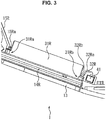
- FIG. 3 illustrates an example in which the correcting lens 31R is fixed by the fixing portion 32Ra of the slide portion 32R with connected to the connecting portion 15Ra provided in the projection unit 15R.
- the correcting lens 31 L is also fixed similarly to the case of the correcting lens 31R, and thus only the case where the correcting lens 31R is fixed will be described in FIG. 3 . This is also applied to FIGS. 4 to 6 described later.
- the projection unit 15R is provided with the connecting portion 15Ra connected to a projection portion 31Ra of the correcting lens 31R.
- the connecting portion 15Ra includes a groove to be fitted to (mated with) the projection portion 31Ra and is connected to the correcting lens 31R by fitting the projection portion 31Ra to the groove.
- the connecting portion 15Ra is not limited to a groove to be fitted to the projection portion 31Ra and may have any shape as long as the shape allows the correcting lens 31R to be connected. In the present embodiment, however, description is given under the assumption that the connecting portion 15Ra is a groove to be fitted to the projection portion 31Ra.
- the slide portion 32R is disposed in a predetermined initial position, thereby inserting the correcting lens 31R between the slide portion 32R and the connecting portion 15Ra and fixing the correcting lens 31R to the front portion 13. That is, the slide portion 32R is disposed in the initial position, thereby fixing the correcting lens 31R between the right eye of a user equipped with the HMD 1 and the display panel 14R.
- the slide portion 32R is provided with the fixing portion 32Ra for fixing the correcting lens 31R to the front portion 13.
- the fixing portion 32Ra includes a groove to be fitted to a projection portion 31Rb of the correcting lens 31R, and the projection portion 31Rb is fitted to the groove, thereby fixing the correcting lens 31R to the front portion 13, the correcting lens 31R having the projection portion 31Ra connected to the connecting portion 15Ra.
- the fixing portion 32Ra is not limited to a groove to be fitted to the projection portion 31Rb and may have any shape as long as the shape allows the correcting lens 31R to be fixed to the front portion 13. In the present embodiment, however, description is given under the assumption that the fixing portion 32Ra is a groove to be fitted to the projection portion 31Rb.
- the slide portion 32R is freely slidable from the initial position in the lower right direction in FIG . 3 parallel to the surface of the display panel 14R.
- the slide portion 32R is made to be freely slidable in the lower right direction in FIG. 3 .
- the slide portion 32R may be freely slidable in any direction as long as the fixation of the correcting lens 31R by the slide portion 32R can be released in the direction.
- the slide portion 32R is provided with an inclined face 32Rb as illustrated in FIG. 3 .
- the inclined face 32Rb is an inclined face that has an acute angle of elevation with respect to the fixing portion 32Ra in the opposite direction (the lower right direction in FIG. 3 ) to the direction (the upper left direction in FIG. 3 ) in which the connecting portion 15Ra exists.
- the inclined face 32Rb is pushed by the projection portion 31Rb of the correcting lens 31R, thereby causing the slide portion 32R to slide in the lower right direction in FIG. 3 .
- the back surface (surface in the lower right direction in FIG. 3 ) of the slide portion 32R is provided with a pressing portion 41 that presses the back surface of the slide portion 32R.
- the pressing portion 41 is configured with, for example, an elastic body (as one example, a spring or rubber) having elasticity.
- the pressing portion 41 is built in, for example, a member provided on the back surface of the slide portion 32R.
- the slide portion 32R is pressed by the pressing portion 41 in the upper left direction in FIG. 3 (the direction in which the connecting portion 15Ra exists), and is slid from a position after sliding to the initial position.
- the slide portion 32R is disposed in the initial position, thereby fixing the correcting lens 31R.
- the pressing portion 41 presses the slide portion 32R in a direction which is parallel to the surface of the display panel 14R and in which the connecting portion 15Ra exists (the upper left direction in FIG. 3 ).
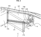
- FIG. 4 illustrates an example view of the HMD 1 illustrated in FIG. 3 as seen from the upper side in FIG. 3 .
- a user inserts the projection portion 31Ra of the correcting lens 31R into the connecting portion 15Ra of the projection unit 15R in an oblique direction.
- the user then moves (rotates) the correcting lens 31R inserted in the connecting portion 15Ra in the direction of arrow 51 (the arrow labeled with "1") illustrated in FIG. 4 around the connecting portion 15Ra as a rotation axis.
- the projection portion 31Rb of the correcting lens 31R comes into contact with the inclined face 32Rb of the slide portion 32R, and the correcting lens 31R moves so as to slide down (descend) along the inclined face 32Rb.
- the inclined face 32Rb of the slide portion 32R is pressed by the projection portion 31Rb of the correcting lens 31R according to the movement of the correcting lens 31R, and the slide portion 32R is thereby slid in the direction of arrow 52 (the arrow labeled with "2") illustrated in FIG. 4 .
- the other projection portion 31Rb is fixed by the slide portion 32R with the projection portion 31Ra of the correcting lens 31R fitted to the connecting portion 15Ra.
- FIG. 5 illustrates an example view of the HMD 1 illustrated in FIG. 4 as seen from the upper side in FIG. 4 .
- a user presses the correcting lens 31R in the direction of the arrow 51 illustrated in FIG. 5 , and the inclined face 32Rb of the slide portion 32R is thereby pressed by the projection portion 31Rb of the correcting lens 31R.
- the slide portion 32R is slid in the direction of the arrow 52 illustrated in FIG. 5 .
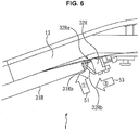
- FIG. 6 illustrates another example view of the HMD 1 illustrated in FIG. 4 as seen from the upper side in FIG. 4 .
- the projection portion 31Rb of the correcting lens 31R moves so as to slide along the inclined face 32Rb.
- the slide portion 32R is slid in the direction of arrow 53 illustrated in FIG. 6 from the position after sliding and returns to the initial position.
- the slide portion 32R is slid by the pressure of the pressing portion 41 from the position after sliding to the initial position.
- the projection portion 31Rb of the correcting lens 31R is fitted to the fixing portion 32Ra of the slide portion 32R, thereby fixing the correcting lens 31R to the front portion 13.
- the correcting lens 3 1 R When the correcting lens 31R is removed, by just sliding the slide portion 32R in the opposite direction to the direction in which the connecting portion 15Ra exists, the correcting lens 3 1 R can be easily removed from the front portion 13.
- the inventor has also invented a first mounting method as a mounting method for the correcting lens 31R, in which the correcting lens 31R and the front portion 13 are provided with a magnet, and the correcting lens 31R is mounted on the front portion 13 utilizing the attracting force of the magnet.
- the inventor has also invented a second mounting method as another mounting method, in which the front portion 13 is provided with a rail in which the projection portions 31Ra and 31Rb of the correcting lens 31R are inserted, and the correcting lens 31R is mounted in a sliding manner.
- the correcting lens 31R is not fixed to the front portion 13 using the slide portion 32R unlike the present embodiment, and thus the correcting lens 31R may come off when used.
- the inventor adopted a mechanism as a mechanism for attaching and detaching the correcting lens 31R, in which the correcting lens 31R is freely attached and detached using the slide portion 32R.
- the correcting lenses 31R and 31L are mounted on the HMD 1.
- a plate-like member for blocking ultraviolet rays or the like may be mounted optionally.
- the HMD1 for both eyes has been described as one example.
- the present technology is also applicable to an HMD for one eye (for example, an HMD having only a single display panel for one eye), as one example.
Landscapes
- Physics & Mathematics (AREA)
- General Physics & Mathematics (AREA)
- Optics & Photonics (AREA)
Applications Claiming Priority (2)
| Application Number | Priority Date | Filing Date | Title |
|---|---|---|---|
| JP2012035993A JP5942467B2 (ja) | 2012-02-22 | 2012-02-22 | 表示装置 |
| PCT/JP2013/053296 WO2013125396A1 (ja) | 2012-02-22 | 2013-02-12 | 表示装置 |
Publications (3)
| Publication Number | Publication Date |
|---|---|
| EP2819401A1 EP2819401A1 (en) | 2014-12-31 |
| EP2819401A4 EP2819401A4 (en) | 2015-10-07 |
| EP2819401B1 true EP2819401B1 (en) | 2019-09-25 |
Family
ID=49005583
Family Applications (1)
| Application Number | Title | Priority Date | Filing Date |
|---|---|---|---|
| EP13751475.8A Active EP2819401B1 (en) | 2012-02-22 | 2013-02-12 | Display device |
Country Status (5)
| Country | Link |
|---|---|
| US (1) | US20160018659A1 (https=) |
| EP (1) | EP2819401B1 (https=) |
| JP (1) | JP5942467B2 (https=) |
| CN (1) | CN104115489B (https=) |
| WO (1) | WO2013125396A1 (https=) |
Families Citing this family (12)
| Publication number | Priority date | Publication date | Assignee | Title |
|---|---|---|---|---|
| JP2014174366A (ja) * | 2013-03-11 | 2014-09-22 | Seiko Epson Corp | 虚像表示装置 |
| US10234699B2 (en) | 2013-11-26 | 2019-03-19 | Sony Corporation | Head-mounted display |
| CN104765163B (zh) * | 2015-04-27 | 2017-07-21 | 小米科技有限责任公司 | 取景信息的显示方法、装置以及智能眼镜 |
| KR101962563B1 (ko) | 2015-08-19 | 2019-03-26 | 선전 로욜 테크놀로지스 컴퍼니 리미티드 | 헤드마운트형 전자 기기 |
| JP6591659B2 (ja) | 2015-08-19 | 2019-10-16 | シェンジェン ロイオル テクノロジーズ カンパニー リミテッドShenzhen Royole Technologies Co., Ltd. | ヘッドマウント電子装置 |
| WO2017028281A1 (zh) | 2015-08-19 | 2017-02-23 | 深圳市柔宇科技有限公司 | 头戴式电子装置 |
| WO2017028282A1 (zh) | 2015-08-19 | 2017-02-23 | 深圳市柔宇科技有限公司 | 穿戴式显示设备 |
| JP2018530230A (ja) * | 2015-09-27 | 2018-10-11 | シェンジェン ロイオル テクノロジーズ カンパニー リミテッドShenzhen Royole Technologies Co., Ltd. | ヘッドマウントディスプレイデバイス |
| US10571692B2 (en) * | 2016-03-02 | 2020-02-25 | Facebook Technologies, Llc | Field curvature corrected display |
| JP6907616B2 (ja) * | 2017-03-14 | 2021-07-21 | 株式会社リコー | 立体画像の撮像・表示兼用装置及びヘッドマウント装置 |
| JP2021071603A (ja) * | 2019-10-31 | 2021-05-06 | セイコーエプソン株式会社 | ヘッドマウントディスプレイ |
| WO2024076388A1 (en) * | 2022-10-03 | 2024-04-11 | Martinez Ivan De Jesus | Projector corrective glasses |
Citations (2)
| Publication number | Priority date | Publication date | Assignee | Title |
|---|---|---|---|---|
| US20100073627A1 (en) * | 2008-09-23 | 2010-03-25 | Siu Yu | Spectacles |
| US8029132B1 (en) * | 2010-10-11 | 2011-10-04 | Korea Ogk Co., Ltd. | 3D eyeglasses with detachable front eyeglasses frame |
Family Cites Families (12)
| Publication number | Priority date | Publication date | Assignee | Title |
|---|---|---|---|---|
| US2992872A (en) * | 1958-05-12 | 1961-07-18 | Packard Bell Electronics Corp | Panel retaining means |
| US3060803A (en) * | 1959-07-27 | 1962-10-30 | Bausch & Lomb | Metallic spectacle frame supporting integral plastic lens rims and nose pads |
| US3001748A (en) * | 1959-08-03 | 1961-09-26 | Armored Luggage Mfg Co | Snap-in mirror holder |
| US4304469A (en) * | 1980-02-25 | 1981-12-08 | Solomon Charles I | Eyeglass frame having removable lenses |
| US5515116A (en) * | 1994-03-22 | 1996-05-07 | Gargoyles, Inc. | Removable eyeglass nosebridge |
| DE10311972A1 (de) * | 2003-03-18 | 2004-09-30 | Carl Zeiss | HMD-Vorrichtung |
| EP1800177B1 (en) * | 2004-09-15 | 2010-11-17 | Eye- Biz PTE Ltd. | Method and apparatus for attaching spectacle frame components and lenses |
| US7869128B2 (en) * | 2005-09-27 | 2011-01-11 | Konica Minolta Holdings, Inc. | Head mounted display |
| JP4395802B2 (ja) | 2007-11-29 | 2010-01-13 | ソニー株式会社 | 画像表示装置 |
| JP4674634B2 (ja) * | 2008-12-19 | 2011-04-20 | ソニー株式会社 | 頭部装着型ディスプレイ |
| KR20120088754A (ko) * | 2009-11-21 | 2012-08-08 | 더글라스 피터 마기아리 | 헤드 마운티드 디스플레이 장치 |
| US9291823B2 (en) * | 2012-03-30 | 2016-03-22 | Google Inc. | Wearable device with input and output structures |
-
2012
- 2012-02-22 JP JP2012035993A patent/JP5942467B2/ja not_active Expired - Fee Related
-
2013
- 2013-02-12 WO PCT/JP2013/053296 patent/WO2013125396A1/ja not_active Ceased
- 2013-02-12 EP EP13751475.8A patent/EP2819401B1/en active Active
- 2013-02-12 CN CN201380009697.2A patent/CN104115489B/zh not_active Expired - Fee Related
- 2013-02-12 US US14/377,299 patent/US20160018659A1/en not_active Abandoned
Patent Citations (2)
| Publication number | Priority date | Publication date | Assignee | Title |
|---|---|---|---|---|
| US20100073627A1 (en) * | 2008-09-23 | 2010-03-25 | Siu Yu | Spectacles |
| US8029132B1 (en) * | 2010-10-11 | 2011-10-04 | Korea Ogk Co., Ltd. | 3D eyeglasses with detachable front eyeglasses frame |
Also Published As
| Publication number | Publication date |
|---|---|
| EP2819401A4 (en) | 2015-10-07 |
| WO2013125396A1 (ja) | 2013-08-29 |
| CN104115489B (zh) | 2017-11-03 |
| EP2819401A1 (en) | 2014-12-31 |
| JP2013171224A (ja) | 2013-09-02 |
| US20160018659A1 (en) | 2016-01-21 |
| JP5942467B2 (ja) | 2016-06-29 |
| CN104115489A (zh) | 2014-10-22 |
Similar Documents
| Publication | Publication Date | Title |
|---|---|---|
| EP2819401B1 (en) | Display device | |
| US8971023B2 (en) | Wearable computing device frame | |
| JP5389493B2 (ja) | 眼鏡装着型画像表示装置 | |
| JP6083880B2 (ja) | 入出力機構を有する着用可能な装置 | |
| JP4887907B2 (ja) | 映像表示装置 | |
| CN206523700U (zh) | 头部穿戴型图像显示装置 | |
| JP2010231119A (ja) | 眼鏡型の画像表示装置 | |
| CN111602079A (zh) | 头戴式显示装置和显示系统 | |
| JP2010081272A (ja) | 眼鏡型の画像表示装置 | |
| CN100414344C (zh) | 图像显示装置 | |
| US12117611B2 (en) | System and method of augmenting a head mounted display for vision correction background | |
| JP2017181945A (ja) | 眼鏡および眼鏡装着用アタッチメント | |
| CN102269890A (zh) | 快门眼镜 | |
| US20180284452A1 (en) | Head-up display for a helmet | |
| JP2009089093A (ja) | 頭部装着型画像表示装置 | |
| EP3522524B1 (en) | Image display system | |
| JP5904756B2 (ja) | ウェアラブル機器の支持構造 | |
| KR102539026B1 (ko) | 안경 착용자의 이용 편의성이 개선된 웨어러블 디스플레이 시스템 | |
| JP2013088723A (ja) | ウェアラブル機器の取付構造、支持フレーム及び取付部材 | |
| JP2008035208A (ja) | アイグラスディスプレイ |
Legal Events
| Date | Code | Title | Description |
|---|---|---|---|
| PUAI | Public reference made under article 153(3) epc to a published international application that has entered the european phase |
Free format text: ORIGINAL CODE: 0009012 |
|
| 17P | Request for examination filed |
Effective date: 20140815 |
|
| AK | Designated contracting states |
Kind code of ref document: A1 Designated state(s): AL AT BE BG CH CY CZ DE DK EE ES FI FR GB GR HR HU IE IS IT LI LT LU LV MC MK MT NL NO PL PT RO RS SE SI SK SM TR |
|
| AX | Request for extension of the european patent |
Extension state: BA ME |
|
| DAX | Request for extension of the european patent (deleted) | ||
| RA4 | Supplementary search report drawn up and despatched (corrected) |
Effective date: 20150909 |
|
| RIC1 | Information provided on ipc code assigned before grant |
Ipc: G02C 9/00 20060101ALN20150903BHEP Ipc: G02B 27/01 20060101AFI20150903BHEP |
|
| STAA | Information on the status of an ep patent application or granted ep patent |
Free format text: STATUS: EXAMINATION IS IN PROGRESS |
|
| 17Q | First examination report despatched |
Effective date: 20180625 |
|
| REG | Reference to a national code |
Ref country code: DE Ref legal event code: R079 Ref document number: 602013060970 Country of ref document: DE Free format text: PREVIOUS MAIN CLASS: H04N0005640000 Ipc: G02B0027010000 |
|
| RIC1 | Information provided on ipc code assigned before grant |
Ipc: G02C 9/04 20060101ALN20190312BHEP Ipc: G02C 1/00 20060101ALN20190312BHEP Ipc: G02B 27/01 20060101AFI20190312BHEP |
|
| GRAP | Despatch of communication of intention to grant a patent |
Free format text: ORIGINAL CODE: EPIDOSNIGR1 |
|
| STAA | Information on the status of an ep patent application or granted ep patent |
Free format text: STATUS: GRANT OF PATENT IS INTENDED |
|
| RIC1 | Information provided on ipc code assigned before grant |
Ipc: G02B 27/01 20060101AFI20190329BHEP Ipc: G02C 9/04 20060101ALN20190329BHEP Ipc: G02C 1/00 20060101ALN20190329BHEP |
|
| INTG | Intention to grant announced |
Effective date: 20190423 |
|
| GRAS | Grant fee paid |
Free format text: ORIGINAL CODE: EPIDOSNIGR3 |
|
| GRAA | (expected) grant |
Free format text: ORIGINAL CODE: 0009210 |
|
| STAA | Information on the status of an ep patent application or granted ep patent |
Free format text: STATUS: THE PATENT HAS BEEN GRANTED |
|
| AK | Designated contracting states |
Kind code of ref document: B1 Designated state(s): AL AT BE BG CH CY CZ DE DK EE ES FI FR GB GR HR HU IE IS IT LI LT LU LV MC MK MT NL NO PL PT RO RS SE SI SK SM TR |
|
| REG | Reference to a national code |
Ref country code: GB Ref legal event code: FG4D |
|
| REG | Reference to a national code |
Ref country code: CH Ref legal event code: EP |
|
| REG | Reference to a national code |
Ref country code: AT Ref legal event code: REF Ref document number: 1184379 Country of ref document: AT Kind code of ref document: T Effective date: 20191015 |
|
| REG | Reference to a national code |
Ref country code: IE Ref legal event code: FG4D |
|
| REG | Reference to a national code |
Ref country code: DE Ref legal event code: R096 Ref document number: 602013060970 Country of ref document: DE |
|
| REG | Reference to a national code |
Ref country code: NL Ref legal event code: MP Effective date: 20190925 |
|
| PG25 | Lapsed in a contracting state [announced via postgrant information from national office to epo] |
Ref country code: HR Free format text: LAPSE BECAUSE OF FAILURE TO SUBMIT A TRANSLATION OF THE DESCRIPTION OR TO PAY THE FEE WITHIN THE PRESCRIBED TIME-LIMIT Effective date: 20190925 Ref country code: NO Free format text: LAPSE BECAUSE OF FAILURE TO SUBMIT A TRANSLATION OF THE DESCRIPTION OR TO PAY THE FEE WITHIN THE PRESCRIBED TIME-LIMIT Effective date: 20191225 Ref country code: LT Free format text: LAPSE BECAUSE OF FAILURE TO SUBMIT A TRANSLATION OF THE DESCRIPTION OR TO PAY THE FEE WITHIN THE PRESCRIBED TIME-LIMIT Effective date: 20190925 Ref country code: BG Free format text: LAPSE BECAUSE OF FAILURE TO SUBMIT A TRANSLATION OF THE DESCRIPTION OR TO PAY THE FEE WITHIN THE PRESCRIBED TIME-LIMIT Effective date: 20191225 Ref country code: FI Free format text: LAPSE BECAUSE OF FAILURE TO SUBMIT A TRANSLATION OF THE DESCRIPTION OR TO PAY THE FEE WITHIN THE PRESCRIBED TIME-LIMIT Effective date: 20190925 Ref country code: SE Free format text: LAPSE BECAUSE OF FAILURE TO SUBMIT A TRANSLATION OF THE DESCRIPTION OR TO PAY THE FEE WITHIN THE PRESCRIBED TIME-LIMIT Effective date: 20190925 |
|
| REG | Reference to a national code |
Ref country code: LT Ref legal event code: MG4D |
|
| PG25 | Lapsed in a contracting state [announced via postgrant information from national office to epo] |
Ref country code: LV Free format text: LAPSE BECAUSE OF FAILURE TO SUBMIT A TRANSLATION OF THE DESCRIPTION OR TO PAY THE FEE WITHIN THE PRESCRIBED TIME-LIMIT Effective date: 20190925 Ref country code: RS Free format text: LAPSE BECAUSE OF FAILURE TO SUBMIT A TRANSLATION OF THE DESCRIPTION OR TO PAY THE FEE WITHIN THE PRESCRIBED TIME-LIMIT Effective date: 20190925 Ref country code: GR Free format text: LAPSE BECAUSE OF FAILURE TO SUBMIT A TRANSLATION OF THE DESCRIPTION OR TO PAY THE FEE WITHIN THE PRESCRIBED TIME-LIMIT Effective date: 20191226 |
|
| REG | Reference to a national code |
Ref country code: AT Ref legal event code: MK05 Ref document number: 1184379 Country of ref document: AT Kind code of ref document: T Effective date: 20190925 |
|
| PG25 | Lapsed in a contracting state [announced via postgrant information from national office to epo] |
Ref country code: AL Free format text: LAPSE BECAUSE OF FAILURE TO SUBMIT A TRANSLATION OF THE DESCRIPTION OR TO PAY THE FEE WITHIN THE PRESCRIBED TIME-LIMIT Effective date: 20190925 Ref country code: AT Free format text: LAPSE BECAUSE OF FAILURE TO SUBMIT A TRANSLATION OF THE DESCRIPTION OR TO PAY THE FEE WITHIN THE PRESCRIBED TIME-LIMIT Effective date: 20190925 Ref country code: EE Free format text: LAPSE BECAUSE OF FAILURE TO SUBMIT A TRANSLATION OF THE DESCRIPTION OR TO PAY THE FEE WITHIN THE PRESCRIBED TIME-LIMIT Effective date: 20190925 Ref country code: RO Free format text: LAPSE BECAUSE OF FAILURE TO SUBMIT A TRANSLATION OF THE DESCRIPTION OR TO PAY THE FEE WITHIN THE PRESCRIBED TIME-LIMIT Effective date: 20190925 Ref country code: IT Free format text: LAPSE BECAUSE OF FAILURE TO SUBMIT A TRANSLATION OF THE DESCRIPTION OR TO PAY THE FEE WITHIN THE PRESCRIBED TIME-LIMIT Effective date: 20190925 Ref country code: PT Free format text: LAPSE BECAUSE OF FAILURE TO SUBMIT A TRANSLATION OF THE DESCRIPTION OR TO PAY THE FEE WITHIN THE PRESCRIBED TIME-LIMIT Effective date: 20200127 Ref country code: PL Free format text: LAPSE BECAUSE OF FAILURE TO SUBMIT A TRANSLATION OF THE DESCRIPTION OR TO PAY THE FEE WITHIN THE PRESCRIBED TIME-LIMIT Effective date: 20190925 Ref country code: NL Free format text: LAPSE BECAUSE OF FAILURE TO SUBMIT A TRANSLATION OF THE DESCRIPTION OR TO PAY THE FEE WITHIN THE PRESCRIBED TIME-LIMIT Effective date: 20190925 Ref country code: ES Free format text: LAPSE BECAUSE OF FAILURE TO SUBMIT A TRANSLATION OF THE DESCRIPTION OR TO PAY THE FEE WITHIN THE PRESCRIBED TIME-LIMIT Effective date: 20190925 |
|
| PG25 | Lapsed in a contracting state [announced via postgrant information from national office to epo] |
Ref country code: IS Free format text: LAPSE BECAUSE OF FAILURE TO SUBMIT A TRANSLATION OF THE DESCRIPTION OR TO PAY THE FEE WITHIN THE PRESCRIBED TIME-LIMIT Effective date: 20200224 Ref country code: CZ Free format text: LAPSE BECAUSE OF FAILURE TO SUBMIT A TRANSLATION OF THE DESCRIPTION OR TO PAY THE FEE WITHIN THE PRESCRIBED TIME-LIMIT Effective date: 20190925 Ref country code: SK Free format text: LAPSE BECAUSE OF FAILURE TO SUBMIT A TRANSLATION OF THE DESCRIPTION OR TO PAY THE FEE WITHIN THE PRESCRIBED TIME-LIMIT Effective date: 20190925 Ref country code: SM Free format text: LAPSE BECAUSE OF FAILURE TO SUBMIT A TRANSLATION OF THE DESCRIPTION OR TO PAY THE FEE WITHIN THE PRESCRIBED TIME-LIMIT Effective date: 20190925 |
|
| REG | Reference to a national code |
Ref country code: DE Ref legal event code: R097 Ref document number: 602013060970 Country of ref document: DE |
|
| PG2D | Information on lapse in contracting state deleted |
Ref country code: IS |
|
| PG25 | Lapsed in a contracting state [announced via postgrant information from national office to epo] |
Ref country code: DK Free format text: LAPSE BECAUSE OF FAILURE TO SUBMIT A TRANSLATION OF THE DESCRIPTION OR TO PAY THE FEE WITHIN THE PRESCRIBED TIME-LIMIT Effective date: 20190925 Ref country code: IS Free format text: LAPSE BECAUSE OF FAILURE TO SUBMIT A TRANSLATION OF THE DESCRIPTION OR TO PAY THE FEE WITHIN THE PRESCRIBED TIME-LIMIT Effective date: 20200126 |
|
| PLBE | No opposition filed within time limit |
Free format text: ORIGINAL CODE: 0009261 |
|
| STAA | Information on the status of an ep patent application or granted ep patent |
Free format text: STATUS: NO OPPOSITION FILED WITHIN TIME LIMIT |
|
| 26N | No opposition filed |
Effective date: 20200626 |
|
| REG | Reference to a national code |
Ref country code: CH Ref legal event code: PL |
|
| GBPC | Gb: european patent ceased through non-payment of renewal fee |
Effective date: 20200212 |
|
| REG | Reference to a national code |
Ref country code: BE Ref legal event code: MM Effective date: 20200229 |
|
| PG25 | Lapsed in a contracting state [announced via postgrant information from national office to epo] |
Ref country code: MC Free format text: LAPSE BECAUSE OF FAILURE TO SUBMIT A TRANSLATION OF THE DESCRIPTION OR TO PAY THE FEE WITHIN THE PRESCRIBED TIME-LIMIT Effective date: 20190925 Ref country code: LU Free format text: LAPSE BECAUSE OF NON-PAYMENT OF DUE FEES Effective date: 20200212 |
|
| PG25 | Lapsed in a contracting state [announced via postgrant information from national office to epo] |
Ref country code: SI Free format text: LAPSE BECAUSE OF FAILURE TO SUBMIT A TRANSLATION OF THE DESCRIPTION OR TO PAY THE FEE WITHIN THE PRESCRIBED TIME-LIMIT Effective date: 20190925 Ref country code: CH Free format text: LAPSE BECAUSE OF NON-PAYMENT OF DUE FEES Effective date: 20200229 Ref country code: LI Free format text: LAPSE BECAUSE OF NON-PAYMENT OF DUE FEES Effective date: 20200229 |
|
| PG25 | Lapsed in a contracting state [announced via postgrant information from national office to epo] |
Ref country code: IE Free format text: LAPSE BECAUSE OF NON-PAYMENT OF DUE FEES Effective date: 20200212 Ref country code: FR Free format text: LAPSE BECAUSE OF NON-PAYMENT OF DUE FEES Effective date: 20200229 Ref country code: GB Free format text: LAPSE BECAUSE OF NON-PAYMENT OF DUE FEES Effective date: 20200212 |
|
| PG25 | Lapsed in a contracting state [announced via postgrant information from national office to epo] |
Ref country code: BE Free format text: LAPSE BECAUSE OF NON-PAYMENT OF DUE FEES Effective date: 20200229 |
|
| PGFP | Annual fee paid to national office [announced via postgrant information from national office to epo] |
Ref country code: DE Payment date: 20210120 Year of fee payment: 9 |
|
| PG25 | Lapsed in a contracting state [announced via postgrant information from national office to epo] |
Ref country code: TR Free format text: LAPSE BECAUSE OF FAILURE TO SUBMIT A TRANSLATION OF THE DESCRIPTION OR TO PAY THE FEE WITHIN THE PRESCRIBED TIME-LIMIT Effective date: 20190925 Ref country code: MT Free format text: LAPSE BECAUSE OF FAILURE TO SUBMIT A TRANSLATION OF THE DESCRIPTION OR TO PAY THE FEE WITHIN THE PRESCRIBED TIME-LIMIT Effective date: 20190925 Ref country code: CY Free format text: LAPSE BECAUSE OF FAILURE TO SUBMIT A TRANSLATION OF THE DESCRIPTION OR TO PAY THE FEE WITHIN THE PRESCRIBED TIME-LIMIT Effective date: 20190925 |
|
| PG25 | Lapsed in a contracting state [announced via postgrant information from national office to epo] |
Ref country code: MK Free format text: LAPSE BECAUSE OF FAILURE TO SUBMIT A TRANSLATION OF THE DESCRIPTION OR TO PAY THE FEE WITHIN THE PRESCRIBED TIME-LIMIT Effective date: 20190925 |
|
| REG | Reference to a national code |
Ref country code: DE Ref legal event code: R119 Ref document number: 602013060970 Country of ref document: DE |
|
| PG25 | Lapsed in a contracting state [announced via postgrant information from national office to epo] |
Ref country code: DE Free format text: LAPSE BECAUSE OF NON-PAYMENT OF DUE FEES Effective date: 20220901 |