EP2818262A1 - Insert d'alimenteur avec pied d'alimenteur isolé - Google Patents
Insert d'alimenteur avec pied d'alimenteur isolé Download PDFInfo
- Publication number
- EP2818262A1 EP2818262A1 EP13174028.4A EP13174028A EP2818262A1 EP 2818262 A1 EP2818262 A1 EP 2818262A1 EP 13174028 A EP13174028 A EP 13174028A EP 2818262 A1 EP2818262 A1 EP 2818262A1
- Authority
- EP
- European Patent Office
- Prior art keywords
- feeder
- insulation
- molded part
- molding
- cavity
- Prior art date
- Legal status (The legal status is an assumption and is not a legal conclusion. Google has not performed a legal analysis and makes no representation as to the accuracy of the status listed.)
- Withdrawn
Links
Images
Classifications
-
- B—PERFORMING OPERATIONS; TRANSPORTING
- B22—CASTING; POWDER METALLURGY
- B22C—FOUNDRY MOULDING
- B22C9/00—Moulds or cores; Moulding processes
- B22C9/08—Features with respect to supply of molten metal, e.g. ingates, circular gates, skim gates
- B22C9/084—Breaker cores
-
- B—PERFORMING OPERATIONS; TRANSPORTING
- B22—CASTING; POWDER METALLURGY
- B22C—FOUNDRY MOULDING
- B22C9/00—Moulds or cores; Moulding processes
- B22C9/08—Features with respect to supply of molten metal, e.g. ingates, circular gates, skim gates
- B22C9/088—Feeder heads
Definitions
- the invention relates to a feeder insert for insertion into a mold used in the casting of metals, comprising a feeder comprising an inner cavity as a feeder volume, consisting of an exothermic and / or insulating material feeder body having a feeder opening for connecting the cavity with the mold cavity of the mold , and at the bottom surface facing the mold cavity there is arranged a molded part consisting of metal and having a passage opening aligned with the feed opening of the feeder body.
- a feeder insert with the aforementioned features is known from DE 201 12 425 U1 known.
- this prior art assumes that when using the known feeder insert by shaping the model including the molding of the feeder with the molding sand or a suitable molding material mixture, a sand layer between the formed by the molding metallic Feiserfuß the feeder sleeve and the during the molding process of the mold existing model surface or the subsequent mold surface set to a separation layer between form the feeder insert and the cast during the casting of the casting in the cavity of the mold forming hot metal surface of the casting.
- the feed opening of the Feiserfußes should be as close to the mold surface, so that a precise position canceling of the left after pouring due to the feeder insert on the casting escapement is ensured and expensive cleaning work on the finished casting are avoided.
- the Feederfuß also has the task to absorb the pressure exerted on the feeder insert during the molding process.
- Such metallic and possibly deformed during molding of the feeder insert in the mold moldings are also in other documents such as DE 20 2004 009 367 U1 .
- WO 2005/095020 A2 or EP 1 567 294 B1 described and are often used in foundry practice.
- Another embodiment of the feed volume of the feeder insert with the mold cavity connecting and inserting into the feeder volume during molding of the feeder insert is for example from the EP 1 850 987 B1 known.
- a metallic molded part cools the metal flowing through the molded part into the cavity of the feeder body during the casting process such that it ultimately leads to a reduction of the cross section of the through opening of the molded part due to the cold molded part walls or the molded part enclosing mold sand depositing metal comes, whereby the feeder action of the feeder sleeve is impaired. Therefore, the invention has for its object to improve a feeder insert with the generic features so that the aforementioned adverse consequence of the use of a metallic molding is at least limited.
- the invention provides that the molded part is provided with a heat-dissipation from the hot metal-reducing insulation flowing through the molded part into the cavity of the feeder body during the casting process.
- the invention has the advantage that the heat dissipation in the region of the molded part is prevented or at least reduced due to the inventively provided isolation of the metallic molding, so that the flow path for the liquid metal through the molding during the casting process over a longer period unimpaired or remains open.
- the insulation consists of a layer applied to the surface of the molding and consisting of a refractory and / or insulating material.
- the material used may be powdery or present as a fiber.
- bonding or other mechanical connection can be used for fixing the insulating material to the molded part.
- the insulation consists of a dissolving under heat material, the actual insulating effect then begins following the volatilization of the material under the action of heat by the thus created cavity forms the insulation and prevents heat transfer.
- the insulation is applied either on the inside of the molding or on the outside of the molding or on both sides of the molding, in particular, the two-sided insulation of the molded part brings with it the greatest insulation effect.
- the surface of the molding is completely provided with the insulation or even only partially with the insulation.
- a second molded part is formed on the outside of the molded part and thereby forms a gap for the air layer present therein.
- the standing between the two moldings air layer ensures the interruption of heat transfer and thus the desired insulation, which hereby still the further advantage of improved stability of the existing two moldings entire molding is improved as Suiterfuß.
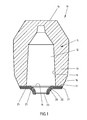
- the out FIG. 1 apparent feeder insert 10 has a feeder body 11, which comprises an inner cavity 12 as a so-called feeder volume enclosing wall portion 13 and an upper lid 14.
- a feeder body 11 which comprises an inner cavity 12 as a so-called feeder volume enclosing wall portion 13 and an upper lid 14.
- the Feeder body 11 has an outer surface 16 and an inner surface 15 enclosing the inner cavity 12 of the wall portion 13 and a bottom surface 17 in which a feeder opening 18 is formed.
- a metallic molding 20 which has a hat-shaped in the illustrated embodiment.
- this molded part can also have any other desired shape, for example as described in the documents already mentioned above.
- the hat-shaped part 20 is preferably glued to a circumferential collar 21 with the bottom surface 17 of the feeder body 11 and projects outwardly with a ring 22, wherein the free ends of the ring 22 form a passage opening 23 and which in alignment with the Feed opening 18 of the feeder body 11 is arranged so that when connected to a mold feeder insert rising from the mold cavity of the mold hot and liquid metal via the passage opening 23 and the feeder opening 18 can enter into the inner cavity 12 as feeder volume.
- an insulation of both the inner surface as well as the outer surface of the metallic molding provided by a respective layer 25 of a refractory and / or insulating material is applied to the inner surface and the outer surface.
- This material may be present in powder form or as a fiber and may preferably adhere to the surface of the metallic molding 20 by adhesion or other mechanical connection.
- a layer of a volatilized under heat material may be applied to form an insulation on the outside of the metallic molding 20, a layer of a volatilized under heat material.
- volatilization of the material deposited on the outside occurs during the casting process due to the heat given off by the hot, liquid metal, this forms a cavity between the outer wall of the molded part and the molded material surrounding it, and this cavity also exhibits an insulating effect.
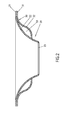
- FIG. 2 An alternative embodiment for the insulation of the metallic molding 20 is shown in FIG. 2 shown.
- a further molded part 30 is arranged, which forms a gap 33 in the assembled state with the molded part 20, and in this gap 33 pending air provides an interruption of the heat flow and thus the required insulation.
- the further, externally arranged molding 30 also has a circumferential collar 31 which is aligned in its outer end portion parallel to the circumferential collar 21 of the molding 20, so that both mold parts 20, 30 are fastened together.
- the outer molded part 30 also protrudes outwards with a ring 32 which is spaced in its course from the ring 22 of the molded part 20 in such a way that the desired intermediate space 33 is formed.
- the ring 32 of the outer molding 30 runs in its end with the rim 22 of the metallic molding 20 together.
- the second molded part 30 to be placed on the molded part 21 and bring about a connection of the two mold parts only by mutual clamping. Other types of connection of the two moldings to each other can be used.
Landscapes
- Engineering & Computer Science (AREA)
- Mechanical Engineering (AREA)
- Molds, Cores, And Manufacturing Methods Thereof (AREA)
Priority Applications (2)
| Application Number | Priority Date | Filing Date | Title |
|---|---|---|---|
| EP13174028.4A EP2818262A1 (fr) | 2013-06-27 | 2013-06-27 | Insert d'alimenteur avec pied d'alimenteur isolé |
| PCT/EP2014/063739 WO2014207221A1 (fr) | 2013-06-27 | 2014-06-27 | Manchon de masselotte à pied métallique isolé |
Applications Claiming Priority (1)
| Application Number | Priority Date | Filing Date | Title |
|---|---|---|---|
| EP13174028.4A EP2818262A1 (fr) | 2013-06-27 | 2013-06-27 | Insert d'alimenteur avec pied d'alimenteur isolé |
Publications (1)
| Publication Number | Publication Date |
|---|---|
| EP2818262A1 true EP2818262A1 (fr) | 2014-12-31 |
Family
ID=48699614
Family Applications (1)
| Application Number | Title | Priority Date | Filing Date |
|---|---|---|---|
| EP13174028.4A Withdrawn EP2818262A1 (fr) | 2013-06-27 | 2013-06-27 | Insert d'alimenteur avec pied d'alimenteur isolé |
Country Status (2)
| Country | Link |
|---|---|
| EP (1) | EP2818262A1 (fr) |
| WO (1) | WO2014207221A1 (fr) |
Cited By (1)
| Publication number | Priority date | Publication date | Assignee | Title |
|---|---|---|---|---|
| CN104985126A (zh) * | 2015-08-02 | 2015-10-21 | 邓卓伟 | 一种铸铁磨球的铸造工艺 |
Families Citing this family (2)
| Publication number | Priority date | Publication date | Assignee | Title |
|---|---|---|---|---|
| CN105618675B (zh) * | 2015-12-30 | 2019-03-15 | 山东汇金股份有限公司 | 随形覆砂冷铁的铸造方法 |
| CN114769511A (zh) * | 2022-04-13 | 2022-07-22 | 山东燕山精密机械有限公司 | 一种砂型冒口座及其应用 |
Citations (6)
| Publication number | Priority date | Publication date | Assignee | Title |
|---|---|---|---|---|
| DE3525637A1 (de) * | 1985-07-18 | 1987-01-22 | Gerhard Dipl Ing Vitt | Brechkern fuer speiser |
| DE20112425U1 (de) | 2001-07-27 | 2001-10-18 | Gtp Schaefer Giestechnische Pr | Speisereinsatz mit metallischem Speiserfuß |
| DE202004009367U1 (de) | 2004-06-15 | 2004-08-19 | GTP Schäfer Gießtechnische Produkte GmbH | Speiser mit verformbaren Metallfuß |
| WO2005095020A2 (fr) | 2004-03-31 | 2005-10-13 | AS Lüngen GmbH & Co. KG | Masselotte a manchon deformable |
| EP1567294B1 (fr) | 2003-10-28 | 2006-05-10 | Foseco International Limited | Element et systeme de masselotte pour fonderie de metaux |
| EP1850987B1 (fr) | 2005-02-23 | 2010-01-27 | AS Lüngen GmbH | Dispositif d'alimentation a douille mobile |
Family Cites Families (2)
| Publication number | Priority date | Publication date | Assignee | Title |
|---|---|---|---|---|
| DE19642838A1 (de) * | 1996-10-17 | 1997-07-31 | Daimler Benz Ag | Speiser für ein metallisches Gußwerkstück |
| EP2925466B1 (fr) * | 2012-11-29 | 2018-03-14 | GTP-Schäfer Giesstechnische Produkte GmbH | Procédé de fabrication d'une masselotte comportant un corps de masselotte exothermique ainsi qu'une coque extérieure isolante |
-
2013
- 2013-06-27 EP EP13174028.4A patent/EP2818262A1/fr not_active Withdrawn
-
2014
- 2014-06-27 WO PCT/EP2014/063739 patent/WO2014207221A1/fr active Application Filing
Patent Citations (6)
| Publication number | Priority date | Publication date | Assignee | Title |
|---|---|---|---|---|
| DE3525637A1 (de) * | 1985-07-18 | 1987-01-22 | Gerhard Dipl Ing Vitt | Brechkern fuer speiser |
| DE20112425U1 (de) | 2001-07-27 | 2001-10-18 | Gtp Schaefer Giestechnische Pr | Speisereinsatz mit metallischem Speiserfuß |
| EP1567294B1 (fr) | 2003-10-28 | 2006-05-10 | Foseco International Limited | Element et systeme de masselotte pour fonderie de metaux |
| WO2005095020A2 (fr) | 2004-03-31 | 2005-10-13 | AS Lüngen GmbH & Co. KG | Masselotte a manchon deformable |
| DE202004009367U1 (de) | 2004-06-15 | 2004-08-19 | GTP Schäfer Gießtechnische Produkte GmbH | Speiser mit verformbaren Metallfuß |
| EP1850987B1 (fr) | 2005-02-23 | 2010-01-27 | AS Lüngen GmbH | Dispositif d'alimentation a douille mobile |
Cited By (1)
| Publication number | Priority date | Publication date | Assignee | Title |
|---|---|---|---|---|
| CN104985126A (zh) * | 2015-08-02 | 2015-10-21 | 邓卓伟 | 一种铸铁磨球的铸造工艺 |
Also Published As
| Publication number | Publication date |
|---|---|
| WO2014207221A1 (fr) | 2014-12-31 |
Similar Documents
| Publication | Publication Date | Title |
|---|---|---|
| EP2097193B1 (fr) | Insert d'alimenteur et élément alimenteur | |
| DE102005008324A1 (de) | Speiser mit beweglicher Tülle | |
| EP3138642B1 (fr) | Dispositif d'alimentation comprenant un tissu reticulaire recouvrant son ouverture d'alimentation | |
| EP2818262A1 (fr) | Insert d'alimenteur avec pied d'alimenteur isolé | |
| DE102014215715A1 (de) | Anordnung zur Verwendung beim Herstellen einer teilbaren Gießform | |
| DE202013001933U1 (de) | Speisereinsatz | |
| EP3727723A1 (fr) | Procédé de production d'une partie de moule ainsi qu'insert d'alimentation destiné à être utilisé dans un tel procédé | |
| DE202004009367U1 (de) | Speiser mit verformbaren Metallfuß | |
| DE102009002057A1 (de) | Gussteil und Verfahren zur Herstellung des Gussteiles | |
| EP3141319B1 (fr) | Systeme de canal de coulee et prevu a cet effet, point de rupture pour le residu metallique restant dans le tube de section du cadre predefini | |
| EP2956256B1 (fr) | Insert de dispositif d'alimentation et procédé permettant d'agencer ledit insert dans un moule | |
| DE202016103430U1 (de) | Filterspeiser mit einem mittels Papiermanschette festgelegten Filterelement | |
| AT510737B1 (de) | Verfahren zur herstellung eines gusswerkstücks, insbesondere eines gussrads | |
| EP1779944B1 (fr) | Masselotte avec bouchon pour fermer sa entrée | |
| DE1508615A1 (de) | Giesszapfen mit Behaelter | |
| DE202013000402U1 (de) | Metall-Gießmaschine | |
| EP3695917B1 (fr) | Insert de masselotte, procédé de fabrication d'un corps de masselotte pour un insert de masselotte ainsi que pièce maîtresse et boîte à noyaux destinés à la fabrication d'un corps de masselotte | |
| EP1985392A1 (fr) | Insert d'alimenteur doté d'une zone de sol gainée | |
| EP3368234B1 (fr) | Mandrin de formage doté d'une enveloppe pouvant être élargie et modèle de coulée doté d'un mandrin de formage ainsi que procédé de coulée de métaux | |
| DE102014115848A1 (de) | Speisereinsatz mit einem in seinem Deckelbereich angeordneten Stopfen | |
| EP3094432B1 (fr) | Moule de coulée pour coulée en sable servant à fabriquer un étrier de frein | |
| EP3122436B1 (fr) | Methode de fabrication de support de filtre et support de filtre | |
| DE102013201785B3 (de) | Form zur Herstellung von Zerstäuberdüsen, Formensatz, Negativform und Verfahren zum Herstellen einer Zerstäuberdüse | |
| DE2117853C3 (de) | Verfahren zum Druck- oder Spritzgießen eines Formkörpers mit Hohlraum | |
| WO2016050264A1 (fr) | Insert d'alimentation destiné à un moule de coulée divisé verticalement |
Legal Events
| Date | Code | Title | Description |
|---|---|---|---|
| PUAI | Public reference made under article 153(3) epc to a published international application that has entered the european phase |
Free format text: ORIGINAL CODE: 0009012 |
|
| 17P | Request for examination filed |
Effective date: 20130627 |
|
| AK | Designated contracting states |
Kind code of ref document: A1 Designated state(s): AL AT BE BG CH CY CZ DE DK EE ES FI FR GB GR HR HU IE IS IT LI LT LU LV MC MK MT NL NO PL PT RO RS SE SI SK SM TR |
|
| AX | Request for extension of the european patent |
Extension state: BA ME |
|
| R17P | Request for examination filed (corrected) |
Effective date: 20150630 |
|
| RBV | Designated contracting states (corrected) |
Designated state(s): AL AT BE BG CH CY CZ DE DK EE ES FI FR GB GR HR HU IE IS IT LI LT LU LV MC MK MT NL NO PL PT RO RS SE SI SK SM TR |
|
| 17Q | First examination report despatched |
Effective date: 20160229 |
|
| STAA | Information on the status of an ep patent application or granted ep patent |
Free format text: STATUS: THE APPLICATION HAS BEEN WITHDRAWN |
|
| 18W | Application withdrawn |
Effective date: 20170125 |