EP3368234B1 - Mandrin de formage doté d'une enveloppe pouvant être élargie et modèle de coulée doté d'un mandrin de formage ainsi que procédé de coulée de métaux - Google Patents
Mandrin de formage doté d'une enveloppe pouvant être élargie et modèle de coulée doté d'un mandrin de formage ainsi que procédé de coulée de métaux Download PDFInfo
- Publication number
- EP3368234B1 EP3368234B1 EP16782282.4A EP16782282A EP3368234B1 EP 3368234 B1 EP3368234 B1 EP 3368234B1 EP 16782282 A EP16782282 A EP 16782282A EP 3368234 B1 EP3368234 B1 EP 3368234B1
- Authority
- EP
- European Patent Office
- Prior art keywords
- casting
- mandrel
- moulding
- model
- riser
- Prior art date
- Legal status (The legal status is an assumption and is not a legal conclusion. Google has not performed a legal analysis and makes no representation as to the accuracy of the status listed.)
- Active
Links
Images


Classifications
-
- B—PERFORMING OPERATIONS; TRANSPORTING
- B22—CASTING; POWDER METALLURGY
- B22C—FOUNDRY MOULDING
- B22C9/00—Moulds or cores; Moulding processes
- B22C9/08—Features with respect to supply of molten metal, e.g. ingates, circular gates, skim gates
- B22C9/088—Feeder heads
Definitions
- the invention relates to a forming mandrel for attachment to a casting model which is molded into this during the production of a casting mold used in the casting, having a foot standing on the model surface of the casting model and a receiving area arranged on the foot for receiving a to be formed therein during the production of the casting mold Feeder, the feeder with a feeder opening formed in its bottom surface facing the casting model being plugged onto the forming mandrel before molding.
- the invention also relates to a casting model having a corresponding molding mandrel and a method for casting metals using a corresponding casting model.
- the feeders must be designed in such a way that the liquid metal fed into them solidifies later than the cast part, so that material can be transported to the cast part during the solidification process, which tightly feeds the cast part.
- the feeders consist of an exothermic and / or insulating material.
- the feeders are arranged with any geometric shape at the point of the later cast part to be fed on the casting model and are firmly molded in during the creation of the casting mold by compressing an introduced molding material.
- so-called forming mandrels are known which are attached to the model surface of the respective casting model.
- Such a forming mandrel with the generic features is for example in a design as a so-called spring mandrel from the DE 10 2010 022 834 B4 known, the technical background for the arrangement of feeders and the use of forming mandrels is also described in this publication. In this respect, the explanations in DE 10 2010 022 834 B4 incorporated by reference into the disclosure of the present application.
- a forming mandrel with the features of the preamble of claim 1 is also from WO 2005/051568 A1 known.
- feeder cores which are fixed to the feeder body on the underside of the feeder body facing the casting model, are made of a refractory material and have a passage opening through which the mold cavity formed by the casting model Casting mold rising hot metal flows into the inner cavity of the feeder body or from there back into the mold cavity of the casting mold.
- the breaker cores usually produced by shooting in a shooting machine, are disc-shaped, the passage opening being formed by a constriction in the disc-shaped breaker core body in order to create a predetermined breaking point for breaking off the feeder residue from the surface of the casting.
- Such an arrangement of the feeder with a breaker core is for example from WO 20091103539 A1 known.
- the feeder moves in the direction of the casting model when the feeder is molded in the casting mold due to the mold pressure exerted, the feeder, including a breaker core that may be attached to it, usually does not come to rest on the model surface, but remains in a more or less large one Stand at a distance from it.
- the remaining cavity is filled with the liquid metal during the casting process filled in so that the predetermined breaking point provided by the breaker core is at a corresponding distance from the surface of the cast part. The resulting, more or less large riser remnants must then be removed by extensive cleaning work.
- the invention is therefore based on the object of providing a forming mandrel for fixing a feeder during the molding process, by means of which the use of an additional breaker core or other components forming a constriction associated with the feeder opening is dispensed with and yet a smaller feeder neck and an associated simple one Separation of the feeder remainder near the casting surface is made possible.
- the basic idea of the invention initially provides a forming mandrel with the features mentioned at the outset, in which on the forming mandrel an elastically expandable, elastically expandable and end-side on the foot of the forming mandrel directly on the model surface, enclosing at least its foot and / or a part of its receiving area for the feeder Adjacent casing is attached in such a way that the casing expanded before the start of molding bridges a gap that still exists between the model surface and the bottom surface of the feeder after the molding of the feeder, so that after the casting model with the mandrel attached to it has been removed from the casting mold, one through the contour the widened envelope formed predetermined breaking point for a feeder remainder remaining after completion of the casting process.
- the embodiment of the forming mandrel according to the invention has the advantage that, due to the casing which adjoins the model surface at one end and which is expanded during the molding process, it follows After demolding the casting model including the forming mandrel on the surface of the later cast part, a constriction with approximately the diameter of the foot of the forming mandrel is formed as a predetermined breaking point for the later knocking off of the feeder remainder directly on the cast part surface. This means that any cleaning effort that may still be required for removing the remains of the feeder from the cast part is significantly reduced.
- the space between the envelope and the molding mandrel is connected to a feed line for a medium to be introduced into the space, whereby according to a further embodiment of the invention this feed line is also designed as a discharge line for the medium fed into the space can be.
- this feed line is also designed as a discharge line for the medium fed into the space can be.
- a separate discharge line for the medium introduced into the intermediate space is connected to the intermediate space.
- the elastically expandable sheath is designed as a membrane made from a suitable rubber or plastic mixture.
- the forming mandrel is designed as a rigid mandrel.
- the behavior can be such that the riser does not move on the mandrel when it is being molded and the molding pressure is absorbed in the head of the riser.
- a certain displacement of the feeder on the forming mandrel can be permitted, in the context of which the upper end of the forming mandrel, which extends into an inner cavity as the feeder volume of the feeder, penetrates the cover area of the feeder opposite the bottom surface when it is moved on the forming mandrel.
- the forming mandrel is designed as a spring mandrel with a receiving area for the feeder that can be displaced against spring force relative to its foot. It can be provided here that the forming mandrel, which is designed as a spring mandrel, is designed with a foot which can be pushed into the casting model, as is the case with the generic DE 10 2010 022 834 B4 is known.
- the invention also relates to the use of a shaping mandrel designed according to the invention with a casting model, the shaping mandrel having the correspondingly disclosed elastically expandable envelope attached at the end to the foot of the shaping mandrel.
- a forming mandrel is screwed into a hole made on the model surface of the casting model or otherwise attached to the model surface, so that the expandable casing located on the forming mandrel when molding a feeder then at the beginning of the forming process in the expanded state the existing distance between the casting model and bridged over the bottom surface of the feeder placed on the forming mandrel.
- Another object of the invention relates to a casting model for the production of casting molds, in which a molding mandrel designed in accordance with the features described above is used.
- the invention relates to a method for casting metals by means of a casting mold, wherein a casting model is provided with a molding mandrel attached to it and configured in accordance with the features described above.
- a forming mandrel which has an elastically expandable sheath, requires a change in the process sequence which is otherwise usual for a rigid forming mandrel or a so-called spring mandrel.
- a feeder is plugged onto the forming mandrel, and the casing located on the forming mandrel is then placed in its expanded state.
- the casting model including the feeder fixed to it by being placed on the forming mandrel, is then molded into the casting mold by introducing a molding material, then the casing is returned to its original, unexpanded state, and then the casting model including the forming mandrel is removed from the casting mold.
- the cavity formed in the casting mold is filled with liquid metal, and after the metal has solidified, the feeder residue remaining on the metal surface of the casting is knocked off at the predetermined breaking point created by the contour of the envelope that was expanded during molding on the model surface.
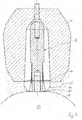
- a casting model 10 with a model surface 11 on which a forming mandrel 12 is attached is only shown schematically.
- the shaping mandrel 12 has a foot 13 and a receiving area 14 which is arranged above the foot and ends in a tip 15.
- a feeder 16 is placed on the forming mandrel 12 and has a circumferential side wall 18, a cover area 19 and a bottom surface 17.
- an inner cavity 31 is formed as a feeder volume.
- a feeder opening 20 is also arranged in the bottom surface 17, via which the liquid metal can flow into the inner cavity 31 or flow out again during the casting process.
- an elastically expandable sheath 21 in the form of a membrane made of a suitable rubber or plastic mixture is arranged on this, which is attached with its one end 22 to the foot 13 of the forming mandrel 12 in the immediate vicinity of the model surface 11 and with its the other end 23 is attached to an upper point of the receiving area 14 of the forming mandrel 12 and thereby encloses the corresponding area of the forming mandrel 12. It can be seen that an intermediate space 30 is formed between the casing 21 and the forming mandrel 12.
- the casing 21 can be brought into the space 30 by introducing a gaseous or liquid medium via an inlet and outlet line (not shown) into the in Fig. 2 shown expanded state. It can be seen here that the side area of the casing 21 is covered by a Corresponding reinforcement 24 is reinforced to the extent that under the action of the molding pressure the feeder 16 moves relative to the stationary forming mandrel 12 in the direction of the model surface 11 and thereby slides over the outer contour of the casing 21 secured with a reinforcement 24 for this purpose.
- the molding process begins after introducing a molding material 25 into the casting mold, not shown, this state is over with the filled molding material Fig. 3 evident. It can be seen that even before the start of the molding process, the expanded envelope 21 bridges the distance between the model surface 11 and into the inner cavity 31 of the feeder 16.
- Fig. 4 the position of the feeder 16 on the forming mandrel 12 after the molding pressure has been applied and the end of the molding process is shown, and it can be seen that the bottom surface 17 of the feeder 16 is still at a certain distance from the model surface 11, this distance being expanded by the Sheath 21 is still bridged. It can also be seen that due to the connection of the lower end 22 of the casing 21 to the base 13 of the forming mandrel standing on the model surface, a gusset 27 formed by the molding material 25 has set in in this area.
- the casing 21 is returned to its original shape according to FIG Fig. 1 returned by the medium introduced, for example, into the space 30 being drained off again.
- This state is in Fig. 5 shown.
- Out Fig. 5 it can be seen that the contour 26 of the molding material 25 formed by the expanded envelope during molding is maintained, which also applies to the gusset 27.
- the casting model 10 including the molding mandrel 12 has been removed from the casting mold, the cavities created thereby are filled with the liquid metal.
- the hot metal flows over the from during the casting process Molding mandrel in the path kept free in the molding material into the inner cavity 31 of the feeder 16 and back again.
- the feeder remainder 28 has a predetermined breaking point 27 a formed by the gusset 27, which is located directly on the surface of the cast part 29.
- the feeder remainder 28 can be knocked off at this predetermined breaking point 27a, the amount of cleaning that is then still required for smoothing the surface of the cast part 29 being correspondingly low.
- Fig. 6 retain the representation of the feeder, although the feeder largely loses its represented shape during the casting process.
- the forming mandrel can alternatively also be used as a so-called spring mandrel according to FIG DE 10 2010 022 834 B4 be formed, whereby there is also a displacement of the feeder 16 in the direction of the model surface 11, but without piercing the cover area of the feeder.
- the advantageous function of the shaping mandrel 12 according to the invention is also given when the shaping mandrel 12 is designed as a rigid mandrel and the force caused by the pressure exerted during the molding of the feeder is absorbed in the head of the shaping mandrel 12, so there is no displacement of the feeder 16 comes on the mandrel 12.
- the expanded envelope 21 ensures the formation of a corresponding predetermined breaking point 27a.
Landscapes
- Engineering & Computer Science (AREA)
- Mechanical Engineering (AREA)
- Moulds For Moulding Plastics Or The Like (AREA)
- Molds, Cores, And Manufacturing Methods Thereof (AREA)
Claims (10)
- Mandrin de surmoulage (12) pour la mise en place sur un modèle de moulage (10) contre-moulé dans celui-ci, lors de la fabrication d'un moule utilisé pour le moulage de métaux, , comportant un pied (13) dressé sur la surface de modèle (11) du modèle de moulage (10) et une zone de réception (14) disposée sur le pied (13) pour loger une masselotte (16) à contre-mouler dedans lors de la fabrication du moule, sachant que la masselotte (16) est emboîtée avec une ouverture de masselotte (20) constituée dans sa surface de fond (17) tournée vers le modèle de moulage (10) avant le contre-moulage sur le mandrin de surmoulage (12), caractérisé en ce que sur le mandrin de surmoulage (12), une enveloppe (21) entourant au moins le pied (13) de celui-ci et/ou une zone partielle de la zone de réception (14) de celui-ci pour la masselotte (16) est placée de façon élastiquement expansible et en extrémité sur le pied (13) du mandrin de surmoulage (12) directement raccordée de façon adjacente à la surface du modèle (11) de telle manière que l'enveloppe (21) expansée avant le début du contre-moulage comble un intervalle existant encore après le contre-moulage de la masselotte (16) à la surface de modèle (11) de telle sorte qu'après le démoulage du modèle de moulage (10) du moule avec le mandrin de surmoulage (12) placé dessus, un point de rupture théorique (27a) constitué par le profil (26) de l'enveloppe (21) expansée est constitué pour un reste de masselotte (28) métallique restant après la fin du processus de moulage, sachant qu'un espace intermédiaire (30) entre l'enveloppe (21) et le mandrin de surmoulage (12) est raccordé à un conduit d'arrivée pour un milieu à introduire dans l'espace intermédiaire (30).
- Mandrin de surmoulage (12) selon la revendication 1 pour lequel le conduit d'arrivée est également constitué comme un conduit de départ pour le milieu introduit dans l'espace intermédiaire (30).
- Mandrin de surmoulage (12) selon la revendication 1, pour lequel l'espace intermédiaire (30) est raccordé à un conduit de départ séparé pour le milieu introduit dans l'espace intermédiaire (30).
- Mandrin de surmoulage (12) selon l'une quelconque des revendications 1 à 3, pour lequel l'enveloppe (21) est constituée sous la forme d'une membrane fabriquée à partir d'un mélange approprié de caoutchouc ou de matière plastique approprié.
- Mandrin de surmoulage (12) selon l'une quelconque des revendications 1 à 4, pour lequel le mandrin de surmoulage (12) est constitué comme un mandrin rigide.
- Mandrin de surmoulage (12) selon l'une quelconque des revendications 1 à 4, pour lequel le mandrin de surmoulage (12) est constitué comme un mandrin à ressort avec une zone de réception (14) pour la masselotte (16) par rapport à son pied (13), pouvant être inséré opposé à une force de ressort.
- Mandrin de surmoulage (12) selon l'une quelconque des revendications 1 à 4, pour lequel le mandrin de surmoulage (12) est constitué comme un mandrin à ressort avec un pied pouvant être inséré dans le modèle de moulage (10) opposé à une force de ressort.
- Utilisation d'un mandrin de surmoulage (12) constitué selon l'une quelconque des revendications 1 à 7 avec un modèle de moulage (10) pour la fabrication de moules utilisés pour le moulage de métaux, sachant que le mandrin de surmoulage (12) est placé sur la surface de modèle (11) du modèle de moulage (10).
- Modèle de moulage (10) pour la fabrication de moules utilisés lors du moulage de métaux avec un mandrin de surmoulage (12) placé sur la surface du modèle (11) du modèle de moulage (10) selon l'une quelconque des revendications 1 à 7.
- Procédé de moulage de métaux au moyen d'un moule, sachant qu'un modèle de moulage (10) est préparé avec un mandrin de surmoulage (12) placé dessus, constitué selon l'une quelconque des revendications 1 à 7, pour lequel une masselotte (16) est emboîtée sur le mandrin de surmoulage (12), l'enveloppe (21) se trouvant sur le mandrin de surmoulage (12) est ensuite expansée, le modèle de moulage (10) y compris de la masselotte (16) qui y est fixée est ensuite contre-moulé dans le moule par introduction d'une matière de moulage (25), l'enveloppe est à nouveau replacée dans son état original, non expansé, le modèle de moulage (10) y compris le mandrin de surmoulage (12) est ensuite enlevé du moule, l'espace creux existant dans le moule est rempli avec le métal liquide, après solidification du métal, le reste de masselotte (28) métallique restant à la surface de la pièce moulée (29) est séparé au point de rupture théorique (27a) créé à la surface du modèle (11) par le profil (26) de l'enveloppe (21) expansée pendant le contre-moulage.
Applications Claiming Priority (2)
| Application Number | Priority Date | Filing Date | Title |
|---|---|---|---|
| DE102015118335 | 2015-10-27 | ||
| PCT/EP2016/075091 WO2017072004A1 (fr) | 2015-10-27 | 2016-10-19 | Mandrin de formage doté d'une enveloppe pouvant être élargie et modèle de coulée doté d'un mandrin de formage ainsi que procédé de coulée de métaux |
Publications (2)
| Publication Number | Publication Date |
|---|---|
| EP3368234A1 EP3368234A1 (fr) | 2018-09-05 |
| EP3368234B1 true EP3368234B1 (fr) | 2020-08-26 |
Family
ID=57144996
Family Applications (1)
| Application Number | Title | Priority Date | Filing Date |
|---|---|---|---|
| EP16782282.4A Active EP3368234B1 (fr) | 2015-10-27 | 2016-10-19 | Mandrin de formage doté d'une enveloppe pouvant être élargie et modèle de coulée doté d'un mandrin de formage ainsi que procédé de coulée de métaux |
Country Status (2)
| Country | Link |
|---|---|
| EP (1) | EP3368234B1 (fr) |
| WO (1) | WO2017072004A1 (fr) |
Families Citing this family (1)
| Publication number | Priority date | Publication date | Assignee | Title |
|---|---|---|---|---|
| DE102019102449A1 (de) * | 2019-01-31 | 2020-08-06 | Chemex Foundry Solutions Gmbh | Einteiliger Speiserkörper zur Verwendung beim Gießen von Metallen |
Family Cites Families (3)
| Publication number | Priority date | Publication date | Assignee | Title |
|---|---|---|---|---|
| GB0325134D0 (en) * | 2003-10-28 | 2003-12-03 | Foseco Int | Improved feeder element for metal casting |
| DE102008009730A1 (de) | 2008-02-19 | 2009-08-20 | AS Lüngen GmbH | Speiser mit eingestecktem Brechkern |
| DE102010022834B4 (de) | 2010-06-07 | 2012-05-31 | Ask Chemicals Feeding Systems Gmbh | Federdorn und Gießmodell mit Federdorn |
-
2016
- 2016-10-19 WO PCT/EP2016/075091 patent/WO2017072004A1/fr unknown
- 2016-10-19 EP EP16782282.4A patent/EP3368234B1/fr active Active
Non-Patent Citations (1)
| Title |
|---|
| None * |
Also Published As
| Publication number | Publication date |
|---|---|
| EP3368234A1 (fr) | 2018-09-05 |
| WO2017072004A1 (fr) | 2017-05-04 |
Similar Documents
| Publication | Publication Date | Title |
|---|---|---|
| EP1184104B1 (fr) | Insert pour masselotte | |
| EP1345716B1 (fr) | Masselotte presentant un corps tubulaire | |
| DE102006055988A1 (de) | Speisereinsatz und Speiserelement | |
| EP3003601B2 (fr) | Manchon de masselotte, élément de formage du manchon de masselotte et procédé de coulée de métal les utilisant | |
| EP1732719B1 (fr) | Masselotte a manchon deformable | |
| DE102005008324A1 (de) | Speiser mit beweglicher Tülle | |
| DE102005019385A1 (de) | Filterspeiser und Verfahren zur Herstellung einer Giessform | |
| DE102015101913B3 (de) | Eingussspeiser mit integriertem losen Filter, Gusssystem bestehend aus dem Eingussspeiser und einem Formmodell und Verfahren zur Herstellung einer Gussform | |
| DE102005025701B4 (de) | Speiser mit nachgiebigem Speiserunterteil | |
| DE202013001933U1 (de) | Speisereinsatz | |
| WO2019120804A1 (fr) | Procédé de production d'une partie de moule ainsi qu'insert d'alimentation destiné à être utilisé dans un tel procédé | |
| EP3368234B1 (fr) | Mandrin de formage doté d'une enveloppe pouvant être élargie et modèle de coulée doté d'un mandrin de formage ainsi que procédé de coulée de métaux | |
| DE202012102546U1 (de) | Einschnürspeiser (Neck-Down Feeder) | |
| EP2956256B1 (fr) | Insert de dispositif d'alimentation et procédé permettant d'agencer ledit insert dans un moule | |
| DE10142357B4 (de) | Speiser mit einem rohrähnlichen Körper | |
| DE10059481B4 (de) | Speiser mit einem rohrähnlichen Körper | |
| EP2818262A1 (fr) | Insert d'alimenteur avec pied d'alimenteur isolé | |
| DE102014207791A1 (de) | Verfahren zum Feingießen von metallischen Bauteilen | |
| DE102013111719B4 (de) | Werkzeug und Verfahren zur Trennung eines Überlaufbutzens | |
| EP2532500B1 (fr) | Procédé et dispositif de fabrication d'articles en céramique | |
| EP3695917A1 (fr) | Insert de masselotte, procédé de fabrication d'un corps de masselotte pour un insert de masselotte ainsi que pièce maîtresse et boîte à noyaux destinés à la fabrication d'un corps de masselotte | |
| EP2392425A2 (fr) | Broche et modèle de moulage avec une broche | |
| EP3100801B1 (fr) | Procede et dispositif de production d'au moins un moule presentant un systeme de memoire de page | |
| DE102013105769A1 (de) | Vorrichtung und Verfahren zum Druckgießen eines Kurbelgehäuses | |
| DE2117853C3 (de) | Verfahren zum Druck- oder Spritzgießen eines Formkörpers mit Hohlraum |
Legal Events
| Date | Code | Title | Description |
|---|---|---|---|
| STAA | Information on the status of an ep patent application or granted ep patent |
Free format text: STATUS: THE INTERNATIONAL PUBLICATION HAS BEEN MADE |
|
| PUAI | Public reference made under article 153(3) epc to a published international application that has entered the european phase |
Free format text: ORIGINAL CODE: 0009012 |
|
| STAA | Information on the status of an ep patent application or granted ep patent |
Free format text: STATUS: REQUEST FOR EXAMINATION WAS MADE |
|
| 17P | Request for examination filed |
Effective date: 20180328 |
|
| AK | Designated contracting states |
Kind code of ref document: A1 Designated state(s): AL AT BE BG CH CY CZ DE DK EE ES FI FR GB GR HR HU IE IS IT LI LT LU LV MC MK MT NL NO PL PT RO RS SE SI SK SM TR |
|
| AX | Request for extension of the european patent |
Extension state: BA ME |
|
| DAV | Request for validation of the european patent (deleted) | ||
| DAX | Request for extension of the european patent (deleted) | ||
| GRAP | Despatch of communication of intention to grant a patent |
Free format text: ORIGINAL CODE: EPIDOSNIGR1 |
|
| STAA | Information on the status of an ep patent application or granted ep patent |
Free format text: STATUS: GRANT OF PATENT IS INTENDED |
|
| INTG | Intention to grant announced |
Effective date: 20200408 |
|
| GRAS | Grant fee paid |
Free format text: ORIGINAL CODE: EPIDOSNIGR3 |
|
| GRAA | (expected) grant |
Free format text: ORIGINAL CODE: 0009210 |
|
| STAA | Information on the status of an ep patent application or granted ep patent |
Free format text: STATUS: THE PATENT HAS BEEN GRANTED |
|
| AK | Designated contracting states |
Kind code of ref document: B1 Designated state(s): AL AT BE BG CH CY CZ DE DK EE ES FI FR GB GR HR HU IE IS IT LI LT LU LV MC MK MT NL NO PL PT RO RS SE SI SK SM TR |
|
| REG | Reference to a national code |
Ref country code: GB Ref legal event code: FG4D Free format text: NOT ENGLISH |
|
| REG | Reference to a national code |
Ref country code: CH Ref legal event code: EP |
|
| REG | Reference to a national code |
Ref country code: DE Ref legal event code: R096 Ref document number: 502016010968 Country of ref document: DE |
|
| REG | Reference to a national code |
Ref country code: AT Ref legal event code: REF Ref document number: 1305887 Country of ref document: AT Kind code of ref document: T Effective date: 20200915 |
|
| REG | Reference to a national code |
Ref country code: IE Ref legal event code: FG4D Free format text: LANGUAGE OF EP DOCUMENT: GERMAN |
|
| REG | Reference to a national code |
Ref country code: LT Ref legal event code: MG4D |
|
| PG25 | Lapsed in a contracting state [announced via postgrant information from national office to epo] |
Ref country code: HR Free format text: LAPSE BECAUSE OF FAILURE TO SUBMIT A TRANSLATION OF THE DESCRIPTION OR TO PAY THE FEE WITHIN THE PRESCRIBED TIME-LIMIT Effective date: 20200826 Ref country code: SE Free format text: LAPSE BECAUSE OF FAILURE TO SUBMIT A TRANSLATION OF THE DESCRIPTION OR TO PAY THE FEE WITHIN THE PRESCRIBED TIME-LIMIT Effective date: 20200826 Ref country code: BG Free format text: LAPSE BECAUSE OF FAILURE TO SUBMIT A TRANSLATION OF THE DESCRIPTION OR TO PAY THE FEE WITHIN THE PRESCRIBED TIME-LIMIT Effective date: 20201126 Ref country code: PT Free format text: LAPSE BECAUSE OF FAILURE TO SUBMIT A TRANSLATION OF THE DESCRIPTION OR TO PAY THE FEE WITHIN THE PRESCRIBED TIME-LIMIT Effective date: 20201228 Ref country code: LT Free format text: LAPSE BECAUSE OF FAILURE TO SUBMIT A TRANSLATION OF THE DESCRIPTION OR TO PAY THE FEE WITHIN THE PRESCRIBED TIME-LIMIT Effective date: 20200826 Ref country code: FI Free format text: LAPSE BECAUSE OF FAILURE TO SUBMIT A TRANSLATION OF THE DESCRIPTION OR TO PAY THE FEE WITHIN THE PRESCRIBED TIME-LIMIT Effective date: 20200826 Ref country code: NO Free format text: LAPSE BECAUSE OF FAILURE TO SUBMIT A TRANSLATION OF THE DESCRIPTION OR TO PAY THE FEE WITHIN THE PRESCRIBED TIME-LIMIT Effective date: 20201126 Ref country code: GR Free format text: LAPSE BECAUSE OF FAILURE TO SUBMIT A TRANSLATION OF THE DESCRIPTION OR TO PAY THE FEE WITHIN THE PRESCRIBED TIME-LIMIT Effective date: 20201127 |
|
| REG | Reference to a national code |
Ref country code: NL Ref legal event code: MP Effective date: 20200826 |
|
| PG25 | Lapsed in a contracting state [announced via postgrant information from national office to epo] |
Ref country code: LV Free format text: LAPSE BECAUSE OF FAILURE TO SUBMIT A TRANSLATION OF THE DESCRIPTION OR TO PAY THE FEE WITHIN THE PRESCRIBED TIME-LIMIT Effective date: 20200826 Ref country code: RS Free format text: LAPSE BECAUSE OF FAILURE TO SUBMIT A TRANSLATION OF THE DESCRIPTION OR TO PAY THE FEE WITHIN THE PRESCRIBED TIME-LIMIT Effective date: 20200826 Ref country code: NL Free format text: LAPSE BECAUSE OF FAILURE TO SUBMIT A TRANSLATION OF THE DESCRIPTION OR TO PAY THE FEE WITHIN THE PRESCRIBED TIME-LIMIT Effective date: 20200826 Ref country code: PL Free format text: LAPSE BECAUSE OF FAILURE TO SUBMIT A TRANSLATION OF THE DESCRIPTION OR TO PAY THE FEE WITHIN THE PRESCRIBED TIME-LIMIT Effective date: 20200826 Ref country code: IS Free format text: LAPSE BECAUSE OF FAILURE TO SUBMIT A TRANSLATION OF THE DESCRIPTION OR TO PAY THE FEE WITHIN THE PRESCRIBED TIME-LIMIT Effective date: 20201226 |
|
| PG25 | Lapsed in a contracting state [announced via postgrant information from national office to epo] |
Ref country code: EE Free format text: LAPSE BECAUSE OF FAILURE TO SUBMIT A TRANSLATION OF THE DESCRIPTION OR TO PAY THE FEE WITHIN THE PRESCRIBED TIME-LIMIT Effective date: 20200826 Ref country code: SM Free format text: LAPSE BECAUSE OF FAILURE TO SUBMIT A TRANSLATION OF THE DESCRIPTION OR TO PAY THE FEE WITHIN THE PRESCRIBED TIME-LIMIT Effective date: 20200826 Ref country code: RO Free format text: LAPSE BECAUSE OF FAILURE TO SUBMIT A TRANSLATION OF THE DESCRIPTION OR TO PAY THE FEE WITHIN THE PRESCRIBED TIME-LIMIT Effective date: 20200826 Ref country code: CZ Free format text: LAPSE BECAUSE OF FAILURE TO SUBMIT A TRANSLATION OF THE DESCRIPTION OR TO PAY THE FEE WITHIN THE PRESCRIBED TIME-LIMIT Effective date: 20200826 Ref country code: DK Free format text: LAPSE BECAUSE OF FAILURE TO SUBMIT A TRANSLATION OF THE DESCRIPTION OR TO PAY THE FEE WITHIN THE PRESCRIBED TIME-LIMIT Effective date: 20200826 |
|
| REG | Reference to a national code |
Ref country code: DE Ref legal event code: R097 Ref document number: 502016010968 Country of ref document: DE |
|
| PG25 | Lapsed in a contracting state [announced via postgrant information from national office to epo] |
Ref country code: ES Free format text: LAPSE BECAUSE OF FAILURE TO SUBMIT A TRANSLATION OF THE DESCRIPTION OR TO PAY THE FEE WITHIN THE PRESCRIBED TIME-LIMIT Effective date: 20200826 Ref country code: AL Free format text: LAPSE BECAUSE OF FAILURE TO SUBMIT A TRANSLATION OF THE DESCRIPTION OR TO PAY THE FEE WITHIN THE PRESCRIBED TIME-LIMIT Effective date: 20200826 |
|
| REG | Reference to a national code |
Ref country code: CH Ref legal event code: PL |
|
| PG25 | Lapsed in a contracting state [announced via postgrant information from national office to epo] |
Ref country code: LU Free format text: LAPSE BECAUSE OF NON-PAYMENT OF DUE FEES Effective date: 20201019 Ref country code: MC Free format text: LAPSE BECAUSE OF FAILURE TO SUBMIT A TRANSLATION OF THE DESCRIPTION OR TO PAY THE FEE WITHIN THE PRESCRIBED TIME-LIMIT Effective date: 20200826 Ref country code: SK Free format text: LAPSE BECAUSE OF FAILURE TO SUBMIT A TRANSLATION OF THE DESCRIPTION OR TO PAY THE FEE WITHIN THE PRESCRIBED TIME-LIMIT Effective date: 20200826 |
|
| PLBE | No opposition filed within time limit |
Free format text: ORIGINAL CODE: 0009261 |
|
| STAA | Information on the status of an ep patent application or granted ep patent |
Free format text: STATUS: NO OPPOSITION FILED WITHIN TIME LIMIT |
|
| REG | Reference to a national code |
Ref country code: BE Ref legal event code: MM Effective date: 20201031 |
|
| GBPC | Gb: european patent ceased through non-payment of renewal fee |
Effective date: 20201126 |
|
| PG25 | Lapsed in a contracting state [announced via postgrant information from national office to epo] |
Ref country code: IT Free format text: LAPSE BECAUSE OF FAILURE TO SUBMIT A TRANSLATION OF THE DESCRIPTION OR TO PAY THE FEE WITHIN THE PRESCRIBED TIME-LIMIT Effective date: 20200826 Ref country code: FR Free format text: LAPSE BECAUSE OF NON-PAYMENT OF DUE FEES Effective date: 20201026 |
|
| 26N | No opposition filed |
Effective date: 20210527 |
|
| PG25 | Lapsed in a contracting state [announced via postgrant information from national office to epo] |
Ref country code: CH Free format text: LAPSE BECAUSE OF NON-PAYMENT OF DUE FEES Effective date: 20201031 Ref country code: BE Free format text: LAPSE BECAUSE OF NON-PAYMENT OF DUE FEES Effective date: 20201031 Ref country code: SI Free format text: LAPSE BECAUSE OF FAILURE TO SUBMIT A TRANSLATION OF THE DESCRIPTION OR TO PAY THE FEE WITHIN THE PRESCRIBED TIME-LIMIT Effective date: 20200826 Ref country code: LI Free format text: LAPSE BECAUSE OF NON-PAYMENT OF DUE FEES Effective date: 20201031 |
|
| PG25 | Lapsed in a contracting state [announced via postgrant information from national office to epo] |
Ref country code: IE Free format text: LAPSE BECAUSE OF NON-PAYMENT OF DUE FEES Effective date: 20201019 |
|
| PG25 | Lapsed in a contracting state [announced via postgrant information from national office to epo] |
Ref country code: GB Free format text: LAPSE BECAUSE OF NON-PAYMENT OF DUE FEES Effective date: 20201126 |
|
| PGFP | Annual fee paid to national office [announced via postgrant information from national office to epo] |
Ref country code: DE Payment date: 20210917 Year of fee payment: 6 Ref country code: TR Payment date: 20211018 Year of fee payment: 6 |
|
| PG25 | Lapsed in a contracting state [announced via postgrant information from national office to epo] |
Ref country code: IS Free format text: LAPSE BECAUSE OF FAILURE TO SUBMIT A TRANSLATION OF THE DESCRIPTION OR TO PAY THE FEE WITHIN THE PRESCRIBED TIME-LIMIT Effective date: 20201226 Ref country code: MT Free format text: LAPSE BECAUSE OF FAILURE TO SUBMIT A TRANSLATION OF THE DESCRIPTION OR TO PAY THE FEE WITHIN THE PRESCRIBED TIME-LIMIT Effective date: 20200826 Ref country code: CY Free format text: LAPSE BECAUSE OF FAILURE TO SUBMIT A TRANSLATION OF THE DESCRIPTION OR TO PAY THE FEE WITHIN THE PRESCRIBED TIME-LIMIT Effective date: 20200826 |
|
| PG25 | Lapsed in a contracting state [announced via postgrant information from national office to epo] |
Ref country code: MK Free format text: LAPSE BECAUSE OF FAILURE TO SUBMIT A TRANSLATION OF THE DESCRIPTION OR TO PAY THE FEE WITHIN THE PRESCRIBED TIME-LIMIT Effective date: 20200826 |
|
| REG | Reference to a national code |
Ref country code: AT Ref legal event code: MM01 Ref document number: 1305887 Country of ref document: AT Kind code of ref document: T Effective date: 20211019 |
|
| PG25 | Lapsed in a contracting state [announced via postgrant information from national office to epo] |
Ref country code: AT Free format text: LAPSE BECAUSE OF NON-PAYMENT OF DUE FEES Effective date: 20211019 |
|
| REG | Reference to a national code |
Ref country code: DE Ref legal event code: R119 Ref document number: 502016010968 Country of ref document: DE |
|
| PG25 | Lapsed in a contracting state [announced via postgrant information from national office to epo] |
Ref country code: DE Free format text: LAPSE BECAUSE OF NON-PAYMENT OF DUE FEES Effective date: 20230503 |