EP2392425A2 - Broche et modèle de moulage avec une broche - Google Patents
Broche et modèle de moulage avec une broche Download PDFInfo
- Publication number
- EP2392425A2 EP2392425A2 EP20110004527 EP11004527A EP2392425A2 EP 2392425 A2 EP2392425 A2 EP 2392425A2 EP 20110004527 EP20110004527 EP 20110004527 EP 11004527 A EP11004527 A EP 11004527A EP 2392425 A2 EP2392425 A2 EP 2392425A2
- Authority
- EP
- European Patent Office
- Prior art keywords
- spring
- foot
- mandrel
- casting
- receptacle
- Prior art date
- Legal status (The legal status is an assumption and is not a legal conclusion. Google has not performed a legal analysis and makes no representation as to the accuracy of the status listed.)
- Withdrawn
Links
Images
Classifications
-
- B—PERFORMING OPERATIONS; TRANSPORTING
- B22—CASTING; POWDER METALLURGY
- B22C—FOUNDRY MOULDING
- B22C9/00—Moulds or cores; Moulding processes
- B22C9/08—Features with respect to supply of molten metal, e.g. ingates, circular gates, skim gates
- B22C9/088—Feeder heads
Definitions
- the invention relates to a spring mandrel for insertion into a casting model for the production of casting molds and a casting model for the production of molds, with a substantially perpendicular to the surface of the casting model movable receiving mandrel for receiving a feeder.
- liquid metal is poured into a mold having a casting cavity.
- the casting cavity substantially corresponds to the negative shape of the workpiece to be produced.
- the mold comprises supply lines through which the liquid metal can be introduced into the casting cavity, and cavities, so-called feeders, which serve as surge tanks to compensate for the volume loss that occurs during the solidification of the metal and thus counteract a voids formation in the casting.
- the feeders are connected to the casting or to the vulnerable casting area and are usually arranged above or on the side of the casting cavity. After solidification of the metal remain in the feeder cavities and in the leads still metal residues that must be removed from the workpiece. In this case, it is endeavored to keep the size of these metal residues as low as possible and to design their shape so that these residues can be removed as easily and completely as possible, for example by knocking off.
- a casting model is initially provided whose contour substantially corresponds to the inner contour of the casting cavity.
- This casting model is also referred to as a model plate.
- the mold can be composed of several pieces. Accordingly, it is therefore possible that the casting model depicts only a portion of the casting.
- a holding device is usually provided on the casting model, for example a mandrel for fixing the position of the feeder or the supply line.
- a molding material as a rule molding sand, is applied to the casting model so that the feeder and the feed line are enveloped by the molding material.
- the molding material is then compressed, so that feeders and supply lines of compressed molding material are enclosed.
- Spring arbors typically include a tubular member for attachment to the casting model, a spring disposed within the tubular member, and a mandrel tip member resting on the spring and telescopically slidable in the axial direction.
- a feeder is attached to the spring mandrel. By the spring mandrel, the lower end of the feeder is kept at a distance from the surface of the casting model.
- the feeder is moved against the spring force exerted by the spring mandrel in the direction of the surface of the casting model, without the bottom of the feeder comes directly in contact with the model surface. Destruction of the feeder insert is therefore prevented even when using high compression forces.
- the feeder consists of a holding and guide part, which can be attached via a threaded pin on the model.
- a spring is placed over which a cup-shaped shell is placed, so that the jacket surrounds the spring and the upper part of the holding and guiding part, wherein the pot opening is directed downward in the direction of the model.
- the jacket can be moved in the axial direction, wherein the displacement is guided by the holding and guiding part.
- Another way to absorb the compression forces occurring during compaction of the molding sand is to provide a break point in the feeder, wherein the feeder is transferred after fracture of the fracture from a first, further spaced from the model position in a second, lying closer to the model position.
- a first and a second rigidly predetermined stop for a first and a second distance position of the feeder are specified on the mandrel.
- the surface of the casting model near distance position of the feeder passes during compaction of the molding sand by a predetermined breaking point opens in the bottom of the feeder by the counterpressure from the mandrel, whereby the feeder can go into the second distance position.
- a tube-like body which connects the cavity of the feeder with the model or in the finished mold with the cavity of the mold.
- the tube-like body has the shape of a hollow cylinder, which tapers at the end facing the casting.
- the feeder moves toward the surface of the model, displacing the feeder along the outer surface of the tubular body so as to displace the tubular body into the feeder cavity.
- the breaking edge forms controlled in the immediate vicinity of the casting cavity, so that after casting, a residual feeder remaining on the casting can be checked off in a controlled manner, without any substantial reworking of the surface of the casting is required.
- the feeder has a deformable spout, which is supported with its upper end on the underside of the feeder.
- the feeder with the deformable grommet mounted therein is slipped over a spring mandrel attached to the model.
- the deformable grommet then stands directly on the model or on the foot of the spring thorn.
- the deformable spout tapers in the direction of the model so that a breaking edge is formed.
- the feeder again moves in the direction of the model.
- the deformable spout deforms which may include, for example, a concertina-shaped element.
- the lower end of the nozzle is not displaced so that a breaking edge is formed in the immediate vicinity of the model or the casting. Even with the use of this type of feeder, therefore, it is very easy to cut off a residual feeder remaining on the casting after casting, resulting in a fracture surface which does not require any substantial post-processing.
- refractive cores are used. These are disk-shaped bodies which have a passage opening which is narrower than the opening of the feeder.
- the refractive cores are placed directly on the model and the feeders are arranged on the breaker core.
- the feeder must therefore be made very stable, which, as explained above, an increased cost of materials and thus increased costs entails.
- the break core can also be attached to the feeder, for example with an adhesive bond.
- the feeder can then be attached to the model by means of a spring pin.
- the invention therefore an object of the invention to provide a spring mandrel for use in a casting model for the production of molds, which can be used universally for all types of feeders, with all feeders destruction during compression of the molding material to be avoided.
- a foot is provided, which is provided with a receiving mandrel on which a feeder can be placed.
- the foot is arranged on a spring.
- the feeder can therefore be displaced in the axial direction, so that the reduction of the volume of the molding material occurring during compacting of the molding material and the force thereby acting on the feeder can be absorbed by an axial displacement of the feeder on the casting model.
- the spring is received in a spring receiver, which can be integrated into the casting model.
- the upper side of the foot or the underside of a plugged-on mandrel on the mandrel is positioned in the vicinity of the top of the casting model, so that a precise positioning of the feeder is possible.
- all types of feeders can be plugged, so both simple pot-shaped feeders, optionally in combination with a breaker core, tubular riser sleeves and more complex constructed feeder, such as the feeder described above with a tubular body or with a deformable spout.
- the invention is therefore a spring mandrel for insertion into a casting model for the production of molds, with an insertable into the mold model spring receptacle, which is designed so that it can be fully integrated into the casting model, a spring inserted into the spring receiving, which with its fixed end is supported on the spring receptacle, a foot supported on a free end of the spring, which is received at least in sections in the spring receptacle and displaceable therein, and a receptacle arranged on the receptacle for receiving a feeder.
- the spring receptacle of the spring mandrel according to the invention can be made of any material per se, for example made of plastic or steel sheet. It can be secured with a suitable fastener, such as screws, such as set screws, in a corresponding recess of the casting model.
- the spring receptacle can also be formed directly through a recess in the casting model.
- a spring is added.
- a coil spring is used, which is made of a suitable spring steel.
- the diameter of the spring is preferably chosen so that it fills the cross section of the spring receptacle. But it is also possible to use springs with a smaller cross-section.
- the spring is supported by one end on the spring receiver.
- the spring can also be attached to the spring receiver. But it is also possible to simply insert the spring in the spring receiver.
- the end, with which the spring is supported on the spring seat, is referred to as a fixed end, since it performs no relative movement to the casting model during the compression of the molding material.
- On the free, movable end of the spring of the foot of the mandrel is placed, which is supported at the free end of the spring.
- the foot is slidably mounted in the spring receiving, so that the foot against the force of the spring can perform an axial movement in the direction of the casting model.
- a mandrel On the side of the foot, which is the side opposite, with which the foot is supported on the spring, a mandrel is provided, with which a feeder can be centered on the foot.
- Suitable materials for foot and mandrel are, for example, metal, plastic, or wood.
- Mandrel and foot can be made in one piece. But it is also possible to make foot and mandrel separately and then connect them together.
- the receiving mandrel is preferably arranged centrally on the foot, so that a feeder, which is placed over the receiving dome, is arranged centrally on the foot.
- the locating mandrel may be provided with a centering device, through which a feeder that is slipped over the locating mandrel is centered.
- the arbor can leak at its upper end in a tip, which can come to rest on a correspondingly shaped mating surface of the feeder, so that the feeder is centered.
- the foot of the feeder, as well as the spring receptacle and the mandrel, preferably have a circular cross-section. This facilitates the positioning of the feeder, as feeders generally also have a circular cross-section.
- the peculiarity of the spring mandrel according to the invention is that the spring is not arranged in the body of the mandrel, but is received below the mandrel in a spring receptacle.
- the spring retainer is designed so that it can be fully integrated into the casting model. When installed, the spring receptacle in the spring mandrel according to the invention is thus arranged below the surface of the casting model. It is therefore much more space for the spring and the spring receptacle available, which is why the spring and the spring receptacle can be made much more robust. Larger and more stable springs can be used, and the spring retainer is much less susceptible to penetrating sand because of the significantly larger available tolerances compared to the previously used spring spikes.
- spring pins are very sensitive to penetrating sand, so that such spring pins wear relatively quickly and, for example, block when sand penetrates into the gap between the stationary and movable portion of the spring mandrel. This is a hindrance especially in automated production.
- the spring pin according to the invention is much more robust and tolerates penetration of molding sand into the spring receptacle to a much greater extent, without blocking the axial movement of the spring mandrel occurs.
- the spring receptacle can be completely integrated into a casting model.
- “fully integrated” is meant that all essential parts of the spring retainer are located below the surface of the casting model.
- Above the surface of the casting model so at best fastening elements for the spring receiving are arranged, such as tabs or a circumferential ring, which are arranged projecting from the body of the spring receptacle at the upper, open end of the spring receiving along its circumference.
- the spring receptacle is configured so that no parts are arranged above the surface of the casting model.
- the spring receptacle preferably has a cup-shaped shape. The spring inserted in the spring receiver then rests on the bottom of the pot. In other words, the free spring travel does not extend beyond the surface of the casting model.
- the spring receiver When producing a casting mold, first the spring receiver is attached to the casting model. For this purpose, corresponding, preferably circular, recesses or openings are provided on the casting model, into which the spring receptacle is inserted. This is then, as already described above, fastened by means of screws, for example, on the casting model. After the spring is inserted into the spring retainer, the foot can be used with the mounting arbor attached to the spring receptacle. But it is also possible that spring receptacle, spring and the foot are pre-assembled with mandrel provided and the pre-assembled spring mandrel is inserted into the recess provided in the casting model or opening and fastened there. This attachment can be done for example by means of springs, claws, clamps, or, as described above, also by a screw connection. Other attachment means, such as an adhesive bond, are also possible.
- the spring is preferably dimensioned to have a spring constant such that a feeder mounted on the foot with the mandrel is held in a spaced position from the surface of the casting mold.
- the foot is partially inserted into the spring retainer, so that a guide is achieved when the foot slides with its outer peripheral surface at an axial displacement along the wall of the spring retainer.
- molding sand or other suitable molding material is then abandoned and this then compacted in the usual way. In this case, moves through the pressure acting upon compression of the foot and thus also the feeder in the direction of the casting model, wherein the foot is moved further into the spring receiving into it.
- the foot can already be guided by the spring seat in the axial displacement.
- at least one guide can be provided, through which the displacement of the foot is guided in the spring receiver.
- the guide can be done by various devices.
- a guide rod can be provided in the spring receptacle in the axial direction, which is accommodated in a corresponding bore of the foot or of the receiving mandrel so that the foot or the receiving mandrel is guided along the guide pin during an axial displacement.
- It may be provided a central guide pin.
- a plurality of pins which may be arranged outside the longitudinal axis of the receiving mandrel in the spring receiving.
- It is also possible to provide on the circumference of the foot one or more grooves extending parallel to the longitudinal axis, in which corresponding, preferably strip-shaped projections engage on the lateral surfaces of the spring receptacle.
- the grooves slide during the axial displacement of the feeder then along the projections provided in the spring receiving, whereby a stabilization of the axial displacement is achieved. It is also possible to provide the grooves in the side wall of the spring retainer and the strip-shaped projections on the peripheral surface of the foot.
- the guide is formed as a guide extension, which is arranged on the side of the foot on which the foot is supported on the spring, wherein the guide extension is received in a receptacle in which the guide extension is guided.
- the guide extension is preferably designed as a cylindrical body which is centrally located centrally on the underside of the foot. This guide extension is received in a correspondingly shaped spring path bushing, into which the guide extension is pushed during the compaction of the molding material. It can be provided on the underside of the foot more of these guide projections, each of which engage in a guide extension associated with the receptacle. Preferably, however, is provided to provide only a guide extension, which is arranged centrally on the underside of the foot and engages in a subsequent to the spring receiving centrally arranged spring travel bushing.
- Foot and mandrel may have the same diameter per se.
- the feeder would be held in a position by the end face of the take-up mandrel.
- the receiving mandrel has a smaller diameter than the foot. This makes it possible for the feeder, with its lower end face, to stand up on a surface of the foot, and therefore a precise positioning of the feeder relative to the surface of the casting model is possible.
- the feeder can stand up on the foot of the mandrel, the forces acting on the feeder in compressing the molding material in the axial direction forces are transmitted via the footprint of the feeder in the foot of the mandrel and from there into the spring. As a result, the risk that the feeder breaks when compressing the molding material, compared to the known spring mandrels significantly reduced.
- the path of the axial displacement of the receiving mandrel is limited.
- the spring travel is limited by the guide with axial displacement of the foot and the spring mandrel, ie in the direction of the longitudinal axis, so that the foot in an inserted position preferably with an upper edge running around its upper circumference approximately to the upper Completion of the spring receptacle completes.
- the guide extension and the guide extension leading recording be dimensioned so that the guide extension comes to rest on a boundary surface of the receptacle when the foot is inserted to the desired end position in the spring retainer.
- the guide extension and the guide extension leading recording be dimensioned so that the guide extension comes to rest on a boundary surface of the receptacle when the foot is inserted to the desired end position in the spring retainer.
- arranged on the underside of the foot designed as a cylindrical bolt guide extension with its lower end face on an end face of the spring path bushing come to rest, so that no further displacement of the foot in the axial direction is more possible.
- an edge is indicated which runs around the outer circumference of the foot, for example in the form of a circle, the circumference corresponding to the circumference of the surface with which the foot moves axially along the side surface of the foot Spring retainer slides.
- the circumference has, for example, in the case of a circular cross-section of the foot the same radius as the foot at its widest point.
- This edge extends in the axial direction spaced from the edge of the surface on which the spring rests on the foot. If, for example, the foot has the shape of a cylindrical disk, then the foot has a constant diameter in the axial direction, corresponding to the upper edge of the upper edge of the foot surrounding the upper circumference.
- the foot on the side opposite the spring on a tapered circumferential surface to form a breaking edge can be chosen arbitrarily.
- the inclined surface has an inclination in the range of 30 to 60 ° to the longitudinal axis of the foot or the mandrel.
- the upper peripheral edge of the foot around the upper circumference may correspond to the peripheral edge around the outer circumference.
- the tapered surface may, if desired, in cooperation with a corresponding surface of the feeder, produce a wedge-shaped constriction around the feeder foot. By compaction of the sand, a breaking edge forms, which allows a controlled knocking off of the residual feeder.
- the spring dome according to the invention is relatively insensitive to penetrating sand.
- the diameter of the foot is preferably selected so that it approximately corresponds to the diameter of the spring receptacle, so that only a narrow gap between the foot and spring receptacle is formed.
- the width of the gap is preferably chosen to be less than 1 mm, preferably less than 0.5 mm.
- the foot is guided at least partially free of play in the spring retainer.
- a seal is provided between the foot and the spring receptacle, by means of which an ingress of molding sand into the spring receptacle is prevented by a gap which forms between the foot and the spring receptacle.
- This seal is preferably designed as a sliding seal.
- the seal can be attached to both the spring retainer so that the foot, when axially displaced, slides with its outer peripheral surface over the seal. But it is also possible to provide the seal at the foot of the mandrel. The seal then slides during the axial displacement of the foot along the side surfaces of the spring retainer.
- the length of the mandrel is chosen depending on the feeder used.
- the mandrel does not necessarily have to extend over the entire length of the interior of a feeder, which is placed on the mandrel. Rather, it may be sufficient that the receiving mandrel is designed in the form of a stub and centers the feeder only by a contact on the opening of the feeder and thus holds in position.
- the receiving dome in its length in the direction of the longitudinal axis. This allows the length of the mandrel to be adapted to the length of the cavity of the feeder used.
- the spring mandrel according to the invention is installed or integrated with its spring receiver directly into the casting model. As a result, the spring mandrel can be made more robust and thus less sensitive to penetrating sand compared to known spring mandrels.
- Another object of the invention therefore relates to a casting model for the production of casting molds with a vertically displaceable to the surface of the casting model mandrel for receiving a feeder, wherein a compressible element, in particular a spring element, is provided which damps the displacement of the mandrel.
- a compressible element in particular a spring element
- the compressible element or the spring element is at least partially integrated into the casting model.
- a recess is provided in the casting model at the location at which the mandrel or the riser is to be positioned, which can serve directly as a spring receptacle or in which a spring receptacle formed, for example, from sheet metal, plastic or another suitable material can be included.
- a spring receiver can be fastened to the casting model, for example, by means of a screw or another suitable fastening means.
- a foot is placed with a receiving mandrel arranged thereon.
- the spring constant and the extent of the spring is selected such that a feeder placed on the mandrel is kept at a distance from the surface of the casting model in a rest position, ie a position before the task and compaction of the molding material.
- a rest position ie a position before the task and compaction of the molding material.
- the foot of the mandrel is partially received in the spring receptacle, so that the foot may possibly slide with the outer periphery during insertion of the mandrel along the wall of the spring retainer.
- the spring element is integrated into the casting model.
- the spring element is arranged substantially below the surface of the casting model and, independently of this, preferably terminates with the surface of the casting model.
- the spring element is designed so that it comprises an integrated into the casting model spring receptacle and a spring received in the spring receiving.
- the spring receptacle is preferably a cup-shaped vessel, which is made for example of sheet metal, plastic or other suitable material.
- At the spring receiving fastening means may be provided, with which the spring receptacle is received in a corresponding receptacle, which is provided on the casting model.
- Such a receptacle can be, for example, a recess which, for example, has a pot-shaped form and is matched in its dimensions to the spring receptacle. It is also possible, for example, that a corresponding opening is provided on the model into which the spring receiver is inserted.
- an opening in the spring receptacle may be provided, through which a screw is inserted to secure the spring receptacle in the recess or opening provided in the casting model.
- suitable fastening means such as springs, clamps, claws or even an adhesive connection, are also possible.
- a spring is added in the spring receptacle. This is preferably designed as a spiral spring.
- the dimensioning and the spring constant of the spring is dependent on the size or weight of the feeder, which is to be installed in the mold.
- the spring should be designed so that in a state prior to the compaction of the molding material, the feeder is arranged closely spaced from the surface of the casting model.
- the spring receptacle may for example be formed as a plate which is arranged at the bottom of a recess which is mounted in the casting model. The side walls of the recess can then act as a guide for the spring.
- the spring receptacle preferably has a pot-shaped form, wherein it is provided that the spring receptacle terminates in an inserted state with the surface of the casting model. The spring holder can then be very easily inserted into a corresponding receptacle of the casting model and adjust in this.
- the mandrel has a foot, wherein the foot is slidably mounted in the spring receptacle and is supported on the spring received in the spring receptacle.
- the foot preferably has approximately the same diameter or circumference as the spring retainer so that the foot can be displaced along the wall of the spring retainer and thereby experience guidance.
- the feeder is slipped over the mandrel and then preferably rests on a surface of the foot.
- the mandrel is preferably located in a central position on the upper side of the foot so that the feeder is automatically centered.
- the extent of the foot in the axial direction is preferably chosen so that the foot is in the rest position, i. with attached feeder, but before task and compaction of the molding material, is partially absorbed in the spring receptacle. So the foot partially protrudes from the spring receiver.
- the distance between the top of the foot and the surface of the casting model preferably corresponds at least to the spring travel, which the foot completes during the compaction of the molding material.
- the breaking edge is preferably arranged so that the feeder has only a small footprint on the foot of the spring mandrel.
- the footprint of the feeder is selected to be less than 50%, preferably less than 40%, more preferably less than 30%, and more preferably less than 20% of the cross-sectional area of the foot of the mandrel.
- the cross-sectional area is understood to be the area defined by the maximum circumference of the esophagus foot.
- the footprint of the feeder on the foot preferably at least 5%, more preferably at least 10% of the cross-sectional area of the foot of the mandrel.
- the contact surface of the feeder is understood to be the preferably annular surface on the surface of the foot, which is formed between the upper edge of the inclined surface, if present, and the lower end of the receiving mandrel.
- the foot on its side opposite the mandrel has a guide extension through which the displacement of the mandrel is performed.
- the guide extension preferably has a circular cross-section. It is possible to provide multiple guide extensions. For manufacturing reasons, however, it is preferable to provide only one guide extension. This guide extension is then preferably arranged axially on the underside of the foot of the receiving mandrel. The guide extension is received in a guided in the casting model or provided on the spring receiving guide through which the axial movement of the mandrel is performed.
- the guide extension limits the displacement of the spring mandrel, so that the foot in its inserted position terminates with its upper peripheral edge with the surface of the casting model.
- the crushing edge is positioned near the surface of the casting so that a residual feeder can be removed after casting by knocking and little or no brushing is required to bring the surface of the casting into the desired shape.
- an upper peripheral edge is meant the edge on the outer circumference of the foot, which is arranged in a remote position to the contact surface of the spring. If an inclined surface is provided for forming a breaking edge, the upper peripheral edge of the foot corresponds to the edge formed by the inclined surface on the outer circumference of the foot, that is to say the lower edge of the inclined surface.
- the inclined surface has an inclination of at least 10 °, preferably at least 20 °, more preferably at least 30 °, relative to the upper side of the feeder foot (or relative to the model surface.)
- the inclination of the inclined surface is less than 60 °, preferably less than 50 °, in particular less than 40 °.
- the travel of the mandrel is preferably chosen so that in an inserted state of the spring mandrel, so after compaction of the molding material, the upper peripheral edge of the foot with the surface of the casting model is completed or arranged at a small distance to this, preferably at a distance of less than 5 mm, more preferably less than 4 mm, more preferably less than 3 mm.
- the upper peripheral edge of the foot is arranged in the retracted position below the surface of the casting model, since in this case a corresponding recess is formed on the casting.
- a receiving mandrel is provided on the casting model, which is formed by a spring mandrel, as has been described above.
- the invention relates to a method for producing a casting mold for metal casting.
- a casting model is initially provided which has at least one recess for receiving a spring mandrel, as described above.
- the casting model approximately corresponds to the shape of the casting to be made with the casting mold, taking into account, for example, shrinkage of the casting upon cooling of the metal after casting.
- the casting mold may be a section of a casting mold.
- the mold may correspond to a mold or a core.
- a spring mandrel is used, as has been described above.
- a feeder is placed on the receiving mandrel provided on the mandrel.
- conventional feeders can be used. There are no special restrictions.
- a molding material is then abandoned in the usual way. It can be used conventional molding materials.
- a suitable molding material is for example quartz sand, which is mixed with a suitable binder.
- the molding material is then compacted in the usual way, whereby a casting mold is obtained. Finally, the mold is removed from the casting model. Depending on the molding material used, the mold can still be cured. This can be done before the mold is removed from the casting model. When using a corresponding molding material, but it is also possible that the mold is cured after the removal of the casting model.
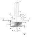
- Fig. 1 shows a section of a section through a casting model 1 with a model surface 2.
- a recess 3 is inserted, which also has a pot-shaped shape. At its lower end, the recess 3 continues into a guide 4.
- the guide 4 is centered on the longitudinal axis 5.
- a spring receptacle 6 is inserted, which has a pot-shaped shape and rests against the wall of the recess 3.
- the spring seat 6 continues into a spring travel bushing 7.
- Spring receptacle 6 and spring travel bushing 7 may be made of a suitable material, such as steel or plastic.
- a coil spring 8 is used, which is supported with its fixed end 9 at the bottom of the spring seat 6.
- a foot 11 is supported on which centrally along the longitudinal axis 5, a receiving mandrel 12 is arranged.
- the foot 11 has a cross section which corresponds approximately to the cross section of the spring seat 6.
- a sliding seal 13 is provided, which prevents penetration of sand into the gap between the foot 11 and the spring seat 6. The seal slides during the axial displacement of the foot along the side surfaces 30 of the spring retainer.
- a guide pin 14 is provided, which is arranged centrally along the longitudinal axis 5.
- the guide pin 14 has a circular cross section and is slidably received in the spring travel bushing 7.
- Guide pin 14 and spring travel bushing 7 have approximately the same cross section, so that the wall of the guide pin 14 is guided along the wall of the spring path bushing 7 with an axial displacement.
- the foot 11 has on its side facing away from the coil spring 8 side 31 a circumferential inclined surface 15, which forms a lower peripheral edge 16 at its lower end.
- the circumferential inclined surface 15 is bounded by a circumferential edge 17.
- the peripheral edge 17 has a smaller radius than the peripheral edge 16. From the peripheral edge 17, an annular footprint 18 is limited, which is positioned perpendicular to the longitudinal axis 5. The inner side of the footprint is bounded by the mandrel 12.
- the foot 11 has an extension in the direction of the longitudinal axis 5, so that it in the in Fig. 1 shown position with a portion 19 is received in the spring seat 6.
- This guide is reinforced by the guide pin 14 in the in Fig. 1 shown position engages the spring travel socket 7.
- the foot 11 protrudes with a portion 20 on the model surface 2.
- Fig. 1 shown position corresponds to a first rest position of the spring mandrel.
- the mandrel 12 terminates in a tip 21, which serves to center a feeder, which can be placed on the mandrel.
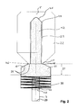
- Fig. 2 corresponds essentially to the presentation Fig.
- the feeder 22 has a feeder cavity 23.
- the tip 21 of the spring mandrel 12 abuts a corresponding inclined surface 24 at the upper end of the feeder cavity 23, whereby feeder 22 is centered along the longitudinal axis 5.
- the feeder 22 stands with its lower footprint 25 on the footprint 18 of the foot 11.
- the feeder 22 forms, together with the circumferential inclined surface 15, a breaking edge 26.
- Fig. 2 For example, the position of the mandrel with the attached feeder is shown in a state prior to the compaction of the molding material, which is applied to the model surface 2 and surrounds the feeder 22.
- the feeder When compacting the molding material, the feeder is moved in the direction of the longitudinal axis 5 on the model surface 2. He puts it a spring 27 back. The spring travel is limited by the fact that the guide pin 14 comes with its stop surface 28 on the stop surface 29 of the spring path bushing 7 to the plant.
- the mold is removed from the casting model, wherein the mandrel 12 is pulled out of the feeder cavity 23.
Landscapes
- Engineering & Computer Science (AREA)
- Mechanical Engineering (AREA)
- Molds, Cores, And Manufacturing Methods Thereof (AREA)
Applications Claiming Priority (1)
| Application Number | Priority Date | Filing Date | Title |
|---|---|---|---|
| DE201010022834 DE102010022834B4 (de) | 2010-06-07 | 2010-06-07 | Federdorn und Gießmodell mit Federdorn |
Publications (1)
| Publication Number | Publication Date |
|---|---|
| EP2392425A2 true EP2392425A2 (fr) | 2011-12-07 |
Family
ID=44652062
Family Applications (1)
| Application Number | Title | Priority Date | Filing Date |
|---|---|---|---|
| EP20110004527 Withdrawn EP2392425A2 (fr) | 2010-06-07 | 2011-06-03 | Broche et modèle de moulage avec une broche |
Country Status (2)
| Country | Link |
|---|---|
| EP (1) | EP2392425A2 (fr) |
| DE (1) | DE102010022834B4 (fr) |
Cited By (1)
| Publication number | Priority date | Publication date | Assignee | Title |
|---|---|---|---|---|
| CN110369679A (zh) * | 2019-08-26 | 2019-10-25 | 共享装备股份有限公司 | 冒口定位卡 |
Families Citing this family (1)
| Publication number | Priority date | Publication date | Assignee | Title |
|---|---|---|---|---|
| WO2017072004A1 (fr) | 2015-10-27 | 2017-05-04 | Gtp Schäfer Giesstechnische Produkte Gmbh | Mandrin de formage doté d'une enveloppe pouvant être élargie et modèle de coulée doté d'un mandrin de formage ainsi que procédé de coulée de métaux |
Citations (4)
| Publication number | Priority date | Publication date | Assignee | Title |
|---|---|---|---|---|
| DE4119112A1 (de) | 1990-06-28 | 1992-03-12 | Niesky Waggonbau Gmbh | Horizontaldaempfung an laufwerken von eisenbahngueterwagen |
| DE19503456C1 (de) | 1995-02-03 | 1995-11-02 | Daimler Benz Ag | Anordnung aus einem topfförmigen Speiser und einem diesen mit Abstand auf einem Gießmodell lagernden Dorn |
| DE10142357A1 (de) | 2001-08-30 | 2003-03-27 | Luengen Gmbh & Co Kg As | Speiser mit einem rohrähnlichen Körper |
| WO2005095020A2 (fr) | 2004-03-31 | 2005-10-13 | AS Lüngen GmbH & Co. KG | Masselotte a manchon deformable |
Family Cites Families (1)
| Publication number | Priority date | Publication date | Assignee | Title |
|---|---|---|---|---|
| DE4119192A1 (de) | 1991-06-11 | 1992-12-17 | Hoesch Ag | Federnder dorn zum halten von speisern |
-
2010
- 2010-06-07 DE DE201010022834 patent/DE102010022834B4/de not_active Expired - Fee Related
-
2011
- 2011-06-03 EP EP20110004527 patent/EP2392425A2/fr not_active Withdrawn
Patent Citations (4)
| Publication number | Priority date | Publication date | Assignee | Title |
|---|---|---|---|---|
| DE4119112A1 (de) | 1990-06-28 | 1992-03-12 | Niesky Waggonbau Gmbh | Horizontaldaempfung an laufwerken von eisenbahngueterwagen |
| DE19503456C1 (de) | 1995-02-03 | 1995-11-02 | Daimler Benz Ag | Anordnung aus einem topfförmigen Speiser und einem diesen mit Abstand auf einem Gießmodell lagernden Dorn |
| DE10142357A1 (de) | 2001-08-30 | 2003-03-27 | Luengen Gmbh & Co Kg As | Speiser mit einem rohrähnlichen Körper |
| WO2005095020A2 (fr) | 2004-03-31 | 2005-10-13 | AS Lüngen GmbH & Co. KG | Masselotte a manchon deformable |
Cited By (1)
| Publication number | Priority date | Publication date | Assignee | Title |
|---|---|---|---|---|
| CN110369679A (zh) * | 2019-08-26 | 2019-10-25 | 共享装备股份有限公司 | 冒口定位卡 |
Also Published As
| Publication number | Publication date |
|---|---|
| DE102010022834A1 (de) | 2012-03-29 |
| DE102010022834B4 (de) | 2012-05-31 |
Similar Documents
| Publication | Publication Date | Title |
|---|---|---|
| DE10039519B4 (de) | Speisereinsatz | |
| EP2097193B1 (fr) | Insert d'alimenteur et élément alimenteur | |
| EP1345716B2 (fr) | Masselotte presentant un corps tubulaire | |
| EP2982458B1 (fr) | Systeme a utiliser lors de la production d'un moule divisible | |
| EP1732719B1 (fr) | Masselotte a manchon deformable | |
| DE4021591C2 (fr) | ||
| DE202013001933U1 (de) | Speisereinsatz | |
| DE102010022834B4 (de) | Federdorn und Gießmodell mit Federdorn | |
| EP2956256B1 (fr) | Insert de dispositif d'alimentation et procédé permettant d'agencer ledit insert dans un moule | |
| EP3075504B1 (fr) | Dispositif de fabrication d'éléments de formage en béton dans une machine à mouler | |
| EP3075505B1 (fr) | Dispositif de fabrication d'éléments de formage en béton | |
| DE10142357B4 (de) | Speiser mit einem rohrähnlichen Körper | |
| EP3727723A1 (fr) | Procédé de production d'une partie de moule ainsi qu'insert d'alimentation destiné à être utilisé dans un tel procédé | |
| EP1728570B1 (fr) | Masselotte avec un bas sous | |
| EP4297920B1 (fr) | Dispositif d'alimentation divisé verticalement destiné à être utilisé lors de la coulée de métaux dans des moules de coulée, et son procédé de production | |
| DE102007061155A1 (de) | Speiser | |
| DE10059481B4 (de) | Speiser mit einem rohrähnlichen Körper | |
| EP3368234B1 (fr) | Mandrin de formage doté d'une enveloppe pouvant être élargie et modèle de coulée doté d'un mandrin de formage ainsi que procédé de coulée de métaux | |
| DE20122062U1 (de) | Speisereinsatz | |
| EP1779944B1 (fr) | Masselotte avec bouchon pour fermer sa entrée | |
| DE102020122072A1 (de) | Transponderkappe | |
| DD229052B1 (de) | Halterung fuer hohlraumbildende formkoerper und eingusselemente |
Legal Events
| Date | Code | Title | Description |
|---|---|---|---|
| AK | Designated contracting states |
Kind code of ref document: A2 Designated state(s): AL AT BE BG CH CY CZ DE DK EE ES FI FR GB GR HR HU IE IS IT LI LT LU LV MC MK MT NL NO PL PT RO RS SE SI SK SM TR |
|
| AX | Request for extension of the european patent |
Extension state: BA ME |
|
| PUAI | Public reference made under article 153(3) epc to a published international application that has entered the european phase |
Free format text: ORIGINAL CODE: 0009012 |
|
| STAA | Information on the status of an ep patent application or granted ep patent |
Free format text: STATUS: THE APPLICATION HAS BEEN PUBLISHED |
|
| STAA | Information on the status of an ep patent application or granted ep patent |
Free format text: STATUS: THE APPLICATION IS DEEMED TO BE WITHDRAWN |
|
| 18D | Application deemed to be withdrawn |
Effective date: 20170103 |