EP2392425A2 - Spring mandrel and casting pattern with same - Google Patents
Spring mandrel and casting pattern with same Download PDFInfo
- Publication number
- EP2392425A2 EP2392425A2 EP20110004527 EP11004527A EP2392425A2 EP 2392425 A2 EP2392425 A2 EP 2392425A2 EP 20110004527 EP20110004527 EP 20110004527 EP 11004527 A EP11004527 A EP 11004527A EP 2392425 A2 EP2392425 A2 EP 2392425A2
- Authority
- EP
- European Patent Office
- Prior art keywords
- spring
- foot
- mandrel
- casting
- receptacle
- Prior art date
- Legal status (The legal status is an assumption and is not a legal conclusion. Google has not performed a legal analysis and makes no representation as to the accuracy of the status listed.)
- Withdrawn
Links
Images
Classifications
-
- B—PERFORMING OPERATIONS; TRANSPORTING
- B22—CASTING; POWDER METALLURGY
- B22C—FOUNDRY MOULDING
- B22C9/00—Moulds or cores; Moulding processes
- B22C9/08—Features with respect to supply of molten metal, e.g. ingates, circular gates, skim gates
- B22C9/088—Feeder heads
Definitions
- the invention relates to a spring mandrel for insertion into a casting model for the production of casting molds and a casting model for the production of molds, with a substantially perpendicular to the surface of the casting model movable receiving mandrel for receiving a feeder.
- liquid metal is poured into a mold having a casting cavity.
- the casting cavity substantially corresponds to the negative shape of the workpiece to be produced.
- the mold comprises supply lines through which the liquid metal can be introduced into the casting cavity, and cavities, so-called feeders, which serve as surge tanks to compensate for the volume loss that occurs during the solidification of the metal and thus counteract a voids formation in the casting.
- the feeders are connected to the casting or to the vulnerable casting area and are usually arranged above or on the side of the casting cavity. After solidification of the metal remain in the feeder cavities and in the leads still metal residues that must be removed from the workpiece. In this case, it is endeavored to keep the size of these metal residues as low as possible and to design their shape so that these residues can be removed as easily and completely as possible, for example by knocking off.
- a casting model is initially provided whose contour substantially corresponds to the inner contour of the casting cavity.
- This casting model is also referred to as a model plate.
- the mold can be composed of several pieces. Accordingly, it is therefore possible that the casting model depicts only a portion of the casting.
- a holding device is usually provided on the casting model, for example a mandrel for fixing the position of the feeder or the supply line.
- a molding material as a rule molding sand, is applied to the casting model so that the feeder and the feed line are enveloped by the molding material.
- the molding material is then compressed, so that feeders and supply lines of compressed molding material are enclosed.
- Spring arbors typically include a tubular member for attachment to the casting model, a spring disposed within the tubular member, and a mandrel tip member resting on the spring and telescopically slidable in the axial direction.
- a feeder is attached to the spring mandrel. By the spring mandrel, the lower end of the feeder is kept at a distance from the surface of the casting model.
- the feeder is moved against the spring force exerted by the spring mandrel in the direction of the surface of the casting model, without the bottom of the feeder comes directly in contact with the model surface. Destruction of the feeder insert is therefore prevented even when using high compression forces.
- the feeder consists of a holding and guide part, which can be attached via a threaded pin on the model.
- a spring is placed over which a cup-shaped shell is placed, so that the jacket surrounds the spring and the upper part of the holding and guiding part, wherein the pot opening is directed downward in the direction of the model.
- the jacket can be moved in the axial direction, wherein the displacement is guided by the holding and guiding part.
- Another way to absorb the compression forces occurring during compaction of the molding sand is to provide a break point in the feeder, wherein the feeder is transferred after fracture of the fracture from a first, further spaced from the model position in a second, lying closer to the model position.
- a first and a second rigidly predetermined stop for a first and a second distance position of the feeder are specified on the mandrel.
- the surface of the casting model near distance position of the feeder passes during compaction of the molding sand by a predetermined breaking point opens in the bottom of the feeder by the counterpressure from the mandrel, whereby the feeder can go into the second distance position.
- a tube-like body which connects the cavity of the feeder with the model or in the finished mold with the cavity of the mold.
- the tube-like body has the shape of a hollow cylinder, which tapers at the end facing the casting.
- the feeder moves toward the surface of the model, displacing the feeder along the outer surface of the tubular body so as to displace the tubular body into the feeder cavity.
- the breaking edge forms controlled in the immediate vicinity of the casting cavity, so that after casting, a residual feeder remaining on the casting can be checked off in a controlled manner, without any substantial reworking of the surface of the casting is required.
- the feeder has a deformable spout, which is supported with its upper end on the underside of the feeder.
- the feeder with the deformable grommet mounted therein is slipped over a spring mandrel attached to the model.
- the deformable grommet then stands directly on the model or on the foot of the spring thorn.
- the deformable spout tapers in the direction of the model so that a breaking edge is formed.
- the feeder again moves in the direction of the model.
- the deformable spout deforms which may include, for example, a concertina-shaped element.
- the lower end of the nozzle is not displaced so that a breaking edge is formed in the immediate vicinity of the model or the casting. Even with the use of this type of feeder, therefore, it is very easy to cut off a residual feeder remaining on the casting after casting, resulting in a fracture surface which does not require any substantial post-processing.
- refractive cores are used. These are disk-shaped bodies which have a passage opening which is narrower than the opening of the feeder.
- the refractive cores are placed directly on the model and the feeders are arranged on the breaker core.
- the feeder must therefore be made very stable, which, as explained above, an increased cost of materials and thus increased costs entails.
- the break core can also be attached to the feeder, for example with an adhesive bond.
- the feeder can then be attached to the model by means of a spring pin.
- the invention therefore an object of the invention to provide a spring mandrel for use in a casting model for the production of molds, which can be used universally for all types of feeders, with all feeders destruction during compression of the molding material to be avoided.
- a foot is provided, which is provided with a receiving mandrel on which a feeder can be placed.
- the foot is arranged on a spring.
- the feeder can therefore be displaced in the axial direction, so that the reduction of the volume of the molding material occurring during compacting of the molding material and the force thereby acting on the feeder can be absorbed by an axial displacement of the feeder on the casting model.
- the spring is received in a spring receiver, which can be integrated into the casting model.
- the upper side of the foot or the underside of a plugged-on mandrel on the mandrel is positioned in the vicinity of the top of the casting model, so that a precise positioning of the feeder is possible.
- all types of feeders can be plugged, so both simple pot-shaped feeders, optionally in combination with a breaker core, tubular riser sleeves and more complex constructed feeder, such as the feeder described above with a tubular body or with a deformable spout.
- the invention is therefore a spring mandrel for insertion into a casting model for the production of molds, with an insertable into the mold model spring receptacle, which is designed so that it can be fully integrated into the casting model, a spring inserted into the spring receiving, which with its fixed end is supported on the spring receptacle, a foot supported on a free end of the spring, which is received at least in sections in the spring receptacle and displaceable therein, and a receptacle arranged on the receptacle for receiving a feeder.
- the spring receptacle of the spring mandrel according to the invention can be made of any material per se, for example made of plastic or steel sheet. It can be secured with a suitable fastener, such as screws, such as set screws, in a corresponding recess of the casting model.
- the spring receptacle can also be formed directly through a recess in the casting model.
- a spring is added.
- a coil spring is used, which is made of a suitable spring steel.
- the diameter of the spring is preferably chosen so that it fills the cross section of the spring receptacle. But it is also possible to use springs with a smaller cross-section.
- the spring is supported by one end on the spring receiver.
- the spring can also be attached to the spring receiver. But it is also possible to simply insert the spring in the spring receiver.
- the end, with which the spring is supported on the spring seat, is referred to as a fixed end, since it performs no relative movement to the casting model during the compression of the molding material.
- On the free, movable end of the spring of the foot of the mandrel is placed, which is supported at the free end of the spring.
- the foot is slidably mounted in the spring receiving, so that the foot against the force of the spring can perform an axial movement in the direction of the casting model.
- a mandrel On the side of the foot, which is the side opposite, with which the foot is supported on the spring, a mandrel is provided, with which a feeder can be centered on the foot.
- Suitable materials for foot and mandrel are, for example, metal, plastic, or wood.
- Mandrel and foot can be made in one piece. But it is also possible to make foot and mandrel separately and then connect them together.
- the receiving mandrel is preferably arranged centrally on the foot, so that a feeder, which is placed over the receiving dome, is arranged centrally on the foot.
- the locating mandrel may be provided with a centering device, through which a feeder that is slipped over the locating mandrel is centered.
- the arbor can leak at its upper end in a tip, which can come to rest on a correspondingly shaped mating surface of the feeder, so that the feeder is centered.
- the foot of the feeder, as well as the spring receptacle and the mandrel, preferably have a circular cross-section. This facilitates the positioning of the feeder, as feeders generally also have a circular cross-section.
- the peculiarity of the spring mandrel according to the invention is that the spring is not arranged in the body of the mandrel, but is received below the mandrel in a spring receptacle.
- the spring retainer is designed so that it can be fully integrated into the casting model. When installed, the spring receptacle in the spring mandrel according to the invention is thus arranged below the surface of the casting model. It is therefore much more space for the spring and the spring receptacle available, which is why the spring and the spring receptacle can be made much more robust. Larger and more stable springs can be used, and the spring retainer is much less susceptible to penetrating sand because of the significantly larger available tolerances compared to the previously used spring spikes.
- spring pins are very sensitive to penetrating sand, so that such spring pins wear relatively quickly and, for example, block when sand penetrates into the gap between the stationary and movable portion of the spring mandrel. This is a hindrance especially in automated production.
- the spring pin according to the invention is much more robust and tolerates penetration of molding sand into the spring receptacle to a much greater extent, without blocking the axial movement of the spring mandrel occurs.
- the spring receptacle can be completely integrated into a casting model.
- “fully integrated” is meant that all essential parts of the spring retainer are located below the surface of the casting model.
- Above the surface of the casting model so at best fastening elements for the spring receiving are arranged, such as tabs or a circumferential ring, which are arranged projecting from the body of the spring receptacle at the upper, open end of the spring receiving along its circumference.
- the spring receptacle is configured so that no parts are arranged above the surface of the casting model.
- the spring receptacle preferably has a cup-shaped shape. The spring inserted in the spring receiver then rests on the bottom of the pot. In other words, the free spring travel does not extend beyond the surface of the casting model.
- the spring receiver When producing a casting mold, first the spring receiver is attached to the casting model. For this purpose, corresponding, preferably circular, recesses or openings are provided on the casting model, into which the spring receptacle is inserted. This is then, as already described above, fastened by means of screws, for example, on the casting model. After the spring is inserted into the spring retainer, the foot can be used with the mounting arbor attached to the spring receptacle. But it is also possible that spring receptacle, spring and the foot are pre-assembled with mandrel provided and the pre-assembled spring mandrel is inserted into the recess provided in the casting model or opening and fastened there. This attachment can be done for example by means of springs, claws, clamps, or, as described above, also by a screw connection. Other attachment means, such as an adhesive bond, are also possible.
- the spring is preferably dimensioned to have a spring constant such that a feeder mounted on the foot with the mandrel is held in a spaced position from the surface of the casting mold.
- the foot is partially inserted into the spring retainer, so that a guide is achieved when the foot slides with its outer peripheral surface at an axial displacement along the wall of the spring retainer.
- molding sand or other suitable molding material is then abandoned and this then compacted in the usual way. In this case, moves through the pressure acting upon compression of the foot and thus also the feeder in the direction of the casting model, wherein the foot is moved further into the spring receiving into it.
- the foot can already be guided by the spring seat in the axial displacement.
- at least one guide can be provided, through which the displacement of the foot is guided in the spring receiver.
- the guide can be done by various devices.
- a guide rod can be provided in the spring receptacle in the axial direction, which is accommodated in a corresponding bore of the foot or of the receiving mandrel so that the foot or the receiving mandrel is guided along the guide pin during an axial displacement.
- It may be provided a central guide pin.
- a plurality of pins which may be arranged outside the longitudinal axis of the receiving mandrel in the spring receiving.
- It is also possible to provide on the circumference of the foot one or more grooves extending parallel to the longitudinal axis, in which corresponding, preferably strip-shaped projections engage on the lateral surfaces of the spring receptacle.
- the grooves slide during the axial displacement of the feeder then along the projections provided in the spring receiving, whereby a stabilization of the axial displacement is achieved. It is also possible to provide the grooves in the side wall of the spring retainer and the strip-shaped projections on the peripheral surface of the foot.
- the guide is formed as a guide extension, which is arranged on the side of the foot on which the foot is supported on the spring, wherein the guide extension is received in a receptacle in which the guide extension is guided.
- the guide extension is preferably designed as a cylindrical body which is centrally located centrally on the underside of the foot. This guide extension is received in a correspondingly shaped spring path bushing, into which the guide extension is pushed during the compaction of the molding material. It can be provided on the underside of the foot more of these guide projections, each of which engage in a guide extension associated with the receptacle. Preferably, however, is provided to provide only a guide extension, which is arranged centrally on the underside of the foot and engages in a subsequent to the spring receiving centrally arranged spring travel bushing.
- Foot and mandrel may have the same diameter per se.
- the feeder would be held in a position by the end face of the take-up mandrel.
- the receiving mandrel has a smaller diameter than the foot. This makes it possible for the feeder, with its lower end face, to stand up on a surface of the foot, and therefore a precise positioning of the feeder relative to the surface of the casting model is possible.
- the feeder can stand up on the foot of the mandrel, the forces acting on the feeder in compressing the molding material in the axial direction forces are transmitted via the footprint of the feeder in the foot of the mandrel and from there into the spring. As a result, the risk that the feeder breaks when compressing the molding material, compared to the known spring mandrels significantly reduced.
- the path of the axial displacement of the receiving mandrel is limited.
- the spring travel is limited by the guide with axial displacement of the foot and the spring mandrel, ie in the direction of the longitudinal axis, so that the foot in an inserted position preferably with an upper edge running around its upper circumference approximately to the upper Completion of the spring receptacle completes.
- the guide extension and the guide extension leading recording be dimensioned so that the guide extension comes to rest on a boundary surface of the receptacle when the foot is inserted to the desired end position in the spring retainer.
- the guide extension and the guide extension leading recording be dimensioned so that the guide extension comes to rest on a boundary surface of the receptacle when the foot is inserted to the desired end position in the spring retainer.
- arranged on the underside of the foot designed as a cylindrical bolt guide extension with its lower end face on an end face of the spring path bushing come to rest, so that no further displacement of the foot in the axial direction is more possible.
- an edge is indicated which runs around the outer circumference of the foot, for example in the form of a circle, the circumference corresponding to the circumference of the surface with which the foot moves axially along the side surface of the foot Spring retainer slides.
- the circumference has, for example, in the case of a circular cross-section of the foot the same radius as the foot at its widest point.
- This edge extends in the axial direction spaced from the edge of the surface on which the spring rests on the foot. If, for example, the foot has the shape of a cylindrical disk, then the foot has a constant diameter in the axial direction, corresponding to the upper edge of the upper edge of the foot surrounding the upper circumference.
- the foot on the side opposite the spring on a tapered circumferential surface to form a breaking edge can be chosen arbitrarily.
- the inclined surface has an inclination in the range of 30 to 60 ° to the longitudinal axis of the foot or the mandrel.
- the upper peripheral edge of the foot around the upper circumference may correspond to the peripheral edge around the outer circumference.
- the tapered surface may, if desired, in cooperation with a corresponding surface of the feeder, produce a wedge-shaped constriction around the feeder foot. By compaction of the sand, a breaking edge forms, which allows a controlled knocking off of the residual feeder.
- the spring dome according to the invention is relatively insensitive to penetrating sand.
- the diameter of the foot is preferably selected so that it approximately corresponds to the diameter of the spring receptacle, so that only a narrow gap between the foot and spring receptacle is formed.
- the width of the gap is preferably chosen to be less than 1 mm, preferably less than 0.5 mm.
- the foot is guided at least partially free of play in the spring retainer.
- a seal is provided between the foot and the spring receptacle, by means of which an ingress of molding sand into the spring receptacle is prevented by a gap which forms between the foot and the spring receptacle.
- This seal is preferably designed as a sliding seal.
- the seal can be attached to both the spring retainer so that the foot, when axially displaced, slides with its outer peripheral surface over the seal. But it is also possible to provide the seal at the foot of the mandrel. The seal then slides during the axial displacement of the foot along the side surfaces of the spring retainer.
- the length of the mandrel is chosen depending on the feeder used.
- the mandrel does not necessarily have to extend over the entire length of the interior of a feeder, which is placed on the mandrel. Rather, it may be sufficient that the receiving mandrel is designed in the form of a stub and centers the feeder only by a contact on the opening of the feeder and thus holds in position.
- the receiving dome in its length in the direction of the longitudinal axis. This allows the length of the mandrel to be adapted to the length of the cavity of the feeder used.
- the spring mandrel according to the invention is installed or integrated with its spring receiver directly into the casting model. As a result, the spring mandrel can be made more robust and thus less sensitive to penetrating sand compared to known spring mandrels.
- Another object of the invention therefore relates to a casting model for the production of casting molds with a vertically displaceable to the surface of the casting model mandrel for receiving a feeder, wherein a compressible element, in particular a spring element, is provided which damps the displacement of the mandrel.
- a compressible element in particular a spring element
- the compressible element or the spring element is at least partially integrated into the casting model.
- a recess is provided in the casting model at the location at which the mandrel or the riser is to be positioned, which can serve directly as a spring receptacle or in which a spring receptacle formed, for example, from sheet metal, plastic or another suitable material can be included.
- a spring receiver can be fastened to the casting model, for example, by means of a screw or another suitable fastening means.
- a foot is placed with a receiving mandrel arranged thereon.
- the spring constant and the extent of the spring is selected such that a feeder placed on the mandrel is kept at a distance from the surface of the casting model in a rest position, ie a position before the task and compaction of the molding material.
- a rest position ie a position before the task and compaction of the molding material.
- the foot of the mandrel is partially received in the spring receptacle, so that the foot may possibly slide with the outer periphery during insertion of the mandrel along the wall of the spring retainer.
- the spring element is integrated into the casting model.
- the spring element is arranged substantially below the surface of the casting model and, independently of this, preferably terminates with the surface of the casting model.
- the spring element is designed so that it comprises an integrated into the casting model spring receptacle and a spring received in the spring receiving.
- the spring receptacle is preferably a cup-shaped vessel, which is made for example of sheet metal, plastic or other suitable material.
- At the spring receiving fastening means may be provided, with which the spring receptacle is received in a corresponding receptacle, which is provided on the casting model.
- Such a receptacle can be, for example, a recess which, for example, has a pot-shaped form and is matched in its dimensions to the spring receptacle. It is also possible, for example, that a corresponding opening is provided on the model into which the spring receiver is inserted.
- an opening in the spring receptacle may be provided, through which a screw is inserted to secure the spring receptacle in the recess or opening provided in the casting model.
- suitable fastening means such as springs, clamps, claws or even an adhesive connection, are also possible.
- a spring is added in the spring receptacle. This is preferably designed as a spiral spring.
- the dimensioning and the spring constant of the spring is dependent on the size or weight of the feeder, which is to be installed in the mold.
- the spring should be designed so that in a state prior to the compaction of the molding material, the feeder is arranged closely spaced from the surface of the casting model.
- the spring receptacle may for example be formed as a plate which is arranged at the bottom of a recess which is mounted in the casting model. The side walls of the recess can then act as a guide for the spring.
- the spring receptacle preferably has a pot-shaped form, wherein it is provided that the spring receptacle terminates in an inserted state with the surface of the casting model. The spring holder can then be very easily inserted into a corresponding receptacle of the casting model and adjust in this.
- the mandrel has a foot, wherein the foot is slidably mounted in the spring receptacle and is supported on the spring received in the spring receptacle.
- the foot preferably has approximately the same diameter or circumference as the spring retainer so that the foot can be displaced along the wall of the spring retainer and thereby experience guidance.
- the feeder is slipped over the mandrel and then preferably rests on a surface of the foot.
- the mandrel is preferably located in a central position on the upper side of the foot so that the feeder is automatically centered.
- the extent of the foot in the axial direction is preferably chosen so that the foot is in the rest position, i. with attached feeder, but before task and compaction of the molding material, is partially absorbed in the spring receptacle. So the foot partially protrudes from the spring receiver.
- the distance between the top of the foot and the surface of the casting model preferably corresponds at least to the spring travel, which the foot completes during the compaction of the molding material.
- the breaking edge is preferably arranged so that the feeder has only a small footprint on the foot of the spring mandrel.
- the footprint of the feeder is selected to be less than 50%, preferably less than 40%, more preferably less than 30%, and more preferably less than 20% of the cross-sectional area of the foot of the mandrel.
- the cross-sectional area is understood to be the area defined by the maximum circumference of the esophagus foot.
- the footprint of the feeder on the foot preferably at least 5%, more preferably at least 10% of the cross-sectional area of the foot of the mandrel.
- the contact surface of the feeder is understood to be the preferably annular surface on the surface of the foot, which is formed between the upper edge of the inclined surface, if present, and the lower end of the receiving mandrel.
- the foot on its side opposite the mandrel has a guide extension through which the displacement of the mandrel is performed.
- the guide extension preferably has a circular cross-section. It is possible to provide multiple guide extensions. For manufacturing reasons, however, it is preferable to provide only one guide extension. This guide extension is then preferably arranged axially on the underside of the foot of the receiving mandrel. The guide extension is received in a guided in the casting model or provided on the spring receiving guide through which the axial movement of the mandrel is performed.
- the guide extension limits the displacement of the spring mandrel, so that the foot in its inserted position terminates with its upper peripheral edge with the surface of the casting model.
- the crushing edge is positioned near the surface of the casting so that a residual feeder can be removed after casting by knocking and little or no brushing is required to bring the surface of the casting into the desired shape.
- an upper peripheral edge is meant the edge on the outer circumference of the foot, which is arranged in a remote position to the contact surface of the spring. If an inclined surface is provided for forming a breaking edge, the upper peripheral edge of the foot corresponds to the edge formed by the inclined surface on the outer circumference of the foot, that is to say the lower edge of the inclined surface.
- the inclined surface has an inclination of at least 10 °, preferably at least 20 °, more preferably at least 30 °, relative to the upper side of the feeder foot (or relative to the model surface.)
- the inclination of the inclined surface is less than 60 °, preferably less than 50 °, in particular less than 40 °.
- the travel of the mandrel is preferably chosen so that in an inserted state of the spring mandrel, so after compaction of the molding material, the upper peripheral edge of the foot with the surface of the casting model is completed or arranged at a small distance to this, preferably at a distance of less than 5 mm, more preferably less than 4 mm, more preferably less than 3 mm.
- the upper peripheral edge of the foot is arranged in the retracted position below the surface of the casting model, since in this case a corresponding recess is formed on the casting.
- a receiving mandrel is provided on the casting model, which is formed by a spring mandrel, as has been described above.
- the invention relates to a method for producing a casting mold for metal casting.
- a casting model is initially provided which has at least one recess for receiving a spring mandrel, as described above.
- the casting model approximately corresponds to the shape of the casting to be made with the casting mold, taking into account, for example, shrinkage of the casting upon cooling of the metal after casting.
- the casting mold may be a section of a casting mold.
- the mold may correspond to a mold or a core.
- a spring mandrel is used, as has been described above.
- a feeder is placed on the receiving mandrel provided on the mandrel.
- conventional feeders can be used. There are no special restrictions.
- a molding material is then abandoned in the usual way. It can be used conventional molding materials.
- a suitable molding material is for example quartz sand, which is mixed with a suitable binder.
- the molding material is then compacted in the usual way, whereby a casting mold is obtained. Finally, the mold is removed from the casting model. Depending on the molding material used, the mold can still be cured. This can be done before the mold is removed from the casting model. When using a corresponding molding material, but it is also possible that the mold is cured after the removal of the casting model.
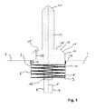
- Fig. 1 shows a section of a section through a casting model 1 with a model surface 2.
- a recess 3 is inserted, which also has a pot-shaped shape. At its lower end, the recess 3 continues into a guide 4.
- the guide 4 is centered on the longitudinal axis 5.
- a spring receptacle 6 is inserted, which has a pot-shaped shape and rests against the wall of the recess 3.
- the spring seat 6 continues into a spring travel bushing 7.
- Spring receptacle 6 and spring travel bushing 7 may be made of a suitable material, such as steel or plastic.
- a coil spring 8 is used, which is supported with its fixed end 9 at the bottom of the spring seat 6.
- a foot 11 is supported on which centrally along the longitudinal axis 5, a receiving mandrel 12 is arranged.
- the foot 11 has a cross section which corresponds approximately to the cross section of the spring seat 6.
- a sliding seal 13 is provided, which prevents penetration of sand into the gap between the foot 11 and the spring seat 6. The seal slides during the axial displacement of the foot along the side surfaces 30 of the spring retainer.
- a guide pin 14 is provided, which is arranged centrally along the longitudinal axis 5.
- the guide pin 14 has a circular cross section and is slidably received in the spring travel bushing 7.
- Guide pin 14 and spring travel bushing 7 have approximately the same cross section, so that the wall of the guide pin 14 is guided along the wall of the spring path bushing 7 with an axial displacement.
- the foot 11 has on its side facing away from the coil spring 8 side 31 a circumferential inclined surface 15, which forms a lower peripheral edge 16 at its lower end.
- the circumferential inclined surface 15 is bounded by a circumferential edge 17.
- the peripheral edge 17 has a smaller radius than the peripheral edge 16. From the peripheral edge 17, an annular footprint 18 is limited, which is positioned perpendicular to the longitudinal axis 5. The inner side of the footprint is bounded by the mandrel 12.
- the foot 11 has an extension in the direction of the longitudinal axis 5, so that it in the in Fig. 1 shown position with a portion 19 is received in the spring seat 6.
- This guide is reinforced by the guide pin 14 in the in Fig. 1 shown position engages the spring travel socket 7.
- the foot 11 protrudes with a portion 20 on the model surface 2.
- Fig. 1 shown position corresponds to a first rest position of the spring mandrel.
- the mandrel 12 terminates in a tip 21, which serves to center a feeder, which can be placed on the mandrel.
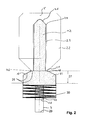
- Fig. 2 corresponds essentially to the presentation Fig.
- the feeder 22 has a feeder cavity 23.
- the tip 21 of the spring mandrel 12 abuts a corresponding inclined surface 24 at the upper end of the feeder cavity 23, whereby feeder 22 is centered along the longitudinal axis 5.
- the feeder 22 stands with its lower footprint 25 on the footprint 18 of the foot 11.
- the feeder 22 forms, together with the circumferential inclined surface 15, a breaking edge 26.
- Fig. 2 For example, the position of the mandrel with the attached feeder is shown in a state prior to the compaction of the molding material, which is applied to the model surface 2 and surrounds the feeder 22.
- the feeder When compacting the molding material, the feeder is moved in the direction of the longitudinal axis 5 on the model surface 2. He puts it a spring 27 back. The spring travel is limited by the fact that the guide pin 14 comes with its stop surface 28 on the stop surface 29 of the spring path bushing 7 to the plant.
- the mold is removed from the casting model, wherein the mandrel 12 is pulled out of the feeder cavity 23.
Landscapes
- Engineering & Computer Science (AREA)
- Mechanical Engineering (AREA)
- Molds, Cores, And Manufacturing Methods Thereof (AREA)
Abstract
Description
Die Erfindung betrifft einen Federdorn zum Einsetzen in ein Gießmodell für die Herstellung von Gießformen sowie ein Gießmodell für die Herstellung von Gießformen, mit einem im Wesentlichen senkrecht zur Oberfläche des Gießmodells verschiebbaren Aufnahmedorn für die Aufnahme eines Speisers.The invention relates to a spring mandrel for insertion into a casting model for the production of casting molds and a casting model for the production of molds, with a substantially perpendicular to the surface of the casting model movable receiving mandrel for receiving a feeder.
Bei der Herstellung von Werkstücken in der Gießerei wird flüssiges Metall in eine Gießform eingefüllt, welche einen Gießhohlraum aufweist. Der Gießhohlraum entspricht im Wesentlichen der Negativform des herzustellenden Werkstücks. Ferner umfasst die Gießform Zuleitungen, durch welche das flüssige Metall in den Gießhohlraum eingeleitet werden kann, sowie Hohlräume, sogenannte Speiser, die als Ausgleichsbehälter dienen, um den Volumenverlust, der beim Erstarren des Metalls eintritt, auszugleichen und so einer Lunkerbildung im Gussstück entgegenzuwirken. Dazu sind die Speiser mit dem Gussstück bzw. mit dem gefährdeten Gussstückbereich verbunden und gewöhnlich oberhalb bzw. an der Seite des Gießhohlraums angeordnet. Nach dem Erstarren des Metalls verbleiben in den Speiserhohlräumen sowie in den Zuleitungen noch Metallreste, die vom Werkstück entfernt werden müssen. Dabei ist man bemüht, die Größe dieser Metallreste möglichst gering zu halten und deren Form so auszugestalten, dass sich diese Reste beispielsweise durch Abschlagen möglichst leicht und vollständig entfernen lassen.In the manufacture of workpieces in the foundry, liquid metal is poured into a mold having a casting cavity. The casting cavity substantially corresponds to the negative shape of the workpiece to be produced. Furthermore, the mold comprises supply lines through which the liquid metal can be introduced into the casting cavity, and cavities, so-called feeders, which serve as surge tanks to compensate for the volume loss that occurs during the solidification of the metal and thus counteract a voids formation in the casting. For this purpose, the feeders are connected to the casting or to the vulnerable casting area and are usually arranged above or on the side of the casting cavity. After solidification of the metal remain in the feeder cavities and in the leads still metal residues that must be removed from the workpiece. In this case, it is endeavored to keep the size of these metal residues as low as possible and to design their shape so that these residues can be removed as easily and completely as possible, for example by knocking off.
Zur Herstellung der Gießform wird zunächst ein Gießmodell bereitgestellt, dessen Kontur im Wesentlichen der Innenkontur des Gießhohlraumes entspricht. Dieses Gießmodell wird auch als Modellplatte bezeichnet. Die Gießform kann aus mehreren Stücken zusammengesetzt sein. Entsprechend ist es daher möglich, dass das Gießmodell nur einen Abschnitt des Gussstücks abbildet.To produce the casting mold, a casting model is initially provided whose contour substantially corresponds to the inner contour of the casting cavity. This casting model is also referred to as a model plate. The mold can be composed of several pieces. Accordingly, it is therefore possible that the casting model depicts only a portion of the casting.
An Stellen, an welchen eine Zuleitung oder ein Speiser angebracht werden soll, ist am Gießmodell meist eine Halteeinrichtung vorgesehen, z.B. ein Dorn zur Fixierung der Lage des Speisers oder der Zuleitung. Nachdem Speiser und Zuleitungen am Gießmodell angebracht wurden, wird ein Formstoff, in der Regel Formsand, so auf dem Gießmodell aufgebracht, dass der Speiser und die Zuleitung von dem Formstoff umhüllt werden. In einem weiteren Schritt wird der Formstoff dann verdichtet, so dass Speiser und Zuleitungen von verdichtetem Formstoff eingeschlossen sind.At locations at which a supply line or a feeder to be attached, a holding device is usually provided on the casting model, for example a mandrel for fixing the position of the feeder or the supply line. After feeders and supply lines have been attached to the casting model, a molding material, as a rule molding sand, is applied to the casting model so that the feeder and the feed line are enveloped by the molding material. In a further step, the molding material is then compressed, so that feeders and supply lines of compressed molding material are enclosed.
Bei der Verdichtung des Formstoffs wird ein relativ hoher Verdichtungsdruck verwendet. Es besteht daher die Gefahr, dass Speiser sowie weitere am Gießmodell angebrachte Zuleitungen den beim Verdichten des Formstoffs auftretenden Stauchkräften nicht standhalten und zerbrechen. Dadurch können beim Gießvorgang Schwierigkeiten beim Einfüllen des Metalls auftreten. Beispielsweise können Bruchstücke des Speisers in den Hohlraum der Gießform fallen und dann im Gussstück eingeschlossen werden. Außerdem kann wegen der Zerstörung der Geometrie des Speiserhohlraums keine kontrollierte Speisung des Gussstücks mehr erfolgen, so dass sich im Gussstück Lunker ausbilden.In the compression of the molding material, a relatively high compression pressure is used. There is therefore a risk that feeders and other feed lines attached to the casting model will not withstand and break the compression forces that occur during compression of the molding material. This can cause difficulties in filling the metal during the casting process. For example, fragments of the feeder may fall into the cavity of the mold and then become trapped in the casting. In addition, due to the destruction of the geometry of the feeder cavity, there is no longer any controlled feeding of the casting, so that voids are formed in the casting.
Man hat versucht, diesem Problem dadurch zu begegnen, dass besonders stabile und dickwandige Speiser verwendet werden. Diese sind wegen des erhöhten Materialbedarfs allerdings recht teuer.Attempts have been made to counteract this problem by using particularly stable and thick-walled feeders. These are quite expensive because of the increased material requirements.
Ein anderer Ansatz besteht darin, die beim Verdichten des Formstoffs auftretenden Stauchkräfte mittels sogenannter Federdorne aufzunehmen. Federdorne umfassen in der Regel ein röhrenförmiges Element zur Befestigung auf dem Gießmodell, eine im röhrenförmigen Element angeordnete Feder und ein auf der Feder ruhendes, in axialer Richtung teleskopartig verschiebbares Dornspitzenelement. Nach der Befestigung des Federdorns auf dem Gießmodell wird ein Speiser auf den Federdorn aufgesteckt. Durch den Federdorn wird der untere Abschluss des Speisers von der Oberfläche des Gießmodells auf Abstand gehalten. Beim anschließenden Einfüllen und Verdichten des Formstoffs wird der Speiser gegen die vom Federdorn ausgeübte Federkraft in Richtung auf die Oberfläche des Gießmodells bewegt, ohne dass die Unterseite des Speisers direkt in Kontakt zur Modelloberfläche gerät. Eine Zerstörung des Speisereinsatzes wird daher auch bei Anwendung hoher Verdichtungskräfte verhindert.Another approach is to absorb the compression forces occurring during compression of the molding material by means of so-called spring mandrels. Spring arbors typically include a tubular member for attachment to the casting model, a spring disposed within the tubular member, and a mandrel tip member resting on the spring and telescopically slidable in the axial direction. After attaching the spring mandrel on the casting model, a feeder is attached to the spring mandrel. By the spring mandrel, the lower end of the feeder is kept at a distance from the surface of the casting model. During the subsequent filling and compression of the molding material, the feeder is moved against the spring force exerted by the spring mandrel in the direction of the surface of the casting model, without the bottom of the feeder comes directly in contact with the model surface. Destruction of the feeder insert is therefore prevented even when using high compression forces.
So wird in der
Nachteilig an diesen Federdornen ist deren rascher Verschleiß. In den Spalt zwischen festem und verschiebbarem Teil kann Sand eindringen und dazu führen, dass der verschiebbare Teil blockiert wird. Außerdem sind derartige Federdorne relativ teuer in der Herstellung.A disadvantage of these spring pins is their rapid wear. Sand can enter the gap between the fixed and the sliding part and cause the sliding part to become blocked. In addition, such spring pins are relatively expensive to manufacture.
Eine weitere Möglichkeit, die beim Verdichten des Formsandes auftretenden Stauchkräfte aufzufangen, besteht darin, im Speiser eine Bruchstelle vorzusehen, wobei der Speiser nach Bruch der Bruchstelle von einer ersten, weiter vom Modell beabstandeten Position in eine zweite, näher am Modell liegende Position überführt wird. So wird in der
Um die Ausbildung einer kontrollierten Brechkante zu ermöglichen, ist bei dem in der
Eine weitere Möglichkeit eines Speisers, mit welchem eine kontrollierte Ausbildung einer Brechkante möglich ist, wird in der
Um bei einfachen Speisern, die im Wesentlichen eine topfförmige Gestalt aufweisen, die Ausbildung einer Brechkante zu erreichen, werden Brechkerne eingesetzt. Dies sind scheibenförmige Körper, die eine Durchgangsöffnung aufweisen, die enger ist als die Öffnung des Speisers. Die Brechkerne werden direkt auf dem Modell aufgesetzt und die Speiser auf dem Brechkern angeordnet. Dadurch ist jedoch eine axiale Verschiebung des Speisers während des Verdichten des Formstoffs nicht möglich. Der Speiser muss also sehr stabil ausgebildet werden, was, wie oben erläutert, einen erhöhten Materialaufwand und damit erhöhte Kosten nach sich zieht. Der Brechkern kann auch am Speiser befestigt werden, beispielsweise mit einer Klebeverbindung. Der Speiser kann dann mittels eines Federdorns am Modell befestigt werden. Auf diese Weise können zwar Stauchkräfte, die beim Verdichten des Formstoffs auf den Speiser wirken, abgefangen werden. Die Position, die der Brechkern nach dem Verdichten des Formstoffs einnimmt, kann jedoch nicht kontrolliert festgelegt werden. Damit ist auch die Position der Brechkante am Restspeiser nicht eindeutig festgelegt, so dass nach Abschlagen des Restspeisers noch ein Rest am Gussstück verbleibt, der nachträglich abgetragen werden muss.In order to achieve the formation of a crushing edge in simple feeders, which have a substantially cup-shaped shape, refractive cores are used. These are disk-shaped bodies which have a passage opening which is narrower than the opening of the feeder. The refractive cores are placed directly on the model and the feeders are arranged on the breaker core. As a result, however, an axial displacement of the feeder during the compression of the molding material is not possible. The feeder must therefore be made very stable, which, as explained above, an increased cost of materials and thus increased costs entails. The break core can also be attached to the feeder, for example with an adhesive bond. The feeder can then be attached to the model by means of a spring pin. In this way, although compressive forces acting on the feeder during compression of the molding material can be intercepted. However, the position occupied by the breaker core after compression of the molding material can not be determined in a controlled manner. Thus, the position of the crushing edge on the residual feeder is not clearly defined, so that after knocking off the residual feeder still a remainder of the casting remains, which must be removed later.
Bei den oben beschriebenen Speisern, welche eine präzise Positionierung der Brechkante bei gleichzeitiger axialer Verschiebung des Speisers ermöglichen, ist die Bereitstellung eines rohrförmigen Körpers bzw. einer deformierbaren Tülle erforderlich. Diese müssen jeweils separat hergestellt und am Speiser angebracht werden. Auch dies erfordert zusätzliche Arbeitsschritte und verursacht damit Kosten. Weiter besteht der Nachteil, dass der rohrförmige Körper bzw. die verformbare Tülle, sofern sie aus Stahlblech hergestellt sind, dem einströmenden Metall Wärme entziehen, was eine raschere Erstarrung des in den Speiserhohlraum einströmenden Metalls bewirken kann. Um diese vorzeitige Erstarrung zu vermeiden, muss daher beispielsweise die von einem exothermen Speiser entwickelte Wärmemenge vergrößert werden. Dies bedeutet jedoch wiederum einen erhöhten Materialaufwand und damit erhöhte Kosten.In the feeders described above, which allow a precise positioning of the crushing edge with simultaneous axial displacement of the feeder, the provision of a tubular body or a deformable spout is required. These must each be made separately and attached to the feeder. This also requires additional work steps and thus causes costs. Furthermore, there is the disadvantage that the tubular body or the deformable grommet, if they are made of sheet steel, withdraw heat from the incoming metal, which can cause a more rapid solidification of the metal flowing into the feeder cavity. To avoid this premature solidification, therefore, for example, the amount of heat developed by an exothermic feeder must be increased. However, this in turn means an increased cost of materials and thus increased costs.
Der Erfindung lag daher die Aufgabe zugrunde, einen Federdorn zum Einsetzen in ein Gießmodell für die Herstellung von Gießformen bereitzustellen, welcher universell für alle Speisertypen verwendet werden kann, wobei bei allen Speisertypen eine Zerstörung während des Verdichtens des Formstoffs vermieden werden soll.The invention therefore an object of the invention to provide a spring mandrel for use in a casting model for the production of molds, which can be used universally for all types of feeders, with all feeders destruction during compression of the molding material to be avoided.
Diese Aufgabe wird mit einem Federdorn mit den Merkmalen des Patentanspruchs 1 gelöst. Vorteilhafte Ausführungsformen des erfindungsgemäßen Federdorns sind Gegenstand der abhängigen Ansprüche oder nachfolgend beschrieben.This object is achieved with a spring mandrel having the features of
Beim erfindungsgemäßen Federdorn ist ein Fuß vorgesehen, welcher mit einem Aufnahmedorn versehen ist, auf welchen ein Speiser aufgesetzt werden kann. Der Fuß ist auf einer Feder angeordnet. Der Speiser kann daher in axialer Richtung verschoben werden, so dass die beim Kompaktieren des Formstoffs auftretende Verringerung des Volumens des Formstoffs und die dadurch auf den Speiser einwirkende Kraft durch eine axiale Verschiebung des Speisers auf das Gießmodell zu aufgefangen werden kann. Die Feder ist in einer Federaufnahme aufgenommen, welche in das Gießmodell integriert werden kann. Beim Verdichten des Sandes bewegt sich der Fuß des Aufnahmedorns in die Federaufnahme hinein, wobei die Feder zusammengepresst wird. Nach dem Kompaktieren des Formstoffs ist daher die Oberseite des Fußes bzw. die Unterseite eines auf dem Aufnahmedorn aufgesteckten Speisers in der Nähe der Oberseite des Gießmodells positioniert, so dass eine präzise Positionierung des Speisers möglich ist. Auf den Federdorn können an sich alle Typen von Speisern aufgesteckt werden, also sowohl einfache topfförmige Speiser, gegebenenfalls in Kombination mit einem Brechkern, röhrenförmige Speiserhülsen sowie auch komplexer aufgebaute Speiser, wie beispielsweise die eingangs beschriebenen Speiser mit einem rohrförmigen Körper oder mit einer verformbaren Tülle.In the spring mandrel according to the invention a foot is provided, which is provided with a receiving mandrel on which a feeder can be placed. The foot is arranged on a spring. The feeder can therefore be displaced in the axial direction, so that the reduction of the volume of the molding material occurring during compacting of the molding material and the force thereby acting on the feeder can be absorbed by an axial displacement of the feeder on the casting model. The spring is received in a spring receiver, which can be integrated into the casting model. When compacting the sand, the foot of the mandrel moves into the spring retainer, compressing the spring. After compacting the molding material, therefore, the upper side of the foot or the underside of a plugged-on mandrel on the mandrel is positioned in the vicinity of the top of the casting model, so that a precise positioning of the feeder is possible. On the spring mandrel all types of feeders can be plugged, so both simple pot-shaped feeders, optionally in combination with a breaker core, tubular riser sleeves and more complex constructed feeder, such as the feeder described above with a tubular body or with a deformable spout.
Gegenstand der Erfindung ist daher ein Federdorn zum Einsetzen in ein Gießmodell für die Herstellung von Gießformen, mit einer in das Formmodel einsetzbaren Federaufnahme, welche so ausgebildet ist, dass sie vollständig in das Gießmodell integrierbar ist, einer in die Federaufnahme eingesetzten Feder, welche sich mit ihrem festen Ende an der Federaufnahme abstützt, einem sich auf einem freien Ende der Feder abstützenden Fuß, welcher zumindest abschnittsweise in der Federaufnahme aufgenommen und in dieser verschiebbar ist, sowie einem auf dem Fuß angeordneten Aufnahmedorn für die Aufnahme eines Speisers.The invention is therefore a spring mandrel for insertion into a casting model for the production of molds, with an insertable into the mold model spring receptacle, which is designed so that it can be fully integrated into the casting model, a spring inserted into the spring receiving, which with its fixed end is supported on the spring receptacle, a foot supported on a free end of the spring, which is received at least in sections in the spring receptacle and displaceable therein, and a receptacle arranged on the receptacle for receiving a feeder.
Die Federaufnahme des erfindungsgemäßen Federdorns kann an sich aus beliebigem Material hergestellt sein, beispielsweise aus Kunststoff oder auch Stahlblech. Sie kann mit einem geeigneten Befestigungsmittel, beispielsweise Schrauben, wie Madenschrauben, in einer entsprechenden Ausnehmung des Gießmodells befestigt werden. Die Federaufnahme kann aber auch direkt durch eine Ausnehmung im Gießmodell gebildet werden. In die Federaufnahme ist eine Feder aufgenommen. Vorzugsweise wird eine Spiralfeder verwendet, die aus einem geeigneten Federstahl hergestellt ist. Der Durchmesser der Feder wird vorzugsweise so gewählt, dass sie den Querschnitt der Federaufnahme ausfüllt. Es ist aber auch möglich, Federn mit einem geringeren Querschnitt zu verwenden. Die Feder stützt sich mit einem Ende an der Federaufnahme ab. Gegebenenfalls kann die Feder auch an der Federaufnahme befestigt werden. Es ist aber auch möglich, die Feder einfach in die Federaufnahme einzusetzen. Das Ende, mit welchem sich die Feder an der Federaufnahme abstützt, wird als festes Ende bezeichnet, da es während der Verdichtung des Formstoffs keine Relativbewegung zum Gießmodell ausführt. Auf dem freien, beweglichen Ende der Feder ist der Fuß des Aufnahmedorns aufgesetzt, welcher sich am freien Ende der Feder abstützt. Der Fuß ist in der Federaufnahme verschiebbar gelagert, so dass der Fuß gegen die Kraft der Feder eine Axialbewegung in Richtung in das Gießmodell vollziehen kann.The spring receptacle of the spring mandrel according to the invention can be made of any material per se, for example made of plastic or steel sheet. It can be secured with a suitable fastener, such as screws, such as set screws, in a corresponding recess of the casting model. The spring receptacle can also be formed directly through a recess in the casting model. In the spring receptacle, a spring is added. Preferably, a coil spring is used, which is made of a suitable spring steel. The diameter of the spring is preferably chosen so that it fills the cross section of the spring receptacle. But it is also possible to use springs with a smaller cross-section. The spring is supported by one end on the spring receiver. Optionally, the spring can also be attached to the spring receiver. But it is also possible to simply insert the spring in the spring receiver. The end, with which the spring is supported on the spring seat, is referred to as a fixed end, since it performs no relative movement to the casting model during the compression of the molding material. On the free, movable end of the spring of the foot of the mandrel is placed, which is supported at the free end of the spring. The foot is slidably mounted in the spring receiving, so that the foot against the force of the spring can perform an axial movement in the direction of the casting model.
Auf der Seite des Fußes, welche der Seite gegenüber liegt, mit welcher sich der Fuß an der Feder abstützt, ist ein Aufnahmedorn vorgesehen, mit welchem ein Speiser auf dem Fuß zentriert werden kann. Geeignete Materialien für Fuß und Aufnahmedorn sind beispielsweise Metall, Kunststoff, oder auch Holz. Aufnahmedorn und Fuß können einstückig hergestellt sein. Es ist aber auch möglich, Fuß und Aufnahmedorn getrennt herzustellen und diese erst anschließend miteinander zu verbinden. Der Aufnahmedorn ist bevorzugt mittig auf dem Fuß angeordnet, so dass ein Speiser, welcher über den Aufnahmedom gestülpt wird, zentral auf dem Fuß angeordnet ist. Der Aufnahmedorn kann mit einer Zentriervorrichtung versehen sein, durch welche ein über den Aufnahmedorn gestülpter Speiser zentriert wird. Dazu kann der Aufnahmedorn an seinem oberen Ende in eine Spitze auslaufen, welche auf einer entsprechend ausgeformten Gegenfläche des Speisers zur Anlage gelangen kann, so dass der Speiser zentriert wird. Der Fuß des Speisers, ebenso wie die Federaufnahme und auch der Aufnahmedorn, weisen vorzugsweise einen kreisförmigen Querschnitt auf. Dadurch wird die Positionierung des Speisers erleichtert, da Speiser im Allgemeinen ebenfalls einen kreisförmigen Querschnitt aufweisen.On the side of the foot, which is the side opposite, with which the foot is supported on the spring, a mandrel is provided, with which a feeder can be centered on the foot. Suitable materials for foot and mandrel are, for example, metal, plastic, or wood. Mandrel and foot can be made in one piece. But it is also possible to make foot and mandrel separately and then connect them together. The receiving mandrel is preferably arranged centrally on the foot, so that a feeder, which is placed over the receiving dome, is arranged centrally on the foot. The locating mandrel may be provided with a centering device, through which a feeder that is slipped over the locating mandrel is centered. For this purpose, the arbor can leak at its upper end in a tip, which can come to rest on a correspondingly shaped mating surface of the feeder, so that the feeder is centered. The foot of the feeder, as well as the spring receptacle and the mandrel, preferably have a circular cross-section. This facilitates the positioning of the feeder, as feeders generally also have a circular cross-section.
Die Besonderheit des erfindungsgemäßen Federdorns liegt darin, dass die Feder nicht im Korpus des Aufnahmedorns angeordnet ist, sondern unterhalb des Aufnahmedorns in einer Federaufnahme aufgenommen ist. Die Federaufnahme ist so ausgestaltet, dass sie vollständig in das Gießmodell integriert werden kann. Im eingebauten Zustand ist die Federaufnahme beim erfindungsgemäßen Federdorn also unterhalb der Oberfläche des Gießmodells angeordnet. Es steht daher wesentlich mehr Raum für die Feder und die Federaufnahme zur Verfügung, weshalb die Feder und die Federaufnahme wesentlich robuster ausgeführt werden kann. Es können größere und stabilere Federn verwendet werden und die Federaufnahme ist wegen der im Vergleich zu den bisher verwendeten Federdornen deutlich größeren zur Verfügung stehenden Toleranzen wesentlich unempfindlicher gegen eindringenden Sand.The peculiarity of the spring mandrel according to the invention is that the spring is not arranged in the body of the mandrel, but is received below the mandrel in a spring receptacle. The spring retainer is designed so that it can be fully integrated into the casting model. When installed, the spring receptacle in the spring mandrel according to the invention is thus arranged below the surface of the casting model. It is therefore much more space for the spring and the spring receptacle available, which is why the spring and the spring receptacle can be made much more robust. Larger and more stable springs can be used, and the spring retainer is much less susceptible to penetrating sand because of the significantly larger available tolerances compared to the previously used spring spikes.
Bei den bisher verwendeten Federdornen, bei welchen die Federaufnahme in den Aufnahmedorn integriert ist, war es wegen des geringen zur Verfügung stehenden Raums erforderlich, dass die Federdorne bzw. die Federaufnahme sehr präzise gefertigt wird.In the previously used spring thorns, in which the spring receptacle is integrated in the mandrel, it was necessary because of the small available space that the spring pins and the spring retainer is made very precisely.
Dennoch sind derartige Federdorne sehr empfindlich gegen eindringenden Sand, sodass derartige Federdorne relativ rasch verschleißen und beispielsweise blockieren, wenn Sand in den Spalt zwischen stationärem und beweglichem Abschnitt des Federdorns eindringt. Dies ist insbesondere bei einer automatisierten Produktion hinderlich. Der erfindungsgemäße Federdorn ist wesentlich robuster und toleriert ein Eindringen von Formsand in die Federaufnahme in wesentlich größerem Umfang, ohne dass ein Blockieren der axialen Bewegung des Federdorns eintritt.Nevertheless, such spring pins are very sensitive to penetrating sand, so that such spring pins wear relatively quickly and, for example, block when sand penetrates into the gap between the stationary and movable portion of the spring mandrel. This is a hindrance especially in automated production. The spring pin according to the invention is much more robust and tolerates penetration of molding sand into the spring receptacle to a much greater extent, without blocking the axial movement of the spring mandrel occurs.
Beim erfindungsgemäßen Federdorn ist vorgesehen, dass die Federaufnahme vollständig in ein Gießmodell integrierbar ist. Unter "vollständig integriert" wird verstanden, dass alle wesentlichen Teile der Federaufnahme unterhalb der Oberfläche des Gießmodells angeordnet sind. Oberhalb der Oberfläche des Gießmodells sind also allenfalls Befestigungselemente für die Federaufnahme angeordnet, beispielsweise Laschen oder ein umlaufender Ring, die vorspringend vom Korpus der Federaufnahme am oberen, offenen Ende der Federaufnahme entlang ihres Umfangs angeordnet sind. Vorzugsweise ist die Federaufnahme so ausgestaltet, dass keine Teile oberhalb der Oberfläche des Gießmodells angeordnet sind. Die Federaufnahme weist vorzugsweise eine topfförmige Gestalt auf. Die in der Federaufnahme eingesetzte Feder stützt sich dann am Boden des Topfes ab. Anders ausgedrückt erstreckt sich der freie Federweg nicht über die Oberfläche des Gießmodells hinaus.In the spring mandrel according to the invention it is provided that the spring receptacle can be completely integrated into a casting model. By "fully integrated" is meant that all essential parts of the spring retainer are located below the surface of the casting model. Above the surface of the casting model so at best fastening elements for the spring receiving are arranged, such as tabs or a circumferential ring, which are arranged projecting from the body of the spring receptacle at the upper, open end of the spring receiving along its circumference. Preferably, the spring receptacle is configured so that no parts are arranged above the surface of the casting model. The spring receptacle preferably has a cup-shaped shape. The spring inserted in the spring receiver then rests on the bottom of the pot. In other words, the free spring travel does not extend beyond the surface of the casting model.
Bei der Herstellung einer Gießform wird zunächst die Federaufnahme am Gießmodell befestigt. Dazu sind am Gießmodell entsprechende, vorzugsweise kreisförmige, Ausnehmungen oder Öffnungen vorgesehen, in welche die Federaufnahme eingesetzt wird. Diese wird dann, wie bereits oben beschrieben, mittels beispielsweise Schrauben am Gießmodell befestigt. Nachdem die Feder in die Federaufnahme eingesetzt ist, kann der Fuß mit dem daran befestigen Aufnahmedorn in die Federaufnahme eingesetzt werden. Es ist aber auch möglich, dass Federaufnahme, Feder und der Fuß mit daran vorgesehenem Aufnahmedorn vormontiert werden und der vormontierte Federdorn in die im Gießmodell vorgesehene Ausnehmung bzw. Öffnung eingesetzt und dort befestigt wird. Diese Befestigung kann beispielsweise mittels Federn, Krallen, Klammern, oder, wie oben beschrieben, auch durch eine Schraubverbindung erfolgen. Andere Befestigungsmittel, beispielsweise eine Klebeverbindung, sind ebenfalls möglich.When producing a casting mold, first the spring receiver is attached to the casting model. For this purpose, corresponding, preferably circular, recesses or openings are provided on the casting model, into which the spring receptacle is inserted. This is then, as already described above, fastened by means of screws, for example, on the casting model. After the spring is inserted into the spring retainer, the foot can be used with the mounting arbor attached to the spring receptacle. But it is also possible that spring receptacle, spring and the foot are pre-assembled with mandrel provided and the pre-assembled spring mandrel is inserted into the recess provided in the casting model or opening and fastened there. This attachment can be done for example by means of springs, claws, clamps, or, as described above, also by a screw connection. Other attachment means, such as an adhesive bond, are also possible.
Die Feder ist vorzugsweise so dimensioniert, dass sie eine Federkonstante aufweist, dass ein auf dem Fuß mit dem Aufnahmedorn aufgesetzter Speiser in einer von der Oberfläche des Gießmodells beabstandeten Position gehalten wird. Der Fuß ist dabei teilweise in die Federaufnahme eingeführt, so dass eine Führung erreicht wird, wenn der Fuß mit seiner äußeren Umfangsfläche bei einer axialen Verschiebung entlang der Wand der Federaufnahme gleitet. Auf das Gießmodell, das ggf. noch in einen Formkasten eingesetzt werden kann, wird anschließend Formsand oder ein anderer geeigneter Formstoff aufgegeben und dieser dann in üblicher Weise verdichtet. Dabei bewegt sich durch den beim Verdichten wirkenden Druck der Fuß und damit auch der Speiser in Richtung auf das Gießmodell zu, wobei der Fuß weiter in die Federaufnahme hinein verschoben wird.The spring is preferably dimensioned to have a spring constant such that a feeder mounted on the foot with the mandrel is held in a spaced position from the surface of the casting mold. The foot is partially inserted into the spring retainer, so that a guide is achieved when the foot slides with its outer peripheral surface at an axial displacement along the wall of the spring retainer. On the casting model, which may possibly still be used in a molding box, molding sand or other suitable molding material is then abandoned and this then compacted in the usual way. In this case, moves through the pressure acting upon compression of the foot and thus also the feeder in the direction of the casting model, wherein the foot is moved further into the spring receiving into it.
Der Fuß kann bereits durch die Federaufnahme in der axialen Verschiebung geführt werden. Um ein Verkippen des Fußes in der Federaufnahme zuverlässig zu verhindern und die axiale Verschiebung des Speisers genau zu führen, kann jedoch gemäß einer Ausführungsform zumindest eine Führung vorgesehen sein, durch welche die Verschiebung des Fußes in der Federaufnahme geführt wird.The foot can already be guided by the spring seat in the axial displacement. In order to reliably prevent tilting of the foot in the spring seat and to guide the axial displacement of the feeder exactly, however, according to one embodiment, at least one guide can be provided, through which the displacement of the foot is guided in the spring receiver.
Die Führung kann an sich durch verschiedene Vorrichtungen erfolgen. So kann beispielsweise in der Federaufnahme in axialer Richtung ein Führungsstab vorgesehen sein, welcher in einer entsprechenden Bohrung des Fußes bzw. des Aufnahmedorns aufgenommen wird, so dass der Fuß bzw. der Aufnahmedorn bei einer axialen Verschiebung entlang dem Führungsstift geführt wird. Es kann dabei ein zentraler Führungsstift vorgesehen sein. Es ist aber auch möglich, mehrere Stifte vorzusehen, die auch außerhalb der Längsachse des Aufnahmedorns in der Federaufnahme angeordnet sein können. Ebenso ist es möglich, am Umfang des Fußes eine oder mehrere parallel zur Längsachse verlaufende Nuten vorzusehen, in welche entsprechende, vorzugsweise leistenförmige Vorsprünge auf den seitlichen Flächen der Federaufnahme eingreifen. Die Nuten gleiten bei der axialen Verschiebung des Speisers dann entlang der in der Federaufnahme vorgesehenen Vorsprünge, wodurch eine Stabilisierung der axialen Verschiebung erreicht wird. Es ist auch möglich, die Nuten in der Seitenwand der Federaufnahme und die leistenförmigen Vorsprünge an der Umfangsfläche des Fußes vorzusehen.The guide can be done by various devices. Thus, for example, a guide rod can be provided in the spring receptacle in the axial direction, which is accommodated in a corresponding bore of the foot or of the receiving mandrel so that the foot or the receiving mandrel is guided along the guide pin during an axial displacement. It may be provided a central guide pin. But it is also possible to provide a plurality of pins, which may be arranged outside the longitudinal axis of the receiving mandrel in the spring receiving. It is also possible to provide on the circumference of the foot one or more grooves extending parallel to the longitudinal axis, in which corresponding, preferably strip-shaped projections engage on the lateral surfaces of the spring receptacle. The grooves slide during the axial displacement of the feeder then along the projections provided in the spring receiving, whereby a stabilization of the axial displacement is achieved. It is also possible to provide the grooves in the side wall of the spring retainer and the strip-shaped projections on the peripheral surface of the foot.
Gemäß einer Ausführungsform ist vorgesehen, dass die Führung als Führungsfortsatz ausgebildet ist, welcher auf der Seite des Fußes angeordnet ist, auf welcher sich der Fuß auf der Feder abstützt, wobei der Führungsfortsatz in einer Aufnahme aufgenommen ist, in welcher der Führungsfortsatz geführt wird.According to one embodiment it is provided that the guide is formed as a guide extension, which is arranged on the side of the foot on which the foot is supported on the spring, wherein the guide extension is received in a receptacle in which the guide extension is guided.
Der Führungsfortsatz wird bevorzugt als zylinderförmiger Körper ausgeführt, der mittig zentral auf der Unterseite des Fußes angeordnet ist. Dieser Führungsfortsatz wird in einer entsprechend geformten Federwegsbuchse aufgenommen, in welche der Führungsfortsatz während der Kompaktierung des Formstoffes hineingeschoben wird. Es können auf der Unterseite des Fußes mehrere dieser Führungsfortsätze vorgesehen werden, die jeweils in eine dem Führungsfortsatz zugeordnete Aufnahme eingreifen. Bevorzugt ist jedoch vorgesehen, lediglich einen Führungsfortsatz vorzusehen, welcher zentral auf der Unterseite des Fußes angeordnet ist und in eine sich an die Federaufnahme anschließende zentral angeordnete Federwegsbuchse eingreift.The guide extension is preferably designed as a cylindrical body which is centrally located centrally on the underside of the foot. This guide extension is received in a correspondingly shaped spring path bushing, into which the guide extension is pushed during the compaction of the molding material. It can be provided on the underside of the foot more of these guide projections, each of which engage in a guide extension associated with the receptacle. Preferably, however, is provided to provide only a guide extension, which is arranged centrally on the underside of the foot and engages in a subsequent to the spring receiving centrally arranged spring travel bushing.
Fuß und Aufnahmedorn können an sich den gleichen Durchmesser aufweisen. Bei dieser Ausführungsform würde der Speiser durch die Stirnfläche des Aufnahmedorns in einer Position gehalten werden. Bevorzugt ist jedoch vorgesehen, dass der Aufnahmedorn einen geringeren Durchmesser aufweist als der Fuß. Dies ermöglicht es, dass der Speiser mit seiner unteren Stirnfläche auf einer Fläche des Fußes aufsteht und daher eine präzise Positionierung des Speisers relativ zur Oberfläche des Gießmodells möglich ist. Dadurch, dass der Speiser auf dem Fuss des Aufnahmedorns aufstehen kann, werden die beim Verdichten des Formstoffs in axialer Richtung auf den Speiser wirkenden Kräfte über die Aufstandsfläche des Speisers in den Fuß des Aufnahmedorns und von dort weiter in die Feder übertragen. Dadurch wird die Gefahr, dass der Speiser beim Verdichten des Formstoffs zerbricht, gegenüber den bekannten Federdornen deutlich verringert.Foot and mandrel may have the same diameter per se. In this embodiment, the feeder would be held in a position by the end face of the take-up mandrel. Preferably, however, it is provided that the receiving mandrel has a smaller diameter than the foot. This makes it possible for the feeder, with its lower end face, to stand up on a surface of the foot, and therefore a precise positioning of the feeder relative to the surface of the casting model is possible. Characterized in that the feeder can stand up on the foot of the mandrel, the forces acting on the feeder in compressing the molding material in the axial direction forces are transmitted via the footprint of the feeder in the foot of the mandrel and from there into the spring. As a result, the risk that the feeder breaks when compressing the molding material, compared to the known spring mandrels significantly reduced.
Gemäß einer Ausführungsform ist vorgesehen, dass der Weg der axialen Verschiebung des Aufnahmedorns beschränkt ist. Dazu kann vorgesehen sein, dass der Federweg durch die Führung bei axialer Verschiebung des Fußes und des Federdorns, also in Richtung der Längsachse, beschränkt wird, so dass der Fuß in einer eingeschobenen Stellung vorzugsweise mit einer um seinen oberen Umfang laufenden Oberkante annähernd mit dem oberen Abschluss der Federaufnahme abschließt.According to one embodiment, it is provided that the path of the axial displacement of the receiving mandrel is limited. For this purpose, it may be provided that the spring travel is limited by the guide with axial displacement of the foot and the spring mandrel, ie in the direction of the longitudinal axis, so that the foot in an inserted position preferably with an upper edge running around its upper circumference approximately to the upper Completion of the spring receptacle completes.
Dazu kann beispielsweise der Führungsfortsatz und die den Führungsfortsatz führende Aufnahme so dimensioniert sein, dass der Führungsfortsatz an einer Begrenzungsfläche der Aufnahme zur Anlage gelangt, wenn der Fuß bis zur gewünschten Endposition in die Federaufnahme eingeschoben ist. Dazu kann beispielsweise ein an der Unterseite des Fußes angeordneter, als zylinderförmiger Bolzen ausgebildeter Führungsfortsatz mit seiner unteren Stirnfläche an einer Stirnfläche der Federwegsbuchse zur Anlage gelangen, so dass keine weitere Verschiebung des Fußes in axialer Richtung mehr möglich ist. Der Speiser weist dann nach der Kompaktierung des Formstoffes eine definierte Position relativ zur Oberfläche des Gießmodells auf.For this purpose, for example, the guide extension and the guide extension leading recording be dimensioned so that the guide extension comes to rest on a boundary surface of the receptacle when the foot is inserted to the desired end position in the spring retainer. For this purpose, for example, arranged on the underside of the foot, designed as a cylindrical bolt guide extension with its lower end face on an end face of the spring path bushing come to rest, so that no further displacement of the foot in the axial direction is more possible. After the compaction of the molding material, the feeder then has a defined position relative to the surface of the casting model.
Als um den oberen Umfang des Fußes umlaufende Oberkante wird eine Kante bezeichnet, welche um den äußeren Umfang des Fußes, beispielsweise in Form eines Kreises umläuft, wobei der Umfang dem Umfang der Fläche entspricht, mit welcher der Fuß bei einer axialen Verschiebung entlang der Seitenfläche der Federaufnahme gleitet. Der Umfang weist beispielsweise bei kreisförmigem Querschnitt des Fußes den gleichen Radius auf, wie der Fuß an seiner breitesten Stelle. Diese Kante verläuft in axialer Richtung beabstandet zur Kante der Fläche, an welcher die Feder am Fuß anliegt. Weist der Fuß beispielsweise die Gestalt einer zylinderförmigen Scheibe auf, besitzt also der Fuß in axialer Richtung einen konstanten Durchmesser, entspricht die um den oberen Umfang umlaufende Oberkante der oberen Kante des Fußes.As an upper edge encircling the upper circumference of the foot, an edge is indicated which runs around the outer circumference of the foot, for example in the form of a circle, the circumference corresponding to the circumference of the surface with which the foot moves axially along the side surface of the foot Spring retainer slides. The circumference has, for example, in the case of a circular cross-section of the foot the same radius as the foot at its widest point. This edge extends in the axial direction spaced from the edge of the surface on which the spring rests on the foot. If, for example, the foot has the shape of a cylindrical disk, then the foot has a constant diameter in the axial direction, corresponding to the upper edge of the upper edge of the foot surrounding the upper circumference.
Gemäß einer Ausführungsform weist der Fuß an der der Feder gegenüber liegenden Seite eine abgeschrägte umlaufende Fläche zur Ausbildung einer Brechkante auf. Die Neigung der Schrägfläche kann an sich beliebig gewählt werden. Bevorzugt weist die Schrägfläche eine Neigung im Bereich von 30 bis 60° zur Längsachse des Fußes bzw. des Aufnahmedorns auf. Bei dieser Ausführungsform kann die um den oberen Umfang umlaufende Oberkante des Fußes der um den äußeren Umfang umlaufenden Kante entsprechen. Durch die abgeschrägte Fläche kann ggf. in Zusammenwirkung mit einer entsprechenden Fläche des Speisers eine keilförmige Verengung um den Speiserfuß herum hergestellt werden. Durch die Kompaktierung des Sandes bildet sich eine Brechkante aus, welche ein kontrolliertes Abschlagen des Restspeisers ermöglicht.According to one embodiment, the foot on the side opposite the spring on a tapered circumferential surface to form a breaking edge. The inclination of the inclined surface can be chosen arbitrarily. Preferably, the inclined surface has an inclination in the range of 30 to 60 ° to the longitudinal axis of the foot or the mandrel. In this embodiment, the upper peripheral edge of the foot around the upper circumference may correspond to the peripheral edge around the outer circumference. The tapered surface may, if desired, in cooperation with a corresponding surface of the feeder, produce a wedge-shaped constriction around the feeder foot. By compaction of the sand, a breaking edge forms, which allows a controlled knocking off of the residual feeder.
Wie bereits oben erläutert, ist der erfindungsgemäße Federdom relativ unempfindlich gegenüber eindringendem Sand. Um ein Eindringen von Formsand in die Federaufnahme zu vermeiden, wird der Durchmesser des Fußes bevorzugt so gewählt, dass dieser annähernd dem Durchmesser der Federaufnahme entspricht, sodass nur ein schmaler Spalt zwischen Fuß und Federaufnahme entsteht. Die Breite des Spalts wird vorzugsweise geringer als 1 mm, bevorzugt geringer als 0,5 mm gewählt. Gemäß einer Ausführungsform wird der Fuß zumindest abschnittsweise spielfrei in der Federaufnahme geführt.As already explained above, the spring dome according to the invention is relatively insensitive to penetrating sand. In order to avoid penetration of molding sand into the spring receptacle, the diameter of the foot is preferably selected so that it approximately corresponds to the diameter of the spring receptacle, so that only a narrow gap between the foot and spring receptacle is formed. The width of the gap is preferably chosen to be less than 1 mm, preferably less than 0.5 mm. According to one embodiment, the foot is guided at least partially free of play in the spring retainer.
Gemäß einer weiteren Ausführungsform ist vorgesehen, dass zwischen Fuß und Federaufnahme eine Dichtung vorgesehen ist, durch welche ein Eindringen von Formsand in die Federaufnahme durch einen Spalt, der sich zwischen Fuß und Federaufnahme ausbildet, verhindert wird. Diese Dichtung ist vorzugsweise als Gleitdichtung ausgeführt. Die Dichtung kann sowohl an der Federaufnahme befestigt werden, sodass der Fuß bei seiner axialen Verschiebung mit seinem äußeren Umfangsfläche über die Dichtung hinweg gleitet. Es ist aber auch möglich, die Dichtung am Fuß des Aufnahmedorns vorzusehen. Die Dichtung gleitet dann bei der axialen Verschiebung des Fußes entlang der Seitenflächen der Federaufnahme.According to a further embodiment, it is provided that a seal is provided between the foot and the spring receptacle, by means of which an ingress of molding sand into the spring receptacle is prevented by a gap which forms between the foot and the spring receptacle. This seal is preferably designed as a sliding seal. The seal can be attached to both the spring retainer so that the foot, when axially displaced, slides with its outer peripheral surface over the seal. But it is also possible to provide the seal at the foot of the mandrel. The seal then slides during the axial displacement of the foot along the side surfaces of the spring retainer.
Die Länge des Aufnahmedorns, also seine Ausdehnung in axialer Richtung, wird in Abhängigkeit vom verwendeten Speiser gewählt. Der Aufnahmedorn muss sich dabei nicht notwendigerweise über die gesamte Länge des Innenraums eines Speisers erstrecken, der auf dem Aufnahmedorn aufgesetzt wird. Es kann vielmehr ausreichend sein, dass der Aufnahmedorn in Form eines Stummels ausgebildet ist und den Speiser nur durch einen Kontakt an der Öffnung des Speisers zentriert und damit in Position hält.The length of the mandrel, so its extension in the axial direction, is chosen depending on the feeder used. The mandrel does not necessarily have to extend over the entire length of the interior of a feeder, which is placed on the mandrel. Rather, it may be sufficient that the receiving mandrel is designed in the form of a stub and centers the feeder only by a contact on the opening of the feeder and thus holds in position.
Gemäß einer Ausführungsform ist es möglich, den Aufnahmedom in seiner Länge in Richtung der Längsachse zu justieren. Dadurch kann die Länge des Aufnahmedorns an die Länge des Hohlraums des verwendeten Speisers angepasst werden.According to one embodiment, it is possible to adjust the receiving dome in its length in the direction of the longitudinal axis. This allows the length of the mandrel to be adapted to the length of the cavity of the feeder used.
Der erfindungsgemäße Federdorn wird mit seiner Federaufnahme direkt in das Gießmodell eingebaut bzw. integriert. Dadurch kann der Federdorn im Vergleich zu bekannten Federdornen robuster und damit unempfindlicher gegen eindringenden Sand ausgeführt werden.The spring mandrel according to the invention is installed or integrated with its spring receiver directly into the casting model. As a result, the spring mandrel can be made more robust and thus less sensitive to penetrating sand compared to known spring mandrels.
Ein weiterer Gegenstand der Erfindung betrifft daher ein Gießmodell für die Herstellung von Gießformen mit einem senkrecht zur Oberfläche des Gießmodells verschiebbaren Aufnahmedorn für die Aufnahme eines Speisers, wobei ein komprimierbares Element, insbesondere ein Federelement, vorgesehen ist, welches die Verschiebung des Aufnahmedorns dämpft. Erfindungsgemäß ist vorgesehen, dass das komprimierbare Element bzw. das Federelement in das Gießmodell zumindest teilweise integriert ist.Another object of the invention therefore relates to a casting model for the production of casting molds with a vertically displaceable to the surface of the casting model mandrel for receiving a feeder, wherein a compressible element, in particular a spring element, is provided which damps the displacement of the mandrel. According to the invention, it is provided that the compressible element or the spring element is at least partially integrated into the casting model.
Wie bereits oben beschrieben, ist im Gießmodell an der Stelle, an welcher der Aufnahmedorn bzw. der Speiser positioniert werden soll, eine Ausnehmung vorgesehen, welche direkt als Federaufnahme dienen kann oder in welcher eine beispielsweise aus Blech, Kunststoff oder einem anderen geeigneten Material geformte Federaufnahme aufgenommen werden kann. Eine solche Federaufnahme kann beispielsweise mittels einer Schraube oder einem anderen geeigneten Befestigungsmittel am Gießmodell befestigt werden. In die Aufnahme ist komprimierbares, vorzugsweise elastisch komprimierbares Element und in die Federaufnahme eine Feder ( = komprimierbares Element) eingesetzt, vorzugsweise eine Spiralfeder. Auf die Feder ist dann ein Fuß mit einem darauf angeordneten Aufnahmedorn aufgesetzt. Die Federkonstante und die Ausdehnung der Feder wird so gewählt, dass ein auf dem Aufnahmedorn aufgesetzter Speiser in einer Ruhestellung, also einer Stellung vor der Aufgabe und Kompaktierung des Formstoffs, beabstandet zur Oberfläche des Gießmodells gehalten wird. In der Ruhestellung ist der Fuß des Aufnahmedorns teilweise in der Federaufnahme aufgenommen, so dass der Fuß ggf. mit dem äußeren Umfang beim Einschieben des Aufnahmedorns entlang der Wand der Federaufnahme gleiten kann.As already described above, a recess is provided in the casting model at the location at which the mandrel or the riser is to be positioned, which can serve directly as a spring receptacle or in which a spring receptacle formed, for example, from sheet metal, plastic or another suitable material can be included. Such a spring receiver can be fastened to the casting model, for example, by means of a screw or another suitable fastening means. In the recording is compressible, preferably elastically compressible element and in the spring receiving a spring (= compressible element) used, preferably a coil spring. On the spring then a foot is placed with a receiving mandrel arranged thereon. The spring constant and the extent of the spring is selected such that a feeder placed on the mandrel is kept at a distance from the surface of the casting model in a rest position, ie a position before the task and compaction of the molding material. In the rest position, the foot of the mandrel is partially received in the spring receptacle, so that the foot may possibly slide with the outer periphery during insertion of the mandrel along the wall of the spring retainer.
Erfindungsgemäß ist das Federelement in das Gießmodell integriert. Dies bedeutet, dass das Federelement im Wesentlichen unterhalb der Oberfläche des Gießmodells angeordnet ist und unabhängig hiervon vorzugsweise mit der Oberfläche des Gießmodells abschließt. Vorzugsweise ist das Federelement so gestaltet, dass es eine in das Gießmodell integrierte Federaufnahme und eine in der Federaufnahme aufgenommene Feder umfasst. Die Federaufnahme stellt dabei vorzugsweise ein topfförmiges Gefäß dar, welches beispielsweise aus Blech, Kunststoff oder einem anderen geeigneten Material hergestellt ist. An der Federaufnahme können Befestigungsmittel vorgesehen sein, mit welchen die Federaufnahme in einer entsprechenden Aufnahme aufgenommen wird, welche am Gießmodell vorgesehen ist.According to the invention, the spring element is integrated into the casting model. This means that the spring element is arranged substantially below the surface of the casting model and, independently of this, preferably terminates with the surface of the casting model. Preferably, the spring element is designed so that it comprises an integrated into the casting model spring receptacle and a spring received in the spring receiving. The spring receptacle is preferably a cup-shaped vessel, which is made for example of sheet metal, plastic or other suitable material. At the spring receiving fastening means may be provided, with which the spring receptacle is received in a corresponding receptacle, which is provided on the casting model.
Eine solche Aufnahme kann beispielsweise eine Ausnehmung sein, die beispielsweise eine topfförmige Gestalt hat und in ihren Abmessungen auf die Federaufnahme abgestimmt ist. Es ist beispielsweise auch möglich, dass am Modell eine entsprechende Öffnung vorgesehen ist, in welche die Federaufnahme eingesetzt wird.Such a receptacle can be, for example, a recess which, for example, has a pot-shaped form and is matched in its dimensions to the spring receptacle. It is also possible, for example, that a corresponding opening is provided on the model into which the spring receiver is inserted.
Als Befestigungsmittel für die Befestigung des Federdorns am Gießmodell kann beispielsweise eine Öffnung in der Federaufnahme vorgesehen sein, durch welche eine Schraube gesteckt wird, um die Federaufnahme in der im Gießmodell vorgesehenen Ausnehmung oder Öffnung zu befestigen. Andere geeignete Befestigungsmittel, wie Federn, Klammern, Krallen oder auch eine Klebeverbindung, sind ebenfalls möglich.As fastening means for the attachment of the spring mandrel on the casting model, for example, an opening in the spring receptacle may be provided, through which a screw is inserted to secure the spring receptacle in the recess or opening provided in the casting model. Other suitable fastening means, such as springs, clamps, claws or even an adhesive connection, are also possible.
In die Federaufnahme ist eine Feder aufgenommen. Diese ist vorzugsweise als Spiralfeder ausgebildet. Die Dimensionierung sowie die Federkonstante der Feder ist abhängig von der Größe bzw. dem Gewicht des Speisers, welcher in die Gießform eingebaut werden soll. Die Feder soll so gestaltet sein, dass in einem Zustand vor der Kompaktierung des Formstoffs der Speiser dicht beabstandet zur Oberfläche des Gießmodells angeordnet ist.In the spring receptacle, a spring is added. This is preferably designed as a spiral spring. The dimensioning and the spring constant of the spring is dependent on the size or weight of the feeder, which is to be installed in the mold. The spring should be designed so that in a state prior to the compaction of the molding material, the feeder is arranged closely spaced from the surface of the casting model.
Die Federaufnahme kann beispielsweise als Platte ausgebildet sein, welche am Boden einer Ausnehmung angeordnet ist, die in dem Gießmodell angebracht ist. Die Seitenwände der Ausnehmung können dann als Führung für die Feder wirken. Bevorzugt weist die Federaufnahme jedoch eine topfförmige Gestalt auf, wobei vorgesehen ist, dass die Federaufnahme in einem eingesetzten Zustand mit der Oberfläche des Gießmodells abschließt. Die Federaufnahme lässt sich dann sehr einfach in eine entsprechende Aufnahme des Gießmodells einsetzen und in dieser justieren.The spring receptacle may for example be formed as a plate which is arranged at the bottom of a recess which is mounted in the casting model. The side walls of the recess can then act as a guide for the spring. However, the spring receptacle preferably has a pot-shaped form, wherein it is provided that the spring receptacle terminates in an inserted state with the surface of the casting model. The spring holder can then be very easily inserted into a corresponding receptacle of the casting model and adjust in this.
Gemäß einer bevorzugten Ausführungsform weist der Aufnahmedorn einen Fuß auf, wobei der Fuß in der Federaufnahme verschiebbar gelagert ist und sich auf der in der Federaufnahme aufgenommenen Feder abstützt. Der Fuß weist vorzugsweise den annähernd gleichen Durchmesser bzw. Umfang auf, wie die Federaufnahme, so dass der Fuß entlang der Wand der Federraufnahme verschoben werden kann und dadurch eine Führung erfährt. Um den Speiser am Gießmodell anzubringen, wird der Speiser über den Aufnahmedorn gestülpt und steht dann vorzugsweise auf einer Fläche des Fußes auf.According to a preferred embodiment, the mandrel has a foot, wherein the foot is slidably mounted in the spring receptacle and is supported on the spring received in the spring receptacle. The foot preferably has approximately the same diameter or circumference as the spring retainer so that the foot can be displaced along the wall of the spring retainer and thereby experience guidance. To attach the feeder to the casting model, the feeder is slipped over the mandrel and then preferably rests on a surface of the foot.
Dadurch kann eine Kraft, die beim Kompaktieren des Formstoffes auf den Speiser wirkt, auf den Fuß übertragen werden, und dadurch eine Kompression der in der Federaufnahme vorgesehenen Feder bewirkt werden.Thereby, a force acting on the feeder during compaction of the molding material can be transmitted to the foot, thereby causing compression of the spring provided in the spring receiver.
Der Aufnahmedorn ist vorzugsweise in einer zentralen Position auf der oberen Seite des Fußes angeordnet, so dass der Speiser automatisch zentriert wird. Die Ausdehnung des Fußes in axialer Richtung wird vorzugsweise so gewählt, dass der Fuß in der Ruhestellung, d.h. mit aufgesetztem Speiser, jedoch vor Aufgabe und Kompaktierung des Formstoffs, teilweise in der Federaufnahme aufgenommen ist. Der Fuß steht also teilweise aus der Federaufnahme hervor. Der Abstand zwischen der Oberseite des Fußes und der Oberfläche des Gießmodells entspricht dabei vorzugsweise zumindest dem Federweg, welchen der Fuß während der Kompaktierung des Formstoffes vollzieht.The mandrel is preferably located in a central position on the upper side of the foot so that the feeder is automatically centered. The extent of the foot in the axial direction is preferably chosen so that the foot is in the rest position, i. with attached feeder, but before task and compaction of the molding material, is partially absorbed in the spring receptacle. So the foot partially protrudes from the spring receiver. The distance between the top of the foot and the surface of the casting model preferably corresponds at least to the spring travel, which the foot completes during the compaction of the molding material.
Gemäß einer weiteren Ausführungsform weist der Fuß an seiner oberen, dem Aufnahmedorn zugewandten Seite eine umlaufende nach aussen abfallende Schrägfläche zur Ausbildung einer Brechkante auf. Die Brechkante wird vorzugsweise so angeordnet, dass der Speiser nur eine geringe Aufstandsfläche auf den Fuß des Federdorns aufweist. Vorzugsweise wird die Aufstandsfläche des Speisers in einem Bereich gewählt, dass diese weniger als 50%, bevorzugt weniger als 40%, insbesondere bevorzugt weniger als 30%, und weiter bevorzugt weniger als 20% der Querschnittsfläche des Fußes des Aufnahmedorns entspricht. Unter der Querschnittsfläche wird dabei die Fläche verstanden, die durch den maximalen Umfang des Speiserfußes definiert wird. Um einen sicheren Stand des Speisers auf dem Fuß zu erreichen und um eine Zerstörung des Speisers während des Aufformschrittes zu vermeiden, entspricht die Aufstandsfläche des Speisers auf den Fuß vorzugsweise zumindest 5%, weiter bevorzugt zumindest 10% der Querschnittsfläche des Fußes des Aufnahmedorns. Als Aufstandsfläche des Speisers wird dabei die vorzugsweise ringförmige Fläche auf der Oberfläche des Fußes verstanden, welche zwischen der oberen Kante der Schrägfläche - soweit vorhanden - und dem unteren Abschluss des Aufnahmedorns gebildet ist.According to a further embodiment, the foot on its upper, the mandrel side facing a circumferential outwardly sloping inclined surface to form a breaking edge. The breaking edge is preferably arranged so that the feeder has only a small footprint on the foot of the spring mandrel. Preferably, the footprint of the feeder is selected to be less than 50%, preferably less than 40%, more preferably less than 30%, and more preferably less than 20% of the cross-sectional area of the foot of the mandrel. The cross-sectional area is understood to be the area defined by the maximum circumference of the esophagus foot. In order to achieve a secure stand of the feeder on the foot and to avoid destruction of the feeder during the Aufformschrittes, the footprint of the feeder on the foot preferably at least 5%, more preferably at least 10% of the cross-sectional area of the foot of the mandrel. The contact surface of the feeder is understood to be the preferably annular surface on the surface of the foot, which is formed between the upper edge of the inclined surface, if present, and the lower end of the receiving mandrel.
Um die Führung des Aufnahmedorns zu verbessern, ist gemäß einer Ausführungsform vorgesehen, dass der Fuß auf seiner dem Aufnahmedorn entgegengesetzten Seite einen Führungsfortsatz aufweist, durch welchen die Verschiebung des Aufnahmedorns geführt wird.In order to improve the guidance of the mandrel, it is provided according to an embodiment that the foot on its side opposite the mandrel has a guide extension through which the displacement of the mandrel is performed.
Der Führungsfortsatz weist vorzugsweise einen kreisförmigen Querschnitt auf. Es ist möglich, mehrere Führungsfortsätze vorzusehen. Aus fertigungstechnischen Gründen ist es jedoch bevorzugt, lediglich einen Führungsfortsatz vorzusehen. Dieser Führungsfortsatz ist dann vorzugsweise axial auf der Unterseite des Fußes des Aufnahmedoms angeordnet. Der Führungsfortsatz ist in einer im Gießmodell eingebrachten oder an der Federaufnahme vorgesehenen Führung aufgenommen, durch welche die axiale Bewegung des Aufnahmedorns geführt wird.The guide extension preferably has a circular cross-section. It is possible to provide multiple guide extensions. For manufacturing reasons, however, it is preferable to provide only one guide extension. This guide extension is then preferably arranged axially on the underside of the foot of the receiving mandrel. The guide extension is received in a guided in the casting model or provided on the spring receiving guide through which the axial movement of the mandrel is performed.
Gemäß einer weiteren Ausführungsform ist vorgesehen, dass der Führungsfortsatz die Verschiebung des Federdorns begrenzt, so dass der Fuß in seiner eingeschobenen Stellung mit seiner oberen Umfangskante mit der Oberfläche des Gießmodells abschließt. Auf diese Weise wird die Brechkante nahe der Oberfläche des Gussstücks positioniert, so dass ein Restspeiser nach dem Guss durch Abschlagen entfernt werden kann und nur noch wenig oder überhaupt kein Putzaufwand erforderlich ist, um die Oberfläche des Gussstücks in die gewünschte Form zu bringen.According to a further embodiment it is provided that the guide extension limits the displacement of the spring mandrel, so that the foot in its inserted position terminates with its upper peripheral edge with the surface of the casting model. In this way, the crushing edge is positioned near the surface of the casting so that a residual feeder can be removed after casting by knocking and little or no brushing is required to bring the surface of the casting into the desired shape.
Unter einer oberen Umfangskante wird die Kante am äußeren Umfang des Fußes verstanden, welche in einer entfernten Position zur Anlagefläche der Feder angeordnet ist. Sofern eine Schrägfläche zur Ausbildung einer Brechkante vorgesehen ist, so entspricht die obere Umfangskante des Fußes der von der Schrägfläche am äußeren Umfang des Fußes ausgebildeten Kante, also der unteren Kante der Schrägfläche.By an upper peripheral edge is meant the edge on the outer circumference of the foot, which is arranged in a remote position to the contact surface of the spring. If an inclined surface is provided for forming a breaking edge, the upper peripheral edge of the foot corresponds to the edge formed by the inclined surface on the outer circumference of the foot, that is to say the lower edge of the inclined surface.
Die Schrägfläche weist relativ zur Oberseite des Speiserfußes (bzw. relativ zur Modelloberfläche eine Neigung von zumindest 10°, vorzugsweise zumindest 20°, weiter bevorzugt zumindest 30° auf. Um die Ausprägung einer Brechkante zu erreichen, ist vorgesehen, dass die Neigung der Schrägfläche weniger als 60°, bevorzugt weniger als 50°, insbesondere weniger als 40° beträgt.The inclined surface has an inclination of at least 10 °, preferably at least 20 °, more preferably at least 30 °, relative to the upper side of the feeder foot (or relative to the model surface.) In order to achieve the expression of a breaking edge, it is provided that the inclination of the inclined surface is less than 60 °, preferably less than 50 °, in particular less than 40 °.
Der Federweg des Aufnahmedorns wird vorzugsweise so gewählt, dass in einem eingeschobenen Zustand des Federdorns, also nach Kompaktierung des Formstoffs, die obere Umfangskante des Fußes mit der Oberfläche des Gießmodells abschließt oder in einem geringen Abstand zu dieser angeordnet ist, vorzugsweise in einem Abstand von weniger als 5 mm, weiter bevorzugt weniger als 4 mm, weiter bevorzugt weniger als 3 mm.The travel of the mandrel is preferably chosen so that in an inserted state of the spring mandrel, so after compaction of the molding material, the upper peripheral edge of the foot with the surface of the casting model is completed or arranged at a small distance to this, preferably at a distance of less than 5 mm, more preferably less than 4 mm, more preferably less than 3 mm.
Vorzugsweise wird vermieden, dass die obere Umfangskante des Fußes in der eingeschobenen Stellung unterhalb der Oberfläche des Gießmodells angeordnet ist, da in diesem Fall am Gussstück eine entsprechende Ausnehmung eingeformt wird.It is preferably avoided that the upper peripheral edge of the foot is arranged in the retracted position below the surface of the casting model, since in this case a corresponding recess is formed on the casting.
Besonders bevorzugt ist am Gießmodell ein Aufnahmedorn vorgesehen, der durch einen Federdorn gebildet wird, wie er oben beschrieben worden ist.Particularly preferably, a receiving mandrel is provided on the casting model, which is formed by a spring mandrel, as has been described above.
Weiter betrifft die Erfindung ein Verfahren zur Herstellung einer Gießform für den Metallguss. Dabei wird zunächst ein Gießmodell bereitgestellt, welches zumindest eine Ausnehmung für die Aufnahme eines Federdorns aufweist, wie oben beschrieben. Das Gießmodell entspricht näherungsweise der Form des Gussstücks, welches mit der Gießform hergestellt werden soll, wobei beispielsweise ein Schrumpfen des Gussstücks beim Abkühlen des Metalls nach dem Guss berücksichtigt ist. Die Gießform kann ein Teilstück einer Gießform sein. Ebenso kann die Gießform einer Form entsprechen oder auch einem Kern.Furthermore, the invention relates to a method for producing a casting mold for metal casting. In this case, a casting model is initially provided which has at least one recess for receiving a spring mandrel, as described above. The casting model approximately corresponds to the shape of the casting to be made with the casting mold, taking into account, for example, shrinkage of the casting upon cooling of the metal after casting. The casting mold may be a section of a casting mold. Likewise, the mold may correspond to a mold or a core.
In die im Gießmodell vorgesehene Ausnehmung wird ein Federdorn eingesetzt, wie er oben beschrieben worden ist. Auf dem am Federdorn vorgesehenen Aufnahmedorn wird ein Speiser aufgesetzt. Dabei können übliche Speiser verwendet werden. Besondere Beschränkungen bestehen hierbei nicht.In the recess provided in the casting model, a spring mandrel is used, as has been described above. On the receiving mandrel provided on the mandrel, a feeder is placed. In this case, conventional feeders can be used. There are no special restrictions.
Auf das Gießmodell, das ggf. in einem Formkasten angeordnet ist, wird dann in üblicher Weise ein Formstoff aufgegeben. Es können dabei übliche Formstoffe verwendet werden. Ein geeigneter Formstoff ist beispielsweise Quarzsand, welcher mit einem geeigneten Bindemittel versetzt ist.On the casting model, which is optionally arranged in a molding box, a molding material is then abandoned in the usual way. It can be used conventional molding materials. A suitable molding material is for example quartz sand, which is mixed with a suitable binder.
Der Formstoff wird dann in üblicher Weise kompaktiert, wobei eine Gießform erhalten wird. Abschließend wird die Gießform von dem Gießmodell abgenommen. Je nach verwendetem Formstoff kann die Gießform noch ausgehärtet werden. Dies kann erfolgen, bevor die Gießform von dem Gießmodell abgenommen wird. Bei Verwendung eines entsprechenden Formstoffes ist es aber auch möglich, dass die Gießform nach der Abnahme von dem Gießmodell ausgehärtet wird.The molding material is then compacted in the usual way, whereby a casting mold is obtained. Finally, the mold is removed from the casting model. Depending on the molding material used, the mold can still be cured. This can be done before the mold is removed from the casting model. When using a corresponding molding material, but it is also possible that the mold is cured after the removal of the casting model.
Die Erfindung wird im Weiteren unter Bezugnahme auf die beigefügten Figuren näher erläutert. Dabei zeigt:
-
Fig. 1 einen Ausschnitt aus einem Gießmodell, in welches ein erfindungsgemäßer Federdorn eingesetzt ist; und -
Fig. 2 die gleiche Anordnung wie inFig. 1 , wobei jedoch auf den Aufnahmedorn ein Speiser aufgesetzt ist.
-
Fig. 1 a detail of a casting model, in which an inventive spring mandrel is used; and -
Fig. 2 the same arrangement as inFig. 1 , wherein, however, a feeder is placed on the mandrel.
Am freien Ende 10 der Spiralfeder 8 stützt sich ein Fuß 11 ab, auf welchem zentral entlang der Längsachse 5 ein Aufnahmedorn 12 angeordnet ist. Der Fuß 11 weist einen Querschnitt auf, der näherungsweise dem Querschnitt der Federaufnahme 6 entspricht. Am oberen Abschluss der Federaufnahme 6 ist eine Gleitdichtung 13 vorgesehen, welche ein Eindringen von Sand in den Spalt zwischen Fuß 11 und Federaufnahme 6 verhindert. Die Dichtung gleitet bei der axialen Verschiebung des Fußes entlang der Seitenflächen 30 der Federaufnahme. An der unteren Seite des Fußes 11 ist ein Führungsbolzen 14 vorgesehen, der zentral entlang der Längsachse 5 angeordnet ist. Der Führungsbolzen 14 weist einen kreisförmigen Querschnitt auf und ist verschiebbar in der Federwegsbuchse 7 aufgenommen. Führungsbolzen 14 und Federwegsbuchse 7 weisen annähernd den gleichen Querschnitt auf, so dass bei einer axialen Verschiebung die Wand des Führungsbolzens 14 entlang der Wand der Federwegsbuchse 7 geführt wird.At the
Der Fuß 11 weist an seiner der Spiralfeder 8 abgewandten Seite 31 eine umlaufende Schrägfläche 15 auf, die an ihrem unteren Abschluss eine untere umlaufende Kante 16 ausbildet.The
An ihrem entgegen gesetzten Ende wird die umlaufende Schrägfläche 15 von einer umlaufenden Kante 17 begrenzt. Die umlaufende Kante 17 weist einen geringeren Radius auf als die umlaufende Kante 16. Von der umlaufenden Kante 17 wird eine ringförmige Aufstandsfläche 18 begrenzt, welche senkrecht zur Längsachse 5 positioniert ist. Die innere Seite der Aufstandsfläche wird durch den Aufnahmedorn 12 begrenzt.At its opposite end, the circumferential
Der Fuß 11 weist eine Ausdehnung in Richtung der Längsachse 5 auf, so dass er in der in
In
Claims (16)
auf das Gießmodell (1) zumindest ein Formstoff aufgegeben wird;
der Formstoff kompaktiert und verfestigt wird, wobei eine Gießform erhalten wird; und die Gießform von dem Gießmodell (1) abgenommen wird.A method for producing a casting mold for metal casting, wherein a casting model (1) according to one of claims 8 to 15 is provided, which has at least one recess (3) for receiving the elastic element or the spring element (6, 8) and in the recess (3) of the spring mandrel is inserted with the receiving mandrel (12); on the mandrel (12) a feeder (22) is placed;
on the casting model (1) at least one molding material is abandoned;
the molding material is compacted and solidified to obtain a casting mold; and the mold is removed from the casting model (1).
Applications Claiming Priority (1)
| Application Number | Priority Date | Filing Date | Title |
|---|---|---|---|
| DE201010022834 DE102010022834B4 (en) | 2010-06-07 | 2010-06-07 | Spring thorn and casting model with spring thorn |
Publications (1)
| Publication Number | Publication Date |
|---|---|
| EP2392425A2 true EP2392425A2 (en) | 2011-12-07 |
Family
ID=44652062
Family Applications (1)
| Application Number | Title | Priority Date | Filing Date |
|---|---|---|---|
| EP20110004527 Withdrawn EP2392425A2 (en) | 2010-06-07 | 2011-06-03 | Spring mandrel and casting pattern with same |
Country Status (2)
| Country | Link |
|---|---|
| EP (1) | EP2392425A2 (en) |
| DE (1) | DE102010022834B4 (en) |
Cited By (1)
| Publication number | Priority date | Publication date | Assignee | Title |
|---|---|---|---|---|
| CN110369679A (en) * | 2019-08-26 | 2019-10-25 | 共享装备股份有限公司 | Riser positioning card |
Families Citing this family (1)
| Publication number | Priority date | Publication date | Assignee | Title |
|---|---|---|---|---|
| WO2017072004A1 (en) | 2015-10-27 | 2017-05-04 | Gtp Schäfer Giesstechnische Produkte Gmbh | Pin having an expandable casing, and casting model having a pin, and method for casting metals |
Citations (4)
| Publication number | Priority date | Publication date | Assignee | Title |
|---|---|---|---|---|
| DE4119112A1 (en) | 1990-06-28 | 1992-03-12 | Niesky Waggonbau Gmbh | Friction shock absorber for goods wagons |
| DE19503456C1 (en) | 1995-02-03 | 1995-11-02 | Daimler Benz Ag | Arrangement consisting of a pot=shaped feeder supported by a mandrel on a casting pattern |
| DE10142357A1 (en) | 2001-08-30 | 2003-03-27 | Luengen Gmbh & Co Kg As | Feeder system for a casting comprises a feeder/feeder head and a tubular body directly or indirectly connecting the feeder/feeder head to the casting or the mold and forming a breaking edge |
| WO2005095020A2 (en) | 2004-03-31 | 2005-10-13 | AS Lüngen GmbH & Co. KG | Feeder provided with a deformable socket |
Family Cites Families (1)
| Publication number | Priority date | Publication date | Assignee | Title |
|---|---|---|---|---|
| DE4119192A1 (en) | 1991-06-11 | 1992-12-17 | Hoesch Ag | Spring-supported feeder material for sand moulds - with spring area protected from sand and dust particles by a jar-shaped cover |
-
2010
- 2010-06-07 DE DE201010022834 patent/DE102010022834B4/en not_active Expired - Fee Related
-
2011
- 2011-06-03 EP EP20110004527 patent/EP2392425A2/en not_active Withdrawn
Patent Citations (4)
| Publication number | Priority date | Publication date | Assignee | Title |
|---|---|---|---|---|
| DE4119112A1 (en) | 1990-06-28 | 1992-03-12 | Niesky Waggonbau Gmbh | Friction shock absorber for goods wagons |
| DE19503456C1 (en) | 1995-02-03 | 1995-11-02 | Daimler Benz Ag | Arrangement consisting of a pot=shaped feeder supported by a mandrel on a casting pattern |
| DE10142357A1 (en) | 2001-08-30 | 2003-03-27 | Luengen Gmbh & Co Kg As | Feeder system for a casting comprises a feeder/feeder head and a tubular body directly or indirectly connecting the feeder/feeder head to the casting or the mold and forming a breaking edge |
| WO2005095020A2 (en) | 2004-03-31 | 2005-10-13 | AS Lüngen GmbH & Co. KG | Feeder provided with a deformable socket |
Cited By (1)
| Publication number | Priority date | Publication date | Assignee | Title |
|---|---|---|---|---|
| CN110369679A (en) * | 2019-08-26 | 2019-10-25 | 共享装备股份有限公司 | Riser positioning card |
Also Published As
| Publication number | Publication date |
|---|---|
| DE102010022834A1 (en) | 2012-03-29 |
| DE102010022834B4 (en) | 2012-05-31 |
Similar Documents
| Publication | Publication Date | Title |
|---|---|---|
| DE10039519B4 (en) | feeder sleeve | |
| EP2097193B1 (en) | Feeder insert and feeder element | |
| EP1345716B2 (en) | Feeder comprising a tubular body | |
| EP2982458B1 (en) | Assembly for use in the manufacture of a divisible mould | |
| EP1732719B1 (en) | Feeder provided with a deformable socket | |
| DE4021591C2 (en) | ||
| DE202013001933U1 (en) | feeder sleeve | |
| DE102010022834B4 (en) | Spring thorn and casting model with spring thorn | |
| EP2956256B1 (en) | Feeder insert and method for arranging same in a casting mold | |
| EP3075504B1 (en) | Device for making concrete moulds in a moulding machine | |
| EP3075505B1 (en) | Device for manufacturing concrete moulds | |
| DE10142357B4 (en) | Feeder with a tube-like body | |
| EP3727723A1 (en) | Method for producing a moulded part and feeder insert for use in such a method | |
| EP1728570B1 (en) | Feeder having a compliant bottom part | |
| EP4297920B1 (en) | Vertically divided feeder for being used when pouring metals into casting moulds, and method for the production thereof | |
| DE102007061155A1 (en) | Molten metal feeder used to manufacture metal castings, includes metal cap with outlet opening holding tubular section with conically-reduced outlet | |
| DE10059481B4 (en) | Feeder with a tube-like body | |
| EP3368234B1 (en) | Pin having an expandable casing, and casting model having a pin, and method for casting metals | |
| DE20122062U1 (en) | Feeder insert used for casting metals comprises mold elements which slide into each other along a longitudinal axis to surround a hollow space for liquid metal | |
| EP1779944B1 (en) | Feeder head with plug for closing its entry | |
| DE102020122072A1 (en) | transponder cap | |
| DD229052B1 (en) | HOLDER FOR HOLLOW-FORMING FORMKOERPER AND INTERIOR ELEMENTS |
Legal Events
| Date | Code | Title | Description |
|---|---|---|---|
| AK | Designated contracting states |
Kind code of ref document: A2 Designated state(s): AL AT BE BG CH CY CZ DE DK EE ES FI FR GB GR HR HU IE IS IT LI LT LU LV MC MK MT NL NO PL PT RO RS SE SI SK SM TR |
|
| AX | Request for extension of the european patent |
Extension state: BA ME |
|
| PUAI | Public reference made under article 153(3) epc to a published international application that has entered the european phase |
Free format text: ORIGINAL CODE: 0009012 |
|
| STAA | Information on the status of an ep patent application or granted ep patent |
Free format text: STATUS: THE APPLICATION HAS BEEN PUBLISHED |
|
| STAA | Information on the status of an ep patent application or granted ep patent |
Free format text: STATUS: THE APPLICATION IS DEEMED TO BE WITHDRAWN |
|
| 18D | Application deemed to be withdrawn |
Effective date: 20170103 |