EP1850987B1 - Dispositif d'alimentation a douille mobile - Google Patents
Dispositif d'alimentation a douille mobile Download PDFInfo
- Publication number
- EP1850987B1 EP1850987B1 EP06707086A EP06707086A EP1850987B1 EP 1850987 B1 EP1850987 B1 EP 1850987B1 EP 06707086 A EP06707086 A EP 06707086A EP 06707086 A EP06707086 A EP 06707086A EP 1850987 B1 EP1850987 B1 EP 1850987B1
- Authority
- EP
- European Patent Office
- Prior art keywords
- feeder
- tubular body
- opening
- cavity
- head
- Prior art date
- Legal status (The legal status is an assumption and is not a legal conclusion. Google has not performed a legal analysis and makes no representation as to the accuracy of the status listed.)
- Active
Links
- 229910052751 metal Inorganic materials 0.000 claims abstract description 8
- 239000002184 metal Substances 0.000 claims abstract description 7
- 238000006073 displacement reaction Methods 0.000 claims abstract description 4
- 238000000034 method Methods 0.000 claims description 6
- 239000000853 adhesive Substances 0.000 claims description 4
- 230000001070 adhesive effect Effects 0.000 claims description 4
- 238000004519 manufacturing process Methods 0.000 abstract description 12
- 239000011796 hollow space material Substances 0.000 abstract 1
- 238000005266 casting Methods 0.000 description 32
- 239000000463 material Substances 0.000 description 16
- 239000011230 binding agent Substances 0.000 description 9
- 238000000465 moulding Methods 0.000 description 6
- 238000007711 solidification Methods 0.000 description 6
- 230000008023 solidification Effects 0.000 description 6
- 238000004806 packaging method and process Methods 0.000 description 5
- VYPSYNLAJGMNEJ-UHFFFAOYSA-N Silicium dioxide Chemical compound O=[Si]=O VYPSYNLAJGMNEJ-UHFFFAOYSA-N 0.000 description 4
- 230000015572 biosynthetic process Effects 0.000 description 4
- 238000005058 metal casting Methods 0.000 description 4
- 239000012778 molding material Substances 0.000 description 4
- FYYHWMGAXLPEAU-UHFFFAOYSA-N Magnesium Chemical compound [Mg] FYYHWMGAXLPEAU-UHFFFAOYSA-N 0.000 description 3
- 239000011111 cardboard Substances 0.000 description 3
- 235000019353 potassium silicate Nutrition 0.000 description 3
- 239000004576 sand Substances 0.000 description 3
- NTHWMYGWWRZVTN-UHFFFAOYSA-N sodium silicate Chemical compound [Na+].[Na+].[O-][Si]([O-])=O NTHWMYGWWRZVTN-UHFFFAOYSA-N 0.000 description 3
- XEEYBQQBJWHFJM-UHFFFAOYSA-N Iron Chemical compound [Fe] XEEYBQQBJWHFJM-UHFFFAOYSA-N 0.000 description 2
- 229910052782 aluminium Inorganic materials 0.000 description 2
- XAGFODPZIPBFFR-UHFFFAOYSA-N aluminium Chemical compound [Al] XAGFODPZIPBFFR-UHFFFAOYSA-N 0.000 description 2
- 239000002585 base Substances 0.000 description 2
- 239000002131 composite material Substances 0.000 description 2
- 230000005484 gravity Effects 0.000 description 2
- 229910001338 liquidmetal Inorganic materials 0.000 description 2
- 239000000155 melt Substances 0.000 description 2
- 239000007800 oxidant agent Substances 0.000 description 2
- 230000002093 peripheral effect Effects 0.000 description 2
- 239000004033 plastic Substances 0.000 description 2
- 238000003825 pressing Methods 0.000 description 2
- 238000000926 separation method Methods 0.000 description 2
- VWDWKYIASSYTQR-UHFFFAOYSA-N sodium nitrate Chemical compound [Na+].[O-][N+]([O-])=O VWDWKYIASSYTQR-UHFFFAOYSA-N 0.000 description 2
- BZSXEZOLBIJVQK-UHFFFAOYSA-N 2-methylsulfonylbenzoic acid Chemical compound CS(=O)(=O)C1=CC=CC=C1C(O)=O BZSXEZOLBIJVQK-UHFFFAOYSA-N 0.000 description 1
- 208000031872 Body Remains Diseases 0.000 description 1
- 229910002651 NO3 Inorganic materials 0.000 description 1
- NHNBFGGVMKEFGY-UHFFFAOYSA-N Nitrate Chemical compound [O-][N+]([O-])=O NHNBFGGVMKEFGY-UHFFFAOYSA-N 0.000 description 1
- 239000006004 Quartz sand Substances 0.000 description 1
- 229910004298 SiO 2 Inorganic materials 0.000 description 1
- 229910000831 Steel Inorganic materials 0.000 description 1
- 238000004026 adhesive bonding Methods 0.000 description 1
- 229910052910 alkali metal silicate Inorganic materials 0.000 description 1
- 239000000919 ceramic Substances 0.000 description 1
- 229910010293 ceramic material Inorganic materials 0.000 description 1
- 238000005056 compaction Methods 0.000 description 1
- 230000006835 compression Effects 0.000 description 1
- 238000007906 compression Methods 0.000 description 1
- 238000005520 cutting process Methods 0.000 description 1
- 230000006735 deficit Effects 0.000 description 1
- 230000001419 dependent effect Effects 0.000 description 1
- 230000000694 effects Effects 0.000 description 1
- 239000000945 filler Substances 0.000 description 1
- 239000003292 glue Substances 0.000 description 1
- 238000007373 indentation Methods 0.000 description 1
- 238000003780 insertion Methods 0.000 description 1
- 230000037431 insertion Effects 0.000 description 1
- 239000011810 insulating material Substances 0.000 description 1
- 229910052742 iron Inorganic materials 0.000 description 1
- 229910052749 magnesium Inorganic materials 0.000 description 1
- 239000011777 magnesium Substances 0.000 description 1
- 239000007769 metal material Substances 0.000 description 1
- 239000000203 mixture Substances 0.000 description 1
- 229920000620 organic polymer Polymers 0.000 description 1
- 230000003716 rejuvenation Effects 0.000 description 1
- 238000009666 routine test Methods 0.000 description 1
- 238000007493 shaping process Methods 0.000 description 1
- 235000010344 sodium nitrate Nutrition 0.000 description 1
- 239000004317 sodium nitrate Substances 0.000 description 1
- 239000010959 steel Substances 0.000 description 1
- 230000008719 thickening Effects 0.000 description 1
- 230000007704 transition Effects 0.000 description 1
Images
Classifications
-
- B—PERFORMING OPERATIONS; TRANSPORTING
- B22—CASTING; POWDER METALLURGY
- B22D—CASTING OF METALS; CASTING OF OTHER SUBSTANCES BY THE SAME PROCESSES OR DEVICES
- B22D35/00—Equipment for conveying molten metal into beds or moulds
- B22D35/04—Equipment for conveying molten metal into beds or moulds into moulds, e.g. base plates, runners
-
- B—PERFORMING OPERATIONS; TRANSPORTING
- B22—CASTING; POWDER METALLURGY
- B22C—FOUNDRY MOULDING
- B22C9/00—Moulds or cores; Moulding processes
- B22C9/08—Features with respect to supply of molten metal, e.g. ingates, circular gates, skim gates
- B22C9/084—Breaker cores
-
- B—PERFORMING OPERATIONS; TRANSPORTING
- B22—CASTING; POWDER METALLURGY
- B22C—FOUNDRY MOULDING
- B22C9/00—Moulds or cores; Moulding processes
- B22C9/08—Features with respect to supply of molten metal, e.g. ingates, circular gates, skim gates
- B22C9/088—Feeder heads
-
- Y—GENERAL TAGGING OF NEW TECHNOLOGICAL DEVELOPMENTS; GENERAL TAGGING OF CROSS-SECTIONAL TECHNOLOGIES SPANNING OVER SEVERAL SECTIONS OF THE IPC; TECHNICAL SUBJECTS COVERED BY FORMER USPC CROSS-REFERENCE ART COLLECTIONS [XRACs] AND DIGESTS
- Y10—TECHNICAL SUBJECTS COVERED BY FORMER USPC
- Y10T—TECHNICAL SUBJECTS COVERED BY FORMER US CLASSIFICATION
- Y10T29/00—Metal working
- Y10T29/49—Method of mechanical manufacture
- Y10T29/49826—Assembling or joining
- Y10T29/49879—Spaced wall tube or receptacle
Definitions
- the invention relates to a feeder for metal casting.
- feeders i. open or closed spaces in or on the mold used to compensate for the volume deficit during the solidification of the casting and to prevent voids in the casting.
- the feeders are connected to the casting or the vulnerable casting area and are usually arranged above or on the side of the mold cavity.
- the DE 41 19 192 A1 describes a resilient mandrel for holding feeders.
- the feeder inserts are attached to a mandrel connected to the mold and preferably formed in the upper box. Since the material of the feeder is very yielding and the sand pressure during molding in the molding plant can easily lead to damage of the feeder used, it is known to form the spring resiliently axially movable, so that the molded feeder the sand pressure in the direction of the model can dodge.
- the feeders are arranged approximately at the gate height and also equipped with a heat-insulating material or exothermic masses so that the melt located in the feeder solidifies later than the casting itself. After solidification, the feeder remains connected to the casting so that the remainder of the feeder must then be separated.
- the clean and easy separation of the feeder from the casting is problematic in many cases.
- the casting surface must still be deburred and smoothed. This is a complex and correspondingly expensive operation, which can also lead to damage to the surface of the casting at the junction with the feeder.
- so-called break cores also called breaking edge, sand bar or constrictor core
- break cores also called breaking edge, sand bar or constrictor core
- a feeder system for a casting with a feeder head and a tube-like body, wherein the tube-like body, the feeder or head directly or indirectly with the casting or the Form hollow body connects and contributes to the formation of a breaking edge.
- the tubular body is preferably cylindrical. At its end facing the casting, the tube-like body tapers, so that a breaking edge is formed.
- the feeder head and tube-like body are packed as separate parts.
- the feeder system is assembled by first the tube-like body is placed on the model and then the feeder head is placed on this.
- the invention therefore an object of the invention to provide a feeder for metal casting available, which can be easily packaged and transported and can easily attach to the model in the manufacture of a mold.
- the feeder according to the invention for metal casting comprises a feeder head, which has a cavity in its interior. This cavity is used during casting to receive liquid metal and release the metal during the solidification of the metal in the mold cavity of the mold to compensate for the loss of volume occurring during solidification of the casting.
- the cavity is open through an opening to the environment. In this opening, a tubular body is received, which is guided through the opening.
- the tubular body is arranged in such a way that it is displaceable in the opening in the direction of its longitudinal axis.
- In its cavity-facing portion of the tubular body has a stop which can come to a adjoining the opening in the cavity surface to the plant. For packaging, therefore, the tubular body can be pushed into the feeder head and is thus protected, for example, from damage.
- the feeder according to the invention forms only a single unit, ie the entire feeder can be packed in a single packaging and it is not necessary that in the manufacture of the mold, the feeder is first composed of the tubular body and the feeder head. By provided on the tubular body stop falling out of the tubular body from the feeder head or tilting is prevented. Thus, if the feeder according to the invention is removed from its packaging, there is no danger of the feeder falling apart into its components, the feeder head and the tubular body. Rather, the feeder forms a unit that is very easy to handle. For the production of the mold, the feeder is then placed on a corresponding spring mandrel and pulled out the tubular body so far that it rests with its lower end on the feeder base or the model.
- the feeder according to the invention solves the requirement for simple packaging and easy transport, since the feeder can be packaged and shipped as a single unit. It is therefore no longer necessary, as previously required two separate parts, tubular body and feeder head to pack separately.
- the requirement of easy handling in the manufacture of the mold is solved since the feeder is already assembled and only the tubular body must be pulled out to make the connection between the feeder head and the model or the mold cavity.
- the tube-like body may have any length and wall thickness and diameter suitable in the individual case.
- the wall thickness will generally be between 0.1 mm and 10 mm, in particular between 0.3 mm and 5 mm, particularly preferably 0.3 mm to 0.5 mm, depending on the material used. The optimum dimensions can be determined on a case-by-case basis by means of routine tests or are known to the person skilled in the art on the basis of his experience.
- the wall thicknesses also vary due to the material and may be e.g. for steel sheet using a spring mandrel mini-feeder at about 0.3 mm to 0.5 mm.
- the tube-like body has a length of between about 15 and about 300 mm, in particular between about 35 and about 100 mm.
- the length of the tube-like body is selected in an embodiment according to the invention so that at least the distance between the feeder head (before molding in the arrangement of the feeder on a mandrel) and the casting is bridged.
- the inner diameter of the tube-like body can be chosen arbitrarily in principle, wherein the opening at the lower or upper end of the tube-like body should be large enough to ensure the flow of melt into and out of the feeder during the casting and solidification process.
- the diameter of the tube-like body is usually oriented on the diameter of the opening provided in the feeder head, through which the tube-like body is passed and in which this is displaceable.
- the diameter of the tube-like body is chosen so that ensures sufficient guidance of the tube-like body through the opening in the feeder head is, if this is pushed into the feeder head or pulled out before attaching to the mold from this or falls out with a correspondingly adjusted game between the tube-like body and feeder of gravity following.
- the tube-like body may be formed of any suitable material which has adequate strength and does not interfere with the casting to be fed. These materials are known to those skilled in the art and include, for example, metal, plastic, cardboard, ceramics or similar materials.
- the tubular body may also be constructed of an exothermic material. Dazu'können usual materials can be used, as they have already been used for the production of exothermic feeders.
- quartz sand or a comparable material may be mixed with an exothermic material such as magnesium turnings or magnesium powder, as well as an oxidizing agent such as sodium nitrate or sodium chlorate.
- a binder is added.
- all suitable binders can be used per se.
- Suitable binders are water glass, cold curing binders such as cold box binders or no-bake binders, or hot curing binders.
- the wall thickness of the tubular body can be chosen slightly larger, preferably in the range of 2 to 5 mm.
- the tube-like body preferably consists of a material similar to the casting program, such as aluminum or sheet iron.
- the tubular body has a stop in its section facing the cavity.
- the stopper is thus arranged at such a position on the tubular body that it is located within the space provided in the feeder head cavity.
- the stop comes to rest on a surface which adjoins the opening in the cavity of the feeder head.
- the stop of the tubular body can in principle be arbitrarily formed, as long as it is ensured that the tubular body can not fall out of the opening.
- the stop may for example be formed as a thickening on the outside of the tubular body and rotate around the tubular body along its circumference. But it may also be provided individual projections, which may have any shape in itself.
- the projections may be formed as hemispherical elevations or as webs extending along portions of the circumference of the tube-like body.
- the webs extend parallel to the longitudinal axis of the tube-like body and are wedge-shaped.
- the maximum height of the wedge-shaped projections is chosen so that their outer maximum distance is greater than the diameter of the opening in which the tubular body is inserted into the opening of the feeder head.
- the number of projections is preferably chosen to be sufficiently high to prevent tilting of the tubular feeder when it is fully withdrawn.
- the number of projections is therefore preferably at least 3. If 3 projections are provided, they are preferably arranged at an angle of 120 ° to each other.
- the stopper may be made of the material of the tubular body and formed, for example, in the manufacture of the tubular body with. But it is also possible to carry out the stop as a separate component and to subsequently attach this to the tubular body.
- the abutment of the tubular body may also be configured such that the outer diameter of the tubular body increases towards the end received from the cavity of the feeder head.
- the stopper is designed as an annular projection which runs around the outer circumference of the tubular body. This ensures that the tubular body is centered when pulled out of the feeder head, so that the longitudinal axis of the tubular body is parallel to the longitudinal axis of the feeder head.
- the stop may be spaced from the cavity-facing end of the tubular body. This is advantageous, for example, when the feeder head has a large height, so that the tubular body is not pulled out over its entire length when attaching to the mold to make the connection between the feeder head and mold.
- the stop is preferably arranged on the cavity of the feeder head facing the end of the tubular body.
- the stop can then be formed, for example, as a flange of the upper edge, when the tubular body is made for example of metal.
- the stop is thus formed in this embodiment in the form of a collar which rotates at the end of the tubular body around the circumference of the tubular body.
- the tubular body has an outer diameter which is so much smaller than the diameter of the opening, that the tubular body can perform a displacement movement under the influence of its own weight.
- the tubular body can shift itself into the feeder head under the effect of its own weight.
- the tubular body drops when reversion from its own weight out of the feeder head until it comes with his stop on the opening surrounding the opening in the feeder head to the plant.
- the feeder can therefore be very easily inserted with one hand in a package or take out of this and put on a spring thorn.
- the tubular body has such an expansion in the direction of its longitudinal axis, that the tubular body in its inserted position, in which the tubular body is inserted into the cavity of the feeder head, not over the outer end of the opening protrudes. In this way, the tubular body completely disappears in its transport position inside the cavity of the feeder head and is therefore protected during transport against damage.
- the tube-like body may in itself have any cross-sectional shape, for example an oval or polygonal or polygonal geometry.
- the tubular body preferably has a circular cross-section.
- the opening in the feeder head is formed according to the shape of the tube-like body. If this has a circular cross-section, the opening in the feeder head is configured correspondingly circular.
- the tube-like body is a tube with a substantially uniform cross-section over its entire length.
- the ratio of wall thickness to the overall diameter of the tube is between about 1: 2 and 1: 200, in particular 1: 5 to 1: 120, and particularly preferably 1:10 to 1: 100.
- the ratio of length to overall diameter of the tube is preferably between 1: 4 and 15: 1, in particular 1: 1 and 6: 1.
- the relationships are based on the geometry of the feeder head and the casting mold.
- the tube-like body tapers towards its end facing away from the feeder head.
- the tubular tapers Body towards the casting and forms directly at the transition to the casting mold or in the immediate vicinity of this a breaking edge.
- only a certain portion, preferably the portion facing the casting may have a taper or a narrowing of the inner diameter.
- the tube-like body serves to provide a deformable neck of the feeder and, on the other hand, to provide a precise and firmly positioned breaking edge.
- the breaking edge is preferably provided as a constriction of the opening or the inside diameter at or in the vicinity of the casting-facing end of the tube-like body.
- the tube-like body does not taper towards the end facing away from the feeder head, or does not have a tapered section.
- the wall is preferably parallel to the longitudinal axis of the tube-like body.
- this gap together with air inclusions occurring in this area during the molding process, can also lead to the formation of an acceptable breaking edge.
- the position and expression of the crushing edge can be optimized, for example by using a relatively narrow tube with a small diameter or a corresponding arrangement of the feeder or feeder head, so that this after molding or compacting the molding material is quite close (but not directly) on the casting.
- the feeder head connected to the tube-like body is held up by the mandrel accordingly.
- the tubular body rests on the model or on the beveled base of the mandrel. If a spring mandrel is used, the feeder head is guided by the spring mandrel over the pipe down to the corresponding end position during the molding process.
- the tubular body remains firmly in the original position, so that it is ensured that a defined breaking edge is provided directly on the casting.
- the feeder head moves toward the model when compressing the molding material relative to the tubular body.
- any core, mandrel or spring mandrel which appears suitable to the person skilled in the art can be used.
- For casting or model towards the tubular body can either fully engage over the spring mandrel, or get up on the foot. In both cases, a connection between the mold cavity of a mold and the tube-like body is made.
- the feeder head of the feeder surrounds a cavity within which the tubular body can be displaced.
- the cavity opens at its one end and through the opening of the tubular body is guided.
- the stop provided on the tubular body comes into contact with a surface which adjoins the opening in the cavity of the feeder head.
- This surface can be configured as desired, as long as it is ensured that the tubular body can not fall out of the cavity.
- This can be followed by the opening in the cavity a projection be provided, which circulates annularly around the inner surface of the cavity. The inner diameter of the annular projection is then selected smaller than the outer diameter of the stopper provided on the tubular body.
- the adjoining the opening in the cavity of the feeder head can also be designed in such a way that the cavity of the feeder head tapers in the direction of the opening. Also in this case, falling out of the tubular body from the cavity of the feeder head is prevented by the fact that the diameter of the opening is smaller than the outer diameter of the provided on the tubular body stops.
- the surface on which the abutment of the tubular body can come into abutment can also be formed in such a way that individual projections are provided on the surface of the cavity, which are arranged adjacent to the opening of the cavity. This can be advantageous, for example, if the stop on the tubular body is designed as a circumferential ring.
- a surface of the cavity opposite the opening of the feeder head forms an abutment against which the tubular body comes into abutment in the inserted position.
- the dimensioning of the tube-like body and the cavity or the feeder head are therefore preferably coordinated in such a way that in the retracted position in which the feeder is usually transported, the tube-like body is completely inserted into the cavity of the feeder head.
- the longitudinal extent of the tube-like body and the height of the cavity is coordinated so that the tubular body can not fall into the cavity during transport.
- a further stop on the tubular body may be provided which prevents the tube-like body from falling into the cavity of the feeder head.
- the feeder head is preferably constructed of at least two parts, which are connected by a connecting means to the feeder head.
- the tube-like body is first inserted into the opening, which establishes the connection between the cavity and the environment in the finished feeder. Subsequently, the second part of the feeder head is connected to the first part, so that the cavity is produced in the feeder head and the tube-like body is fixed in the feeder head so that it can not fall out.
- the feeder head can advantageously be divided either parallel to the longitudinal axis of the tubular body in the finished feeder or perpendicular to the longitudinal axis of the tubular body.
- a division parallel to the longitudinal axis of the tube-like body two substantially mirror-image parts are obtained, each having a semicircular notch. The two indentations then result in the composite feeder head, the opening which connects the cavity of the feeder head with the environment. If the division of the feeder head is performed perpendicular to the longitudinal axis of the tube-like body, a lower part is obtained which comprises the opening for insertion of the tubular body, and an upper part which is formed lid-shaped and forms the cavity together with the lower part of the feeder head.
- the parts of the feeder head can be connected to any connection means.
- Suitable connecting means are, for example, staples, nails or metal bands.
- the parts are glued together.
- any adhesives can be used as they are known in the foundry industry. Suitable examples are organic adhesives, glues or more preferably water glass.
- the connection between the parts can then also be made in such a way that a clamping connection is made.
- corresponding sections of the feeder head parts can be matched precisely to one another, or sections are provided which are destroyed during assembly of the parts in order to produce a clamping connection.
- a recess for receiving and centering a mandrel is provided in the feeder head.
- the feeder head may be formed of any insulating and / or exothermic material known in the art to ensure that the melt in the feeder solidifies later than the casting itself.
- the feeder head can be designed, for example, as an exothermic feeder.
- the feeder head may be made, for example, from an exothermic feeder mass comprising aluminum and / or magnesium, an oxidizing agent, for example a nitrate, a temperature-resistant SiO 2 -containing filler and a binder.
- binders for example, an alkali metal silicate or an organic polymer can be used, as is commonly used, for example, in the cold box process.
- the individual parts can also be made of different materials.
- the feeder head may consist of a lower part, which is designed as an insulating or exothermic body, and an upper, preferably cover-shaped, part, which is made for example of cardboard, plastic, wood, sheet metal or composite materials.
- the dimensioning of the feeder head is arbitrary and is selected accordingly with respect to the casting to be produced.
- the wall thickness of the feeder head depends on its size and, for example, according to whether the feeder is to be made exothermic or insulating. Usually the wall thickness is between about 3 mm and 3 cm.
- the invention further relates to a method for producing a feeder as described above.
- a tubular body which has a stop; Furthermore, a first feeder part is provided, which has an opening or recess, which is adapted to the circumference of the tubular body. For example, if the tubular body has a circular cross section, the opening also has a circular cross section. If a recess is provided in the first feeder part, then this has the shape of a semicircle.
- the tubular body is then inserted into the opening or the recess, in such a way that the stop of the tubular body can come to rest on the surface surrounding the opening of the first feeder part, which is arranged in the cavity in the finished feeder head.
- a second feeder part is provided, which together with the first feeder part can form a feeder head with a cavity.
- first feeder part in which the tubular body is inserted
- second feeder part a corresponding recess is also provided in the second feeder part.
- the first feeder part and the second feeder part are then connected to one another in such a way that the tubular body comes into abutment in a retracted position on a surface of the feeder head which is located opposite the opening, and in an extended position with the stop and the opening surrounding area comes to the plant.
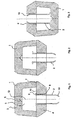
- FIG. 1 shows a longitudinal section through a feeder according to the invention parallel to the longitudinal axis 12.
- This is composed of a feeder head 1 and a tube-like body 2.
- the feeder head is composed of two parts, an upper part 3 and a lower part 4.
- First and second feeder part together form a Cavity 5 off.
- a recess 6 is further provided, which can receive the tip of a mandrel (not shown), with which the feeder can be positioned on a model (not shown).
- Upper feeder part 3 and lower feeder part 4 are above a bond. 7 connected with each other.
- an opening 8 is provided, which connects the cavity 5 with the environment. In the opening 8 of the tubular body 2 is inserted.
- the tubular body 2 has a circular cross-section. At its end facing the cavity 5, a stop 9 is provided, which rotates about the outer circumference of the tubular body 2.
- the diameter of the tubular body 2 is matched to the diameter of the opening 8, so that the tubular body 2 can be easily pushed into the cavity 5 or pulled out of it.
- At its end facing away from the cavity of the tubular body 2 terminates in a taper 10, which after formation of the mold contributes to the formation of a breaking edge.
- FIG. 1 the feeder according to the invention is shown in a state in which the tubular body 2 is completely pulled out of the feeder head 1.
- the stop 9 abuts against the surface 11, so that falling out of the tubular body 2 is prevented.
- Such a condition arises, for example, when the feeder is taken out of a package and held so that it is held down with the side from which the tubular body protrudes.
- FIG. 2 a state is shown in which the tubular body 2 is partially inserted into the feeder head 1.
- the tubular body 2 is inserted in the feeder head 1, that only a small resistance occurs during displacement of the tubular body 2.
- FIG. 2 Therefore, for example, corresponds to a state as it is taken after the compression of the molding material in the production of the mold.
- the feeder head 1 moves in the direction of the tubular body 2. Since the tubular body 2 stands up with its tapered end on the model, feeder head 1 and tubular body 2 move relative to each other.
- FIG. 3 a state is shown, as it is taken, for example, for shipping the feeder according to the invention.
- the feeder is doing relative to in FIG. 1 reversed position shown, so that the tubular body 2 slides into the cavity 5 of the feeder head 1 under the influence of gravity.
- the tubular body 2 thereby comes to the opposite side of the opening 8 of the cavity 5 on the inner surface of the feeder head 1 to the plant.
- the length of the tubular body 2 is chosen so that it is completely absorbed by the feeder head 1, so that the tapered end 10 of the tubular body 2 does not protrude beyond the end of the opening 8.
- the tubular body 2 can therefore not be damaged during transport.
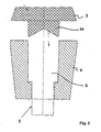
- FIG. 4 an embodiment of the feeder according to the invention is shown, in which the upper part 3 of the feeder head 1 has a flat, lid-shaped shape.
- the upper part 3 can for example consist of cardboard, an insulating or exothermic mass, as it is commonly used for the production of feeders, or even a ceramic material.
- a recess 6 is formed, which can receive the tip of a spring mandrel (not shown) to center the feeder according to the invention on a model (not shown) ,
- the upper part 3 and the lower part 4 together form a feeder head 1.
- upper part 3 and lower part 4 of the feeder head are connected, for example by gluing.
- Upper part 3 and lower part 4 have corresponding surfaces 13 a, b, on which a corresponding adhesive, such as water glass, is applied.
- a feeder head 1 is obtained which comprises a cavity 5.
- the lower part 4 of the feeder head 1 comprises an opening 8, in which a tubular body 2 is inserted.
- the tubular body is designed in such a way that it can be displaced in the direction of the longitudinal axis 12 of the feeder according to the invention.
- the tubular body 2 has a stop 9, which can come to rest on a corresponding surface 11 of the lower part 4.
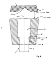
- FIG. 5 shows a further embodiment of the feeder according to the invention, this, similar to that in in FIG. 4 shown embodiment, a lid-shaped upper part 3 of the feeder head 1 has.
- the upper part 3, on its side facing the lower part 4 has an extension 14 which can be inserted into the recess of the lower part 4 forming the cavity 5.
- the outer periphery of the extension 14 is adapted in shape and size to the shape of the wall of the cavity 5.
- the diameter of the extension 14 may be approximately equal to the diameter of the upper portion of the cavity 5, so that the connection between the upper part 3 and lower part 4 is made by a clamping connection, which is produced by pressing the extension 14 into the cavity 5.
- protrusions may be provided on the peripheral surface of the extension 14 and the corresponding portions of the peripheral surface of the cavity, for example wedge-shaped projections, which destroys during the pressing of the upper part 3 in the lower part 4 be to produce a sufficiently stable clamping connection between the two parts 3, 4.
- the lower part 4 and the tubular body 2 essentially correspond to the corresponding parts of FIG FIG. 4 shown feeder.
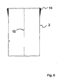
- FIG. 6 is a longitudinal section through a tube-like body shown, as used in the feeder according to the invention.
- the inner wall of the tubular runs Body parallel to the longitudinal axis 12 and do not taper to the lower end of the tubular body 2.
- wedge-shaped projections 15 are provided on the outside, which act according to the invention as a stop of the tubular body. If the tubular body 2 is analogous as in the FIGS. 1 to 5 shown inserted into a feeder head 1, the wedge-shaped projections 15 come into contact with the upper portion of the opening 8, so that the tubular body 2 can not fall out of the opening 8.
- the maximum strength of the wedge-shaped projections is therefore chosen so that the outer maximum distance of the wedge-shaped projections 15 is greater than the diameter of the opening eighth
Landscapes
- Engineering & Computer Science (AREA)
- Mechanical Engineering (AREA)
- Molds, Cores, And Manufacturing Methods Thereof (AREA)
- General Preparation And Processing Of Foods (AREA)
- Screw Conveyors (AREA)
- Feeding Of Articles To Conveyors (AREA)
- Chutes (AREA)
Claims (12)
- Dispositif d'alimentation pour coulée d'alliages non-ferreux, comprenant une tête d'alimentation (1), laquelle présente une cavité (5) ouverte vers l'extérieur par au moins une ouverture (8), et un corps tubulaire (2) qui passe à travers l'ouverture (8) et dans laquelle il est disposé de manière à pouvoir se déplacer, le corps tubulaire (2) présentant, sur son tronçon dirigé vers la cavité (5), une butée (9) qui peut venir plaquer contre une face adjacente à l'ouverture (8) dans la cavité (5).
- Dispositif d'alimentation selon la revendication 1, dans lequel la butée (9) est en forme de saillie annulaire qui entoure la périphérie extérieure du corps tubulaire (2).
- Dispositif d'alimentation selon la revendication 1 ou la revendication 2, dans lequel la butée (9) est disposée sur l'extrémité du corps tubulaire (2) dirigée vers la cavité (5).
- Dispositif d'alimentation selon l'une quelconque des revendications précédentes, dans lequel le corps tubulaire (2) a un diamètre extérieur beaucoup plus petit que le diamètre de l'ouverture (8) de sorte que le corps tubulaire (2) peut exécuter un mouvement de translation sous l'influence de son propre poids.
- Dispositif d'alimentation selon l'une quelconque des revendications précédentes, dans lequel le corps tubulaire (2) présente une extension dans le sens de son axe longitudinal, de sorte que le corps tubulaire (2), dans une position insérée, dans laquelle le corps tubulaire (2) est inséré dans la cavité (5) de la tête d'alimentation (1), ne dépasse pas de l'extrémité extérieure de l'ouverture (8).
- Dispositif d'alimentation selon l'une quelconque des revendications précédentes, dans lequel le corps tubulaire (2) présente une section circulaire.
- Dispositif d'alimentation selon l'une quelconque des revendications précédentes, dans lequel le corps tubulaire (2) se rétrécit sur son extrémité (10) opposée à la cavité.
- Dispositif d'alimentation selon l'une quelconque des revendications précédentes, dans lequel une face de la cavité, opposée à l'ouverture (8), forme une butée contre laquelle le corps tubulaire (2) vient plaquer lorsqu'il est en position insérée.
- Dispositif d'alimentation selon l'une quelconque des revendications précédentes, dans lequel la tête d'alimentation (1) est constituée d'au moins deux parties (3, 4) lesquelles sont reliées à la tête d'alimentation (1) par un moyen de liaison (7).
- Dispositif d'alimentation selon la revendication 9, dans lequel le moyen de liaison (7) est une colle.
- Dispositif d'alimentation selon l'une quelconque des revendications précédentes, dans lequel un évidement (6), destiné à recevoir et centrer un goujon, est prévu dans la tête d'alimentation (1).
- Procédé de fabrication d'un dispositif d'alimentation selon l'une quelconque des revendications 1 à 11,- qui fournit un corps tubulaire (2) qui présente une butée (9) ;- qui fournit une première partie (4) de dispositif d'alimentation qui présente une ouverture (8) ou un évidement adapté(e) à la périphérie du corps tubulaire (2) ;- dans lequel le corps tubulaire (2) est inséré dans l'ouverture (8) ou l'évidement, de sorte que la butée (9) du corps tubulaire (2) peut venir plaquer contre la face de la première partie (4) du dispositif d'alimentation entourant l'ouverture (8) ;- qui fournit une deuxième partie (3) de dispositif d'alimentation qui peut former, avec la première (4), une tête d'alimentation comportant une cavité (5) ;- dans lequel la première partie (4) et la deuxième partie (3) du dispositif d'alimentation sont reliées entre elles de telle façon que le corps tubulaire (2) vient plaquer contre une face de la tête d'alimentation (1), opposée à l'ouverture, lorsqu'il est en position insérée, et vient plaquer, avec la butée (9) contre la face (11) entourant l'ouverture (8), lorsqu'il est en position sortie.
Applications Claiming Priority (2)
| Application Number | Priority Date | Filing Date | Title |
|---|---|---|---|
| DE102005008324A DE102005008324A1 (de) | 2005-02-23 | 2005-02-23 | Speiser mit beweglicher Tülle |
| PCT/EP2006/001504 WO2006089699A1 (fr) | 2005-02-23 | 2006-02-20 | Dispositif d'alimentation a douille mobile |
Publications (2)
| Publication Number | Publication Date |
|---|---|
| EP1850987A1 EP1850987A1 (fr) | 2007-11-07 |
| EP1850987B1 true EP1850987B1 (fr) | 2010-01-27 |
Family
ID=36202484
Family Applications (1)
| Application Number | Title | Priority Date | Filing Date |
|---|---|---|---|
| EP06707086A Active EP1850987B1 (fr) | 2005-02-23 | 2006-02-20 | Dispositif d'alimentation a douille mobile |
Country Status (7)
| Country | Link |
|---|---|
| US (1) | US7934536B2 (fr) |
| EP (1) | EP1850987B1 (fr) |
| JP (1) | JP4423332B2 (fr) |
| AT (1) | ATE456408T1 (fr) |
| DE (2) | DE102005008324A1 (fr) |
| ES (1) | ES2341280T3 (fr) |
| WO (1) | WO2006089699A1 (fr) |
Cited By (3)
| Publication number | Priority date | Publication date | Assignee | Title |
|---|---|---|---|---|
| WO2014083155A1 (fr) | 2012-11-29 | 2014-06-05 | Gtp Schäfer Giesstechnische Produkte Gmbh | Procédé de fabrication d'une masselotte comportant un corps de masselotte exothermique ainsi qu'une coque extérieure isolante |
| EP2818262A1 (fr) | 2013-06-27 | 2014-12-31 | GTP-Schäfer Giesstechnische Produkte GmbH | Insert d'alimenteur avec pied d'alimenteur isolé |
| DE202022105722U1 (de) | 2022-10-11 | 2022-11-04 | Ask Chemicals Gmbh | Speiser mit beweglicher Tülle |
Families Citing this family (15)
| Publication number | Priority date | Publication date | Assignee | Title |
|---|---|---|---|---|
| DE102005025701B4 (de) | 2005-06-04 | 2007-03-08 | GTP Schäfer Gießtechnische Produkte GmbH | Speiser mit nachgiebigem Speiserunterteil |
| EP1920859A1 (fr) * | 2006-10-31 | 2008-05-14 | GTP-Schäfer Giesstechnische Produkte GmbH | Insert en deux parties pour masselotte avec un bas sous |
| DE102007061155A1 (de) | 2007-12-17 | 2009-06-18 | Gündogdu, Abdurrahman | Speiser |
| EP2792432A1 (fr) | 2013-04-16 | 2014-10-22 | Foseco International Limited | Élément d'alimentation |
| DE102013209775B3 (de) * | 2013-05-27 | 2014-10-23 | Chemex Gmbh | Speisereinsatz |
| CN105531053A (zh) * | 2013-07-02 | 2016-04-27 | 浇铸工艺产品有限责任公司 | 用于垂直分离的铸模的给料器插入件 |
| JP5960106B2 (ja) * | 2013-09-20 | 2016-08-02 | 曙ブレーキ工業株式会社 | キャリパ用鋳造装置に用いる金型、キャリパ用鋳造装置、およびキャリパの製造方法 |
| US9114452B2 (en) * | 2013-10-21 | 2015-08-25 | Mcconway & Torley, Llc | Method and system for casting metal |
| DE202014003503U1 (de) | 2014-04-29 | 2014-05-30 | Berning + Söhne GmbH & Co. KG | Speiser zur Befestigung an einer für das Gießen von Metallen verwendeten Gießform |
| GB201415516D0 (en) * | 2014-09-02 | 2014-10-15 | Foseco Int | Feeder system |
| US10286445B2 (en) | 2015-09-02 | 2019-05-14 | Foseco International Limited | Feeder system |
| EP3337631B1 (fr) | 2015-09-02 | 2020-01-29 | Foseco International Limited | Système d'alimentation |
| CN109365759B (zh) * | 2018-12-20 | 2021-01-15 | 苏州石川制铁有限公司 | 一种轮毂轴承单元的铸造方法 |
| DE202021106147U1 (de) | 2021-11-10 | 2022-11-14 | Ask Chemicals Gmbh | Speiser |
| DE202023100381U1 (de) | 2023-01-27 | 2024-01-30 | Ask Chemicals Gmbh | Speiser mit Deckel |
Family Cites Families (6)
| Publication number | Priority date | Publication date | Assignee | Title |
|---|---|---|---|---|
| DE3621334C1 (en) | 1986-06-26 | 1988-02-18 | Hagenburger Chamotte Ton | Method and device for the production of metallic mouldings |
| DE4119192A1 (de) | 1991-06-11 | 1992-12-17 | Hoesch Ag | Federnder dorn zum halten von speisern |
| JPH08103850A (ja) | 1994-09-30 | 1996-04-23 | Kurimoto Ltd | 鋳造用の押湯ネックダウンコア |
| DE19642838A1 (de) | 1996-10-17 | 1997-07-31 | Daimler Benz Ag | Speiser für ein metallisches Gußwerkstück |
| DE20115140U1 (de) * | 2000-11-30 | 2002-01-31 | Luengen Gmbh & Co Kg As | Speiser mit einem rohrähnlichen Körper |
| DE10142357B4 (de) * | 2001-08-30 | 2013-10-17 | Ask Chemicals Feeding Systems Gmbh | Speiser mit einem rohrähnlichen Körper |
-
2005
- 2005-02-23 DE DE102005008324A patent/DE102005008324A1/de not_active Withdrawn
-
2006
- 2006-02-20 US US11/816,679 patent/US7934536B2/en active Active
- 2006-02-20 EP EP06707086A patent/EP1850987B1/fr active Active
- 2006-02-20 DE DE502006006038T patent/DE502006006038D1/de active Active
- 2006-02-20 AT AT06707086T patent/ATE456408T1/de active
- 2006-02-20 JP JP2007556541A patent/JP4423332B2/ja active Active
- 2006-02-20 WO PCT/EP2006/001504 patent/WO2006089699A1/fr active Application Filing
- 2006-02-20 ES ES06707086T patent/ES2341280T3/es active Active
Cited By (4)
| Publication number | Priority date | Publication date | Assignee | Title |
|---|---|---|---|---|
| WO2014083155A1 (fr) | 2012-11-29 | 2014-06-05 | Gtp Schäfer Giesstechnische Produkte Gmbh | Procédé de fabrication d'une masselotte comportant un corps de masselotte exothermique ainsi qu'une coque extérieure isolante |
| EP2818262A1 (fr) | 2013-06-27 | 2014-12-31 | GTP-Schäfer Giesstechnische Produkte GmbH | Insert d'alimenteur avec pied d'alimenteur isolé |
| DE202022105722U1 (de) | 2022-10-11 | 2022-11-04 | Ask Chemicals Gmbh | Speiser mit beweglicher Tülle |
| WO2024079189A1 (fr) | 2022-10-11 | 2024-04-18 | Ask Chemicals Gmbh | Colonne montante avec un bec verseur mobile |
Also Published As
| Publication number | Publication date |
|---|---|
| ATE456408T1 (de) | 2010-02-15 |
| DE102005008324A1 (de) | 2006-08-24 |
| US20080223543A1 (en) | 2008-09-18 |
| ES2341280T3 (es) | 2010-06-17 |
| JP4423332B2 (ja) | 2010-03-03 |
| DE502006006038D1 (de) | 2010-03-18 |
| WO2006089699A1 (fr) | 2006-08-31 |
| EP1850987A1 (fr) | 2007-11-07 |
| US7934536B2 (en) | 2011-05-03 |
| JP2008531287A (ja) | 2008-08-14 |
Similar Documents
| Publication | Publication Date | Title |
|---|---|---|
| EP1850987B1 (fr) | Dispositif d'alimentation a douille mobile | |
| EP1345716B1 (fr) | Masselotte presentant un corps tubulaire | |
| EP2097193B1 (fr) | Insert d'alimenteur et élément alimenteur | |
| EP1732719B1 (fr) | Masselotte a manchon deformable | |
| EP1184104A1 (fr) | Insert pour masselotte | |
| EP3003601B2 (fr) | Manchon de masselotte, élément de formage du manchon de masselotte et procédé de coulée de métal les utilisant | |
| DE102005019385A1 (de) | Filterspeiser und Verfahren zur Herstellung einer Giessform | |
| EP2982458B1 (fr) | Systeme a utiliser lors de la production d'un moule divisible | |
| WO2000071282A1 (fr) | Dispositif pour l'assemblage de pieces de tout type | |
| DE2751231A1 (de) | Einstellbare giessform | |
| EP1920859A1 (fr) | Insert en deux parties pour masselotte avec un bas sous | |
| WO2019120804A1 (fr) | Procédé de production d'une partie de moule ainsi qu'insert d'alimentation destiné à être utilisé dans un tel procédé | |
| WO2005095021A2 (fr) | Alimentateur a ecran ou a chevilles | |
| DE10142357B4 (de) | Speiser mit einem rohrähnlichen Körper | |
| EP2956256B1 (fr) | Insert de dispositif d'alimentation et procédé permettant d'agencer ledit insert dans un moule | |
| DE102019104180A1 (de) | Einteiliger Speiserkörper zur Verwendung beim Gießen von Metallen | |
| DE10059481B4 (de) | Speiser mit einem rohrähnlichen Körper | |
| EP1779944B1 (fr) | Masselotte avec bouchon pour fermer sa entrée | |
| EP3917698B1 (fr) | Corps de masselotte en une pièce a utiliser lors du coulage de métaux | |
| EP3819042A1 (fr) | Insert d'alimentation pourvu de pied métallique à ressort | |
| DE202013104863U1 (de) | Speisereinsatz mit einem in seinem Deckelbereich angeordneten Stopfen | |
| DE102017119443B3 (de) | Eingussspeiser mit integriertem Filter | |
| WO2022180103A1 (fr) | Dispositif d'alimentation divisé verticalement destiné à être utilisé lors de la coulée de métaux dans des moules de coulée, et son procédé de production | |
| DE102022106807A1 (de) | Speiser und Speisersystem für Gießformen | |
| WO2016050264A1 (fr) | Insert d'alimentation destiné à un moule de coulée divisé verticalement |
Legal Events
| Date | Code | Title | Description |
|---|---|---|---|
| PUAI | Public reference made under article 153(3) epc to a published international application that has entered the european phase |
Free format text: ORIGINAL CODE: 0009012 |
|
| 17P | Request for examination filed |
Effective date: 20070905 |
|
| AK | Designated contracting states |
Kind code of ref document: A1 Designated state(s): AT BE BG CH CY CZ DE DK EE ES FI FR GB GR HU IE IS IT LI LT LU LV MC NL PL PT RO SE SI SK TR |
|
| DAX | Request for extension of the european patent (deleted) | ||
| GRAP | Despatch of communication of intention to grant a patent |
Free format text: ORIGINAL CODE: EPIDOSNIGR1 |
|
| RAP1 | Party data changed (applicant data changed or rights of an application transferred) |
Owner name: AS LUENGEN GMBH |
|
| GRAS | Grant fee paid |
Free format text: ORIGINAL CODE: EPIDOSNIGR3 |
|
| GRAA | (expected) grant |
Free format text: ORIGINAL CODE: 0009210 |
|
| AK | Designated contracting states |
Kind code of ref document: B1 Designated state(s): AT BE BG CH CY CZ DE DK EE ES FI FR GB GR HU IE IS IT LI LT LU LV MC NL PL PT RO SE SI SK TR |
|
| REG | Reference to a national code |
Ref country code: GB Ref legal event code: FG4D Free format text: NOT ENGLISH |
|
| REG | Reference to a national code |
Ref country code: CH Ref legal event code: EP |
|
| REG | Reference to a national code |
Ref country code: IE Ref legal event code: FG4D |
|
| REF | Corresponds to: |
Ref document number: 502006006038 Country of ref document: DE Date of ref document: 20100318 Kind code of ref document: P |
|
| REG | Reference to a national code |
Ref country code: NL Ref legal event code: VDEP Effective date: 20100127 |
|
| REG | Reference to a national code |
Ref country code: ES Ref legal event code: FG2A Ref document number: 2341280 Country of ref document: ES Kind code of ref document: T3 |
|
| LTIE | Lt: invalidation of european patent or patent extension |
Effective date: 20100127 |
|
| PG25 | Lapsed in a contracting state [announced via postgrant information from national office to epo] |
Ref country code: PT Free format text: LAPSE BECAUSE OF FAILURE TO SUBMIT A TRANSLATION OF THE DESCRIPTION OR TO PAY THE FEE WITHIN THE PRESCRIBED TIME-LIMIT Effective date: 20100527 Ref country code: NL Free format text: LAPSE BECAUSE OF FAILURE TO SUBMIT A TRANSLATION OF THE DESCRIPTION OR TO PAY THE FEE WITHIN THE PRESCRIBED TIME-LIMIT Effective date: 20100127 Ref country code: LT Free format text: LAPSE BECAUSE OF FAILURE TO SUBMIT A TRANSLATION OF THE DESCRIPTION OR TO PAY THE FEE WITHIN THE PRESCRIBED TIME-LIMIT Effective date: 20100127 Ref country code: IS Free format text: LAPSE BECAUSE OF FAILURE TO SUBMIT A TRANSLATION OF THE DESCRIPTION OR TO PAY THE FEE WITHIN THE PRESCRIBED TIME-LIMIT Effective date: 20100527 |
|
| REG | Reference to a national code |
Ref country code: IE Ref legal event code: FD4D |
|
| BERE | Be: lapsed |
Owner name: AS LUNGEN G.M.B.H. Effective date: 20100228 |
|
| PG25 | Lapsed in a contracting state [announced via postgrant information from national office to epo] |
Ref country code: FI Free format text: LAPSE BECAUSE OF FAILURE TO SUBMIT A TRANSLATION OF THE DESCRIPTION OR TO PAY THE FEE WITHIN THE PRESCRIBED TIME-LIMIT Effective date: 20100127 Ref country code: LV Free format text: LAPSE BECAUSE OF FAILURE TO SUBMIT A TRANSLATION OF THE DESCRIPTION OR TO PAY THE FEE WITHIN THE PRESCRIBED TIME-LIMIT Effective date: 20100127 Ref country code: PL Free format text: LAPSE BECAUSE OF FAILURE TO SUBMIT A TRANSLATION OF THE DESCRIPTION OR TO PAY THE FEE WITHIN THE PRESCRIBED TIME-LIMIT Effective date: 20100127 Ref country code: SI Free format text: LAPSE BECAUSE OF FAILURE TO SUBMIT A TRANSLATION OF THE DESCRIPTION OR TO PAY THE FEE WITHIN THE PRESCRIBED TIME-LIMIT Effective date: 20100127 |
|
| REG | Reference to a national code |
Ref country code: CH Ref legal event code: PL |
|
| PG25 | Lapsed in a contracting state [announced via postgrant information from national office to epo] |
Ref country code: SE Free format text: LAPSE BECAUSE OF FAILURE TO SUBMIT A TRANSLATION OF THE DESCRIPTION OR TO PAY THE FEE WITHIN THE PRESCRIBED TIME-LIMIT Effective date: 20100127 Ref country code: RO Free format text: LAPSE BECAUSE OF FAILURE TO SUBMIT A TRANSLATION OF THE DESCRIPTION OR TO PAY THE FEE WITHIN THE PRESCRIBED TIME-LIMIT Effective date: 20100127 Ref country code: CH Free format text: LAPSE BECAUSE OF NON-PAYMENT OF DUE FEES Effective date: 20100228 Ref country code: CY Free format text: LAPSE BECAUSE OF FAILURE TO SUBMIT A TRANSLATION OF THE DESCRIPTION OR TO PAY THE FEE WITHIN THE PRESCRIBED TIME-LIMIT Effective date: 20100127 Ref country code: MC Free format text: LAPSE BECAUSE OF NON-PAYMENT OF DUE FEES Effective date: 20100301 Ref country code: LI Free format text: LAPSE BECAUSE OF NON-PAYMENT OF DUE FEES Effective date: 20100228 Ref country code: IE Free format text: LAPSE BECAUSE OF FAILURE TO SUBMIT A TRANSLATION OF THE DESCRIPTION OR TO PAY THE FEE WITHIN THE PRESCRIBED TIME-LIMIT Effective date: 20100127 Ref country code: GR Free format text: LAPSE BECAUSE OF FAILURE TO SUBMIT A TRANSLATION OF THE DESCRIPTION OR TO PAY THE FEE WITHIN THE PRESCRIBED TIME-LIMIT Effective date: 20100428 Ref country code: EE Free format text: LAPSE BECAUSE OF FAILURE TO SUBMIT A TRANSLATION OF THE DESCRIPTION OR TO PAY THE FEE WITHIN THE PRESCRIBED TIME-LIMIT Effective date: 20100127 |
|
| PG25 | Lapsed in a contracting state [announced via postgrant information from national office to epo] |
Ref country code: SK Free format text: LAPSE BECAUSE OF FAILURE TO SUBMIT A TRANSLATION OF THE DESCRIPTION OR TO PAY THE FEE WITHIN THE PRESCRIBED TIME-LIMIT Effective date: 20100127 Ref country code: BG Free format text: LAPSE BECAUSE OF FAILURE TO SUBMIT A TRANSLATION OF THE DESCRIPTION OR TO PAY THE FEE WITHIN THE PRESCRIBED TIME-LIMIT Effective date: 20100427 Ref country code: CZ Free format text: LAPSE BECAUSE OF FAILURE TO SUBMIT A TRANSLATION OF THE DESCRIPTION OR TO PAY THE FEE WITHIN THE PRESCRIBED TIME-LIMIT Effective date: 20100127 |
|
| PLBE | No opposition filed within time limit |
Free format text: ORIGINAL CODE: 0009261 |
|
| STAA | Information on the status of an ep patent application or granted ep patent |
Free format text: STATUS: NO OPPOSITION FILED WITHIN TIME LIMIT |
|
| 26N | No opposition filed |
Effective date: 20101028 |
|
| PG25 | Lapsed in a contracting state [announced via postgrant information from national office to epo] |
Ref country code: DK Free format text: LAPSE BECAUSE OF FAILURE TO SUBMIT A TRANSLATION OF THE DESCRIPTION OR TO PAY THE FEE WITHIN THE PRESCRIBED TIME-LIMIT Effective date: 20100127 |
|
| PG25 | Lapsed in a contracting state [announced via postgrant information from national office to epo] |
Ref country code: BE Free format text: LAPSE BECAUSE OF NON-PAYMENT OF DUE FEES Effective date: 20100228 |
|
| REG | Reference to a national code |
Ref country code: DE Ref legal event code: R082 Ref document number: 502006006038 Country of ref document: DE Representative=s name: MUELLER SCHUPFNER & PARTNER PATENT- UND RECHTS, DE |
|
| REG | Reference to a national code |
Ref country code: DE Ref legal event code: R082 Ref document number: 502006006038 Country of ref document: DE Representative=s name: MUELLER SCHUPFNER & PARTNER PATENT- UND RECHTS, DE Effective date: 20120203 Ref country code: DE Ref legal event code: R081 Ref document number: 502006006038 Country of ref document: DE Owner name: ASK CHEMICALS FEEDING SYSTEMS GMBH, DE Free format text: FORMER OWNER: AS LUENGEN GMBH, 56170 BENDORF, DE Effective date: 20120203 |
|
| PG25 | Lapsed in a contracting state [announced via postgrant information from national office to epo] |
Ref country code: LU Free format text: LAPSE BECAUSE OF NON-PAYMENT OF DUE FEES Effective date: 20100220 Ref country code: HU Free format text: LAPSE BECAUSE OF FAILURE TO SUBMIT A TRANSLATION OF THE DESCRIPTION OR TO PAY THE FEE WITHIN THE PRESCRIBED TIME-LIMIT Effective date: 20100728 |
|
| REG | Reference to a national code |
Ref country code: AT Ref legal event code: MM01 Ref document number: 456408 Country of ref document: AT Kind code of ref document: T Effective date: 20110220 |
|
| PG25 | Lapsed in a contracting state [announced via postgrant information from national office to epo] |
Ref country code: AT Free format text: LAPSE BECAUSE OF NON-PAYMENT OF DUE FEES Effective date: 20110220 |
|
| REG | Reference to a national code |
Ref country code: FR Ref legal event code: PLFP Year of fee payment: 11 |
|
| REG | Reference to a national code |
Ref country code: FR Ref legal event code: PLFP Year of fee payment: 12 |
|
| REG | Reference to a national code |
Ref country code: FR Ref legal event code: PLFP Year of fee payment: 13 |
|
| PGFP | Annual fee paid to national office [announced via postgrant information from national office to epo] |
Ref country code: FR Payment date: 20230217 Year of fee payment: 18 |
|
| PGFP | Annual fee paid to national office [announced via postgrant information from national office to epo] |
Ref country code: TR Payment date: 20230216 Year of fee payment: 18 Ref country code: IT Payment date: 20230228 Year of fee payment: 18 |
|
| P01 | Opt-out of the competence of the unified patent court (upc) registered |
Effective date: 20230517 |
|
| PGFP | Annual fee paid to national office [announced via postgrant information from national office to epo] |
Ref country code: DE Payment date: 20230426 Year of fee payment: 18 |
|
| PGFP | Annual fee paid to national office [announced via postgrant information from national office to epo] |
Ref country code: ES Payment date: 20240319 Year of fee payment: 19 |
|
| PGFP | Annual fee paid to national office [announced via postgrant information from national office to epo] |
Ref country code: GB Payment date: 20240222 Year of fee payment: 19 |