EP2815883B1 - Flüssigkeitsausstoßkopf - Google Patents
Flüssigkeitsausstoßkopf Download PDFInfo
- Publication number
- EP2815883B1 EP2815883B1 EP14002047.0A EP14002047A EP2815883B1 EP 2815883 B1 EP2815883 B1 EP 2815883B1 EP 14002047 A EP14002047 A EP 14002047A EP 2815883 B1 EP2815883 B1 EP 2815883B1
- Authority
- EP
- European Patent Office
- Prior art keywords
- sealant
- liquid discharge
- discharge head
- substrate
- recording element
- Prior art date
- Legal status (The legal status is an assumption and is not a legal conclusion. Google has not performed a legal analysis and makes no representation as to the accuracy of the status listed.)
- Active
Links
- 239000007788 liquid Substances 0.000 title claims description 43
- 239000000565 sealant Substances 0.000 claims description 152
- 239000000758 substrate Substances 0.000 claims description 68
- 230000000903 blocking effect Effects 0.000 claims description 26
- 239000003795 chemical substances by application Substances 0.000 claims description 12
- 229920005989 resin Polymers 0.000 claims description 12
- 239000011347 resin Substances 0.000 claims description 12
- 238000007789 sealing Methods 0.000 claims description 12
- 238000007599 discharging Methods 0.000 claims description 4
- 239000000945 filler Substances 0.000 claims description 4
- 239000003822 epoxy resin Substances 0.000 claims description 3
- 229920000647 polyepoxide Polymers 0.000 claims description 3
- 239000000976 ink Substances 0.000 description 29
- 238000000034 method Methods 0.000 description 10
- 238000010586 diagram Methods 0.000 description 8
- 230000005764 inhibitory process Effects 0.000 description 8
- XUIMIQQOPSSXEZ-UHFFFAOYSA-N Silicon Chemical compound [Si] XUIMIQQOPSSXEZ-UHFFFAOYSA-N 0.000 description 6
- 229910052710 silicon Inorganic materials 0.000 description 6
- 239000010703 silicon Substances 0.000 description 6
- 239000000853 adhesive Substances 0.000 description 4
- 230000001070 adhesive effect Effects 0.000 description 4
- 238000005304 joining Methods 0.000 description 3
- 238000000926 separation method Methods 0.000 description 3
- 229930185605 Bisphenol Natural products 0.000 description 2
- IISBACLAFKSPIT-UHFFFAOYSA-N bisphenol A Chemical compound C=1C=C(O)C=CC=1C(C)(C)C1=CC=C(O)C=C1 IISBACLAFKSPIT-UHFFFAOYSA-N 0.000 description 2
- 239000004020 conductor Substances 0.000 description 2
- 238000004519 manufacturing process Methods 0.000 description 2
- 239000000203 mixture Substances 0.000 description 2
- 239000003566 sealing material Substances 0.000 description 2
- 230000008961 swelling Effects 0.000 description 2
- PNEYBMLMFCGWSK-UHFFFAOYSA-N aluminium oxide Inorganic materials [O-2].[O-2].[O-2].[Al+3].[Al+3] PNEYBMLMFCGWSK-UHFFFAOYSA-N 0.000 description 1
- 238000004140 cleaning Methods 0.000 description 1
- 230000000052 comparative effect Effects 0.000 description 1
- 238000011161 development Methods 0.000 description 1
- 230000018109 developmental process Effects 0.000 description 1
- 239000000428 dust Substances 0.000 description 1
- 230000000694 effects Effects 0.000 description 1
- 238000005429 filling process Methods 0.000 description 1
- 238000010438 heat treatment Methods 0.000 description 1
- 238000001746 injection moulding Methods 0.000 description 1
- 230000010354 integration Effects 0.000 description 1
- 239000000463 material Substances 0.000 description 1
- 238000003825 pressing Methods 0.000 description 1
- 230000001681 protective effect Effects 0.000 description 1
Images


Classifications
-
- B—PERFORMING OPERATIONS; TRANSPORTING
- B41—PRINTING; LINING MACHINES; TYPEWRITERS; STAMPS
- B41J—TYPEWRITERS; SELECTIVE PRINTING MECHANISMS, i.e. MECHANISMS PRINTING OTHERWISE THAN FROM A FORME; CORRECTION OF TYPOGRAPHICAL ERRORS
- B41J2/00—Typewriters or selective printing mechanisms characterised by the printing or marking process for which they are designed
- B41J2/005—Typewriters or selective printing mechanisms characterised by the printing or marking process for which they are designed characterised by bringing liquid or particles selectively into contact with a printing material
- B41J2/01—Ink jet
- B41J2/135—Nozzles
- B41J2/14—Structure thereof only for on-demand ink jet heads
- B41J2/14016—Structure of bubble jet print heads
- B41J2/14072—Electrical connections, e.g. details on electrodes, connecting the chip to the outside...
Definitions
- the present invention relates to a liquid discharge head that discharges liquid, such as ink.
- a recording method using a liquid discharge head involves supplying thermal and vibration energy to liquid, such as ink, and discharging the ink in the form of micro-droplets through discharge ports to form an image on a recording medium.
- a method for manufacturing such an inkjet head is disclosed in Japanese Patent Laid-Open No. 2002-019120 .
- discharge energy generating elements and wiring conductors for supplying power to the discharge energy generating elements are mounted on a silicon substrate. Then, after a protective film is provided over the wiring conductors, an ink flow path and ink discharge ports are patterned with a resist. Next, a through hole (ink supply port) for supplying ink from the back side of the silicon substrate to the discharge energy generating elements is formed in the silicon substrate.
- the resultant recording element substrate is attached to a support plate made of alumina or the like, so that the recording element substrate is electrically joined to an electric wiring member.
- a perimeter sealant is applied to protect side faces of the recording element substrate from ink and dust.
- an inner lead bonding (ILB) sealant (electric-connection sealant) for sealing electric connections is applied over the perimeter sealant.
- the perimeter sealant is required to quickly flow through a gap with a width of nearly 1 mm between a part on the support plate and the recording element substrate, and to fill the gap in a short time. Additionally, the perimeter sealant is required to protect the recording element substrate from ink and other things.
- the electric-connection sealant is required not only to seal electric connections, but also to be resistant to rubbing with a blade or wiper for cleaning the area of ink discharge ports and to contact with paper caused by a paper jam.
- WO 2010/143565 A1 discloses a liquid discharge recording head that includes a recording element substrate, an electric wiring board, and a supporting plate that supports the recording element substrate and the electric wiring board, wherein a gap is formed between the recording element substrate and the electric wiring board.
- the liquid discharge recording head further includes a connecting member that electrically connects, across the gap, an electrode provided in the recording element substrate and an electrode terminal provided in the electric wiring board.
- a first resin agent is filled in the gap
- a second resin agent seals the electrode, the electrode terminal, and the connecting member
- a third resin agent is provided between the first resin agent and the supporting plate and has a lower modulus of elasticity than the first resin agent and the second resin agent.
- US 2012/0176451 A1 discloses a method of producing a liquid ejection head comprising an element substrate with energy generating elements that generate energy for ejecting liquid, and a support member configured to support the element substrate and having a recess for accommodating the element substrate.
- the method includes providing an adhesive on a bottom surface of the recess, positioning the element substrate in the recess and pressing the adhesive to introduce a portion of the adhesive into a space between a protrusion protruding inward from an inner surface of the recess and the element substrate, and sealing a connected portion of the connecting terminals and the lead wires with a sealing material, wherein the sealing material is prevented from flowing by a portion of the adhesive filling the space between the protrusion and the element substrate.
- a method for applying the two types of sealants, the perimeter sealant and the electric-connection sealant is disclosed in Japanese Patent Laid-Open No. 2005-132102 .
- This document describes a method in which a hardness of the electric-connection sealant after curing is higher than that of the perimeter sealant after curing and a main component and a curing agent of the electric-connection sealant are the same as those of the perimeter sealant.
- a hardness of the electric-connection sealant after curing is higher than that of the perimeter sealant after curing and a main component and a curing agent of the electric-connection sealant are the same as those of the perimeter sealant.
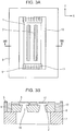
- Fig. 3A is a diagram of a long and high-density inkjet recording head, as viewed from a direction in which ink is discharged.
- Fig. 3B is a cross-sectional view taken along line IIIB-IIIB in Fig. 3A .
- a recording element substrate 1 is provided with two ink supply ports 16 and four rows of discharge ports. The two ink supply ports 16 are filled with the same type of ink, which is then discharged therefrom.
- the two ink supply ports 16 extending in the longitudinal direction of the recording element substrate 1 are arranged in parallel, and the recording element substrate 1 is long in length. Therefore, side faces of the central part of the recording element substrate 1 in the longitudinal direction are structurally sensitive to stress.
- the electric-connection sealant has the function of protecting leads and thus has a high elastic modulus (high hardness).
- the perimeter sealant has a hardness lower than that of the electric-connection sealant.
- the perimeter sealant contains the same main component and curing agent as those of the electric-connection sealant, the perimeter sealant has to have a certain degree of hardness. Because the perimeter sealant is in contact with ink, it may absorb the ink and swell depending on the use environment. As a result, stress may be applied to side faces of the central part of the recording element substrate 1. Such a configuration in which stress is applied to the side faces of the central part of the recording element substrate 1 by swelling of the perimeter sealant has not been seen as a problem.
- the resulting stress may deform the recording element substrate 1 and flow path members 17, and may negatively affect the print quality. Flexibility in ink selection may be lost, and high image quality with good color developing properties may not be achieved.
- the present invention provides a liquid discharge head as defined in claim 1.
- the other claims relate to further developments.
- Fig. 2 is a schematic perspective view illustrating a structure of a liquid discharge head according to the first embodiment of the present invention.
- the recording element substrate 1 includes a silicon substrate having discharge energy generating elements 2 thereon.
- the discharge energy generating elements 2 are for generating energy to be used for discharging liquid, such as ink.
- Discharge ports 3 are for discharging ink, and a subtank 4 is for temporarily storing ink to be discharged.
- An electric wiring member 5 is connected via leads (electric connections) 6 to terminal areas of the recording element substrate 1, to which the electric wiring member 5 transmits an electric signal for driving the discharge energy generating elements 2.
- a support member 7 supports the recording element substrate 1.
- a plate 8 (see Fig. 3B ) supports the electric wiring member 5.
- Blocking portions 10 each separate an under-lead sealant and a perimeter sealant (described below).
- An over-lead sealant (third sealant) 11 is for protecting an upper region of the leads 6.
- the recording element substrate 1 is composed of the silicon substrate (described above) having the discharge energy generating elements 2 thereon, and flow path members 17 above the silicon substrate.
- the flow path members 17 form flow paths for supplying ink.
- Fig. 1 is a diagram illustrating a recording element unit 14 according to the first embodiment of the present invention.
- An under-lead sealant (first sealant) 12 is provided between the recording element substrate 1 and the plate 8 for sealing a gap in a region where the leads 6 are present.
- a perimeter sealant (second sealant) 13 is provided between the recording element substrate 1 and the plate 8 for sealing a gap in a region where no lead is present.
- the blocking portions 10 each separate the perimeter sealant 13 and the under-lead sealant 12 for sealing a lower region of the leads 6.
- the recording element unit 14 having the structure described above is joined to the subtank 4 to form the liquid discharge head.
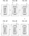
- the recording element unit 14 is made by a sealant application process illustrated in the diagrams of Figs. 4A to 4F .
- the recording element substrate 1 of the present embodiment is 3.6 mm by 32.5 mm in size (X-direction by Y-direction in Fig. 1 ), and 0.62 mm in thickness.
- a gap in a region where the leads 6 are present is 0.6 mm.
- a gap in a region where no lead is present is 1.8 mm.
- Fig. 4A illustrates the recording element unit 14 before application of each sealant thereto.
- the recording element unit 14 is in a state where, after the recording element substrate 1 and the plate 8 are mounted on the support member 7, the electric wiring member 5 is mounted over the plate 8 to electrically join the electric wiring member 5 to the recording element substrate 1.
- the over-lead sealant 11 which is the same as a sealant for sealing an upper part of inner lead bonding (ILB) is applied to part of side faces of the recording element substrate 1 in the longitudinal direction, and semi-cured to form the blocking portions 10.
- the recording element unit 14 having the over-lead sealant 11 applied thereto is allowed to stand for three minutes on a 150°C hot plate so as to semi-cure the over-lead sealant 11.
- a reason for using the over-lead sealant 11 to form the blocking portions 10 is that the over-lead sealant 11 has high thixotropy. To realize the function of the blocking portions 10, it is not necessary to completely cure the over-lead sealant 11.
- the over-lead sealant 11 can be completely cured in a subsequent sealant curing step, it is only necessary at this stage that the over-lead sealant 11 be semi-cured. Thus, the takt time can be shortened. Also, because of the high thixotropy, the flow of the over-lead sealant 11 to other regions can be reduced, and thus the blocking portions 10 can extend to a point near the upper surface of the recording element substrate 1 (in the Z-direction in Fig. 2 ).
- the under-lead sealant (first sealant) 12 is applied to under-ILB sealing portions 15. Due to space limitations, the under-lead sealant 12 cannot be directly applied under the leads 6 with a dispenser. Therefore, with the dispenser, the under-lead sealant 12 is applied to regions on both sides of each lead area, and then is allowed to flow under the leads 6. In the present embodiment, after being applied, the under-lead sealant 12 is allowed to stand for three minutes until it flows under the leads 6 and reaches the state of Fig. 4D .
- the composition of the main component and the curing agent of the under-lead sealant 12 is made the same as that of the over-lead sealant (third sealant) 11 to be applied later.
- the amount of filler contained in the under-lead sealant 12 is made smaller than that in the over-lead sealant 11.
- the over-lead sealant 11 and the under-lead sealant 12 may contain the same type of resin. Additionally, the over-lead sealant 11 and the under-lead sealant 12 may contain the same type of curing agent.
- the molecular weight of the resin in the over-lead sealant 11 may differ from that of the resin in the under-lead sealant 12.
- both the over-lead sealant 11 and the under-lead sealant 12 use bisphenol A-type epoxy resin as a main component.
- the perimeter sealant (second sealant) 13 is applied to regions where no lead is present, the regions being in a gap around the perimeter of the recording element substrate 1.
- the perimeter sealant 13 is applied to side faces where no lead is present, the side faces each being one of a plurality of side faces of the recording element substrate 1 of rectangular shape and extending in the longitudinal direction.
- a sealant which is relatively soft (small in elastic modulus) even after being cured is used as the perimeter sealant 13.
- the elastic modulus of the third sealant is the largest, that of the first sealant is the second, and that of the second sealant is the smallest (i.e., second sealant ⁇ first sealant ⁇ third sealant).
- the over-lead sealant (third sealant) 11 is applied over the leads 6 (over the under-lead sealant 12). Then, to cure the under-lead sealant 12 and the perimeter sealant 13 together with the blocking portions 10 formed by application of the over-lead sealant 11, the recording element unit 14 is placed in a 150°C oven and heated for 3.5 hours.
- curing inhibition is reduced in joining force between the under-lead sealant 12 and the over-lead sealant 11. Since the blocking portions 10 are formed by the over-lead sealant 11, a strong joining force between each blocking portion 10 and the under-lead sealant 12 is ensured. As for joining between each blocking portion 10 and the perimeter sealant 13, curing inhibition, such as separation of their joint faces, may occur due to the difference in material composition. However, even if curing inhibition occurs, the corresponding area is distant from the leads 6. Therefore, even if separation occurs and ink enters the area of separation, further entry of the ink can be blocked by good interfacial adhesion between the blocking portion 10 and the under-lead sealant 12.
- the blocking portions 10 are relatively high in stiffness, because of the properties of the over-lead sealant 11 used. If stiffness of the sealant used to form the blocking portions 10 is too high, the sealant may absorb ink and swell, and may apply excessive pressure to the recording element substrate 1. However, since the blocking portions 10 are small in size and the recording element substrate 1 is subjected to stress in only small regions of the side faces thereof, the resulting impact on the recording element substrate 1 is limited.
- the blocking portions 10 are formed near both ends of each side face of the recording element substrate 1 in the longitudinal direction. Therefore, the recording element substrate 1 is structurally more resistant to stress (deformation) at both end portions than in the central part. Thus, even if stress is applied by the blocking portions 10 to the recording element substrate 1, the resulting impact can be reduced.
- the recording element unit 14 made as described above is joined to the subtank 4 to form a liquid discharge head.
- This liquid discharge head was stored for one week at 70°C, with an upper surface of the recording element substrate 1 immersed in ink, on the basis of the assumption that the liquid discharge head would be used under severe conditions.
- good print quality was achieved.
- good print quality was not achieved when printing was performed, under the same use conditions as above, with a recording element substrate (see Figs. 3A and 3B ) serving as a comparative example not using the configuration of the present invention.
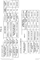
- Fig. 6 shows a list of sealants used in each part in the first embodiment and properties of the sealants. The advantageous effects of the present invention were confirmed in the range of property values of each sealant shown in Fig. 6 .
- the over-lead sealant 11 and the under-lead sealant 12 contain the same type of resin (bisphenol A-type epoxy resin). This reduces curing inhibition between the over-lead sealant 11 and the under-lead sealant 12.
- Fig. 5 is a diagram illustrating a liquid discharge head where multiple recording element substrates 1 are arranged on a support member. Referring to Fig. 5 , gaps 18 are created between adjacent recording element substrates 1 parallel to each other. In this liquid discharge head, each sealant can be applied also by the sealant application process illustrated in Figs. 4A to 4F . The gaps 18 are filled with the under-lead sealant 12 by capillary force. To shorten the takt time in the sealing and filling process of the present embodiment, the recording element substrates 1 are placed in a 40°C oven and heated for about an hour. This is a temperature at which curing of the under-lead sealant 12 does not start and the viscosity of the sealant can be lowered. The step of heating other sealants is the same as that in the first embodiment.
- the under-lead sealant 12 in the gaps 18 may swell by absorbing ink depending on the use conditions, and may apply pressure to the central parts of the recording element substrates 1. Because the gaps 18 are minimized in width to reduce the size of the liquid discharge head, the volume of the under-lead sealant 12 applied to the gaps 18 is small and the amount of resulting stress is relatively small. Therefore, it is possible to reduce deformation of the flow path members 17 formed over each recording element substrate 1. In the present embodiment, a liquid discharge head with gaps 18 each being 120 ⁇ m in width (i.e., length in the X-direction) was made. Good print quality was achieved when printing was performed with this liquid discharge head under the same use conditions as those in the first embodiment.
- sealants used in the present embodiment properties of the sealants, and curing conditions are the same as those shown in Fig. 6 .
- the gaps 18 may be provided with blocking portions 10, and the perimeter sealant 13 may be applied between the blocking portions 10.
- the sealant that forms the blocking portions 10 is the same as the over-lead sealant 11 in the embodiments described above, the present invention is not limited to this.
- the type of sealant may be changed as appropriate.
- the blocking portions 10 may not be formed by sealant, and may be made of resin and formed by injection molding together with the support member 7.
Landscapes
- Particle Formation And Scattering Control In Inkjet Printers (AREA)
Claims (9)
- Flüssigkeitsausstoßkopf, umfassendein Substrat (1) mit Ausstoßenergieerzeugungselementen (2), die Energie erzeugen, welche zum Ausstoßen von Flüssigkeit verwendet wird;ein Strömungswegelement (17), das konfiguriert ist, einen Strömungsweg zum Zuführen der Flüssigkeit zu bilden, wobei das Strömungswegelement über einer oberen Fläche des Substrats gebildet ist;ein elektrisches Leitungselement (5), das konfiguriert ist, ein Signal zum Antreiben der Ausstoßenergieerzeugungselemente zu übertragen;ein Stützelement (8), das das elektrische Leitungselement stützt, wobei das Stützelement in einem vorbestimmen Abstand vom Substrat in einer ersten Richtung (X) und einer zweiten Richtung (Y) angeordnet ist, wobei die erste Richtung senkrecht zur zweiten Richtung verläuft, und wobei, wenn eine Richtung von einer unteren Fläche des Substrats zur oberen Fläche des Substrats als eine dritte Richtung (Z) definiert ist, die erste Richtung und die zweite Richtung senkrecht zur dritten Richtung verlaufen;eine elektrische Verbindung (6), die konfiguriert ist, das Substrat elektrisch mit dem elektrischen Leitungselement zu verbinden;wobei der Flüssigkeitsausstoßkopf ein erstes Dichtmittel (12) zum Abdichten von Seitenflächen des Substrats dort, wo die elektrische Bindung vorhanden ist, ein auf dem ersten Dichtmittel und auf der elektrischen Verbindung vorgesehenes drittes Dichtmittel (11) zum Abdichten der elektrischen Verbindung, und ein zweites Dichtmittel (13) zum Abdichten von Seitenflächen des Substrats dort, wo die elektrische Verbindung nicht vorhanden ist, aufweist, und wobei das erste Dichtmittel und das zweite Dichtmittel zwischen dem Substrat und dem Stützelement vorgesehen sind;wobei ein Elastizitätsmodul des zweiten Dichtmittels kleiner ist als ein Elastizitätsmodul des ersten Dichtmittels; undwobei das erste Dichtmittel und das dritte Dichtmittel Harz der gleichen Art enthalten;gekennzeichnet durcheinen Blockierabschnitt (10) zwischen dem ersten Dichtmittel und dem zweiten Dichtmittel.
- Flüssigkeitsausstoßkopf nach Anspruch 1, wobei
ein Elastizitätsmodul des dritten Dichtmittels größer ist als das Elastizitätsmodul des ersten Dichtmittels. - Flüssigkeitsausstoßkopf nach Anspruch 1 oder 2, wobei das erste Dichtmittel und das dritte Dichtmittel Härter der gleichen Art enthalten.
- Flüssigkeitsausstoßkopf nach einem der Ansprüche 1 bis 3, wobei sowohl das erste Dichtmittel als auch das dritte Dichtmittel einen Füllstoff enthalten.
- Flüssigkeitsausstoßkopf nach Anspruch 4, wobei die im ersten Dichtmittel enthaltene Menge an Füllstoff kleiner ist als die im dritten Dichtmittel enthaltene Menge an Füllstoff.
- Flüssigkeitsausstoßkopf nach einem der Ansprüche 1 bis 5, wobei das erste Dichtmittel weniger thixotrop ist als das dritte Dichtmittel.
- Flüssigkeitsausstoßkopf nach einem der Ansprüche 1 bis 6, wobei der Blockierabschnitt durch ein Dichtmittel gebildet ist.
- Flüssigkeitsausstoßkopf nach Anspruch 7, wobei der Blockierabschnitt durch Dichtmittel der gleichen Art wie das dritte Dichtmittel gebildet ist.
- Flüssigkeitsausstoßkopf nach einem der Ansprüche 1 bis 8, wobei das erste Dichtmittel und das dritte Dichtmittel Epoxyharz der gleichen Art enthalten.
Applications Claiming Priority (1)
| Application Number | Priority Date | Filing Date | Title |
|---|---|---|---|
| JP2013127876A JP2015000569A (ja) | 2013-06-18 | 2013-06-18 | 液体吐出ヘッド |
Publications (2)
| Publication Number | Publication Date |
|---|---|
| EP2815883A1 EP2815883A1 (de) | 2014-12-24 |
| EP2815883B1 true EP2815883B1 (de) | 2019-11-20 |
Family
ID=50943032
Family Applications (1)
| Application Number | Title | Priority Date | Filing Date |
|---|---|---|---|
| EP14002047.0A Active EP2815883B1 (de) | 2013-06-18 | 2014-06-13 | Flüssigkeitsausstoßkopf |
Country Status (4)
| Country | Link |
|---|---|
| US (1) | US9487004B2 (de) |
| EP (1) | EP2815883B1 (de) |
| JP (1) | JP2015000569A (de) |
| CN (1) | CN104228346B (de) |
Families Citing this family (4)
| Publication number | Priority date | Publication date | Assignee | Title |
|---|---|---|---|---|
| US9346269B2 (en) | 2014-03-17 | 2016-05-24 | Seiko Epson Corporation | Flow path structure, liquid ejecting head, and liquid ejecting apparatus |
| JP6566754B2 (ja) * | 2015-07-15 | 2019-08-28 | キヤノン株式会社 | 液体吐出ヘッド及びその製造方法 |
| JP6891033B2 (ja) * | 2017-04-21 | 2021-06-18 | キヤノン株式会社 | 液体吐出ヘッド |
| JP7536467B2 (ja) | 2020-02-28 | 2024-08-20 | キヤノン株式会社 | 液体吐出ヘッド |
Family Cites Families (16)
| Publication number | Priority date | Publication date | Assignee | Title |
|---|---|---|---|---|
| US6267472B1 (en) | 1998-06-19 | 2001-07-31 | Lexmark International, Inc. | Ink jet heater chip module with sealant material |
| JP3592208B2 (ja) | 2000-07-10 | 2004-11-24 | キヤノン株式会社 | 液体噴射記録ヘッドおよびその製造方法 |
| JP2005132102A (ja) * | 2003-10-09 | 2005-05-26 | Canon Inc | インクジェットヘッドおよび該ヘッドを備えるインクジェットプリント装置 |
| JP4895358B2 (ja) | 2006-05-16 | 2012-03-14 | キヤノン株式会社 | インクジェット記録ヘッド |
| JP2008062463A (ja) | 2006-09-06 | 2008-03-21 | Canon Inc | 液体吐出ヘッドおよび記録装置 |
| JP5197175B2 (ja) | 2008-06-16 | 2013-05-15 | キヤノン株式会社 | インクジェット記録ヘッドおよびその製造方法 |
| JP5340038B2 (ja) | 2008-06-17 | 2013-11-13 | キヤノン株式会社 | インクジェット記録ヘッドおよび液体噴射記録ヘッド |
| US7984549B2 (en) | 2008-09-11 | 2011-07-26 | Canon Kabushiki Kaisha | Method of manufacturing ink-jet recording head |
| US8205966B2 (en) | 2008-12-18 | 2012-06-26 | Canon Kabushiki Kaisha | Inkjet print head and print element substrate for the same |
| JP4732535B2 (ja) * | 2009-06-09 | 2011-07-27 | キヤノン株式会社 | 液体吐出記録ヘッドおよびその製造方法 |
| KR101292342B1 (ko) | 2009-06-16 | 2013-07-31 | 캐논 가부시끼가이샤 | 액체 토출 헤드 및 그의 제조 방법 |
| JP5843444B2 (ja) * | 2011-01-07 | 2016-01-13 | キヤノン株式会社 | 液体吐出ヘッドの製造方法および液体吐出ヘッド |
| JP5713734B2 (ja) | 2011-03-10 | 2015-05-07 | キヤノン株式会社 | インクジェット記録ヘッド及びその製造方法 |
| JP5825885B2 (ja) * | 2011-07-04 | 2015-12-02 | キヤノン株式会社 | インクジェット記録ヘッド |
| JP5780917B2 (ja) * | 2011-10-25 | 2015-09-16 | キヤノン株式会社 | インクジェット記録ヘッド用配線保護封止剤、並びに、それを用いたインクジェット記録ヘッド及びその製造方法 |
| JP5858813B2 (ja) * | 2012-02-06 | 2016-02-10 | キヤノン株式会社 | 液体吐出ヘッド及びその製造方法 |
-
2013
- 2013-06-18 JP JP2013127876A patent/JP2015000569A/ja active Pending
-
2014
- 2014-06-13 EP EP14002047.0A patent/EP2815883B1/de active Active
- 2014-06-17 US US14/307,103 patent/US9487004B2/en not_active Expired - Fee Related
- 2014-06-18 CN CN201410273204.2A patent/CN104228346B/zh not_active Expired - Fee Related
Non-Patent Citations (1)
| Title |
|---|
| None * |
Also Published As
| Publication number | Publication date |
|---|---|
| US20140368580A1 (en) | 2014-12-18 |
| EP2815883A1 (de) | 2014-12-24 |
| JP2015000569A (ja) | 2015-01-05 |
| CN104228346B (zh) | 2017-04-12 |
| US9487004B2 (en) | 2016-11-08 |
| CN104228346A (zh) | 2014-12-24 |
Similar Documents
| Publication | Publication Date | Title |
|---|---|---|
| CN102458862B (zh) | 液体排出记录头及其制造方法 | |
| US7712870B2 (en) | Ink jet recording head with sealant filling region in substrate | |
| JP6238617B2 (ja) | 液体吐出ヘッドおよび液体吐出装置 | |
| US7240991B2 (en) | Fluid ejection device and manufacturing method | |
| US8636336B2 (en) | Liquid discharge head | |
| US7771020B2 (en) | Ink jet recording head | |
| CN108724941B (zh) | 液体喷出头 | |
| EP2815883B1 (de) | Flüssigkeitsausstoßkopf | |
| US8840226B2 (en) | Liquid discharge head and method of producing liquid discharge head | |
| JP5825885B2 (ja) | インクジェット記録ヘッド | |
| US8083314B2 (en) | Ink jet head and production process thereof | |
| JP2007320067A (ja) | 液体吐出ヘッド | |
| US12415356B2 (en) | Liquid ejection head and method for manufacturing the same | |
| US20240246338A1 (en) | Liquid discharging apparatus and method for manufacturing the same | |
| JP4455555B2 (ja) | 液体吐出記録ヘッド及びその製造方法 | |
| JP2008049521A (ja) | 液体吐出記録ヘッド | |
| JP2022026345A (ja) | 液体吐出ヘッド、液体吐出ヘッドの製造方法および画像記録装置 | |
| JP2006187948A (ja) | インクジェット記録ヘッド | |
| JP2006272687A (ja) | 液体吐出ヘッドおよびその製造方法 |
Legal Events
| Date | Code | Title | Description |
|---|---|---|---|
| PUAI | Public reference made under article 153(3) epc to a published international application that has entered the european phase |
Free format text: ORIGINAL CODE: 0009012 |
|
| 17P | Request for examination filed |
Effective date: 20140613 |
|
| AK | Designated contracting states |
Kind code of ref document: A1 Designated state(s): AL AT BE BG CH CY CZ DE DK EE ES FI FR GB GR HR HU IE IS IT LI LT LU LV MC MK MT NL NO PL PT RO RS SE SI SK SM TR |
|
| AX | Request for extension of the european patent |
Extension state: BA ME |
|
| R17P | Request for examination filed (corrected) |
Effective date: 20150624 |
|
| RBV | Designated contracting states (corrected) |
Designated state(s): AL AT BE BG CH CY CZ DE DK EE ES FI FR GB GR HR HU IE IS IT LI LT LU LV MC MK MT NL NO PL PT RO RS SE SI SK SM TR |
|
| STAA | Information on the status of an ep patent application or granted ep patent |
Free format text: STATUS: EXAMINATION IS IN PROGRESS |
|
| 17Q | First examination report despatched |
Effective date: 20180817 |
|
| GRAP | Despatch of communication of intention to grant a patent |
Free format text: ORIGINAL CODE: EPIDOSNIGR1 |
|
| STAA | Information on the status of an ep patent application or granted ep patent |
Free format text: STATUS: GRANT OF PATENT IS INTENDED |
|
| INTG | Intention to grant announced |
Effective date: 20190604 |
|
| GRAS | Grant fee paid |
Free format text: ORIGINAL CODE: EPIDOSNIGR3 |
|
| GRAA | (expected) grant |
Free format text: ORIGINAL CODE: 0009210 |
|
| STAA | Information on the status of an ep patent application or granted ep patent |
Free format text: STATUS: THE PATENT HAS BEEN GRANTED |
|
| RAP1 | Party data changed (applicant data changed or rights of an application transferred) |
Owner name: CANON KABUSHIKI KAISHA |
|
| AK | Designated contracting states |
Kind code of ref document: B1 Designated state(s): AL AT BE BG CH CY CZ DE DK EE ES FI FR GB GR HR HU IE IS IT LI LT LU LV MC MK MT NL NO PL PT RO RS SE SI SK SM TR |
|
| REG | Reference to a national code |
Ref country code: GB Ref legal event code: FG4D |
|
| REG | Reference to a national code |
Ref country code: CH Ref legal event code: EP |
|
| REG | Reference to a national code |
Ref country code: IE Ref legal event code: FG4D |
|
| REG | Reference to a national code |
Ref country code: DE Ref legal event code: R096 Ref document number: 602014056988 Country of ref document: DE |
|
| REG | Reference to a national code |
Ref country code: AT Ref legal event code: REF Ref document number: 1203747 Country of ref document: AT Kind code of ref document: T Effective date: 20191215 |
|
| REG | Reference to a national code |
Ref country code: NL Ref legal event code: MP Effective date: 20191120 |
|
| REG | Reference to a national code |
Ref country code: LT Ref legal event code: MG4D |
|
| PG25 | Lapsed in a contracting state [announced via postgrant information from national office to epo] |
Ref country code: ES Free format text: LAPSE BECAUSE OF FAILURE TO SUBMIT A TRANSLATION OF THE DESCRIPTION OR TO PAY THE FEE WITHIN THE PRESCRIBED TIME-LIMIT Effective date: 20191120 Ref country code: LV Free format text: LAPSE BECAUSE OF FAILURE TO SUBMIT A TRANSLATION OF THE DESCRIPTION OR TO PAY THE FEE WITHIN THE PRESCRIBED TIME-LIMIT Effective date: 20191120 Ref country code: SE Free format text: LAPSE BECAUSE OF FAILURE TO SUBMIT A TRANSLATION OF THE DESCRIPTION OR TO PAY THE FEE WITHIN THE PRESCRIBED TIME-LIMIT Effective date: 20191120 Ref country code: BG Free format text: LAPSE BECAUSE OF FAILURE TO SUBMIT A TRANSLATION OF THE DESCRIPTION OR TO PAY THE FEE WITHIN THE PRESCRIBED TIME-LIMIT Effective date: 20200220 Ref country code: NO Free format text: LAPSE BECAUSE OF FAILURE TO SUBMIT A TRANSLATION OF THE DESCRIPTION OR TO PAY THE FEE WITHIN THE PRESCRIBED TIME-LIMIT Effective date: 20200220 Ref country code: FI Free format text: LAPSE BECAUSE OF FAILURE TO SUBMIT A TRANSLATION OF THE DESCRIPTION OR TO PAY THE FEE WITHIN THE PRESCRIBED TIME-LIMIT Effective date: 20191120 Ref country code: GR Free format text: LAPSE BECAUSE OF FAILURE TO SUBMIT A TRANSLATION OF THE DESCRIPTION OR TO PAY THE FEE WITHIN THE PRESCRIBED TIME-LIMIT Effective date: 20200221 Ref country code: NL Free format text: LAPSE BECAUSE OF FAILURE TO SUBMIT A TRANSLATION OF THE DESCRIPTION OR TO PAY THE FEE WITHIN THE PRESCRIBED TIME-LIMIT Effective date: 20191120 Ref country code: LT Free format text: LAPSE BECAUSE OF FAILURE TO SUBMIT A TRANSLATION OF THE DESCRIPTION OR TO PAY THE FEE WITHIN THE PRESCRIBED TIME-LIMIT Effective date: 20191120 |
|
| PG25 | Lapsed in a contracting state [announced via postgrant information from national office to epo] |
Ref country code: HR Free format text: LAPSE BECAUSE OF FAILURE TO SUBMIT A TRANSLATION OF THE DESCRIPTION OR TO PAY THE FEE WITHIN THE PRESCRIBED TIME-LIMIT Effective date: 20191120 Ref country code: IS Free format text: LAPSE BECAUSE OF FAILURE TO SUBMIT A TRANSLATION OF THE DESCRIPTION OR TO PAY THE FEE WITHIN THE PRESCRIBED TIME-LIMIT Effective date: 20200320 Ref country code: RS Free format text: LAPSE BECAUSE OF FAILURE TO SUBMIT A TRANSLATION OF THE DESCRIPTION OR TO PAY THE FEE WITHIN THE PRESCRIBED TIME-LIMIT Effective date: 20191120 |
|
| PG25 | Lapsed in a contracting state [announced via postgrant information from national office to epo] |
Ref country code: AL Free format text: LAPSE BECAUSE OF FAILURE TO SUBMIT A TRANSLATION OF THE DESCRIPTION OR TO PAY THE FEE WITHIN THE PRESCRIBED TIME-LIMIT Effective date: 20191120 |
|
| PG25 | Lapsed in a contracting state [announced via postgrant information from national office to epo] |
Ref country code: RO Free format text: LAPSE BECAUSE OF FAILURE TO SUBMIT A TRANSLATION OF THE DESCRIPTION OR TO PAY THE FEE WITHIN THE PRESCRIBED TIME-LIMIT Effective date: 20191120 Ref country code: EE Free format text: LAPSE BECAUSE OF FAILURE TO SUBMIT A TRANSLATION OF THE DESCRIPTION OR TO PAY THE FEE WITHIN THE PRESCRIBED TIME-LIMIT Effective date: 20191120 Ref country code: CZ Free format text: LAPSE BECAUSE OF FAILURE TO SUBMIT A TRANSLATION OF THE DESCRIPTION OR TO PAY THE FEE WITHIN THE PRESCRIBED TIME-LIMIT Effective date: 20191120 Ref country code: PT Free format text: LAPSE BECAUSE OF FAILURE TO SUBMIT A TRANSLATION OF THE DESCRIPTION OR TO PAY THE FEE WITHIN THE PRESCRIBED TIME-LIMIT Effective date: 20200412 Ref country code: DK Free format text: LAPSE BECAUSE OF FAILURE TO SUBMIT A TRANSLATION OF THE DESCRIPTION OR TO PAY THE FEE WITHIN THE PRESCRIBED TIME-LIMIT Effective date: 20191120 |
|
| REG | Reference to a national code |
Ref country code: AT Ref legal event code: MK05 Ref document number: 1203747 Country of ref document: AT Kind code of ref document: T Effective date: 20191120 |
|
| REG | Reference to a national code |
Ref country code: DE Ref legal event code: R097 Ref document number: 602014056988 Country of ref document: DE |
|
| PG25 | Lapsed in a contracting state [announced via postgrant information from national office to epo] |
Ref country code: SM Free format text: LAPSE BECAUSE OF FAILURE TO SUBMIT A TRANSLATION OF THE DESCRIPTION OR TO PAY THE FEE WITHIN THE PRESCRIBED TIME-LIMIT Effective date: 20191120 Ref country code: SK Free format text: LAPSE BECAUSE OF FAILURE TO SUBMIT A TRANSLATION OF THE DESCRIPTION OR TO PAY THE FEE WITHIN THE PRESCRIBED TIME-LIMIT Effective date: 20191120 |
|
| PLBE | No opposition filed within time limit |
Free format text: ORIGINAL CODE: 0009261 |
|
| STAA | Information on the status of an ep patent application or granted ep patent |
Free format text: STATUS: NO OPPOSITION FILED WITHIN TIME LIMIT |
|
| 26N | No opposition filed |
Effective date: 20200821 |
|
| PG25 | Lapsed in a contracting state [announced via postgrant information from national office to epo] |
Ref country code: SI Free format text: LAPSE BECAUSE OF FAILURE TO SUBMIT A TRANSLATION OF THE DESCRIPTION OR TO PAY THE FEE WITHIN THE PRESCRIBED TIME-LIMIT Effective date: 20191120 Ref country code: PL Free format text: LAPSE BECAUSE OF FAILURE TO SUBMIT A TRANSLATION OF THE DESCRIPTION OR TO PAY THE FEE WITHIN THE PRESCRIBED TIME-LIMIT Effective date: 20191120 Ref country code: AT Free format text: LAPSE BECAUSE OF FAILURE TO SUBMIT A TRANSLATION OF THE DESCRIPTION OR TO PAY THE FEE WITHIN THE PRESCRIBED TIME-LIMIT Effective date: 20191120 |
|
| PG25 | Lapsed in a contracting state [announced via postgrant information from national office to epo] |
Ref country code: IT Free format text: LAPSE BECAUSE OF FAILURE TO SUBMIT A TRANSLATION OF THE DESCRIPTION OR TO PAY THE FEE WITHIN THE PRESCRIBED TIME-LIMIT Effective date: 20191120 Ref country code: MC Free format text: LAPSE BECAUSE OF FAILURE TO SUBMIT A TRANSLATION OF THE DESCRIPTION OR TO PAY THE FEE WITHIN THE PRESCRIBED TIME-LIMIT Effective date: 20191120 |
|
| REG | Reference to a national code |
Ref country code: CH Ref legal event code: PL |
|
| GBPC | Gb: european patent ceased through non-payment of renewal fee |
Effective date: 20200613 |
|
| PG25 | Lapsed in a contracting state [announced via postgrant information from national office to epo] |
Ref country code: LU Free format text: LAPSE BECAUSE OF NON-PAYMENT OF DUE FEES Effective date: 20200613 |
|
| REG | Reference to a national code |
Ref country code: BE Ref legal event code: MM Effective date: 20200630 |
|
| PG25 | Lapsed in a contracting state [announced via postgrant information from national office to epo] |
Ref country code: FR Free format text: LAPSE BECAUSE OF NON-PAYMENT OF DUE FEES Effective date: 20200630 Ref country code: IE Free format text: LAPSE BECAUSE OF NON-PAYMENT OF DUE FEES Effective date: 20200613 Ref country code: GB Free format text: LAPSE BECAUSE OF NON-PAYMENT OF DUE FEES Effective date: 20200613 Ref country code: LI Free format text: LAPSE BECAUSE OF NON-PAYMENT OF DUE FEES Effective date: 20200630 Ref country code: CH Free format text: LAPSE BECAUSE OF NON-PAYMENT OF DUE FEES Effective date: 20200630 |
|
| PG25 | Lapsed in a contracting state [announced via postgrant information from national office to epo] |
Ref country code: BE Free format text: LAPSE BECAUSE OF NON-PAYMENT OF DUE FEES Effective date: 20200630 |
|
| PG25 | Lapsed in a contracting state [announced via postgrant information from national office to epo] |
Ref country code: TR Free format text: LAPSE BECAUSE OF FAILURE TO SUBMIT A TRANSLATION OF THE DESCRIPTION OR TO PAY THE FEE WITHIN THE PRESCRIBED TIME-LIMIT Effective date: 20191120 Ref country code: MT Free format text: LAPSE BECAUSE OF FAILURE TO SUBMIT A TRANSLATION OF THE DESCRIPTION OR TO PAY THE FEE WITHIN THE PRESCRIBED TIME-LIMIT Effective date: 20191120 Ref country code: CY Free format text: LAPSE BECAUSE OF FAILURE TO SUBMIT A TRANSLATION OF THE DESCRIPTION OR TO PAY THE FEE WITHIN THE PRESCRIBED TIME-LIMIT Effective date: 20191120 |
|
| PG25 | Lapsed in a contracting state [announced via postgrant information from national office to epo] |
Ref country code: MK Free format text: LAPSE BECAUSE OF FAILURE TO SUBMIT A TRANSLATION OF THE DESCRIPTION OR TO PAY THE FEE WITHIN THE PRESCRIBED TIME-LIMIT Effective date: 20191120 |
|
| PGFP | Annual fee paid to national office [announced via postgrant information from national office to epo] |
Ref country code: DE Payment date: 20230523 Year of fee payment: 10 |
|
| REG | Reference to a national code |
Ref country code: DE Ref legal event code: R119 Ref document number: 602014056988 Country of ref document: DE |
|
| PG25 | Lapsed in a contracting state [announced via postgrant information from national office to epo] |
Ref country code: DE Free format text: LAPSE BECAUSE OF NON-PAYMENT OF DUE FEES Effective date: 20250101 |